Article

Effect of the Inclined Part Length of an Inclined Blade on the Cavitation Characteristics of Vortex Pumps

1
College of Metrology & Measurement Engineering, China Jiliang University, Hangzhou 310018, China
2
Zhejiang Engineering Research Center of Fluid Equipment & Measurement and Control Technology, Hangzhou 310018, China
3
College of Mechanical Engineering, Zhejiang University of Technology, Hangzhou 310023, China
*
Author to whom correspondence should be addressed.
Machines 2023, 11(1), 21; https://doi.org/10.3390/machines11010021
Submission received: 21 November 2022 / Revised: 16 December 2022 / Accepted: 19 December 2022 / Published: 24 December 2022
(This article belongs to the Section Turbomachinery)

Abstract

:
To study the effect of the length of the second inclined section of the inclined vane on the vortex structure and pressure distribution inside a vortex pump, this paper uses a combination of numerical simulations (CFD) and experimental verification methods to analyze the static pressure distribution of the internal flow field and the volume fraction distribution of the impeller bubble at different total inlet pressures as well as to analyze the volume and streamline of the distribution of the impeller bubble of the vortex pump at different instants. The results show that as the length of the second inclined section of the inclined vane increases, both the low-pressure area and the volume fraction of the vapor bubbles inside the impeller of the vortex pump increase, and the resistance to cavitation becomes worse. When the total inlet pressure of the impeller is low, a large number of vortices will be generated inside the flow channel of the vortex pump, leading to vortex cavitation; the longer the length of the inclined section, the larger the velocity gradient of the fluid and the more serious the phenomenon of deliquescence, leading to more intense cavitation, while a shorter inclined section length can effectively improve the anti-cavitation performance of the vortex pump.

1. Introduction

Vortex pumps are a special type of centrifugal pump with good nonclogging properties due to the fact of their semi-open impeller structure [1,2]. Compared to other vane pumps, vortex pumps are more prone to cavitation [3], which can lead to violent impacts on the impeller [4] and damage to the impeller surface material [5,6]. Designing a highly adaptable and efficient vane form under the premise of ensuring the cavitation performance of the vortex pump has been an area of great interest in vortex pump research. For example, from the vortex pump impeller blade parameters, Svoboda et al. [7] found that the width of the impeller blade on the vortex pump pressure and efficiency had a greater impact. Gao et al.’s [8] research on the impeller blade wrap angle found that when the wrap angle was reduced, the vortex pump’s efficiency increased. To improve the cavitation phenomenon of the pump and increase the operating stability, Huan et al. [9] increased the pressure to reduce and inhibit cavitation at the impeller inlet by installing an induced wheel, and Kondić et al. [10] added vortex rings to the back of the centrifugal rotor, which could help reduce cavitation in the centrifugal pump. Cheng et al. [11] found that changes in the specific area of the balance bore caused changes in the centrifugal pump dust lifting and efficiency, and this provides an idea for improving the cavitation resistance of the pump. Ye et al. [12] used a kriging approximation model to establish the relationship between the vortex pump geometry parameters and the vane efficiency and erosion rate, which provides a more reliable method for studying the optimization of the cavitation characteristics of a vortex pump. Ju et al. [13] proposed an angular vane design, and compared with traditional radial straight vanes, two- and three-dimensional angular vanes can improve the hydraulic performance of a vortex pump in terms of the efficiency and head.
An inclined vane is the most commonly used form of a vortex pump impeller vane, and the efficiency of the vortex pump will be affected by the vane folding point position, vane folding angle, and whether the vane is wedge-shaped, with the vane folding position having the greatest impact [14]. At present, the relationship between the length of the second inclined section of the inclined vane and the performance of the vortex pump has not been studied in depth [15,16]; the different lengths of the second inclined section of the inclined vane of the vortex pump will change the strength and position of the vane vortex to a large extent and also have an impact on the pressure distribution at the impeller inlet; therefore, the different lengths of the second inclined section of an inclined vane will inevitably affect the cavitation characteristics of the vortex pump [17,18,19,20]. To investigate the influence of the length of the second inclined section of the inclined vane on the internal flow field and cavitation characteristics of the vortex pump, the IS 125-80-230 (LXH) vortex pump was used as the research object to establish a computational model of the fluid domain with different lengths of the second inclined section of the inclined vane, and numerical simulations and experiments were conducted to study the flow state and cavitation characteristics of the vortex pump with different second inclined sections of the inclined vane.

2. Numerical Calculation Method

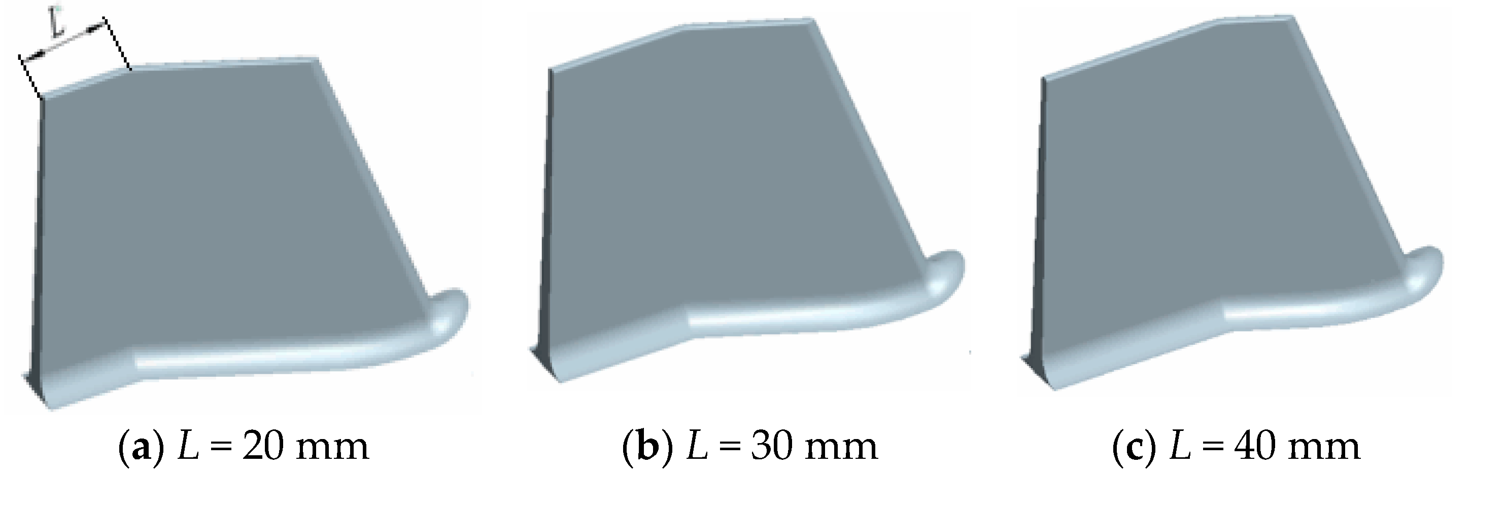
2.1. Model of the Fluid Domain

A vortex pump vane has a straight vane, bent vane, and a slanting vane of three kinds. The slanting vane can limit the fluid from a radial to an axial circulation flow and reduce the circulation loss, and the efficiency and head of the vortex pump improve to a certain degree; therefore, the slanting vane is the most widely used vane form [21,22,23,24]. This paper took the IS 125-80-230 (LXH) vortex pump as the object of study, with the specific parameters shown in Table 1. The vortex pump is a kind of R30-F30 vane vortex pump; R30 refers to the same direction of the rotation with an impeller slope angle of 30°, and F30 refers to the opposite direction of the rotation with an impeller slope angle of 30°. The second inclined section length (L) of the blade indicates the position of the bending point of the inclined blade to the distance at the impeller outlet. The R30-F30 blade was modeled in the research process for the three cases of L = 20, 30, and 40 mm, and the vortex pump blade structure is shown in Figure 1.
The fluid domain model of the vortex pump was constructed, including a suction chamber, pressure chamber, impeller fluid domain, and inlet and outlet fluid domain. Each part was assembled to establish a three-dimensional model of the vortex pump, as shown in Figure 2. This study used Pro/ENGINEER 3D modeling software to build a vortex pump fluid domain model, including a suction chamber, pressure chamber, impeller fluid domain, and the inlet and outlet pipe fluid domain parts, and to assemble each part to establish the vortex pump 3D calculation area model, as shown in Figure 2.

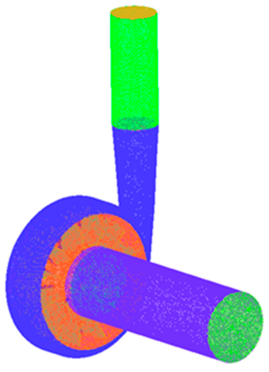
2.2. Mesh Partitioning

Before the numerical simulation calculation of the cyclonic pump, the fluid domain of the cyclonic pump must mesh. In this study, ICEM was chosen as the software for meshing, which is able to interface with Pro/ENGINEER and also to automatically span geometric defects and some redundant minute features. For the relatively complex pump body and impeller in the vortex pump, a tetrahedral mesh is a feasible choice for delineation. For the inlet and outlet pipes, the structure was simple; thus, it can be divided by hexahedral meshing. The overall meshing of the vortex pump is shown in Figure 3.
The form and number of meshes have a relatively large impact on the results of numerical simulations. To balance the accuracy of the numerical simulation and the speed and efficiency of the calculation, the grid needs to be irrelevant [25]. As shown in Figure 4, the head, shaft power, and efficiency of the vortex pump are stable when the number of grids for a model pump is greater than 1.4 million, and its error does not exceed 0.5%. Since a grid number of 1.8 million is low and most computers are now able to calculate quickly and efficiently, the total number of computational grids for the model pump was 18,066,545.

2.3. Cavitation Model and Parameter Setting

The RNG k-ε model establishes the mixing function and provides an analytical formula for the viscosity of low Reynolds number flow, which makes the turbulence model transition smoothly from the near-wall to the far-wall region with good accuracy and simulation effect; therefore, the RNG k-ε turbulence model was used for the numerical calculation of the flow field. The Zwart cavitation model, based on the Rayleigh–Plesset equation, which is characterized by correlating the density variation of the tiny bubbles in the flow field with their motion characteristics and assuming that all of the bubbles are the same size, was used, considering that the interphase mass transport rate is determined by the bubble number density [26,27,28], using the following equation.
When P < Pv, that is, when the flow field pressure is smaller than the liquid vaporization pressure at the temperature, and the liquid phase transforms to the gas phase, it is calculated using Formula (1):
R e = F vap 3 α ruc ( 1 α v ) ρ v R B 2 ( P v P ) 3 ρ 1
When P > Pv, the gas phase transforms to a liquid phase, it is calculated by Formula (2):
R c = F cond 3 α v ρ v R B 2 ( P P v ) 3 ρ 1
where P is the fluid field pressure; Pv is the vaporization pressure; Re is the steam generation rate; Rc is the steam condensation rate; Fvap and Fcond are the experience correction coefficient for the evaporation and the condensation progress; αruc is the volume fraction of the nucleation sites; αv is the bubble volume fraction; RB is the bubble radius; and ρv and ρ1, respectively, is the vapor density and liquid density.
The fluid in the vortex pump was 25 °C and composed of water and vapor. At this temperature, the vaporization pressure of the water was Pv = 3610 Pa, αruc = 5 × 10⁻⁴, and the average diameter of the bubble was set to RB = 1 × 10⁻⁶ m, Fvap = 50, and Fcond = 0.01. The reference pressure was set to 0 Pa; the boundary conditions were set to inlet total pressures of Pin = 3, 6, and 9 × 10⁴ Pa. These three inlet total pressures corresponded to the different degrees of cavitation: Pin = 3 × 10⁴ Pa, which corresponded to the strong cavitation phenomenon; Pin = 6 × 10⁴ Pa, which corresponded to the lighter cavitation phenomenon; and Pin = 9 × 10⁴ Pa, which corresponded to the slight cavitation phenomenon, which would not affect the operation. The outlet was the mass flow, and the first-order upwind scheme was used to calculate the fluid field. The accuracy was 10−4.

3. Cavitation Flow Analysis of the Vortex Pumps

3.1. Analysis of the Static Pressure Distribution of the Vortex Pump under Different Inlet Total Pressures

The pump’s internal (P) distribution of the different L values under the three cases of inlet total pressure are shown in Figure 5. The three cases of inlet total pressure were Pin = 3, 6, and 9 × 10⁴ Pa, shown from left to right. As shown in Figure 5, the static pressure from the impeller inlet to the outlet of the vortex pump increased gradually, and the inlet of the impeller was the lowest pressure region. The low-pressure region of the impeller was not evenly distributed, and the area in the 3 o’clock direction of the vortex pump impeller, due to the tongue, was a relatively low-pressure region in the whole flow passage. When the fluid flowed through the tongue, it caused a certain pressure pulsation; thus, the low-pressure regions were likely to have cavitation. With the increase in the total inlet pressure, the static pressure at the same position of the impeller of the vortex pump increased gradually, and the strength of the cavitation could be suppressed. When the total inlet pressure was large enough, the cavitation could be avoided. Comparing the three kinds of blades (i.e., L = 20, 30, and 40 mm), when L = 40 mm, the low-pressure region was larger than for L = 20 and 30 mm, and the low-pressure region spread to the second inclined part of the blade. If the fluid in the low-pressure region vaporized and flowed forward, it would sharply reduce and rupture when achieving the high-pressure region, causing a water hammer impact on the wall. Therefore, the probability of the occurrence of cavitation with the L = 40 mm blade was greater than for the other two cases. When L = 20 mm, the low-pressure region of the whole flow passage was significantly smaller; thus, it can be seen that a shorter L value can improve the impeller distribution of the impeller flow passage and reduce the low-pressure region inside the pump impeller. The reason for this is that when the L was shorter, the first inclined part length of the blade increased, and its ability to work on fluid became stronger and enhanced the anti-cavitation ability of the vortex pump.

3.2. Analysis of the Bubble Volume Fraction Distribution of the Vortex Pump Impeller under Different Inlet Total Pressures

The pump’s internal flow field (αv) distribution with different L values under the three cases of inlet total pressure is shown in Figure 6, and the three cases of inlet total pressure were Pin = 3, 6, and 9 × 10⁴ Pa, from left to right. As shown in Figure 6, the three kinds of vortex pump blades had different degrees of cavitation; the region of cavitation corresponded to the low-pressure region, and the region with the most serious cavitation was the area with the lowest pressure regions, which were the impeller inlet area and tongue area. The larger the radius of the impeller, the greater the pressure, and the degree of cavitation will be alleviated. With the increase in the inlet total pressure, the bubble inside the impeller of the vortex pump gradually reduced, and the cavitation phenomenon also gradually weakened, because the higher inlet total pressure could reduce the vaporization of the fluid and inhibit the occurrence of cavitation. Comparing the three blades with L = 20, 30, and 40 mm, it can be found that the vapor content increased with the increase in the L value. With L = 40 mm, the degree of cavitation was stronger than that for L = 20 and 30 mm, because the low-pressure area of the L = 40 mm blade was larger, which led to the increased generation of vapor bubbles. The generated bubbles flowed forward with the fluid, and when they reached the high-pressure area, the bubbles were squeezed by the surrounding high-pressure liquid so that they ruptured rapidly, which was also the reason for the smaller volume fraction of the bubbles with the larger impeller radius. However, at the same time, the bubble burst, and the fluid particle hypervelocity impacted the flow components, damaging the body of the pump and generating a large amount of noise and vibration. Thus, compared with the other two cases, the L = 40 mm blade showed a poor cavitation performance. When L = 20 mm, even if the low-pressure region of the impeller was much smaller, the too low inlet total pressure still caused severe cavitation, which was due to the impeller inlet pressure being lower than the fluid vaporization pressure, and the cavitation phenomenon could not be avoided. However, with the increase in the inlet total pressure, due to the better pressure distribution of the L= 20 mm blade, it showed a better anti-cavitation ability; therefore, when the inlet total pressure was not too low, the shorter L could reduce the vapor content inside the pump impeller, improving the anti-cavitation ability of the vortex pump.

3.3. Analysis of the Flow Streamline and Bubble Distribution of the Vortex Pump Impeller under Different Instants

When the inlet total pressure was Pin = 3 × 10⁴ Pa, the streamline and bubble distribution of the vortex pump with the different L values are shown in Figure 7. Due to the cavitation phenomenon of the vortex pump changing periodically, the impeller was divided per rotation into three time points for analysis; an internal flow field chart of the vortex pump every 120° was analyzed, as shown in Figure 7, from left to right, with the 0/3, 1/3, and 2/3 cycles. The impeller bubble volume fraction of the isosurface, as shown in Figure 7, was 0.3, and the streamlines were located in the middle section of the impeller.
The rotation direction of the impeller was counterclockwise, rotating from the 12 o’clock position of the 0/3 cycle. After a 120° rotation to the 1/3 cycle, it could be found that the bubble of the impeller had a tendency to become smaller, and the bubbles began to fall off. In addition, a large number of vortices were generated in this region, as shown in the streamlines. At the 12 o’clock position, the bubble produced by cavitation was minimal and the thinnest, consistent with the distribution of the static pressure in Figure 5. After turning 120° to the 2/3 cycle, the cavitation phenomenon at the impeller inlet began to deteriorate, the vapor bubble gradually started to become larger, the vapor bubble at the trailing edge of the impeller inlet started to become thicker and coarser, and the scope of the vapor bubble’s influence started to become larger. In addition, the vapor bubble in the inlet was in a state of local shedding, where it shed the vapor bubble after leaving the impeller trailing edge due to the rapid increase in pressure, and it rapidly transformed from a gaseous state to a liquid state. During this process, the liquid will continuously strike the surface of the pump’s body, causing cavitation damage. In summary, from the 1/3 cycle to the 2/3 cycle of the impeller’s rotation, the cavitation phenomenon gradually weakened but produced a large number of vortices. From the 2/3 cycle to cycle’s completion, the cavitation phenomenon rapidly aggravated; a large number of bubbles were produced and flowed forward with the fluid, and the water hammer generated by the subsequent rupture was the main reason for the vortex pump cavitation phenomenon. The vortex generated in the operation of the vortex pump caused cavitation in the low-pressure region of the vortex, leading to severe vortex cavitation, which was the cause of the severe cavitation in the vortex pump.
Comparing the three blades (i.e., L = 20, 30, and 40 mm), with the increase in the L value, the bubble volume fraction increased, and the cavitation became more serious. The analysis of the streamlines also showed that with the increase in the L value, the fluid velocity gradient became larger, and the change in the flow rate intensified, leading to a reduction of the local pressure inside the pump, forming a large number of vapor bubbles. In addition, the increase in the L value caused the deliquescence to be more serious, which also increased the intensity of cavitation.

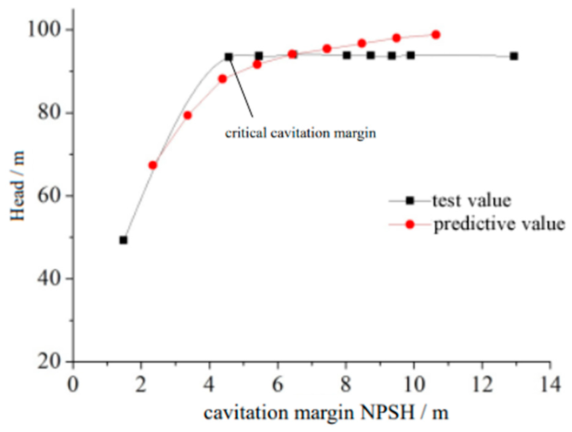
4. Test Verification

A vortex pump cavitation test system was used to test the cavitation characteristics of the vortex pump. Using an open test bench, the design of the test bench was in line with national standards (GB/T3126), with a B-level accuracy. The test site diagram is shown in Figure 8. An orifice flow meter was used for the pump flow measurements, a torque sensor was used to measure the shaft power of the pump, and a standard pressure gauge was used to measure the pressure at the inlet and outlet of the vortex pump. The fluid pressure distribution at the inlet and outlet of the vortex pump was measured with an electromagnetic manometer during the experiment, and the sensor was located at the inlet and outlet positions of the vortex pump. During the test, the pressure, flow, torque, and speed of the inlet and outlet of the vortex pump were measured, where the integrated error of the test system was 0.86%, and the cavitation condition of the test pump was produced by changing the pressure at the impeller inlet. The predicted value for the L = 30 mm vortex pump was taken in comparison with the test value to verify the credibility of the simulation results.
The vortex pump test flow–head curves and flow effectiveness curves are shown in Figure 9. As can be observed, the tendency of the numerical simulation results basically agreed with the experimental results. The numerical simulation value of the head was slightly higher than the test value, while the value of the efficiency was lower than the test value. Under different conditions, there was a difference of approximately 5% between the numerical simulation value for the head and the test value; although the efficiency had a larger fluctuation, in the case of a small flow, the gap between the test value and the simulation value was larger, and the difference was 5%. With the increase in the flow rate, the efficiency value of the test value was close to the simulation value, which was similar than the prediction trend.
The relationship between the cavitation margin and the head of the vortex pump is shown in Figure 10. It can be observed that the change tendency of the predicted value and the test value basically coincided. The difference between them was that the predictive head decreased slowly with the decrease in the cavitation margin, but the test value was basically unchanged before the critical cavitation margin, and it was very stable. The common feature was that when reaching the critical cavitation margin, the head of both the test value and predictive value declined sharply. Overall, the results of the numerical simulation accurately reflected the cavitation performance of the vortex pumps and had a certain reliability.

5. Conclusions

(1)
For the vortex pump with the same inlet total pressure, the longer the second inclined part length of the inclined blade, the larger the low-pressure region inside the flow passage, and this led to more fluid vaporization. When the vaporization bubble reached the high-pressure region, the volume decreased sharply and resulted in a burst, causing severe cavitation; therefore, a shorter second inclined part length could improve the pressure distribution inside the vortex pump flow passage to reduce the possibility of cavitation.
(2)
With the increase in the length of the second inclined part of the inclined blade, the bubble volume fraction in the flow passage of the vortex pump increased under the same inlet total pressure inside. The shorter the second inclined part length, the smaller the bubble volume fraction in the flow passage, resulting in a better cavitation performance of the vortex pump. When the inlet total pressure was too low, the change in the length of the second inclined part could not restrain the occurrence of cavitation, leading to severe cavitation.
(3)
When the impeller inlet total pressure was low, resulting in a large number of vortices in the flow passage, the hole generated in the low-pressure region of the vortex led to severe impact and vortex cavitation, which was the reason for the serious cavitation of the vortex pump. With the increase in the length of the second inclined part of the inclined blade, the increase in the rate of change of the fluid velocity and the worse flow separation led to more intense cavitation.
(4)
The results of the test and numerical calculation were consistent; before the critical cavitation margin, with the decrease in the cavitation margin, the pump head slowly decreased, while after reaching the critical cavitation margin, the head declined sharply.

Author Contributions

Conceptualization, Z.Y. and Y.G.; methodology, Z.Y. and T.F.; software, Z.Y.; validation, Z.L., W.W., and T.F.; formal analysis, Y.G.; investigation, Z.Y.; resources, Y.G.; data curation, Y.G.; writing—original draft preparation, Z.Y.; writing—review and editing, J.M.; visualization, Z.Y.; supervision, Z.L. and D.W.; project administration, S.Z.; funding acquisition, Y.G. All authors have read and agreed to the published version of the manuscript.

Funding

This work was supported by the Zhejiang Provincial Natural Science Foundation of China (LY22E050015), the Science and Technology Plan Project of State Administration for Market Regulation (2020MK192), the Zhejiang Provincial Science and Technology Plan Project of China (2021C01052), the National Natural Science Foundation of China (51976193), and the Zhejiang Provincial National Science Foundation of China (LGG22E060011).

Institutional Review Board Statement

Not applicable.

Informed Consent Statement

Not applicable.

Data Availability Statement

Not applicable.

Conflicts of Interest

The authors declare no conflict of interest.

References

  1. Quan, H.; Li, Y.; Kang, L.; Yu, X.; Song, K.; Wu, Y. Influence of Blade Type on the Flow Structure of a Vortex Pump for Solid-Liquid Two-Phase Flow. Machines 2021, 9, 353. [Google Scholar] [CrossRef]
  2. Peng, G.; Chen, Q.; Zhou, L.; Pan, B.; Zhu, Y. Effect of blade outlet angle on the flow field and preventing overload in a centrifugal pump. Micromachines 2020, 11, 811. [Google Scholar] [CrossRef] [PubMed]
  3. Xu, Y.; Tan, L.; Liu, Y.; Cao, S. Pressure fluctuation and flow pattern of a mixed-flow pump with different blade tip clearances under cavitation condition. Adv. Mech. Eng. 2017, 9, 1687814017696227. [Google Scholar] [CrossRef] [Green Version]
  4. Li, W. Vortex Pump as Turbine for Energy Recovery in Viscous Fluid Flows With Reynolds Number Effect. J. Fluids Eng. 2022, 144, 021207. [Google Scholar] [CrossRef]
  5. He, C.; Gu, Y.; Zhang, J.; Ma, L.; Yan, M.; Mou, J.; Ren, Y. Preparation and modification technology analysis of ionic polymer-metal composites (IPMCs). Int. J. Mol. Sci. 2022, 23, 3522. [Google Scholar] [CrossRef] [PubMed]
  6. Gu, Y.; Yu, L.; Mou, J.; Wu, D.; Xu, M.; Zhou, P.; Ren, Y. Research strategies to develop environmentally friendly marine antifouling coatings. Mar. Drugs 2020, 18, 371. [Google Scholar] [CrossRef]
  7. Svoboda, D.G.; Zharkovskii, A.A.; Ivanov, E.A. Influence of the Geometric Parameters of the Impeller of a Free-Vortex Pump on the Energy and Cavitation Characteristics of the Pump. Chem. Pet. Eng. 2019, 54, 673–680. [Google Scholar] [CrossRef]
  8. Gao, X.; Zhao, T.; Shi, W.; Zhang, D.; Shi, Y.; Zhou, L.; Chang, H. Numerical investigation of an open-design vortex pump with different blade wrap angles of impeller. Processes 2020, 8, 1601. [Google Scholar] [CrossRef]
  9. Huan, Y.; Liu, Y.; Li, X.; Zhu, Z.-C.; Qu, J.-T.; Zhe, L.; Han, A.-D. Experimental and numerical investigations of cavitation evolution in a high-speed centrifugal pump with inducer. J. Hydrodyn. 2021, 33, 140–149. [Google Scholar] [CrossRef]
  10. Kondić, Ž.; Medić, S.; Kondić, V. Experimental and Numerical Investigation of Centrifugal Vortex Pump Operating Benefits for Energy Efficient Systems. Teh. Vjesn. 2020, 27, 1519–1523. [Google Scholar]
  11. Cheng, X.; Chang, Z.; Jiang, Y. Study on the influence of the specific area of balance hole on cavitation performance of high-speed centrifugal pump. J. Mech. Sci. Technol. 2020, 34, 3325–3334. [Google Scholar] [CrossRef]
  12. Ye, D.; Li, H.; Ma, Q.; Han, Q.; Sun, X. Numerical Investigation of Performance Improvement and Erosion Characteristics of Vortex Pump Using Particle Model. Shock. Vib. 2020, 2020, 5103261. [Google Scholar] [CrossRef]
  13. Ju, Y.; Liu, S.; Zhang, C. Effect of blade shape on hydraulic performance and vortex structure of vortex pumps. J. Hydrodyn. 2018, 30, 499–506. [Google Scholar] [CrossRef]
  14. Quan, H.; Guo, Y.; Li, R.; Su, Q.; Chai, Y. Optimization design and experimental study of vortex pump based on orthogonal test. Sci. Prog. 2020, 103, 0036850419881883. [Google Scholar] [CrossRef] [Green Version]
  15. Gu, Y.; Zhang, J.; Yu, S.; Mou, C.; Li, Z.; He, C.; Wu, D.; Mou, J.; Ren, Y. Unsteady numerical simulation method of hydrofoil surface cavitation. Int. J. Mech. Sci. 2022, 228, 107490. [Google Scholar] [CrossRef]
  16. Guo, C.; Gao, M.; Wang, J.; Shi, Y.; He, S. The effect of blade outlet angle on the acoustic field distribution characteristics of a centrifugal pump based on Powell vortex sound theory. Appl. Acoust. 2019, 155, 297–308. [Google Scholar] [CrossRef]
  17. Yan, D.; Kovacevic, A.; Tang, Q.; Rane, S. Numerical investigation of cavitation in twin-screw pumps. Proc. Inst. Mech. Eng. Part C J. Mech. Eng. Sci. 2018, 232, 3733–3750. [Google Scholar] [CrossRef] [Green Version]
  18. Han, C.; Xu, S.; Cheng, H.; Ji, B.; Zhang, Z.-Y. LES method of the tip clearance vortex cavitation in a propelling pump with special emphasis on the cavitation-vortex interaction. J. Hydrodyn. 2020, 32, 1212–1216. [Google Scholar] [CrossRef]
  19. Li, J.; Tang, L.; Zhang, Y. The influence of blade angle on the performance of plastic centrifugal pump. Adv. Mater. Sci. Eng. 2020, 2020, 7205717. [Google Scholar] [CrossRef]
  20. Cheng, H.; Ji, B.; Long, X.; Huai, W.-X.; Farhat, M. A review of cavitation in tip-leakage flow and its control. J. Hydrodyn. 2021, 33, 226–242. [Google Scholar] [CrossRef]
  21. Quan, H.; Wu, Y.; Guo, Y.; Mastroroberto, P.; Speziale, G.; Nasso, G. Multiobjective Hydraulic Design and Performance Analysis of a Vortex Pump Based on Orthogonal Tests. Shock Vib. 2021, 2021, 6687856. [Google Scholar] [CrossRef]
  22. Condello, I.; Santarpino, G.; Serraino, G.F.; Mastroroberto, P.; Speziale, G.; Nasso, G. Magnetic levitation pump versus constrained vortex pump: A pilot study on the hemolysis effect during minimal invasive extracorporeal circulation. J. Cardiothorac. Surg. 2021, 16, 1–4. [Google Scholar] [CrossRef] [PubMed]
  23. Rosanov, N.N.; Fedorov, S.V. Topology of energy fluxes in vortex dissipative soliton structures. J. Opt. 2016, 18, 074005. [Google Scholar] [CrossRef]
  24. Sookhak, M.; Gani, A.; Talebian, H.; Akhunzada, A.; Khan, S.U.; Buyya, R.; Zomaya, A.Y. Remote Data Auditing in Cloud Computing Environments: A Survey, Taxonomy, and Open Issues. Acm Comput. Surv. 2015, 47, 65. [Google Scholar] [CrossRef]
  25. Dratman, E.; Matera, G. Newton’s method and a mesh-independence principle for certain semilinear boundary-value problems. J. Comput. Appl. Math. 2016, 292, 188–212. [Google Scholar] [CrossRef]
  26. Zhao, Y.; Wang, G.; Huang, B. A cavitation model for computations of unsteady cavitating flows. Acta Mech. Sin. 2016, 32, 273–283. [Google Scholar] [CrossRef]
  27. Chen, G.H.; Wang, G.Y.; Huang, B.; Hu, C.L.; Wang, Z.Y.; Wang, J. Numerical investigation of dynamics of unsteady sheet/cloud cavitating flow using a compressible fluid model. Mod. Phys. Lett. B 2015, 29, 1450269. [Google Scholar] [CrossRef]
  28. Ye, Y.; Li, G. Modeling of hydrodynamic cavitating flows considering the bubble-bubble interaction. Int. J. Multiph. Flow 2016, 84, 155–164. [Google Scholar] [CrossRef]
Figure 1. Models of the different L values of the blades.
Machines 11 00021 g001
Figure 2. Calculation model of the vortex pump.
Machines 11 00021 g002
Figure 3. Vortex pump meshing.
Machines 11 00021 g003
Figure 4. Effect of the grid number on the numerical simulation results.
Machines 11 00021 g004
Figure 5. Internal (P) distribution of the pump with different L values under the three cases of inlet total pressure.
Machines 11 00021 g005
Figure 6. The internal flow field (αv) distribution of the pump with different L values under the three cases of inlet total pressure.
Machines 11 00021 g006
Figure 7. Flow streamline and bubble distribution of the vortex pump impeller under different instants and L values.
Machines 11 00021 g007
Figure 8. Test site map.
Machines 11 00021 g008
Figure 9. Comparison of the performance parameters of the vortex pump.
Machines 11 00021 g009
Figure 10. Cavitation margin and head curve of the vortex pump.
Machines 11 00021 g010
Table 1. The vortex pump parameters.
Inlet DiameterOutlet DiameterImpeller DiameterFlow (Q)Head (H)Cavitation Margin (NPSH)Power (P)
125 mm80 mm230 mm144 m3/s80 m3.6 m75 kW
Disclaimer/Publisher’s Note: The statements, opinions and data contained in all publications are solely those of the individual author(s) and contributor(s) and not of MDPI and/or the editor(s). MDPI and/or the editor(s) disclaim responsibility for any injury to people or property resulting from any ideas, methods, instructions or products referred to in the content.

