


Performance Enhancement of Direct Torque and Rotor Flux Control (DTRFC) of a Three-Phase Induction Motor over the Entire Speed Range: Experimental Validation †


Abstract
:1. Introduction
2. Theories and Principles
3. The Effect of VVs at Low Speeds in the DTRFC Algorithm
4. The Effect of VVs at High Speeds in DTRFC Algorithm
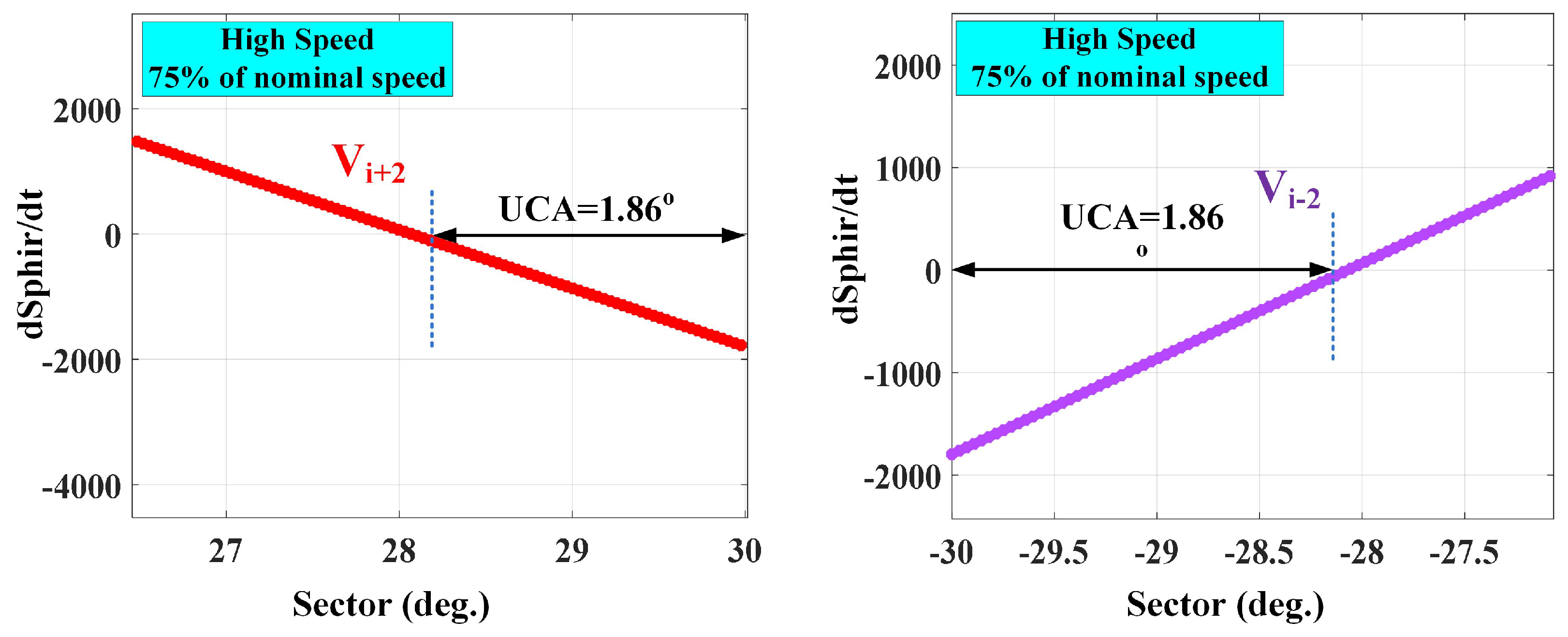
5. Determination of UCAs Values at Low and High Speeds
6. The Proposed 18 SSs DTRFC Strategy for Medium High Speeds
- For the first sub-sector, shown in Figure 7a, it can easily be seen that the four effective vectors achieve the optimum condition for the two controlled functions and because their sign does not reverse over the entire .
- For the second sub-sector, shown in Figure 7b, the choice of the two vector achieve the optimum condition of the control requirements for the two controlled functions and in the first and second quadrants, respectively. However, there is only one choice in the third and fourth quadrants, which is the vector . The latter vector fulfils the optimum control requirements for the torque without achieving that for the rotor flux as it causes UCA.
- For the third sub-sector, shown in Figure 7c, it can easily be seen that the four effective VVs achieve the optimum condition for the two controlled functions and as long as they maintain their sign over the entire .
- 1.
- 2.
- 3.
7. Determination of the Transition Speed between the Conventional and Improved Strategy
8. Comparison of Current Case Studies toward the Proposed 18-SS DTRFC
9. Simulation Results
10. Hardware Experimental Results
11. Conclusions
- The use of a normal 6-sector DTRFC technique allows for simplicity at low speeds.
- High performance at medium and high speeds is due to the elimination of the uncontrollable angles of the torque response.
- Accurate analytical determination of the transition speed between traditional and improved strategy.
- The switching table is based on the analysis’s findings, not on designer experience.
- There is no increase in the switching frequency due to the increased number of sectors.
- Robustness to the parameters variations.
- Lower chattering of the torque at high speed when compared with classical strategy.
Author Contributions
Funding
Institutional Review Board Statement
Informed Consent Statement
Data Availability Statement
Conflicts of Interest
Appendix A

| Abbreviation | Definition |
|---|---|
| PWM | Pulse Width Modulation |
| FOC | Field-Oriented Control |
| DTC | Direct Torque Control |
| DTRFC | Direct Torque and Rotor Flux Control |
| UCAs | Uncontrollable angles |
| IM | Induction Motor |
| PMSM | Permanent Magnet Synchronous Motor |
| CSFC | Constant Switching Frequency Controller |
| VVs | Voltage Vectors |
| VSI | Voltage Source Inverter |
| HCs | Hysteresis Controllers |
| LUT | Lookup Table |
| SS | Sub-Sector |
Appendix B
| Variable | Unit Value |
|---|---|
| Nominal voltage | 230/400 V |
| Phase resistance stator | |
| Phase resistance rotor | |
| Phase inductance stator | |
| Phase inductance rotor | |
| Mutual inductance | |
| Inertia | = 0.006 kg·m |
| Friction factor | = 0.001 N·m.s/rad |
| Number of poles pairs | = 2 |
| Nominal stator flux | = 1.14 Wb |
| Nominal rotor flux | = 0.945 Wb |
| Nominal power | = 0.25 kW |
| Nominal frequency | = 50 Hz |
| Nominal speed | = 282 rad/s |
| Nominal torque | = 1.76 N |
References
- Takahashi, M.; Noguchi, T. A New Quick-Response and High-Effecincy Control Strategy of an Induction Motor. IEEE Trans. Ind. Appl. 1986, IA-22, 820–827. [Google Scholar] [CrossRef]
- Buja, G.; Kazmierkowski, M. Direct Torque Control of PWM Inverter Fed AC Motors—A Survey. IEEE Trans. Ind. Electron. 2004, 51, 744–757. [Google Scholar] [CrossRef]
- Lascu, C.; Boldea, I.; Blaabjerg, F. Variable-Structure Direct Torque Control—A Class of Fast and Robust Controllers for Induction Machine Drives. IEEE Trans. Ind. Electron. 2004, 51, 785–792. [Google Scholar] [CrossRef]
- Idris, N.; Yatim, A. Direct Torque Control of Induction Machines With Constant Switching Frequency and Reduced Torque Ripple. IEEE Trans. Ind. Electron. 2004, 51, 758–767. [Google Scholar] [CrossRef]
- Toh, C.; Idris, N.; Yatim, A. Constant and High Switching Frequency Torque Controller for DTC Drives. IEEE Power Electron. Lett. 2005, 31, 76–80. [Google Scholar] [CrossRef] [Green Version]
- Naassani, A.; Monmasson, E.; Louis, J. Synthesis of Direct Torque and Rotor Flux Control Algorithms by Means of Sliding-Mode Theory. IEEE Trans. Ind. Electron. 2005, 52, 785–799. [Google Scholar] [CrossRef]
- Abad, G.; Rodriguez, A.; Poza, J. Two-level VSC Based Predictive Direct Torque Control of The Double Fed Induction Machine With Reduced Torque and Flux Ripples at Low Constant Switching Frequency. IEEE Trans. Power Electron. 2005, 23, 1050–1061. [Google Scholar] [CrossRef]
- Ryu, J.; Lee, K.; Lee, J. A Unified Flux and Torque Control Method for DTC- Based Induction-Motor Drives. IEEE Trans. Power Electron. 2006, 21, 234–242. [Google Scholar] [CrossRef]
- Nikzad, M.; Asaei, B.; Ahmadi, S. Discrete Duty-Cycle-Control Method for Direct Torque Control of Induction Motor Drives With Model Predictive Solution. IEEE Trans. Power Electron. 2018, 33, 2317–2329. [Google Scholar] [CrossRef]
- Meesala, R.; Thippiripati, V. An Improved Direct Torque Control of Three-Level Dual Inverter Fed Open-Ended Winding Induction Motor Drive Based on Modified Look-Up Table. IEEE Trans. Power Electron. 2020, 35, 3906–3917. [Google Scholar] [CrossRef]
- Alsofyani, I.; Bak, Y.; Lee, K. Fast Torque Control and Minimized Sector-Flux Droop for Constant Frequency Torque Controller Based DTC of Induction Machines. IEEE Trans. Power Electron. 2019, 34, 12141–12153. [Google Scholar] [CrossRef]
- Yang, G.; Yang, J.; Li, S.; Wang, Y.; Hussain, H.; Deng, R.; Yan, L. A Sequential Direct Torque Control Scheme for Seven-Phase Induction Machines Based on Virtual Voltage Vectors. IEEE Trans. Ind. Appl. 2021, 57, 3722–3734. [Google Scholar] [CrossRef]
- Alsofyani, I.; Lee, K. Enhanced Performance of Constant Frequency Torque Controller–Based Direct Torque Control of Induction Machines with Increased Torque-Loop Bandwidth. IEEE Trans. Ind. Electron. 2020, 67, 10168–10179. [Google Scholar] [CrossRef]
- Cirrincione, M.; Pucci, M.; Vitale, G. A New Direct Torque Control Strategy for the Minimization of Common-Mode Emissions. IEEE Trans. Ind. Appl. 2006, 24, 504–517. [Google Scholar] [CrossRef]
- Deng, W.; Li, H.; Rong, J. A Novel Direct Torque Control of Matrix Converter-Fed PMSM Drives Using Dynamic Sector Boundary for Common-Mode Voltage Minimization. IEEE Trans. Ind. Electron. 2021, 68, 70–80. [Google Scholar] [CrossRef]
- Lascu, C.; Jafarzadeh, S.; Fadali, S. Direct Torque Control With Feedback Linearization for Induction Motor Drives. IEEE Trans. Power Electron. 2017, 32, 2072–2080. [Google Scholar] [CrossRef]
- Naik, N.; Singh, S. A Comparative Analytical Performance of F2DTC and PIDTC of Induction Motor Using DSPACE-1104. IEEE Trans. Ind. Electron. 2015, 62, 7350–7359. [Google Scholar] [CrossRef]
- Alsofyani, I.; Idris, N. Simple flux regulation for improving state estimation at very low and zero speed of a speed sensorless direct torque control of an induction motor. IEEE Trans. Power Electron. 2015, 2, 3027–3035. [Google Scholar] [CrossRef]
- Alsofyani, I.; Idris, N.; Lee, K. Dynamic Hysteresis Torque Band for Improving the Performance of Lookup-Table-Based DTC of Induction Machines. IEEE Trans. Power Electron. 2018, 33, 7959–7970. [Google Scholar] [CrossRef]
- Wang, X.; Wang, Z.; Xu, Z.; Hu, Y. Optimization of Torque Tracking Performance for Direct-Torque-Controlled PMSM Drives With Composite Torque Regulator. IEEE Trans. Ind. Electron. 2020, 67, 10095–10108. [Google Scholar] [CrossRef]
- Wang, M.; Sun, D.; Ke, W.; Nian, H. A Universal Lookup Table-Based Direct Torque Control for OW-PMSM Drives. IEEE Trans. Power Electron. 2021, 36, 6188–6191. [Google Scholar] [CrossRef]
- Wu, X.; Huang, W.; Lin, X.; Jiang, W.; Zhao, Y.; Zhu, S. Direct Torque Control for Induction Motors Based on Minimum Voltage Vector Error. IEEE Trans. Ind. Electron. 2021, 68, 3794–3804. [Google Scholar] [CrossRef]
- Nasr, A.; Gu, C.; Wang, X.; Buticchi, G.; Bozhko, S.; Gerada, C. Torque-Performance Improvement for Direct Torque-Controlled PMSM Drives Based on Duty-Ratio Regulation. IEEE Trans. Power Electron. 2022, 37, 749–760. [Google Scholar] [CrossRef]
- Elgbaily, M.; Anayi, F.; Packianather, M. Genetic and particle swarm optimization algorithms based direct torque control for torque ripple attenuation of induction motor. Mater. Today Proc. 2022, 67, 577–590. [Google Scholar] [CrossRef]
- Fahassa, C.; Zahraoui, Y.; Akherraz, M.; Kharrich, M.; Elattar, E. Induction Motor DTC Performance Improvement by Inserting Fuzzy Logic Controllers and Twelve-Sector Neural Network Switching Table. Mathematics 2022, 10, 1357. [Google Scholar] [CrossRef]
- Awwad, A.E. Dynamic Performance Enhancement of a Direct-Driven PMSG-Based Wind Turbine Using a 12-Sectors DTC. World Electr. Veh. J. 2022, 13, 123. [Google Scholar] [CrossRef]
- El Haissouf, M.; El Haroussi, M.; Ba-Razzouk, A. DSP In the Loop implementation of an enhanced Direct Torque Control for Induction Motor drive. In Proceedings of the 2022 IEEE 2nd International Conference on Innovative Research in Applied Science, Engineering and Technology (IRASET), Meknes, Morocco, 3–4 March 2022. [Google Scholar] [CrossRef]
- Elgbaily, M.; Anayi, F.; Packianather, M. Performance Improvement Based Torque Ripple Minimization for Direct Torque Control Drive Fed Induction Motor Using Fuzzy Logic Control. In Control, Instrumentation and Mechatronics: Theory and Practice; Springer Nature: Singapore, 2022; pp. 416–428. [Google Scholar] [CrossRef]
- Suresh, S.; Rajeevan, P.P. Virtual Space Vector Based Direct Torque Control Schemes for Induction Motor Drives. IEEE Trans. Ind. Appl. 2020, 56, 2719–2728. [Google Scholar] [CrossRef]
- Wu, Z.; Zhou, J.; Zheng, G.; Li, T.; Zhu, Z. New Eighteen-sector Direct Torque Control Based on Duty Ratio Modulation. In Proceedings of the 2019 Journal of Physics 2nd International Symposium on Power Electronics and Control Engineering (ISPECE 2019), Tianjin, China, 22–24 November 2019. [Google Scholar] [CrossRef]
- Bhangale, S.V.; Kumar, R.; Bhangale, K. 18-Sector Direct Torque Controlled Strategy with Improved Stator Flux Estimator for Induction Motor Drive. In Proceedings of the 2018 IEEE 8th IEEE India International Conference on Power Electronics (IICPE), Jaipur, India, 13–15 December 2018. [Google Scholar] [CrossRef]
- Jibril, M. 24 sectors DTC control with fuzzy hysteresis comparators for DFIM fed by three-level inverter. WSEAS Trans. Electron. 2021, 12, 141–154. [Google Scholar] [CrossRef]
- Kim, S.-K.; Kim, J.S.; Lee, Y.I. Model predictive control (MPC) based direct torque control (DTC) of permanent magnet synchronous motors (PMSMs). In Proceedings of the IEEE International Symposium on Industrial Electronics, Taipei, Taiwan, 28–31 May 2013. [Google Scholar] [CrossRef]
- Li, Y.-H.; Wu, T.-X.; Zhai, D.-W.; Zhao, C.-H.; Zhou, Y.-F.; Qin, Y.-G.; Su, J.-S.; Qin, H. Hybrid Decision Based on DNN and DTC for Model Predictive Torque Control of PMSM. Symmetry 2022, 14, 693. [Google Scholar] [CrossRef]
- Englert, T.; Grüner, S.; Graichen, K. Model predictive torque control of permanent magnet synchronous machines. IFAC-PapersOnLine 2017, 50, 758–763. [Google Scholar] [CrossRef]
- Aziz, A.G.M.A.; Rez, H.; Diab, A.A.Z. Robust Sensorless Model-Predictive Torque Flux Control for High-Performance Induction Motor Drives. Mathematics 2021, 9, 403. [Google Scholar] [CrossRef]
- Kakouche, K.; Rekioua, T.; Mezani, S.; Oubelaid, A.; Rekioua, D.; Blazek, V.; Prokop, L.; Misak, S.; Bajaj, M.; Ghoneim, S.S.M. Model Predictive Direct Torque Control and Fuzzy Logic Energy Management for Multi Power Source Electric Vehicles. Sensors 2022, 22, 5669. [Google Scholar] [CrossRef] [PubMed]
- Alshbib, M.M.; Elgbaily, M.M.; Anayi, F. An in-depth Analytical Study of the Switching States of Direct Torque Control Algorithm of an Induction Motor over the Entire Speed Range. Eng. Proc. 2022, 24, 27. [Google Scholar] [CrossRef]
- Buja, G.; Menis, R. Steady-State Performance Degradation of a DTC IM Drive Under Parameter and Transduction Errors. IEEE Trans. Ind. Electron. 2008, 55, 1749–1760. [Google Scholar] [CrossRef]
- O’Rourke, C.J.; Qasim, M.M.; Overlin, M.R.; Kirtley, J.L. A Geometric Interpretation of Reference Frames and Transformations: Dq0, Clarke and Park. IEEE Trans. Energy Convers. 2019, 34, 2070–2083. [Google Scholar] [CrossRef]
- Kabache, N.; Moulahoum, S.; Houassine, H. FPGA Implementation of direct Rotor Field Oriented Control for Induction Motor. In Proceedings of the 2013 IEEE 18th International Conference on Methods & Models in Automation & Robotics (MMAR), Miedzyzdroje, Poland, 26–29 August 2013. [Google Scholar] [CrossRef]
- Elgbaily, M.; Anayi, F.; Alshbib, M.M. A Combined Control Scheme of Direct Torque Control and Field-Oriented Control Algorithms for Three-Phase Induction Motor: Experimental Validation. Mathematics 2022, 10, 3842. [Google Scholar] [CrossRef]


| 6-Sector Index | |||||||
|---|---|---|---|---|---|---|---|
| 1 | 2 | 3 | 4 | 5 | 6 | ||
| 0 | 0 | ||||||
| 1 | |||||||
| 1 | 0 | ||||||
| 1 | |||||||
| Sub-Sectors Index | ||
|---|---|---|
| 0:15 | 15:45 | 45:60 |
| 300:315 | 315:345 | 345:360 |
| Sub-Sectors Index | |||||||||||||||||||
|---|---|---|---|---|---|---|---|---|---|---|---|---|---|---|---|---|---|---|---|
| 1 | 2 | 3 | 4 | 5 | 6 | 7 | 8 | 9 | 10 | 11 | 12 | 13 | 14 | 15 | 16 | 17 | 18 | ||
| 0 | 0 | ||||||||||||||||||
| 1 | |||||||||||||||||||
| 1 | 0 | ||||||||||||||||||
| 1 | |||||||||||||||||||
| Operating Parameters Values | Classical 6-Sector DTRFC | Improved 18-SS DTRFC |
|---|---|---|
| Torque ripples (low and medium speed) | 0.55 N.m | 0.55 N.m |
| Torque ripples (High speed) | 0.75 N.m | 0.55 N.m |
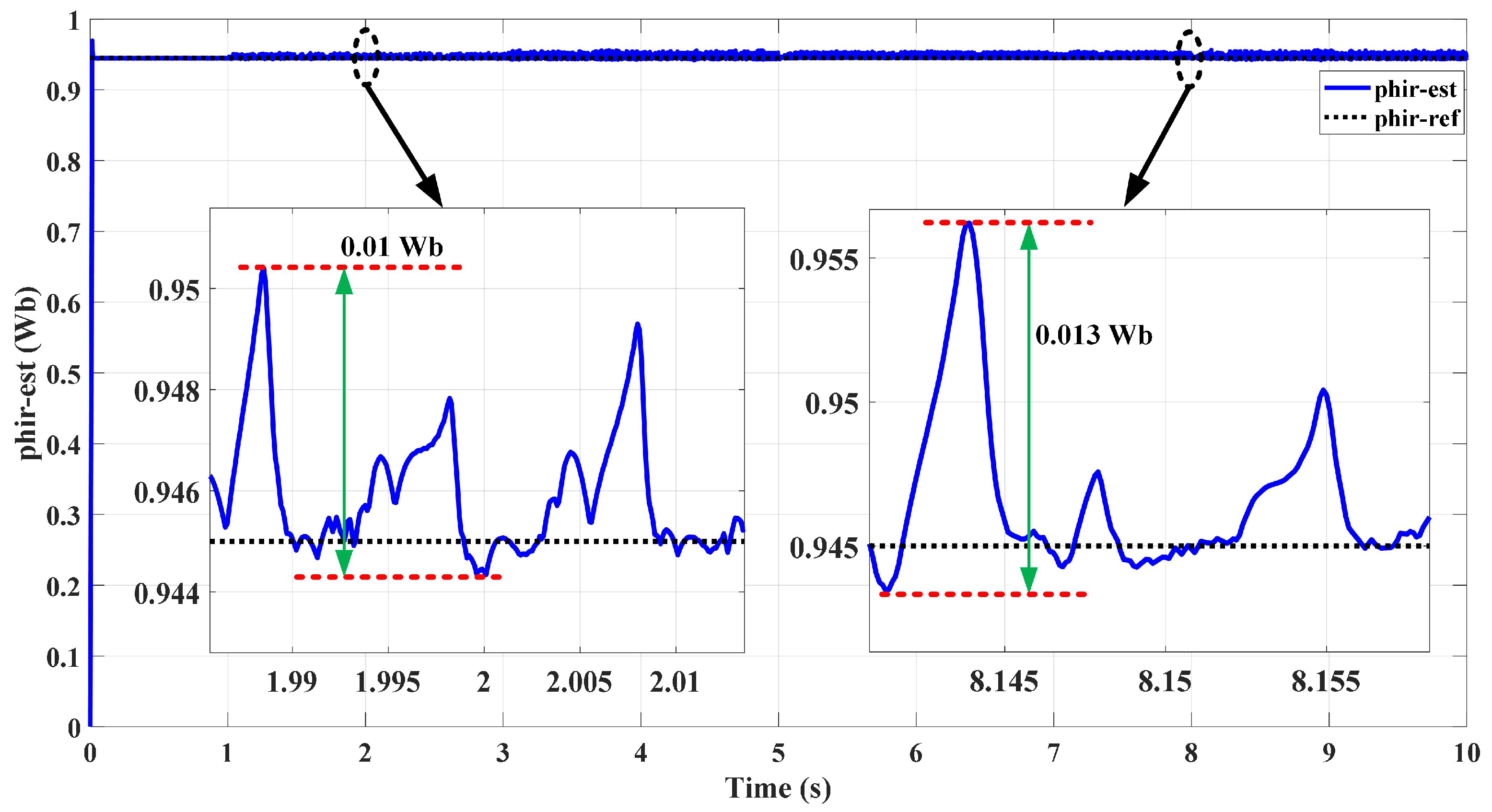
| Flux ripples | 0.01 Wb | 0.013 Wb |
| Switching frequency (low and medium speed) | 6 to 7.8 kHz | 6 to 7.8 kHz |
| Switching frequency (nominal speed) | 3 kHz | 2.5 kHz |
| Parameters variations | Weak | Strong |
| Lookup Table construction | Designer’s knowledge | Analytically |
| UCAs | Exist | Fully eliminated |
| Computational time | 18.5 s | 22.3 s |
| Speed Range (rad /s) | Classical DTC | Proposed DTC |
|---|---|---|
| 100 | 6100 Hz | 6000 Hz |
| 150 | 5350 Hz | 5100 Hz |
| 200 | 4215 Hz | 3900 Hz |
| 250 | 3250 Hz | 2850 Hz |
Disclaimer/Publisher’s Note: The statements, opinions and data contained in all publications are solely those of the individual author(s) and contributor(s) and not of MDPI and/or the editor(s). MDPI and/or the editor(s) disclaim responsibility for any injury to people or property resulting from any ideas, methods, instructions or products referred to in the content. |
© 2022 by the authors. Licensee MDPI, Basel, Switzerland. This article is an open access article distributed under the terms and conditions of the Creative Commons Attribution (CC BY) license (https://creativecommons.org/licenses/by/4.0/).
Share and Cite
Alshbib, M.M.; Elgbaily, M.M.; Alsofyani, I.M.; Anayi, F. Performance Enhancement of Direct Torque and Rotor Flux Control (DTRFC) of a Three-Phase Induction Motor over the Entire Speed Range: Experimental Validation. Machines 2023, 11, 22. https://doi.org/10.3390/machines11010022
Alshbib MM, Elgbaily MM, Alsofyani IM, Anayi F. Performance Enhancement of Direct Torque and Rotor Flux Control (DTRFC) of a Three-Phase Induction Motor over the Entire Speed Range: Experimental Validation. Machines. 2023; 11(1):22. https://doi.org/10.3390/machines11010022
Chicago/Turabian StyleAlshbib, Mussaab M., Mohamed Mussa Elgbaily, Ibrahim Mohd Alsofyani, and Fatih Anayi. 2023. "Performance Enhancement of Direct Torque and Rotor Flux Control (DTRFC) of a Three-Phase Induction Motor over the Entire Speed Range: Experimental Validation" Machines 11, no. 1: 22. https://doi.org/10.3390/machines11010022