Article

Film Cooling Performance of a Cylindrical Hole with an Upstream Crescent-Shaped Block in Linear Cascade

1
Tianjin Key Laboratory for Advanced Mechatronic System Design and Intelligent Control, School of Mechanical Engineering, Tianjin University of Technology, Tianjin 300384, China
2
National Demonstration Center for Experimental Mechanical and Electrical Engineering Education, Tianjin University of Technology, Tianjin 300384, China
3
School of Energy and Power Engineering, Shandong University, Jinan 250061, China
4
Deepinfar Ocean Technology Inc., Tianjin 300457, China
*
Author to whom correspondence should be addressed.
Machines 2023, 11(1), 110; https://doi.org/10.3390/machines11010110
Submission received: 7 December 2022 / Revised: 8 January 2023 / Accepted: 11 January 2023 / Published: 13 January 2023
(This article belongs to the Special Issue Heat Transfer and Energy Harvesting in Fluid System)

Abstract

:
Recent works have already demonstrated that placing a crescent-shaped block upstream of a cylindrical hole could enhance the cooling performance of flat-plate films. The flow and cooling performance of the crescent-shaped block applied over the pressure and suction sides of the blade is investigated in this article. The Reynolds-averaged Navier-Stokes equations are solved with the Shear Stress Transport model for turbulence closure. Two optimized blocks are obtained from the flat-plate film cooling in our previous work, and two positions on the pressure and suction sides are tested. The blowing ratio varies from 0.5 to 2.0. The results show that when the block is applied on the blade surface, it yields a different cooling performance compared with the flat plate due to different geometry curvature and pressure gradient. The cooling performance on the suction side is slightly higher than on that on the pressure side, while the aerodynamic loss on the suction side is much higher. For the different blocks, the qualitative change of cooling performance vs. blowing ratios held on turbine blades is quite close to that of flat plates. The optimized smaller block in the flat plate provides better cooling performance at lower blowing ratios, while the larger block is superior when the blowing ratios are higher.

1. Introduction

Modern gas turbines often operate at high turbine inlet temperature, much higher than the melting temperature of the metallic material, to maintain improved thermal cycle efficiency and specific output work. Hence, effective cooling techniques are developed to reduce the temperature of turbine blades for operation safety. Film cooling was brought up for the first time in 1971 [1], it has been playing an increasingly significant role in enhancing the cooling performance among all the cooling technologies. In early work, researchers have devoted to explore the influencing factors of the cooling performance for cylindrical holes and present novel or modified holes with high cooling performance.
A lot of effort has been made to explore the impact of parameters, such as blowing ratios, density ratios, and turbulence intensity, on cooling performance. Sinha et al. [2] studied the cooling effectiveness for the cylindrical hole under various blowing ratios M = 0.25 to 1.0. They found that the optimal blowing ratio is M = 0.5–0.6, and the cooling effectiveness decreases remarkably as the blowing ratio increases. It is believed that at a high blowing ratio, the larger momentum at the hole exit causes more penetration into the mainstream flow and a departure from the wall surface, resulting in poor cooling effectiveness. The influences of density ratio were investigated in [3,4]. The results showed that density ratios have little impact on cooling effectiveness when blowing ratio are low. However, the film cooling effect improves with the density ratios’ rising when blowing ratios are large. Mayhew et al. [5] and Bons et al. [6] investigated the influence of the mainstream flow turbulence intensity. Their experimental data exhibited that as mainstream flow turbulence intensity increases, cooling effectiveness drops greatly at lower blowing ratios of M = 0.5–0.75. By contrast, the mainstream flow turbulence intensity has little impact on the cooling effectiveness at a large blowing ratio of M = 1.5.
The achievement of film cooling in the past several decades has mainly been relying on the novelty of a cooling hole’ shapes. To reduce the jet momentum at the hole exit, Goldstein et al. [7] proposed a novel hole with an enlarged exit area based on the common cylindrical hole, weakening the coolant lift-off away from the wall surface at high blowing ratios. Subsequently, several other hole shapes, such as fan-shaped holes [8], trenched holes [9], and cratered holes [10], were invented. Dorrington et al. [11] conducted a comparative work of cooling performance among cylindrical, fan-shaped, trenched, and cratered film cooling holes. They found that the other three holes perform better than the cylindrical one, and the fan-shaped and trenched holes are the best. Besides the enlargement of the exit area, another improvement aiming at weakening or even eliminating the so-called kidney-shaped vortex pair, first revealed by Fric and Roshko [12]. Kusterer et al. [13,14] put forward to a double-jet hole structure with two rows of cylindrical holes at different compound angles, which forms an additional vortex pair counteracting the detrimental kidney-shaped vortex pair. Nasir et al. [15] applied a triangular tab along the leading edge inside the hole to disturb the flow field. They found that the new vortex pair could reduce the penetration into the mainflow, so as to improve the cooling performance. However, this tab configuration was difficult to lay out inside the hole. Na et al. [16] presented a novel but simple design concept by placing a ramp upstream of a cylindrical hole. Through numerical stimulation, they suggested that lowering the kidney-shaped vortex pair’s intensity can significantly improve cooling effectiveness. Placing a block upstream of a cylindrical hole is a low-cost and practical way to enhance the cooling performance without any modification of the hole itself. Kawabata et al. [17] brought up with a semi-elliptical protrusion upstream of the cylindrical hole. This concept of the flow control device was experimentally verified with an improvement in cooling performance compared to the cylindrical hole. A more complicated concept, named the sand-dune-inspired ramp, was proposed by Zhou and Hu [18]. Their experimental data showed that the cooling effectiveness for the cylindrical hole with this novel block is remarkably enhanced, attributed to the dominant anti-kidney-shaped vortex pair. Compared with the simple ramp design and the complicated sand-dune-inspired block concept, Zhang and Wang [19] evaluated the superiority by placing a two-dimensional crescent-shaped block upstream of a cylindrical hole. Although the crescent-shaped block was originally put downstream of a cylindrical hole [20], it could still greatly raise the cooling effectiveness. Zhang et al. [21] conducted a sensitivity analysis on the geometrical parameters of the crescent-shaped block. They found that the height has the biggest impact on the area-averaged cooling effectiveness. Recently, Zhang et al. [22] optimized the crescent-shaped block by genetic algorithm. The area-averaged cooling effectiveness could be improved by 127.8% and 16.6% at blowing ratios of M = 0.5 and 1.5, respectively, compared with the reference model recommended by the Taguchi approach analysis result in [21]. Note that the above-mentioned research were all completed for the flat-plate film cooling.
The film cooling works in the cascade environment, different from the flat plate condition with zero pressure gradient and curvature. Hence, the effect of pressure gradient and geometrical curvature should be further studied in the film cooling. Schwarz et al. [23] compared the cooling effectiveness of cylindrical holes located on concave and convex surfaces. They discovered that the influence of curvature differs at different blowing ratios. The cooling performance is lifted at a higher blowing ratio when the hole is located on concave surfaces but reduced when the hole is on the convex surfaces. Ligrani et al. [24] discovered that higher cooling performance could be obtained at a larger pressure gradient for the cylindrical hole. Kawabata et al. [25] experimentally and numerically tested the flow control device in linear cascade. Their results manifested that the upstream flow control device on blade surfaces also benefits, similar to that for flat plate film cooling, and provides different area-averaged cooling effectiveness and aerodynamic loss.
Zhang [26] further validated the superiority of a crescent-shaped block upstream of a cylindrical hole. The flow and cooling performance of two crescent-shaped block models in low-speed linear cascade was also investigated. These two blocks are acquired from our previous optimization work [21] under the flat plate condition with two blowing ratios of 0.5 and 1.5.
In the current study, the successive work following Zhang [26] was performed to evaluate the cooling performance and aerodynamic losses for those two optimized crescent-shaped block models in a broader sense. The blowing ratios varied in a wide range from 0.5 to 2.0. The influence of geometry curvature and pressure gradient of the cylindrical hole location at the pressure or suction side surface was focused. The flow mechanism was explored by analyzing the detailed flow fields induced by the different upstream crescent-shaped blocks. Additionally, a comparison of the cooling performance was completed for the upstream crescent-shaped block models between under the linear cascade and flat plate circumstances.

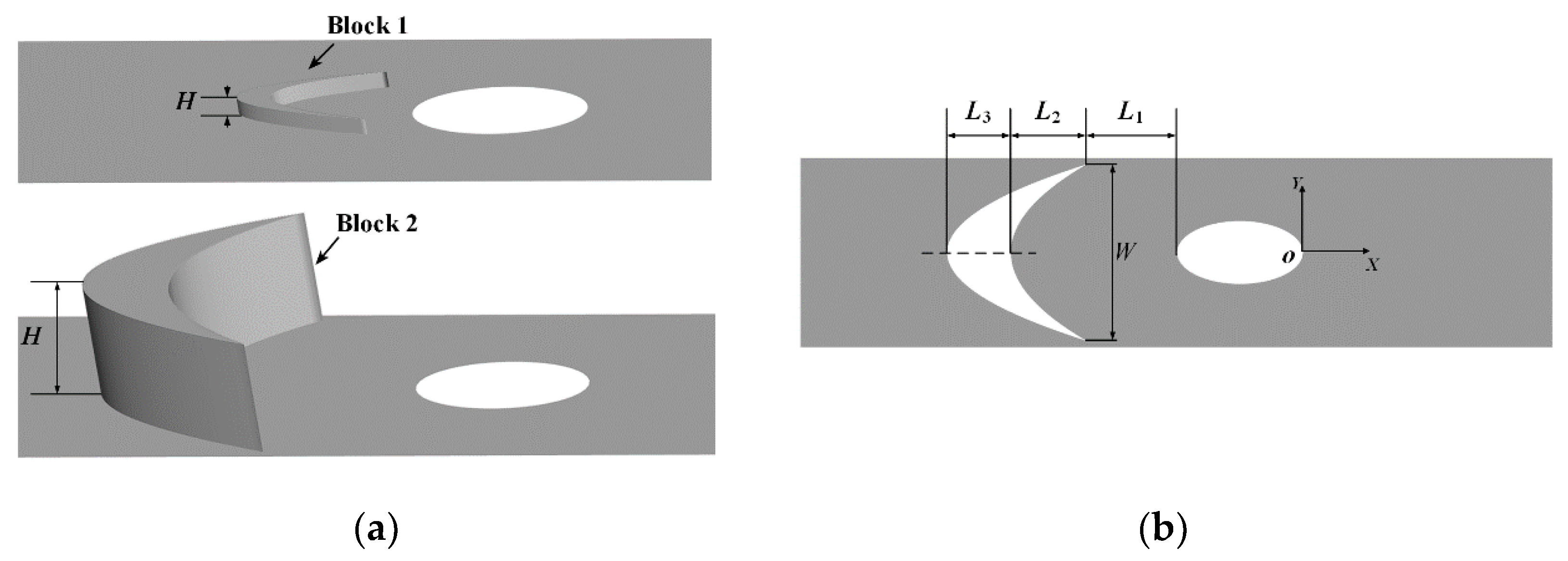
2. Geometry Model and Numerical Setup

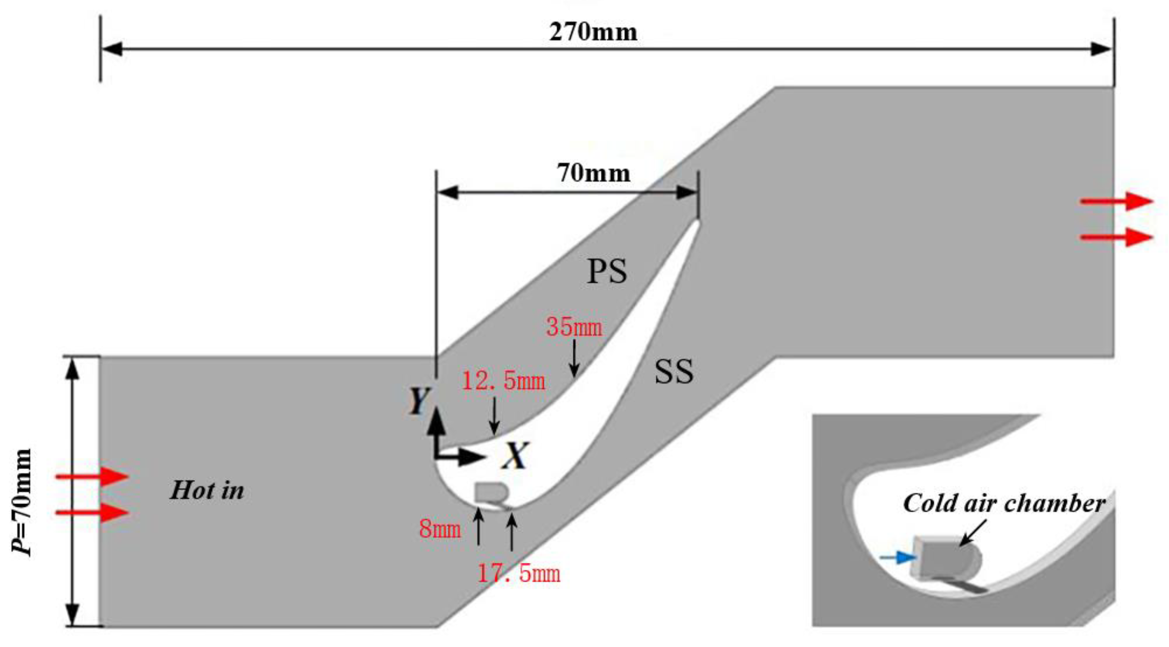
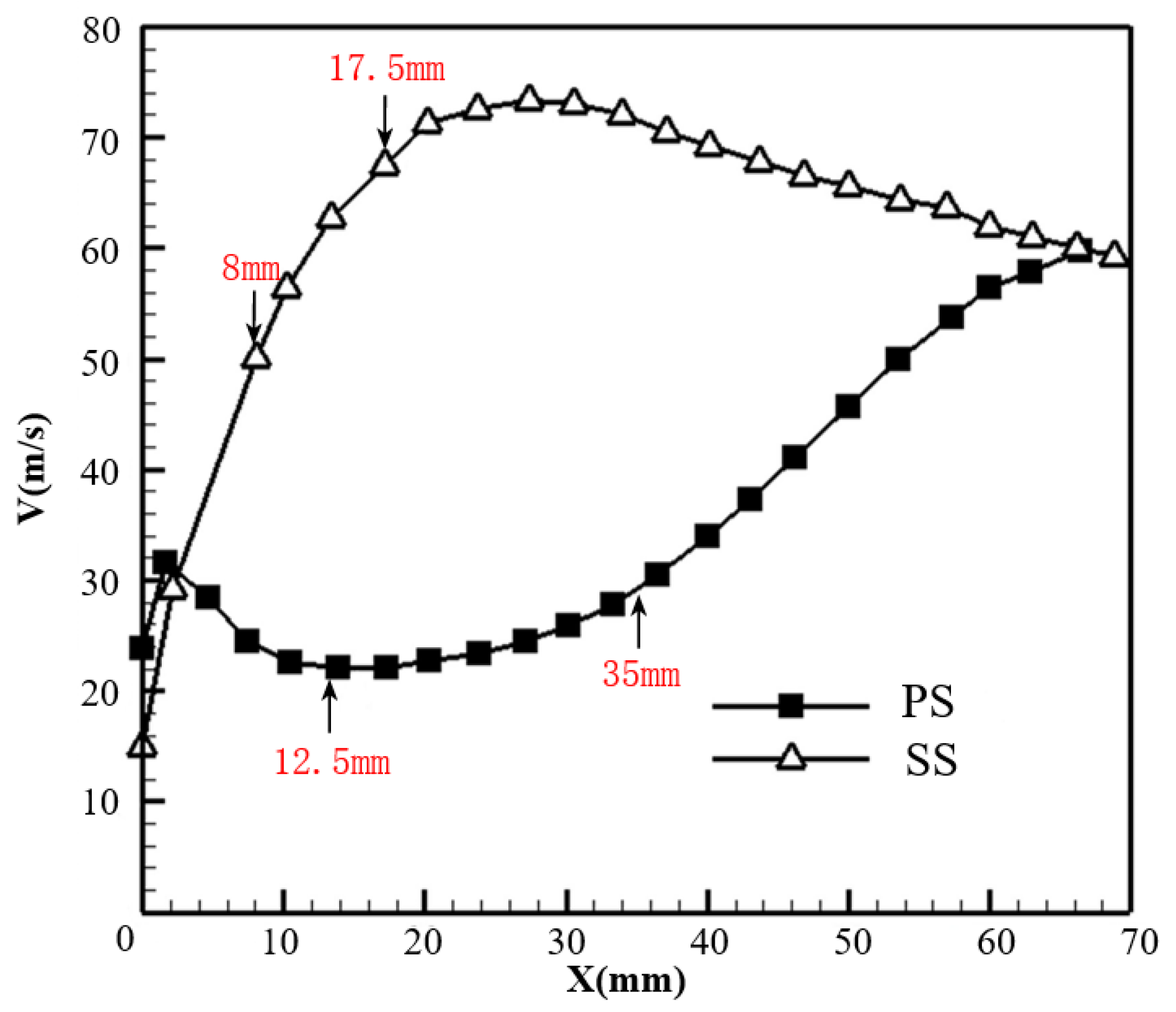
2.1. Linear Cascade Model and Boundary Conditions

The cross-view of the linear cascade with a straight blade is depicted in Figure 1. The blade profile is obtained from the mid-span section of the E3 first-stage blade. The cascade has a total streamwise length of 270 mm (direction X), a span of 70 mm (direction Y) between two adjacent blades, and a height of 3 mm (direction Z). The axial length of the turbine blade is Cx = 70 mm. The concave and convex surfaces are denoted as the pressure side (PS) and the suction side (SS).
In this study, four positions of the cylindrical cooling hole are determined to study the effect of pressure gradient and curvature according to the predicted velocity profile in Figure 2. On the pressure side, two typical locations are determined to place the cooling hole at X = 12.5 and 35 mm. The former is located at the deceleration region, and the latter is at the acceleration region. As suggested in [27], the cooling hole is commonly placed at the region in front of the blade throat on the suction side to avoid excessive aerodynamic loss. It is seen that the velocity near the suction side of the blade increases strikingly from the leading edge to the throat and decreases gradually towards the trailing edge. Two locations on the suction side are considered in front of the throat, X = 8 and 17.5 mm at the gill region. The local velocities at these four positions are listed in Table 1.
The cylindrical hole’s diameter, symbolized as D, is 1 mm. The orientation angle v.s. the local tangential direction is 30°. The total length of the cylindrical hole along the hole axis is 6D. Two crescent-shaped blocks upstream of the cylindrical hole are studied. The blocks are optimal when the blowing ratios M are 0.5 and 1.5 at the flat-plate condition in the previous work [22]. The layout of the crescent-shaped blocks is illustrated in Figure 3. The geometrical parameters of these two blocks are listed in Table 2. L1, L2, and L3 are the distances from the hole’s leading edge to the block’s trailing edge, the streamwise length of the block’s trailing edge, and the distance from the block’s leading edge to its trailing edge at the centerline, respectively. The lateral width and the height of the block are denoted as W and H, respectively.
Both the fluid in the mainflow passage and the coolant in the supply plenum are treated as the ideal air with constant thermal-physical properties. Table 3 lists the boundary conditions. Similar to the settings in [22], the temperatures at the mainstream inlet and the coolant supply plenum are Tm = 414 K and Tc = 300 K, respectively. Hence, the density ratio of coolant to hot gas is DR = 1.38. The hot gas enters the mainstream passage at the uniform velocity of Vm = 25 m/s and the turbulence intensity of 5.0%. The coolant’s turbulence intensity at the inlet of the supply plenum is set to be 1%. According to the specific blowing ratio M, the velocity at the coolant supply plenum inlet is calculated by the local velocity at the cooling hole position Vlocal, the cross area of the cylindrical hole Ahole, the density ratio DR, and the plenum inlet area Ac. The values of the local velocity Vlocal at the positions studied are referred to in Table 1. Four different blowing ratios, M = 0.5, 1.0, 1.5, and 2.0, are considered. Despite the working temperature studied here is much lower, it still makes sense by maintaining the key non-dimensional variables with similar values under real engine conditions, including DR and M.
In order to save computational cost, only one row of cooling holes with a span of 3D is taken into account with symmetric boundaries at plane Z/D = −1.5 and 1.5. Furthermore, the periodic transitional boundaries are imposed in direction Y with an interval of 70 mm to mimic the infinite turbine blades. The wall surfaces of the blade, the coolant supply plenum, the cylindrical hole, and the crescent-shaped block are considered to be smooth and adiabatic.
The local averaged cooling effectiveness η, the laterally averaged cooling effectiveness ηlat,av over the hole pitch, and the area-averaged cooling effectiveness in the downstream region 0 ≤ S/D ≤ 30 are calculated with the following equations, respectively:
η = T m T aw T m T c
η lat , av = Z = 1.5 D Z = 1.5 D η d Z
η area , av = S = 0 S = 30 D Z = 1.5 D Z = 1.5 D η d Z d S
where, Taw is the adiabatic temperature over the wall surface, and S is the arc length from the hole exit.
The dimensionless temperature θ is expressed by:
θ = T f T c T h T c
where, Tf is the temperature of the mixed flow between the hot gas and the coolant.
In addition to cooling wall surface, aerodynamic loss occurs in the mixing process between the coolant ejection and the mainstream flow, too. In our work, the total pressure loss coefficient ξtotal is adopted to evaluate the aerodynamic loss, which can be calculated as follows [28]:
ξ t o t a l = m c m c + m m p tc , in + m h m c + m m p tm , in p tm , out p tm , in p m , out
where, mc and mm are the mass flow rates of the coolant and the mainstream flow, ptc,in indicates the total pressure at the coolant plenum inlet, ptm,in and ptm,out are the total pressure at the cascade inlet and outlet, pm,out denotes the static pressure at the cascade outlet.

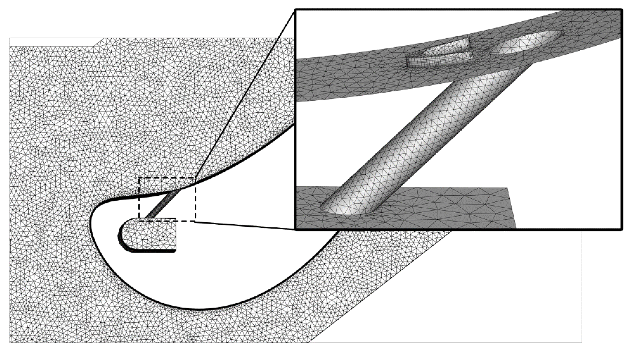
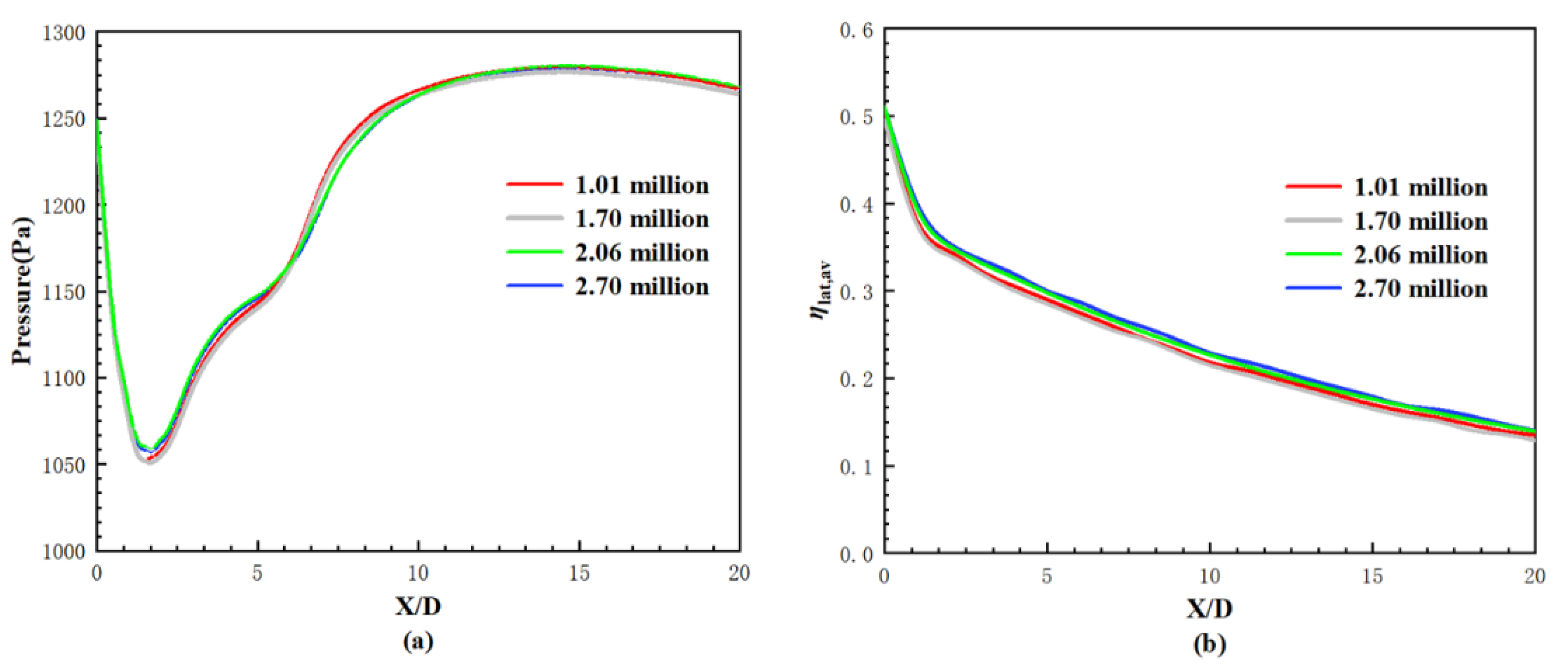
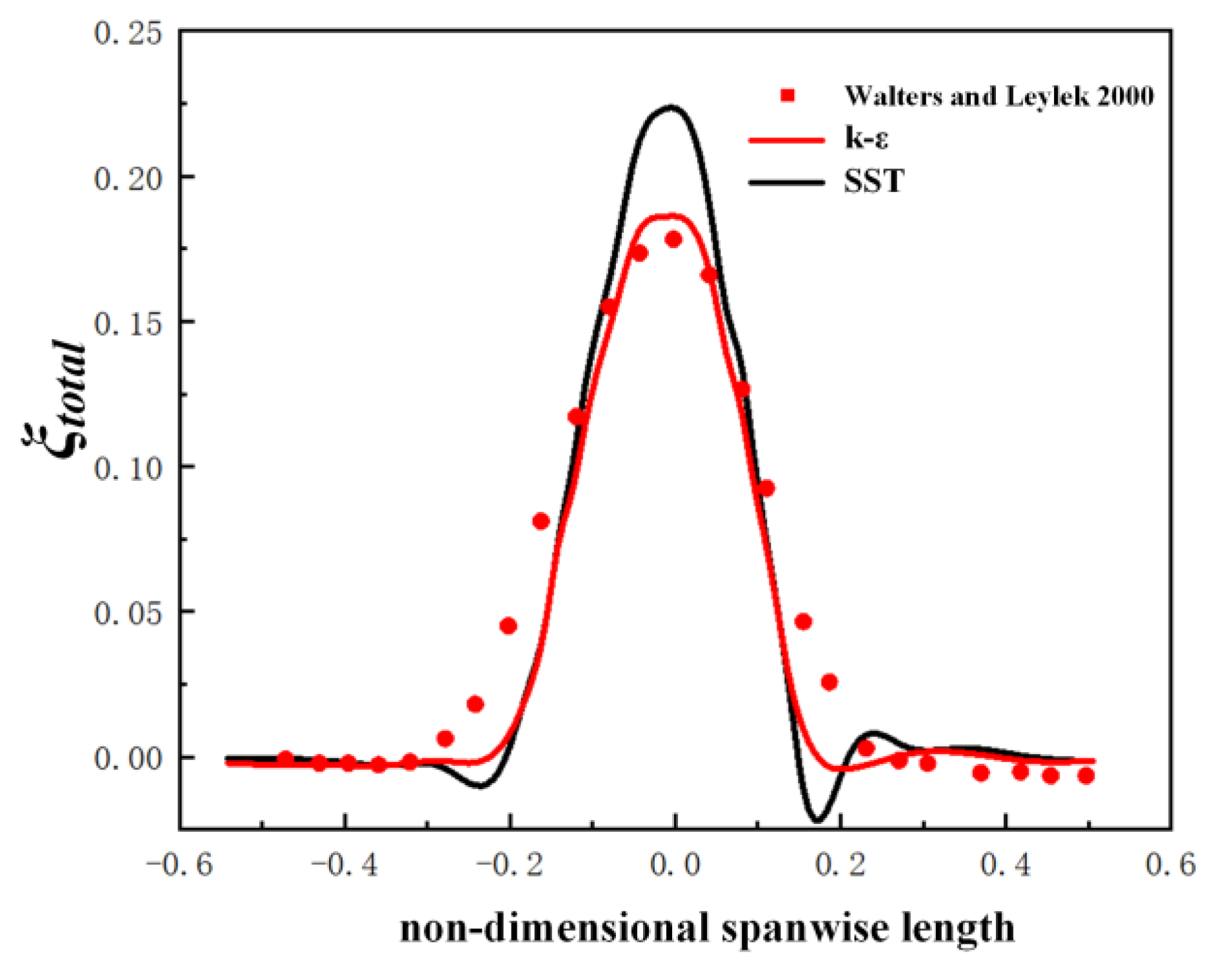
2.2. Computational Mesh and Numerical Method

A software package, ICEM CFD, is utilized to generate the unstructured mesh in the whole computational domain, shown in Figure 4. The tetrahedral mesh is applied at the mainstream passage and the coolant supply plenum. The mesh is refined near the blade surface, the cylindrical hole, and the crescent-shaped block. There are 10 prism layers around the blade surface in the mainstream passage, and the increment ratio of the prism layer is 1.2. The initial height of the prism mesh is fixed at 0.01 mm, and the corresponding values of Y+ along the pressure and suction surfaces can be seen in Figure 5. The area-averaged values of Y+ over the pressure and suction surfaces are about 1.05 and 1.42, meeting the requirement of the selected Shear Stress Transport (SST) turbulence model.
The grid independence test is checked by comparing the local pressure distribution and the laterally averaged cooling effectiveness profile at various computational grid levels. Figure 6 shows the comparison results for the cooling hole on the pressure side X = 35 mm with Block 1 at M = 0.5. Four levels of computational meshes are tested with the grid numbers of 1.01, 1.70, 2.06, and 2.70 million. While the grid number approaches 2.06 million, both the pressure and the laterally averaged cooling effectiveness ηlat,av vary slightly with further increases in grid number. Therefore, the computational grid of about 2.06 million is finally chosen for all computational cases.
Steady-state, three-dimensional, compressible turbulent mean velocity and temperature fields are modeled using the mass, momentum and energy conservation equations. The implicit finite difference scheme is applied to discrete the governing equations. When the root mean square residuals are less than 10−5, convergence is achieved. The software ANSYS CFX is used to solve the flow and cooling performance for film cooling. As a pressure-based solver, the coupled algorithm is adopted to enable the fill pressure-velocity coupling. The high-resolution scheme with the second order is applied for the discretization of the scalar equations. The continuity equation discretization uses the Rhie-Chow scheme. The numerical works [20,21,22,29] for cylindrical holes with or without the crescent-shaped block in flat-plate conditions have already shown that the predicted results of laterally averaged cooling effectiveness agree well with the experimental data in [19]. The predicted total pressure loss coefficient profile along the spanwise direction at M = 2.2 is further provided in this study compared with the experimental data in [30], demonstrated in Figure 7. It is illustrated that the k-ε turbulence model overpredicted the total pressure loss coefficient with a maximum value of 0.05, especially in the trailing edge wake region. Comparatively, the SST turbulence model agrees well with the experimental data over the entire spanwise direction. Following the previous experience of turbulent model selection and the validation of aerodynamic loss, the SST turbulence model is selected in our study for film cooling in the linear cascade.

3. Results and Discussion

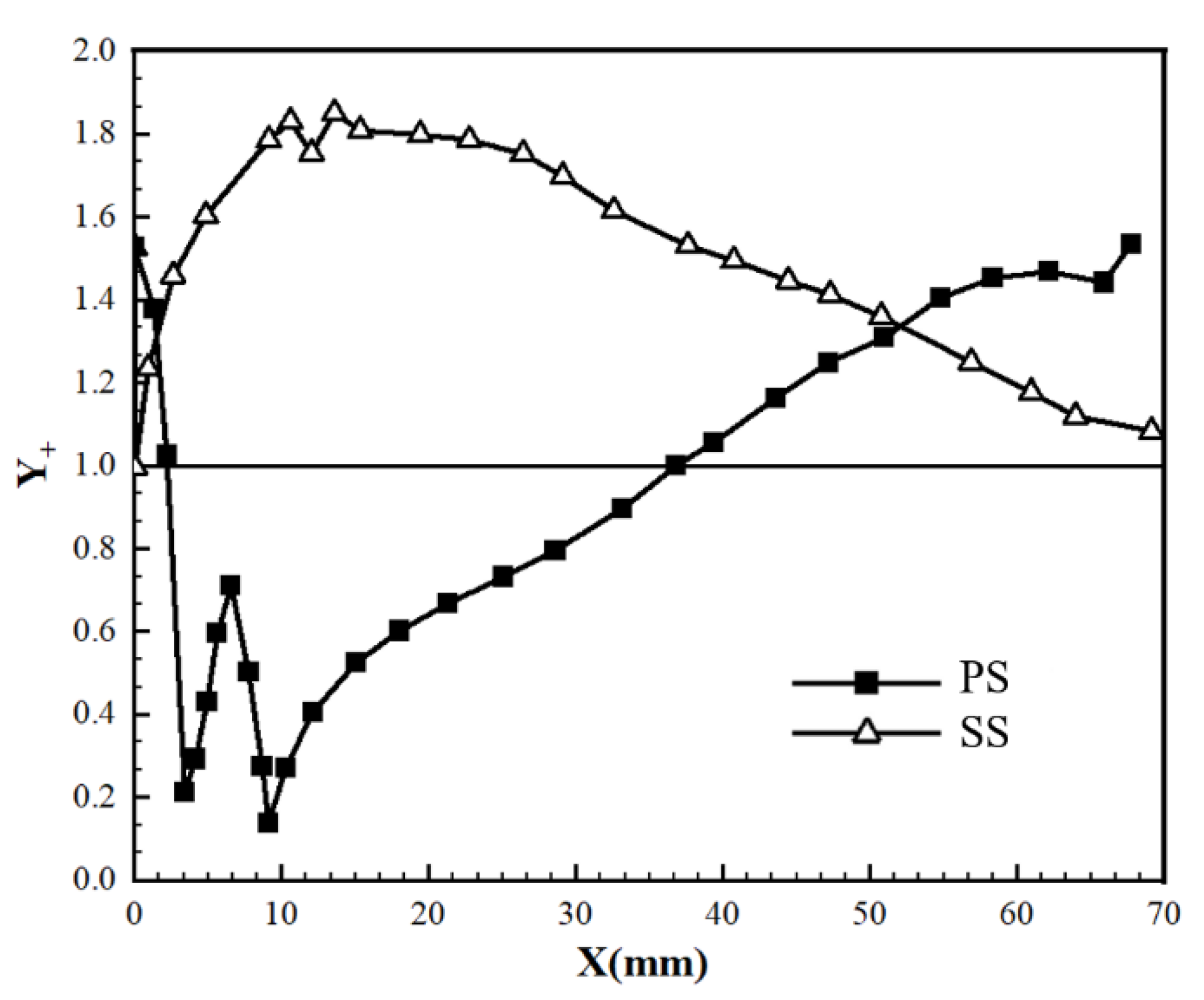
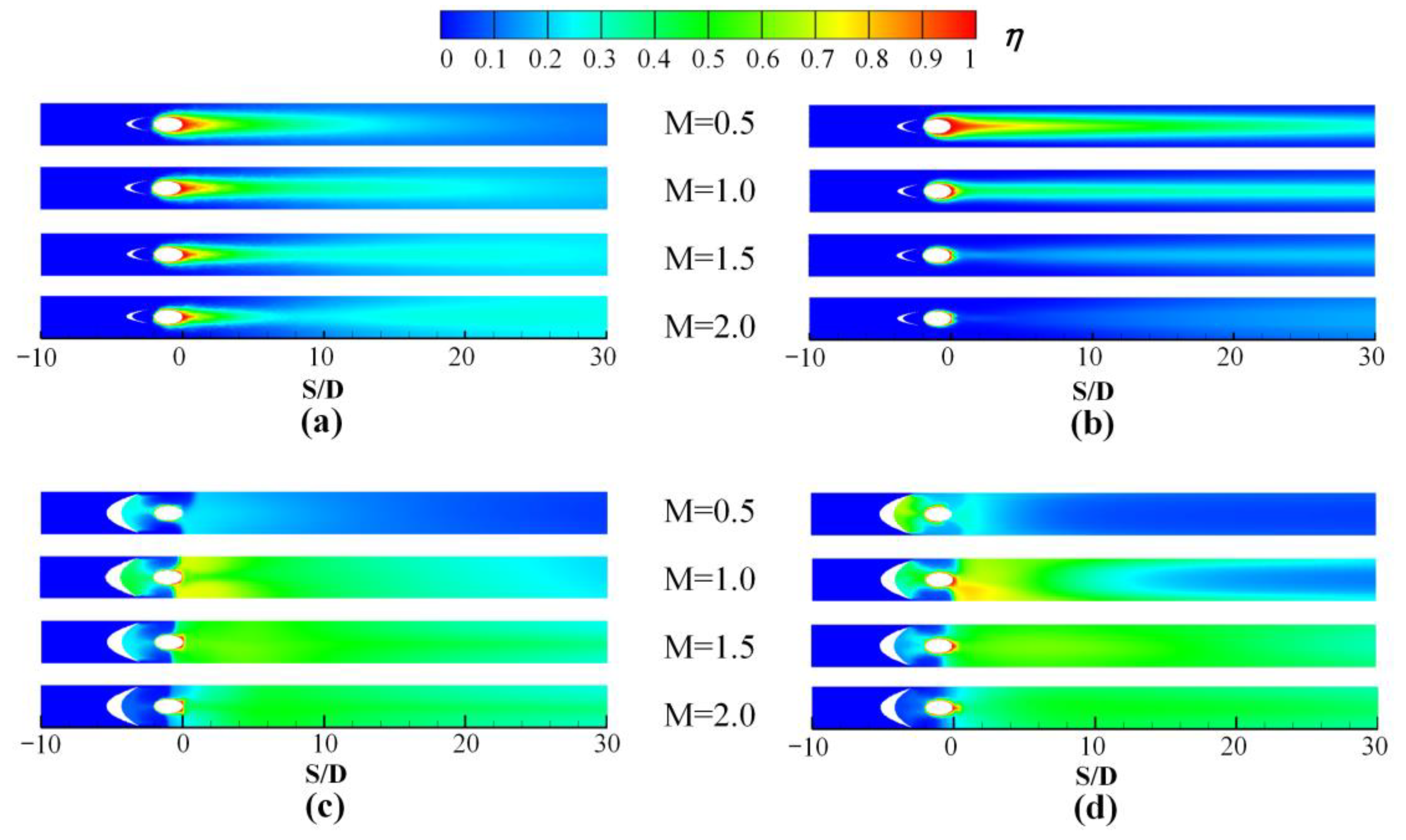
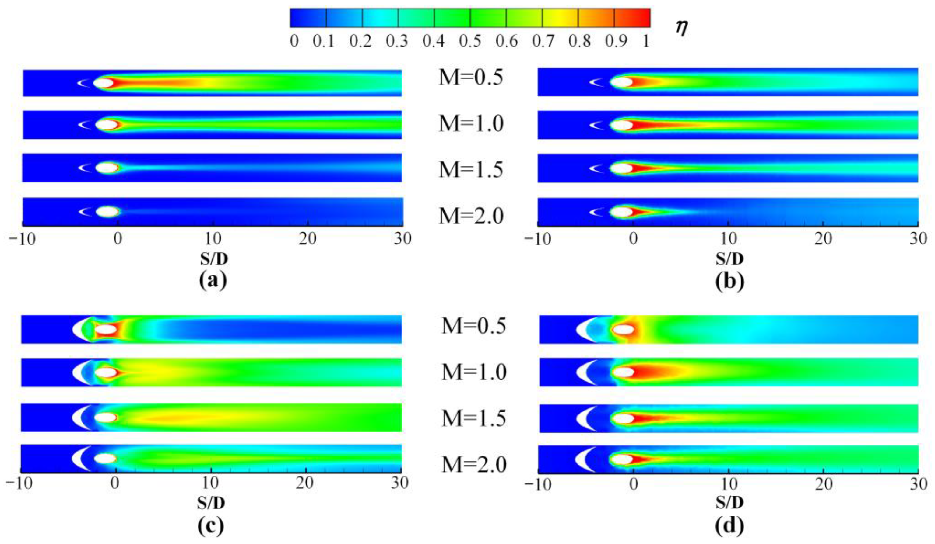
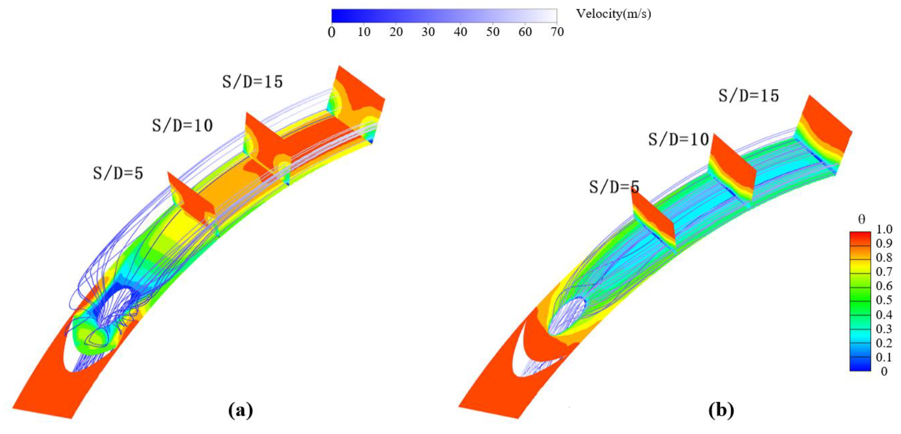
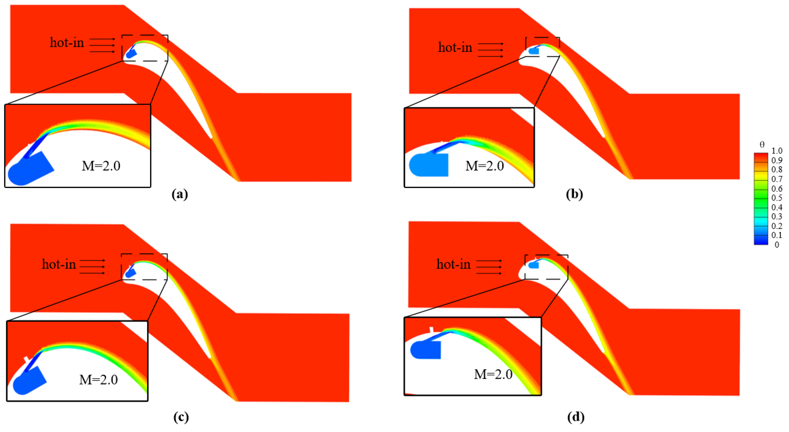
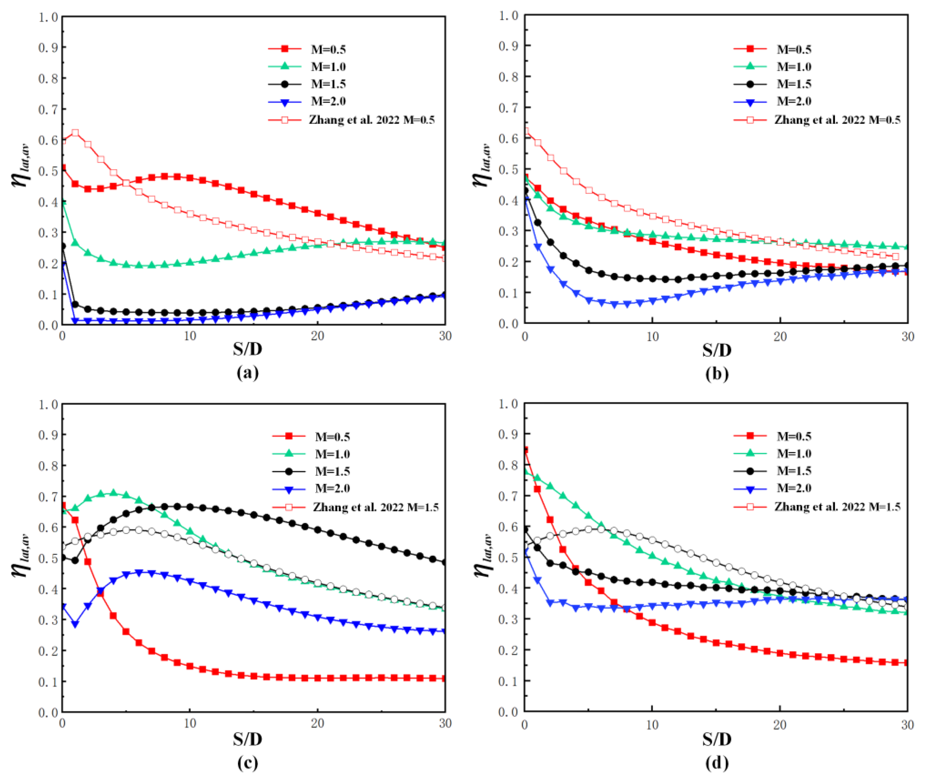
3.1. Film Cooling Performance on the Pressure Side

Figure 8 shows the contours of cooling effectiveness on the pressure side for the cooling hole located at X = 12.5 and 35 mm of Block 1 and 2. It is noted that the abscissa is set to be ratios of arc length to hole diameter S/D, and the original point is placed along the hole trailing edge for comparison. The arc length can be calculated directly from the point coordinates of the blade profile. For Block 1, higher cooling effectiveness exists at lower blowing ratios of M = 0.5–1.0 at either position. It is known that the accelerating flow benefits the coolant’s spreading along the downstream streamwise direction. Hence, the narrower but longer coolant coverage can be found for Block 1 at X = 35 mm with a slightly accelerated flow. However, as the blowing ratio increases to M = 1.5 and 2.0, Block 1 at X = 12.5 and 35 mm exhibit entirely different coolant coverage, seen in Figure 8a,b. The coolant is attached to the wall surfaces for Block 1 at X = 35 mm, for the flow momentum is lower at M = 0.5, as seen in Figure 9a. However, the coolant is lifted from the wall surface at M = 1.5 in Figure 9b due to higher flow momentum of the ejected coolant at the hole exit. Hence, the cooling performance severely deteriorates at higher blowing ratios. Furthermore, at position X = 12.5 mm, the coolant reattachment occurs nearby the location S/D =10, mainly attributed to the concave profile downstream of the hole exit.
For Block 2 with a larger dimension, the cooling effectiveness distribution at the two positions shows a minor difference at M = 1.5 and 2.0 but a larger difference at M = 0.5 and 1.0. Due to the increasing interaction between the mainstream flow and Block 2, the coolant coverage significantly improves at larger blowing ratios. The concave geometry benefits at lower blowing ratios, which can be found with higher cooling effectiveness in Figure 8c at X = 12.5 mm than that in Figure 8d at X = 35 mm. Hence, it is concluded that the impact of curvature and pressure gradient on coolant coverage depends on the specific blowing ratio and the block geometry.
The dimensionless temperature fields around the hole on the pressure side along the plane Z/D = 0 at M = 1.0 are further demonstrated in Figure 10. It is shown that the penetration depth into the mainstream flow for Block 1 at X = 35 mm is lower than that at X = 12.5 mm. The coolant flow trajectory for Block 1 at X = 35 mm displays a flatter shape. Therefore, the cooling effectiveness at the centerline is still larger at the far downstream region of X = 35 mm. Thus, the negative pressure gradient flow benefits the cooling performance for Block 1 at lower blowing ratios of M = 0.5 and 1.0. Due to the larger size of Block 2, more coolants are pushed towards the intermediate region between the cylindrical hole and the block, attributed to the stronger backward step effect. This is why the coolant cover part of the region ahead of the cylindrical hole, shown in Figure 8c,d. With the blowing ratio’s increasing, the backward step effect gradually recedes, even diminishes, and no coolant coverage occurs at M = 2.0. Furthermore, due to the negative pressure gradient at X = 12.5 mm, the coolant ejected from the hole bends along the curved surface. For Block 1 with no coolant lift-off at M = 0.5 and 1.0, the slightly reduced centerline cooling effectiveness occurs at the downstream region when the hole is located at X = 12.5 mm. However, the negative pressure gradient and the concave geometry benefit the coolant concentration around the hole and spread towards the downstream region for Block 2. Thus, the centerline cooling effectiveness is significantly higher at X = 12.5 mm compared with that at X = 35 mm.
Figure 11 further demonstrates the laterally averaged cooling effectiveness for Block 1 and 2 on the pressure and suction sides at M = 0.5–2.0. It is seen that Block 1 at X = 12.5 mm generally exhibits higher laterally averaged cooling effectiveness at the downstream region near the hole exit with the increase of the blowing ratios but rises at the far downstream area. However, for the hole of Block 1 is located at X = 35 mm, the laterally averaged cooling effectiveness decreases monotonously as the blowing ratio raises at any streamwise location in X/D = 0–30. In contrast with Block 1, the laterally averaged cooling effectiveness for Block 2 shows a different changing tendency. It reaches the lowest at M = 0.5 and becomes higher at M = 1.0. When the blowing ratios increase from 1.0 to 1.5, the laterally averaged cooling effectiveness declines at the region just downstream the hole, X < 5 at X = 12.5 mm, for example, and enhances at the residual region far from the hole. At M = 2.0, most downstream regions exhibit lower laterally averaged cooling effectiveness than that at M = 1.5. In Figure 11, the results of Block 1 at M = 0.5 and Block 2 at M = 1.5 for the flat plate film cooling are also compared. Block 1 at the pressure side has lower laterally averaged cooling effectiveness than that under the flat plate condition with a reduction of 0.1–0.15 at M = 0.5. However, the deviation for Block 2 is remarkably reduced with a value of less than 0.05 at M = 1.5.
Figure 12 displays the area-averaged cooling effectiveness of both block models at M = 0.5–2.0. When Block 1 lies at X = 12.5 mm, the area-averaged cooling effectiveness rises from 0.19 at M = 0.5 to a nearly constant value of 0.22 at M = 1.0–2.0. Block 1 at X = 12.5 mm provides a monotonic decrease of the area-averaged cooling effectiveness, and an increase of the blowing ratio from 0.24 at M = 0.5 to 0.09 at M = 2.0. For Block 2 located at these two positions, the area-averaged cooling effectiveness first rises with the blowing ratio from 0.5 to 1.5 before decreasing at the highest blowing ratio of M = 2.0. Comparatively, Block 2 has lower area-averaged cooling effectiveness at M = 0.5 at either position and higher values at M = 1.0–2.0. The greatest rises for Block 2 occur at M = 1.5 with values of 0.21 and 0.38 at X = 12.5 mm and 35 mm, respectively. Furthermore, the values for Block 1 at M = 0.5 and Block 2 at M = 1.5 under the flat plate condition are marked as red and black pentacles, respectively, shown in Figure 12. The comparison indicates that Block 1 at M = 0.5 and Block 2 at M = 1.5 on the pressure side have a 29.6–43.8% lower area-averaged cooling effectiveness than that under the flat plate condition at the corresponding blowing ratios. The disadvantage resulting from the concave surface recedes for Block 2 with larger and higher geometry, only with a decrease of 7.9% at X = 12.5 mm. Block 2 model located at X = 35 mm even gives a slightly higher area-averaged cooling effectiveness with the value of 0.5% than the flat plate film cooling hole model.

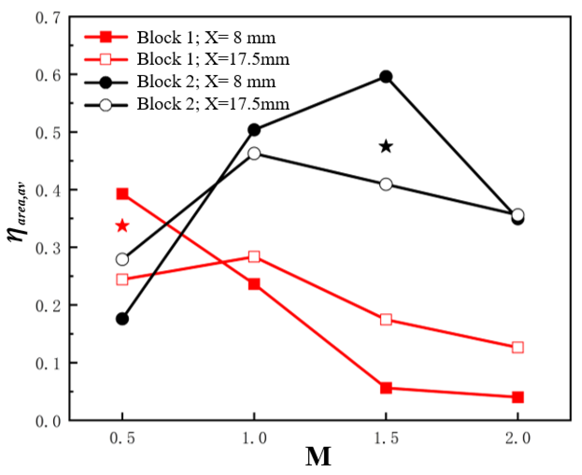
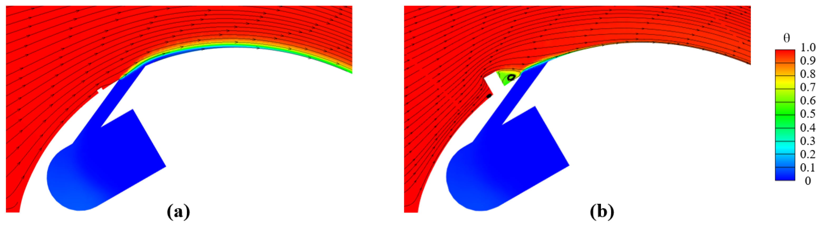
3.2. Film Cooling Performance on the Suction Side

The contours of cooling effectiveness on the suction side for Block 1 and 2 at M = 0.5–2.0 are demonstrated in Figure 13. Block 1 exhibits better coolant coverage on the suction side of the wall surfaces at lower blowing ratios of M = 0.5 and 1.0, with a remarkable reduction when the blowing ratios rise to 1.5 and 2.0. This changing trend at different blowing ratios on both the suction and the pressure sides is quite close. However, the coolant could flow towards a longer streamwise distance with the aid of the acceleration in the mainstream flow, resulting in a higher centerline cooling effectiveness at M = 0.5 and 1.0. When the blowing ratios enhance to 1.5 and 2.0, the upstream Block 1 has little effect on the ejected coolant with a larger flow momentum. The coolants are more likely to be lifted away from the wall surface due to the local convex geometry.
The coolant coverage for Block 2 is different from that for Block 1 at the same position. In general, the lateral coolant coverage over the downstream surface is greatly improved due to the stronger interaction between the mainstream and the block, and the resulting anti-kidney-shaped vortex, as reported in [22]. However, at a lower blowing ratio of M = 0.5, most coolant is dragged sideways by anti-kidney-shaped vortex and concentrated between the block and the hole, resulting in poor coolant coverage at the downstream area around the centerline, shown in Figure 14a. As the blowing ratio increases, the coolant flows evenly from the hole due to the increasing flow momentum along the streamwise direction, generating a better coolant coverage along the lateral and streamwise directions, as seen in Figure 14b. Furthermore, the backward step effect caused by Block 2 is weakened with the blowing ratios’ increasing. Hence, the coolant concentration at the downstream area of Block 2 reduces at M = 1.0 and 1.5, even diminishes at M = 2.0.
Figure 15 indicates the dimensionless temperature distribution along the plane Z/D = 0 around the block and the film cooling hole for both block models at M = 2.0. It is illustrated that the ejected coolant is detached from the downstream wall surface for Block 1 located at both positions due to its rather weak control of the ejected coolant. Furthermore, the specific separation positions are different for Block 1 at different places. The coolant detachment occurs just at the hole exit for Block 1 at X = 8 mm. However, when the hole is located at X = 17.5 mm, the coolant detachment is postponed, resulting in improved coolant coverage along the centerline, as shown in Figure 14b. For Block 2 has a larger geometry, the ejected coolant is suppressed due to the induced anti-kidney-shaped vortex with stronger intensity for the hole located at both positions, leading to a better coolant coverage in Figure 13c,d.
The profiles of laterally averaged cooling effectiveness along the downstream streamwise direction for both block models on the suction side are given in Figure 16. For Block 1 at both locations, the laterally averaged cooling effectiveness at M = 1.5 and 2.0 is lower than that at M = 0.5 and 1.0, because of the coolant departure and reduced coolant lateral coverage, as seen in Figure 13a,b. The laterally averaged cooling effectiveness at M = 1.0 is still lower than that at M = 1.0 when the hole lies at X = 8 mm. However, when the hole is placed at X = 17.5 mm, the laterally averaged cooling effectiveness at M = 1.0 is slightly lower than that at M = 0.5 at the region of S/D < 8, but higher at the region of S/D > 8. For Block 2 at X = 8 mm, the laterally averaged cooling effectiveness at M = 0.5 falls rapidly along the downstream streamwise direction from 0.68 at S/D = 0 to 0.13 at S/D = 15. A similar changing trend along the streamwise direction occurs for Block 2 at M = 0.5 from 0.85 at S/D = 0 to 0.24 at S/D = 15 when the hole is located at X = 17.5 mm. However, the variation of laterally averaged cooling effectiveness relative to S/D is gentler at M = 1.0–2.0 for Block 2 at both locations. When the hole lies at X = 8 mm, Block 2 provides higher laterally averaged cooling effectiveness at M = 1.0 and 1.5 than that at M = 0.5 and 2.0. However, when the hole is located at X = 17.5 mm, Block 2 at M = 1.0 gives higher laterally averaged cooling effectiveness at most downstream area than other blowing ratios of M = 0.5, 1.5, and 2.0. The laterally averaged cooling effectiveness under the flat plate condition for Block 1 at M = 0.5 and Block 2 at M = 1.5 are also depicted in Figure 15. Block 1 at X = 8 mm exhibits lower laterally averaged cooling effectiveness in the area of S/D < 5, but higher ones for the rest of the downstream region. However, when the hole is located at X = 17.5 mm, Block 2 on the suction side always gives lower laterally averaged cooling effectiveness than that under the flat plate condition. For Block 2, the hole at X = 8 mm still has higher laterally averaged cooling effectiveness compared with that at most downstream area under the flat plate condition, but the hole at X = 17.5 mm has lower values.
Figure 17 displays the area-averaged cooling effectiveness for Block 1 and 2 on the suction side. It is found that the highest area-averaged cooling effectiveness occurs at M = 0.5 and 1.0 for Block 1 located at X = 8 mm and 17.5 mm, respectively. However, Block 1 located at X = 17.5 mm provides lower area-averaged cooling effectiveness than that located at X = 8 mm at M = 0.5, but higher ones with the increase of 0.047–0.118 at M = 1.0–2.0. For Block 2, the highest area-averaged cooling effectiveness are 0.596 at M = 1.5 for the hole located at X = 8 mm and 0.463 at M = 1.0 for the hole located at X = 17.5 mm. At M = 0.5, Block 2 located at X = 8 mm has a lower area-averaged cooling effectiveness than that located at X = 17.5 mm. As the blowing ratios rise to M = 1.0 and 1.5, higher area-averaged cooling effectiveness occurs when the hole lies at X = 17.5 mm. The values of area-averaged cooling effectiveness for Block 2 at X = 8 mm and 17.5 mm are almost equal at M = 2.0. Furthermore, compared with the flat plate film cooling at M = 0.5, Block1 at X = 8 mm gives a 16.5% higher area-averaged cooling effectiveness, but a 27.6% lower value at X = 17.5 mm. The similar trend occurs for Block 2 at M = 1.5 in the comparison between the flat plate condition and the convex circumstance. The relative improvement at X = 8 mm is 25.6%, but the degeneration is 13.8% at X = 17.5 mm.

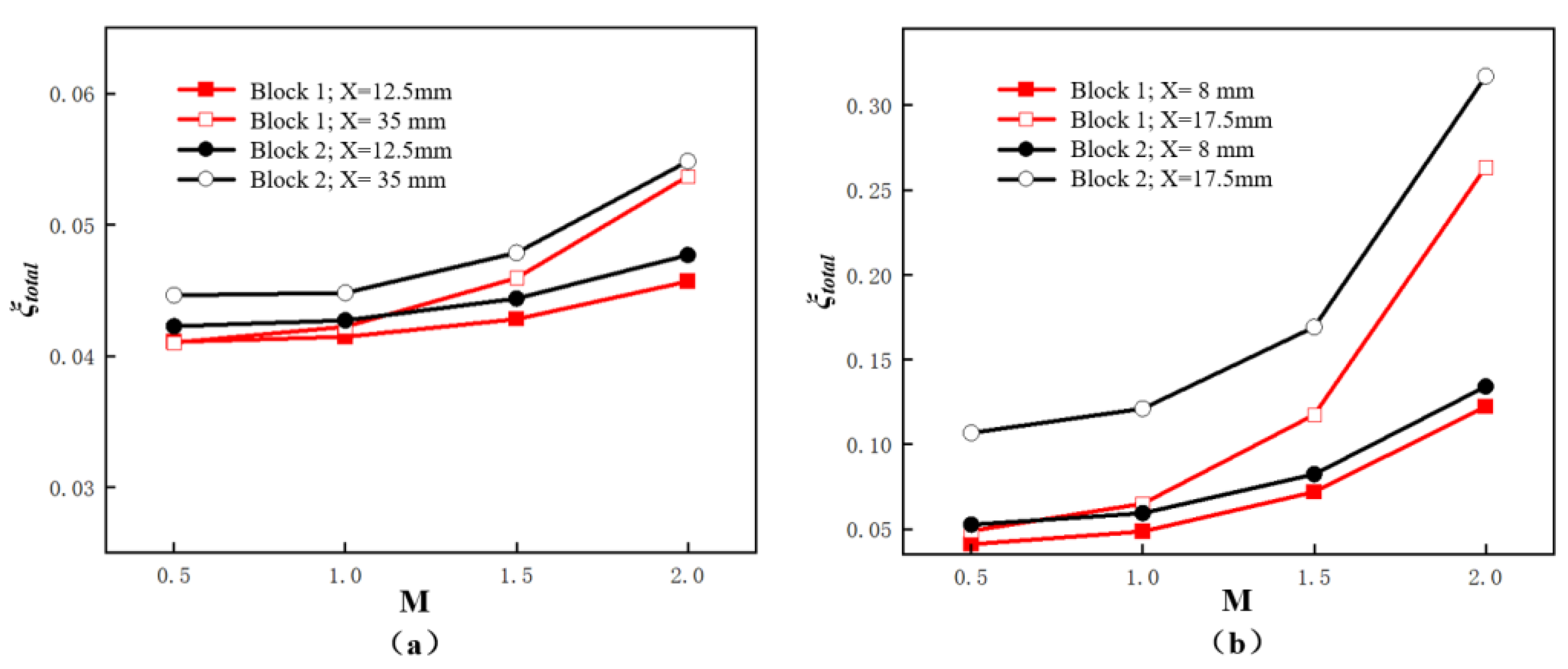
3.3. Aerodynamic Loss

Figure 18 reveals the dimensionless temperature profile and surface streamlines along the plane Z/D = 0 for both block models located on the suction side (X = 8 mm) under the blowing ratio M = 0.5. Block 1 has weak influence on the downstream flow field. By contrast, due to the large dimension of Block 2, the mainstream flow is strongly disturbed, demonstrating an obvious back-step separation flow downstream Block 2. Furthermore, the ejected coolant flow is disturbed severely by Block 2. The coolant penetration height into the mainstream flow for Block 2 is smaller than that for Block 1. Little coolant covers on the centerline, and most are squeezed sideways, as seen in Figure 14a.
The changing trends of the total pressure loss coefficient relative to the blowing ratios M = 0.5–2.0 for both block models are given in Figure 19 for the holes located on the pressure and suction sides. Generally, the total pressure loss coefficient increases monotonously with the increase of blowing ratios, regardless of the block geometry, hole location on the pressure or suction sides. This is mainly attributed to the larger mixing loss between the mainstream flow and more coolant as the blowing ratio increases. Furthermore, Block 2 always provides a higher total pressure coefficient. The higher mixing loss of Block 2 with a larger geometry is responsible for this difference. When the hole is placed on the suction side, the total pressure loss coefficient is much larger than those for the hole located on the pressure side at the same blowing ratio. This can be ascribed to more ejected coolant needed to maintain the same blowing ratio on the suction side at higher local velocity, as shown in Table 1. Furthermore, the hole on the pressure side at X = 35 mm has a higher total pressure loss coefficient than that on the pressure side at X = 12.5 mm for both block models, and the hole on the suction side at X = 17.5 mm gives higher values. The local velocity difference can also be attributed to the influence of the hole position.

4. Conclusions

In this study, numerical works were performed to investigate the cooling effectiveness, flow fields, and aerodynamic losses for the cylindrical hole with an upstream crescent-shaped block in the linear cascade. A wide variation of blowing ratios was covered from 0.5 to 2.0. The main conclusions are summarized as follows:
1. Whether the film cooling hole is located on the pressure or suction side, a similar changing trend of cooling performance for either block model occurs relative to the blowing ratio under the flat plate condition. However, the local curvature and pressure gradient influence the specific values of local cooling, laterally averaged, and area-averaged cooling effectiveness.
2. Compared with the flat plate model, Block 1 at the pressure side provides a lower area-averaged cooling effectiveness with a decrease of 29.6–43.8% at M = 0.5. The variation is significantly reduced for Block 2 at the pressure side with values of −7.9% to 0.5% at M = 1.5. However, when the block model is placed on the suction side, the relative enhancements of area-averaged cooling effectiveness at X = 8 mm are 16.5% and 25.6% for the Block 1 at M = 0.5 and Block 2 at M = 1.5. When the cooling hole is located at X = 17.5 mm on the suction side, the corresponding cooling performance is reduced with a variation of −27.6% and −13.8%, respectively.
3. Independent of the specific hole location, Block1 always shows good cooling performance at a low blowing ratio of M = 0.5, while Block 2 superiors at higher blowing ratios of M = 1.0–2.0.
4. The total pressure loss coefficients for the block models on the suction side are significantly higher than those on the pressure side due to the larger amount of ejected coolant at the same blowing ratio. The total pressure loss coefficient of suction side increases sharply with the increase of blowing ratio. Furthermore, Block 2 gives a higher total pressure loss coefficient than Block 1, mainly resulting from the stronger mixing between the larger geometry of Block 2 and the mainstream flow.

Author Contributions

Conceptualization, methodology, and writing—original draft preparation and funding acquisition, C.Z.; validation, formal analysis, data curation, and visualization, and writing—original draft preparation, J.D.; writing—review and editing, Z.W.; data curation and visualization, P.Z.; investigation, and funding acquisition; Z.T.; methodology, writing—review and editing, and supervision, Y.Z. All authors have read and agreed to the published version of the manuscript.

Funding

This research was funded by the National Natural Science Foundation of China, grant numbers 51976139 and 51506150.

Data Availability Statement

Not applicable.

Conflicts of Interest

The authors declare no conflict of interest.

References

  1. Goldstein, R.J. Film Cooling. Adv. Heat Transf. 1971, 7, 321–379. [Google Scholar]
  2. Sinha, A.K.; Bogard, D.G.; Crawford, M.E. Film-cooling effectiveness downstream of a single row of holes with variable density ratio. J. Turbomach 1991, 113, 442–449. [Google Scholar] [CrossRef]
  3. Strzelecki, A.; Gajan, P.; Gricquel, L.; Michel, B. Experimental investigation of the jets in crossflow: Nonswirling flow case. AIAA J. 2012, 47, 1079–1089. [Google Scholar] [CrossRef]
  4. Pedersen, D.R.; Eckert, E.R.G.; Goldstein, R.J. Film cooling with large density differences between the mainstream and the secondary fluid measured by the heat-mass transfer analogy. J. Heat Transf. 1977, 99, 620–627. [Google Scholar] [CrossRef]
  5. Mayhew, J.E.; Baughn, J.W.; Byerley, A.R. The effect of freestream turbulence on film cooling adiabatic effectiveness. Int. J. Heat Fluid Flow 2003, 24, 669–679. [Google Scholar] [CrossRef]
  6. Bons, J.P.; MacArthur, C.D.; Rivir, R.B. The effect of high free-stream turbulence on film cooling effectiveness. J. Turbomach. 1996, 118, 814–825. [Google Scholar] [CrossRef]
  7. Goldstein, R.J.; Eckert, E.R.G.; Burggraf, F. Effects of hole geometry and density on three-dimensional film cooling. Int. J. Heat Mass Transf. 2015, 17, 595–607. [Google Scholar] [CrossRef]
  8. Saumweber, C.; Schulz, A. Free-stream effects on the cooling performance of cylindrical and fan-shaped cooling holes. J. Turbomach. 2012, 134, 061007. [Google Scholar] [CrossRef]
  9. Bunker, R.S. Film cooling effectiveness due to discrete holes within a transverse surface slot. In Proceedings of the ASME Turbo Expo 2002: Power for Land, Sea, and Air, Amsterdam, The Netherlands, 3–6 June 2002; Volume 3. [Google Scholar]
  10. Lu, Y.P.; Ekkad, S.V. Film cooling measurements for cratered cylindrical inclined holes. J. Turbomach. 2009, 131, 011005. [Google Scholar] [CrossRef]
  11. Dorrington, J.R.; Bogard, D.G.; Bunker, R.S. Film effectiveness performance for coolant holes embedded in various shallow trench and crater depressions. In Proceedings of the ASME Turbo Expo 2007: Power for Land, Sea, and Air, Montreal, QC, Canada, 14–17 May 2007; Volume 4. [Google Scholar]
  12. Fric, T.F.; Roshko, A. Vortical structure in the wake of a transverse jet. J. Fluid Mech. 1994, 279, 1–47. [Google Scholar] [CrossRef] [Green Version]
  13. Kusterer, K.; Bohn, D.; Sugimoto, T.; Tanaka, R. Double-jet ejection of cooling air for improved film cooling. J. Turbomach. 2007, 129, 809–815. [Google Scholar] [CrossRef]
  14. Kusterer, K.; Elyas, A.; Bohn, D.; Sugimoto, T.; Tanaka, R.; Kazari, M. Film cooling effectiveness comparison between shaped- and double jet cooling holes in a row arrangement. In Proceedings of the ASME Turbo Expo 2010: Power for Land, Sea, and Air, Glasgow, UK, 14–18 June 2010; Volume 4. [Google Scholar]
  15. Nasir, H.; Acharya, S.; Ekkad, S. Improved film cooling from cylindrical angled holes with triangular tabs: Effect of tab orientations. Int. J. Heat Fluid Flow 2003, 24, 657–668. [Google Scholar] [CrossRef]
  16. Na, S.; Shih, T.I.-P. Increasing adiabatic film-cooling effectiveness by using an upstream ramp. J. Heat Transf. 2007, 129, 464–471. [Google Scholar] [CrossRef]
  17. Kawabata, H.; Funazaki, K.; Nakata, R.; Takahashi, D. Experimental and numerical investigations of effects of flow control devices upon flat-plate film cooling performance. J. Turbomach. 2014, 136, 061021. [Google Scholar] [CrossRef]
  18. Zhou, W.W.; Hu, H. A novel sand-dune-inspired design for improved film cooling performance. Int. J. Heat Mass Transf. 2017, 110, 908–920. [Google Scholar] [CrossRef] [Green Version]
  19. An, B.T.; Liu, J.J.; Zhang, C.; Zhou, S.J. Film cooling of cylindrical hole with a downstream short crescent-shaped block. J. Heat Transf. 2013, 135, 031702. [Google Scholar] [CrossRef]
  20. Zhang, C.; Wang, Z. Influence of streamwise position of crescent-shaped block on flat-plate film cooling characteristics. J. Braz. Soc. Mech. Sci. Eng. 2019, 41, 499. [Google Scholar] [CrossRef]
  21. Zhang, C.; Bai, L.C.; Zhang, P.F. Sensitivity analysis of the film-cooling effectiveness of an upstream crescent-shaped vortex generator to geometric parameters. J. Eng. Phys. Thermophys. 2021, 94, 1137–1146. [Google Scholar] [CrossRef]
  22. Zhang, P.F.; Zhang, C.; Wang, Z. Optimization of crescent-shaped block upstream of the cylindrical hole to enhance film cooling effectiveness using CFD and genetic algorithm. Prog. Comput. Fluid Dyn 2022. Accepted. [Google Scholar]
  23. Schwarz, S.G.; Goldstein, R.J.; Eckert, E.R.G. The influence of curvature on film cooling performance. J. Turbomach. 1991, 113, 472–478. [Google Scholar] [CrossRef]
  24. Ligrani, P.; Goodro, M.; Fox, M.; Moon, H.K. Full-coverage film cooling effectiveness and heat transfer coefficients for dense hole arrays at different hole angles, contraction ratios, and blowing ratios. J. Heat Transf. 2013, 135, 031717. [Google Scholar] [CrossRef]
  25. Kawabata, H.; Funazaki, K.; Suzuki, Y.; Tagawa, H.; Horiuchi, Y. Improvement of turbine vane film cooling performance by double flow-control devices. J. Turbomach. 2016, 138, 111005. [Google Scholar] [CrossRef]
  26. Zhang, P.F. Investigation on Flow and Cooling Characteristics of Cylindrical Film Cooling Hole with Block. Master’s Thesis, Tianjin University of Technology, Tianjin, China, 2022. [Google Scholar]
  27. Wang, L.; Luo, J.; Tian, S.; Zhu, H.; Liu, C. Film cooling performance comparison at different positions on blade suction side. J. Aerosp. Power 2017, 32, 1281–1288. [Google Scholar]
  28. Liu, J.J.; Lin, X.C.; Zhang, X.D.; An, B.T. Investigation on cooling effectiveness and aerodynamic loss of a turbine cascade with film cooling. J. Therm. Sci. 2016, 25, 50–59. [Google Scholar] [CrossRef]
  29. Zhang, C.; Wang, W.W.; Wang, Z.; Tong, Z.T. Conjugate heat transfer simulation of overall cooling performance for cratered film cooling holes. Machines 2022, 10, 395. [Google Scholar] [CrossRef]
  30. Walters, D.K.; Leylek, J.H. Impact of film-cooling jets on turbine aerodynamic losses. J. Turbomach. 2000, 122, 537–545. [Google Scholar] [CrossRef]
Figure 1. The sketch of the linear cascade.
Machines 11 00110 g001
Figure 2. Velocity profile around the blade surfaces.
Machines 11 00110 g002
Figure 3. The crescent-shaped block. (a) Layout; (b) Top view.
Machines 11 00110 g003
Figure 4. Computational mesh.
Machines 11 00110 g004
Figure 5. Variation of Y+ values over the pressure and suction surfaces.
Machines 11 00110 g005
Figure 6. Comparisons with different levels of computational grid (a) pressure; (b) laterally averaged cooling effectiveness.
Machines 11 00110 g006
Figure 7. Validation of the turbulence model [30].
Machines 11 00110 g007
Figure 8. Contours of cooling effectiveness at M = 0.5–2.0 at the pressure side. (a) Block 1, X = 12.5 mm; (b) Block 1, X = 35 mm; (c) Block 2, X = 12.5 mm; (d) Block 2, X = 35 mm.
Machines 11 00110 g008
Figure 9. Dimensionless temperature distribution and streamlines for Block 1 at X = 35 mm. (a) M = 0.5; (b) M = 1.5.
Machines 11 00110 g009
Figure 10. Dimensionless temperature distribution along plane Z/D = 0 at M = 1.0. (a) PS Block 1, X = 12.5 mm; (b) PS Block 1, X = 35 mm; (c) PS Block 2, X = 12.5 mm; (d) PS Block 2, X = 35 mm.
Machines 11 00110 g010
Figure 11. Laterally averaged cooling effectiveness on the pressure side [22]. (a) PS Block 1, X = 12.5 mm; (b) PS Block 1, X = 35 mm; (c) PS Block 2, X = 12.5 mm; (d) PS Block 2, X = 35 mm.
Machines 11 00110 g011
Figure 12. Area averaged cooling effectiveness relative to blowing ratios on the pressure side.
Machines 11 00110 g012
Figure 13. Local Cooling effectiveness distribution on the suction side. (a) SS Block 1, X = 8 mm; (b) SS Block 1, X = 17.5 mm; (c) SS Block 2, X = 8 mm; (d) SS Block 2, X = 17.5 mm.
Machines 11 00110 g013
Figure 14. Dimensionless temperature and streamlines for Block 2 at X = 8 mm. (a) M = 0.5; (b) M = 1.5.
Machines 11 00110 g014
Figure 15. Dimensionless temperature distribution along the plane Z/D = 0 at M = 2.0. (a) SS Block 1, X = 8 mm; (b) SS Block 1, X = 17.5 mm; (c) SS Block 2, X = 8 mm; (d) SS Block 2, X = 17.5 mm.
Machines 11 00110 g015
Figure 16. Laterally averaged cooling effectiveness on suction sides [22]. (a) Block 1, X = 8 mm; (b) Block 1, X = 17.5 mm; (c) Block 2, X = 8 mm; (d) Block 2, X = 17.5 mm.
Machines 11 00110 g016
Figure 17. Area averaged cooling effectiveness v.s. blowing ratios on the suction side.
Machines 11 00110 g017
Figure 18. Dimensionless temperature profile and surface streamlines along the plane Z/D = 0 at M = 0.5 (a) SS Block 1, X = 8 mm; (b) SS Block 2, X = 8 mm.
Machines 11 00110 g018
Figure 19. Total pressure loss coefficient relative to blowing ratios. (a) On the pressure side; (b) On the suction side.
Machines 11 00110 g019
Table 1. Local curvature and velocity at the hole location.
Hole LocationLocal Velocity Vlcoal (m/s)
PS, X = 12.5 mm22.0
PS, X = 35 mm29.3
SS, X = 8 mm51.7
SS, X = 17.5 mm68.5
Table 2. Geometrical parameters of the crescent-shaped block.
Block No.L1/DL2/DL3/DW/DH/D
Block 10.41.20.41.00.2
Block 21.41.21.02.81.4
Table 3. Boundary conditions.
ParameterMainstream PassageCoolant Supply Plenum
Inlet temperatureTm = 414 KTc = 300 K
Inlet velocityVm = 25 m/sVc = M·Vlocal·Ahole/(DR·Ac)
Inlet turbulence intensity5%1%
Outlet static pressure0.1 MPa-
Disclaimer/Publisher’s Note: The statements, opinions and data contained in all publications are solely those of the individual author(s) and contributor(s) and not of MDPI and/or the editor(s). MDPI and/or the editor(s) disclaim responsibility for any injury to people or property resulting from any ideas, methods, instructions or products referred to in the content.

