Article

An Equilibrium Decision-Making Approach for Cutting Parameters of a Novel Five-Axis Hybrid Kinematic Machining Unit

1
The State Key Laboratory of Mechanical Transmissions, Chongqing University, Chongqing 400044, China
2
School of Mechanical Engineering and Automation, Fuzhou University, Fuzhou 350116, China
3
Capital Aerospace Machinery Corporation Limited, Beijing 100076, China
*
Author to whom correspondence should be addressed.
Machines 2022, 10(9), 824; https://doi.org/10.3390/machines10090824
Submission received: 5 August 2022 / Revised: 14 September 2022 / Accepted: 15 September 2022 / Published: 19 September 2022
(This article belongs to the Topic Robotics and Automation in Smart Manufacturing Systems)

Abstract

:
To fully disclose the machining potential of a newly developed five-axis hybrid kinematic machining unit (HKMU), an equilibrium decision-making approach for cutting parameters is proposed. With this proposition, a response surface method-based surrogate model is developed to describe the mapping relationships between three design objectives and five cutting parameters. A multi-objective optimization model is further established to find feasible Pareto solutions to cutting parameters. Based on this, the technique for order preference by similarity to ideal solution (TOPSIS) and engineering decision preferences are adopted to make the final decision of cutting parameters. To illustrate the application of the proposed approach, a case study is carried out on face milling of an exemplary HKMU. The equilibrium decisions of three customized machining schemes lead to the machining duration, the cutting force, and the surface roughness reduction by 44%, 43%, and 9%, respectively. This result supports that the proposed equilibrium decision-making approach is able to find the best-compromised solutions for cutting parameters of the HKMU. It is expected that with minor modifications, the proposed approach can be applied to other multi-axis machining devices for finding accurate yet efficient cutting parameter solutions.

1. Introduction

Hybrid kinematic machining units (HKMUs) with five-axis machining ability have been proposed as a kind of supplement to traditional five-axis machine tools and multi-axis articulated machining robots [1,2,3,4]. From a topological view, an HKMU is constructed as a serial-parallel hybridized mechanism which may promote the merits and complement the shortcomings of individual parallel and serial mechanisms [5,6,7]. Hence, HKMUs have been regarded as a promising alternative solution for efficient five-axis machining in many industrial fields [8,9,10]. Examples of commercially successful HKMUs include the famous Tricept robot [11], the Eco-speed machining center [12], and the Exechon machine tool [13]. Inspired bythese successful examples, the authors recently proposed a novel five-axis HKMU by integrating a redundantly actuated parallel manipulator with two translational sliding gantries [14]. Our previous studies indicate that thiskind of HKMU has the conceptual advantages of compact structure, better dexterity, and a larger workspace volume ratio [15,16]. Untilnow, the determination of cutting parameters for the proposed HKMU was dependent on the user’s engineering experience. Therefore, it is of great necessity to construct an appropriate decision-making approach to fully disclose the machining potential and to find the best cutting parameters for the HKMU before it is employed as a precision machining device.
There are three aspects involved in the issue of cutting parameter determination. The first issue is how to determine design criteria to evaluate cutting performances quantitatively. The second issue is how to describe the relationships between design objectives and cutting parameters. The third issue is how to implement multi-objective optimization for designating final decisions.
As to the first aspect, there are plentiful design criteria. The most commonly used are material removal rate, cutting force, surface roughness, machining accuracy, power consumption, tool life, and service performances, which can be estimated either by explicit formulations or experimental measurements [17,18,19,20,21]. When applying these criteria to cutting performance evaluation, there are two main forms, i.e., single-objective approaches and multi-objective approaches. To be specific, a single-objective approach focuses on a certain design criterion in the machining process, such as surface roughness-oriented optimization design [22]. However, this limited evaluation dimension does not reflect cutting characteristics comprehensively. Thus, multi-objective approaches are proposed to adopt more than one design criteria, which enable different, even contradictory, cutting objectives to be taken into consideration simultaneously [23,24,25,26]. This eventually leads to more comprehensive results meeting multiple requirements, including production efficiency, machining stability, and cutting quality. In view of this, it is preferable to adopt multiple criteria, such as machining duration, cutting force, and surface roughness, to comprehensively evaluate the cutting performances of an HKMU.
As for the second aspect, its primary task is to construct a mapping model to describe the cutting performance relationship. According to the described manners, the mapping models for handling cutting performances can be roughly divided into two categories, i.e., analytical models [27,28] and surrogate models [29,30]. To be specific, analytical models aim to explicitly deconstruct the interaction/transmission mechanism between the force and the energy in the cutting process. Constructing an efficient analytical model mostly relies on appropriate assumptions and delicate procedures [31]. This may bring out difficulties in mapping modeling and limit computational efficiency. Different from the analytical model, surrogate models usually approximate the cutting performance mapping by combining the response surface method (RSM) with design of experiments (DoE) [32]. Thus, a surrogate model can be regarded as a kind of data-based model with concise expression, which can be directly called in the iterative calculation of the mapping model. This characteristic may reduce the difficulty of modeling and improve the computational efficiency of a cutting performance model [33]. Hence, the surrogate model provides a promising solution for describing the cutting processes of an HKMU.
As to the third aspect, there are mainly two kinds of methods available for multi-objective optimization of cutting parameters. The first is the weighted sum method, which uses a set of customized weights to transform a multi-objective problem into a traditional single-objective problem [34,35,36]. Then, a linear programming approach can be adopted to solve the transformed problem to obtain optimized solutions. However, the selection of weights usually lacks a reasonable and quantitative basis. Additionally, the weighted sum method may encounter difficulties and make optimized results less applicable when there are non-convex or disconnected regions in the design space [37]. Different from the first method, the second method treats a multi-objective problem as a nonlinear multivariate programming problem [38]. By applying this type of method, all design objectives are simultaneously optimized. Accordingly, not one best-optimized solution, but a cluster of compromised solutions called the Pareto frontier, is obtained [39]. In view of this, the analytic hierarchy process (AHP) [40], the technique for order preference by similarity to ideal solution (TOPSIS) [41], and their variants [42,43] are adopted to determine the best-compromised solution. Both approaches attempt to convert multidimensional objects into a single sequence for decision convenience. To be specific, AHP uses the logical grading system to compare various alternatives [42], while TOPSIS directly assesses the relative closeness of Pareto solutions to the ideal optimum [43]. In addition, for a real-world machining task, the decision maker’s preferences often need to be taken into account to meet customized requirements [44]. Therefore, combining the TOPSIS technique with engineering decision preferences is necessary for final decisions on the cutting parameters of an HKMU.
The present study aims to develop an equilibrium decision-making approach for cutting parameters of HKMUs. For this purpose, an RSM-based surrogate model is built for mapping the cutting performances of an HKMU. A multi-objective optimization model is established for determining the Pareto solutions of cutting parameters. Based on this, both the TOPSIS technique and engineering decision preferences are adopted to achieve an equilibrium decision on the cutting parameters of an HKMU. With the proposed approach, the final solution of cutting parameters of an HKMU is no longer merely left to engineers’ experience but results from both technological considerations and end users’ dimensions. The rest of this paper is organized as follows. In Section 2, design objectives, the RSM-based surrogate model, and the multi-objective optimization model are successively established for developing the equilibrium decision-making approach for cutting parameters. In Section 3, a novel HKMU with five-axis machining capacity is taken as an example to illustrate the application of the proposed equilibrium decision-making approach. Finally, some conclusions and remarks are presented in Section 4.

2. Equilibrium Decision-Making Approach

In general, the multiple design criteria in the cutting process, such as production efficiency, machining stability, and cutting quality, are dependent on each other. In other words, the improvement of one of them always leads to the worsening of another one. Hence, the decision-making on cutting parameters of an HKMU is, in essence, a trade-off problem between the design requirements of the cutting process. To deal with this issue, an equilibrium decision-making approach is proposed.
As outlined in Figure 1, the main idea of the proposed approach is to transform the trade-off problem into a multi-objective optimization with the objectives of machining duration, cutting force, and surface roughness. To implement the multi-objective optimization, an RSM-based surrogate model is adopted to describe the relationships between design objectives and cutting parameters. Herein, the three design objectives of machining duration, cutting force, and surface roughness are considered together. Five important cutting parameters, such as spindle speed, tool diameter, depth of cut, width of cut, and feed rate, are equally adopted in this decision-making process. Following this framework, a flowchart of the equilibrium decision-making approach is presented in Figure 2.
As shown in Figure 2, there are four main steps.
(1)
Firstly, the design objectives and cutting parameters of an HKMU are determined on the basis of the design criteria of the specified initial machining task.
(2)
Secondly, DoE is carried out to collect cutting responses. Based on this, the RSM technique [32] is adopted to establish a surrogate model in an accurate yet efficient manner. The surrogate model will be assessed in terms of regression accuracy, indicating whether it is acceptable for the following optimization.
(3)
Then, the acceptable surrogate model, as well as design constraints and boundary conditions, are employed in the multi-objective optimization design. By simultaneously optimizing the multiple objective functions, a cluster of solutions called the Pareto frontier is obtained for cutting parameters.
(4)
Finally, by combining the TOPSIS technique [41] and engineering decision preferences, a set of decision-making procedures is proposed to designate the best-compromised solution from the Pareto solutions.
As a result, the main advantage of this decision approach may lie in taking both technological considerations and end users’ dimensions into the final solution of cutting parameters of an HKMU.

2.1. Objectives of Cutting Process

For clarity, the mathematical expression of the design objectives, such as machining duration, cutting force, and surface roughness, is formulated as follows.
(1)
Machining duration Te
For the sake of measurement convenience, the machining duration Te of a cutting process is computed by the expression:
T e = i = 1 n T s i
where Tsi (i = 1, 2,…, n) denotes the average duration of the ith machining step; n is the total number of machining steps in a machining duration.
(2)
Cutting force Fc
To reflect the variation of the cutting force in the whole machining process more comprehensively, the cutting force of a workpiece is estimated by average cutting forces along three coordinate axes. Thus, the cutting force is defined as:
F c = 1 T e ( T d F d x 2 + F d y 2 + F d z 2 + T u F u x 2 + F u y 2 + F u z 2 )
where Td and Tu denote the machining durations of the down cutting and the up cutting, respectively; Fdx, Fdy, and Fdz and Fux, Fuy, and Fuz represent the average cutting forces along three coordinate axes in the process of down cutting and up cutting, respectively.
(3)
Surface roughness Ra
In practice, the roughness measurements of a machined work piece are usually taken from n sampling points for convenience. The average value of the n sampling points is recorded as the final value of the roughness.
R a = 1 n i = 1 n R a i
where Rai denotes the roughness value of the i-th (i = 1, 2,…, n) sampling point on the machined workpiece.
From the above-presented expressions, it can be found that a smaller value of [Te], [Fc], and [Ra] means higher efficiency, stability, and quality in the cutting process of an HKMU, respectively. However, it’s hard to analytically describe the mapping relationships between these design objectives and corresponding cutting parameters [31]. Fortunately, surrogate methods provide a solution to directly characterize such mapping relationships with concise expression and acceptable efficiency [32].

2.2. RSM-Based Surrogate Model

The RSM technique is an efficient mathematical tool for building a surrogate model for mapping cutting parameters. The establishment of the RSM-based surrogate model is summarized in the following steps.
(1)
According to the dimensions of objectives and variables, select an experimental strategy that has as much information yet implementation convenience.
(2)
With the help of commercial software such as Design Expert or Isight, collect and manage the multiple responses to the design objectives of the cutting process.
(3)
On the basis of the statistical features obtained from experimental data, estimate the regression coefficients to fit the response surface of data.
For engineering practices, the commonly used response surface model can be mathematically described as:
y ( x ) = α 0 + i = 1 p β i x i + i = 1 p β i i x i 2 + i = 1 p i < j p β i j x i x j + i = 1 p γ i x i 3 + i = 1 p i j p γ i j ( x i ) 2 x j + i = 1 p i < j < k p γ i j k x i x j x k
where y ( x ) is the fitting function of the response surface model of a design objective; x = [ x 1 x 2 x p ] T is the p-dimensional cutting parameters; α 0 , β i , β i i , β i j , γ i , γ i i and γ i j k denote the estimated regression coefficients, respectively.
Before determining an appropriate surrogate model for optimization design, the regression accuracy of response surface models should be evaluated. To assess the model accuracy, three metrics, namely R square (R2), relative average absolute error (RAAE), and relative maximum absolute error (RMAE), are applied with additional r sampling points. For clarity, three metrics for the response surface models (RSMs) are expressed as:
R 2 = 1 i = 1 r ( y i y i ) 2 i = 1 r ( y i y ^ ) 2
RAME = max ( | y 1 y 1 | , | y 2 y 2 | , , | y r y r | ) 1 r i = 1 r ( y i y ^ ) 2
where y i is the fitting value of the response surface model at the i-th (i = 1, 2,…, r) sampling point; y ^ denotes the average value of y i at total r sampling points; y i represents the exact value experimentally measured at the i-th sampling point.
It can be seen from the above expressions that R2 and RAAE indicate the global accuracy of a response surface model, while RMAE reflects the local accuracy. The larger R2 and the smaller RAAE and RMAE are, the higher the fitting accuracy of the corresponding surrogate model is. Moreover, the RSM-based surrogate model can be directly called in the iterative process of cutting performance optimization. As a result, the costly high-order mathematical operations in conventional models will be replaced by simplified arithmetic routines of a surrogate model, thus, improving the calculation efficiency of the optimization procedure.

2.3. Multi-Objective Optimization Model

During the optimization process, some constraints should be included to narrow the design space of cutting variables. Taking the aforementioned five cutting parameters into account, the constraints of which can be considered as follows:
G ( x ) : { n _ s n s n ¯ s d _ t d t d ¯ t a _ p a p a ¯ p a _ e a e a ¯ e v _ f v f v ¯ f
where ns, dt, ap, ae, and vf denote spindle speed, tool diameter, depth of cut, width of cut, and feed rate, respectively, _ and ¯ represent the lowest and the largest limitations of a design variable, respectively. These design constraints can be determined through specifications and experimental tests of an HKMU.
After the design constraints, a multi-objective optimization model can be established and described in the form of:
{ Find : n s   d t   a p   a e   v f     G ( x ) Min : Y ( n s   d t   a p   a e   v f ) = { T e   F c   R a } Subject   to :         [ T e ] min T e [ T e ] max         [ F c ] min F c [ F c ] max         [ R a ] min R a [ R a ] max
where [ ] min and [ ] max represent the maximal and the minimal boundary conditions of an optimization objective, respectively.

2.4. Decision-Making Procedures

By solving the multi-objective optimization model as described in Equation (9), a cluster of feasible solutions named the Pareto frontier can be obtained for the cutting parameters of an HKMU. To realize the equilibrium decision-making on Pareto solutions, a set of decision-making procedures is summarized as follows.
(1)
Determine the Pareto frontier of feasible solutions, in which none of the objectives of a solution can be further improved without worsening other objectives. Taking a minimization problem as an example, the Pareto frontier can be described as:
{ i [ 1 , 2 , n ] , y i j ( P n o n ) y i j ( P d o m ) } { j [ 1 , 2 , m ] , y i j ( P n o n ) < y i j ( P d o m ) }
where n denotes the number of feasible solutions; m denotes the dimension of design objectives; yij (*) represents the j-th dimensional design objective of the i-th solution; Pnon and Pdom represent the design points that belong and do not belong to the Pareto frontier, respectively. Thus, it exists that the responses of Pnon are dominant over that of Pdom.
(2)
Perform the dimensionless processing on the j-th dimensional objective yij (i = 1,2,…Pn; j =1,2,…m) of Pareto points. Herein, the weighting factors are taken to weigh the design objectives. Thus, the weighted dimensionless response zij can be expressed as:
z i j = y i j w j i = 1 P n y i j 2 ( i = 1 , 2 , P n ;   j = 1 , 2 , m )
where Pn denotes the number of Pareto points; wj is the weighting factor of the j-th dimensional design objective, which can be determined by the decision maker’s preferences.
(3)
Define the ideal points of the Pareto frontier. For clarity, the coordinates of the ideal points are discussed in two situations as follows.
(1)
If the design objective is desired to be minimum, it leads to:
z j + = min i = 1 P n z i j ; z j = max i = 1 P n z i j
(2)
If the design objective is desired to be maximum, it leads to:
z j + = max i = 1 P n z i j ; z j = min i = 1 P n z i j
where z j + and z j represent the j-th (j =1,2,…m) dimensional coordinate of the ‘positive ideal point’ and ‘negative ideal point’, respectively.
(4)
Calculate the Euclidean distances between the Pareto points and the ideal points. Mathematically, the distances of a Pareto point to the ideal points can be estimated by:
d i + = j = 1 m ( z i j z j + ) 2
And:
d i = j = 1 m ( z i j z j ) 2
where d i + and d i (i = 1,2,…Pn) denote the Euclidean distances from the i-th Pareto point to the ‘positive ideal point’ and ‘negative ideal point’, respectively.
(5)
Adopt a comprehensive index to assess the relative distances of Pareto points to ideal points. According to the TOPSIS technique [43], the relative distance index is formulated as the following:
c l i = d i d i + + d i ( i = 1 , 2 , P n )
where c l i denotes the relative distance index of the i-th (i = 1,2,…Pn) Pareto point to the ideal points, and it is in the range of (0, 1).
As can be seen from the above formulation, the relative distance index c l i is dimensionless. The index c l i quantitatively indicates the relative closeness of the Pareto solutions to the ideal optimum. From this point of view, a large value of the relative distance index c l i means a better solution with respect to the ideal optimum, or vice versa, a worse solution. Thus, the set of Pareto solutions can be sorted according to the descending order of the relative distance index. As a result, the Pareto solution with c l i closest to 1 is selected as the best-compromised solution on cutting parameters of an HKMU.

3. Illustrative Example

In this section, a five-axis HKMU presented in our previous study [14] is taken as an example to illustrate the equilibrium decision-making approach proposed in Section 2. The prototype of the exemplary HKMU is briefly described in the first place. An orthogonal experiment is performed to measure the multiple cutting performances of the machining device. Based on this, a multi-objective optimization is conducted to determine feasible solutions and its Pareto frontier. After that, a correlation analysis is carried out to indicate the coupling relationships between cutting parameters and design objectives. Finally, the Pareto solutions are further sorted to designate the best-compromised machining solution corresponding to each of the three customized machining schemes.

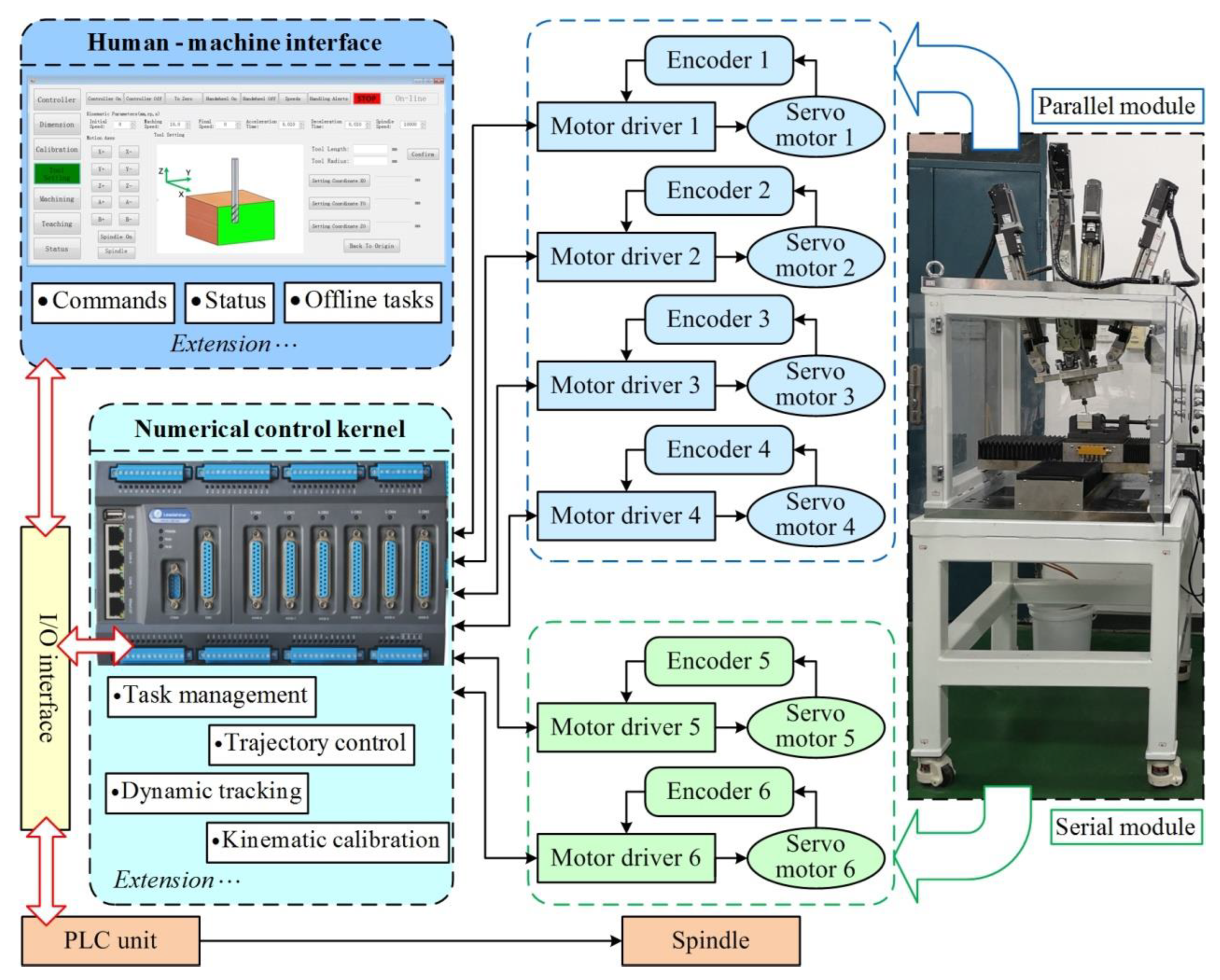
3.1. Prototype Description

Figure 3 demonstrates a fabricated prototype of the five-axis HKMU and corresponding technical specifications.
As shown in Figure 3, the five-axis HKMU consists of a mechanical frame and a CNC system. To be specific, the mechanical frame is a serial-parallel hybridized mechanism integrating a parallel module and a serial module to the base frame. Among them, the parallel module is designed as a redundantly actuated spindle head with a topology of 2UPR-2RPS. Herein, the ‘R’, ‘U’, and ‘S’ denote three types of passive joints such as revolute joint, universal joint, and spherical joint, respectively; the ‘P’ represents a prismatic actuated pair. Driven by servo motors installed on the rear end of the limbs, the platform can achieve one translational and two rotational (1T2R) motions [14]. By deploying two orthogonal sliding gantries, the serial module is designed as an auxiliary worktable to install the target workpiece. Based on these arrangements, the spindle of the HKMU can perform five-axis machining tasks along the x, y, and z axes and about the y and u axes with respect to the installed workpiece.
Meanwhile, the CNC system is in charge of status monitoring, parameter control, and human–machine information interaction. To improve multifunction and flexibility, the present CNC system is developed as an open-architecture controlling system on the basis of the C# program codes. The basic architecture of the controlling system is illustrated in Figure 4.
As shown in Figure 4, there are five components employed in the controlling system, a human–machine interface (HMI), a numerical control kernel (NCK), a programmable logic control (PLC) unit, an I/O interface, and six sets of servo motors, motor drivers and encoders. The HMI is developed to receive the user’s commands, display the operating status and execute offline tasks of the HKMU. The NCK is integrated into a motion controller, which is responsible for task management, trajectory control, dynamic tracking, and kinematic calibration of the parallel as well as the serial modules. The PLC unit is used to control the auxiliary devices, such as the spindle and the coolant/slurry tank. The developed HMI, NCK, and PLC units communicate with each other through the integrated I/O interface.
To verify the five-axis machining capacity of the exemplary HKMU, machining testing is carried out on the fabricated prototype. The testing is to machine an S-shaped workpiece from an aluminum alloy-6061 (Length × Width × High: 50 × 50 × 30 mm). Five major cutting parameters are involved, which are set as ns = 10,000 rpm, dt = 3 mm, ap = 0.4 mm, ae = 0.5 mm, and vf = 3.5 mm·s−1. Following the parameter settings, the final machined workpiece is obtained and shown in Figure 5.
As shown in Figure 5, the machined workpiece matches well with the expected S shape, in which the maximal relative error of height Hs is about 2.20% and the surface roughness Ra is less than 1.14 μm. This result clearly indicates that the prototype can fulfill a desired five-axis machining task of three translational and two rotational (3T2R)motion abilities along/about corresponding axes. However, the above cutting parameters are designated with engineering experience, limiting the machining quality and efficiency of the HKMU. To fully disclose the machining potential of the newly developed five-axis machining device, the equilibrium decision-making approach proposed in Section 2 is employed to implement appropriate decisions on the cutting parameters of the five-axis HKMU.

3.2. Design of Experiments

The experimental factors and their levels are presented in Table 1. Herein, the measures of experimental factors are carried out varying five cutting parameters such as spindle speed ns, tool diameter dt, depth of cut ap, width of cut ae, and feed rate vf in four levels. The experimental levels of the five cutting parameters are customized according to the machining unit’s technical specifications and machining capacity. In the following experiments, the aluminum alloys with dimensions of 70 mm × 70 mm × 10 mm are used as the workpieces for face milling. Experimental data is measured and arranged by using the L16(45) orthogonal factorial experiment design. The experimental combinations of the cutting parameters and corresponding levels are listed in Table 2.
To carry out the orthogonal experiments of face cutting of the exemplary HKMU, a cutting test rig is established to measure the cutting responses such as machining duration Te, cutting force Fc, and surface roughness Ra of the HKMU. The experimental setup for cutting tests is illustrated in Figure 6.
As illustrated in Figure 6, the cutting test rig mainly consists of a five-axis HKMU, a self-developed CNC system, a dynamometer (Kistler 9272, Kistler Group, Sindelfingen, German), a data acquisition system (Kistler 5167A41, Kistler Group, Sindelfingen, German), and a surface roughness tester (MarSurf PS-10, Mahr, Gottingen, German). The dynamometer is responsible for capturing the cutting signals from the testing workpiece and then transmitting the signals intothe data acquisition system to calculate the cutting force. After completing a cutting experiment, the machining duration can be obtained through the time feedback of the CNC system. Correspondingly, the roughness measurements are taken from five different sampling points using the surface roughness tester, the average of which is finally recorded as the surface roughness of a machined workpiece.
For comparability, all workpieces are machined in the same working environment except for the tested cutting parameters. In addition, there are neither significant vibrations nor regenerative chatters during the cutting process of the prototype, indicating that the experimental data is acceptable for further analysis. After experimental testing, the results are presented in Table 3.

3.3. Multi-Objectives Optimization

According to technical specifications and times of repeated cutting experiments, the design constraints of cutting parameters and the boundary conditions of optimization objectives can be determined for the HKMU. The constraints and conditions are shown in Table 4.
Based on the orthogonal experiment results in Table 3, the response surface models of the optimization objectives can be respectively constructed with commercial software of Design Expert®. To determine an appropriate surrogate model for the optimization procedure, the regression accuracy of the linear, quadratic, cubic, and quartic response surface models are assessed with the metrics of R2, RAAE, and RMAE. The assessment results are shown in Table 5 for detail.
As can be seen from Table 5, the cubic and quartic response surface models of the optimization objectives have larger values of R2 and smaller values of RAAE and RMAE, all of which imply better regression accuracy. However, the higher the order of the models, the lower the computational efficiency for the optimization is. Hence, considering the accuracy and efficiency as well, the surrogate models of machining duration [Te], cutting force [Fc], and surface roughness [Ra] are determined as the quartic, cubic, and cubic response surface models, respectively. For clarity, the polynomials of the established models are presented as Equations (17)–(19).
T e = 90,399.674 0.975 n s 14,740.776 d t 217,352 a p 143,393 a e 3599.348 v f + 4.884 n s a p + 0.651 n s a e + 32,434.890 d t a p + 26,149.613 d t a e + 550.170 d t v f + 266,240 a p a e + 215.828 a p v f + 5716.381 a e v f 56,433.104 d t a p a e 0.0629 n s d t a e v f
F c = 88.911 + 0.00537 n s + 14.257 d t + 207.944 a p + 175.492 a e 3.95 v f 5.963 e 04 n s d t 2.746 e 03 n s a p 5.576 e 03 n s a e 36.883 d t a p 18.39 d t a e + 0.493 d t v f 262.407 a p a e + 2.637 a p v f 0.892 a e v f + 51.5 d t a p a e
R a = 6.256 0.000363 n s 0.8789 d t 16.413 a p 9.696 a e + 0.263 v f + 6.969 e 06 n s d t + 5.896 e 04 n s a p + 9.64 e 05 n s a e + 2.34 d t a p + 2.23 d t a e + 2.96 e 03 d t v f + 23.972 a p a e 0.143 a p v f 0.188 a e v f 5.272 d t a p a e
By substituting the above polynomials into the multi-objective optimization model, all feasible solutions to cutting parameters can be solved. Based on this, the corresponding Pareto frontier is screened out according to the criteria in Equation (10). The feasible solutions and their Pareto frontier are illustrated in Figure 7.
As illustrated in Figure 7, there are 12,463 sets of feasible solutions available for the cutting parameters of the HKMU. By sorting the feasible solutions, the Pareto frontier is determined to fulfill the optimization with multiple objectives, in which there are 142 sets of Pareto solutions graphically located at #1 to #142 points. Clearly, the Pareto solutions fully consider the coupling relationships of multiple objectives by optimizing simultaneously. Moreover, the optimization objectives of Pareto solutions are concentrated in the ranges of [Te] [159,3534] s, [Fc] [0.0021, 22.237] N, and [Ra] [0.101, 0.644] μm, where the increase in a design objective cannot avoid a decrease in other objectives, that is, the compromised solutions on cutting parameters of the HKMU. For clarity, the Pareto solutions and corresponding cutting parameters are briefly listed in Table 6.

3.4. Correlation Analysis

Before final decision-making on cutting parameters, it is necessary to clarify the correlations between the cutting parameters and design objectives. Herein, the correlation coefficient is formulated as:
r x y = i = 1 n ( x i x ^ ) ( y i y ^ ) i = 1 n ( x i x ^ ) 2 i = 1 n ( y i y ^ ) 2
where r x y denotes the correlation coefficient between the arrays x and y; x ^ and y ^ are the averages of the arrays x and y, respectively.
The correlation coefficient is a statistic representing the closeness of two variables. To be specific, the correlation coefficient rxy is in the range of [−1, 1]. A positive rxy indicates there is a positive correlation between the two measurement variables. A negative rxy indicates there is a negative correlation between the two measurement variables. Moreover, the greater value of the correlation coefficient rxy, the stronger the correlation between the two variables, or vice versa. If the correlation coefficient rxy is equal to 0, it implies that the two variables are independent and uncorrelated with each other. For clarity, the correlation coefficients between cutting parameters and design objectives are listed in Table 7.
As can be observed from Table 7, the correlation coefficients between different cutting parameters are equal to 0, indicating that the selected parameters are independent and uncorrelated with each other; thus, the selection is reasonable. In addition, the degrees of correlations vary with design objectives and cutting parameters. To be specific, [Te] is negatively correlated with all five cutting parameters; [Fc] is negatively correlated with ns and dt, while positively correlated with ap, ae, and vf; [Ra] is negatively correlated with ns, dt, ap and ae, while only positively correlated with vf. From these investigations, the following suggestions can be put forward for cutting parameters. (1) Increasing any one of the five cutting parameters is conducive to shortening the machining duration. (2) Increasing the spindle speed and tool diameter while reducing the depth of cut, width of cut, and feed rate may obtain a smaller cutting force. (3) Increasing spindle speed, tool diameter, depth of cut, and width of cut while reducing feed rate is beneficial to improving the surface roughness of machined workpieces.
Further observations of Table 7 show that [Te] is negatively correlated with [Fc] and [Ra], while [Fc] is positively correlated with [Ra]. This reveals that machining duration is in a contradictory relationship with surface roughness while cutting force and surface roughness are in a collaborative relationship. The absolute value of the correlation coefficient between [Te] and [Fc] is 0.414, which is significantly greater than that between [Te] and [Ra] and that between [Fc] and [Ra]. This clearly indicates that the contradictory relationship between machining duration and cutting force is the dominant relationship. The above phenomenon also explains why the multiple cutting objectives cannot realize their respective best results simultaneously but reach a trade-off between themselves. Therefore, adopting the equilibrium decision-making approach we proposed would be very necessary for describing this kind of difficult decision-making.

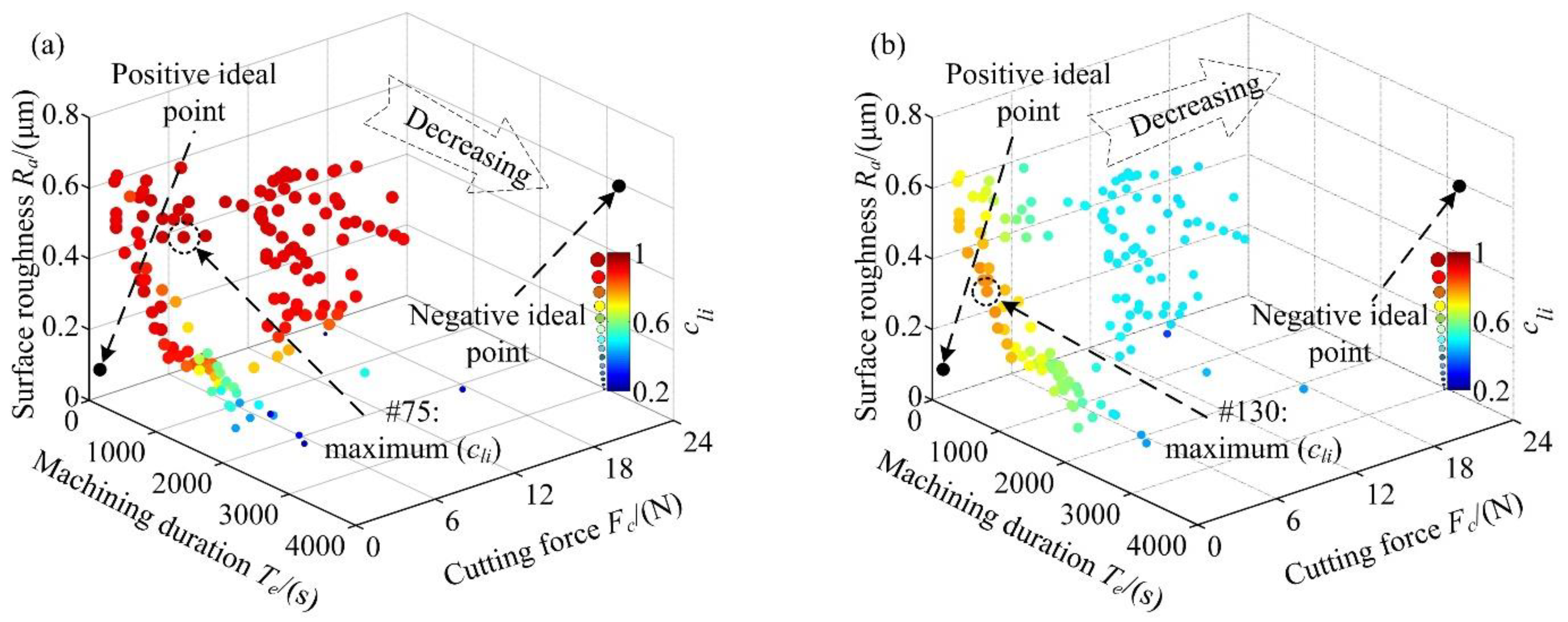
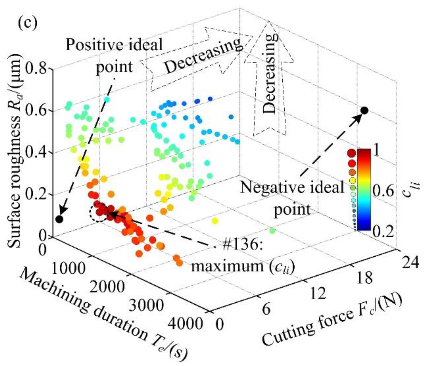
3.5. Equilibrium Decisions

Without loss of generality, three customized machining schemes with different engineering decision preferences are presented in Table 8. Herein, the decision maker’s preferences are quantized by factor wj0 (j = 1, 2, 3) with the range of 0 to 1, in which the larger the value is, the stronger the decision maker’s preferences are. Based on this, the weighting factor wj can be calculated for design objectives of [Te], [Fc], and [Ra], respectively. Three schemes are decreasing along the design objectives of [Te], [Fc], and [Fc, Ra], respectively.
Taking the three customized machining schemes as an example, the Pareto solutions are sorted to designate the best-compromised solution of the corresponding scheme. The results are illustrated in Figure 8.
As shown in Figure 8, the larger and the darker a Pareto point, the greater its corresponding relative distance index cli and the closer it is to the ideal optimum of the customized machining scheme. Further observations show that the relative distance indexes of the three schemes are decreasing along the coordinate axes of [Te], [Fc], and [Fc, Ra], respectively. Thus, the best-compromised solutions of the three customized machining schemes are designated as #75, #130, and #136 Pareto points, as illustrated in Figure 8a–c, respectively. Based on these results, the following considerations are recommended. (1) The machining tasks strictly requiring production efficiency should employ the solution locating at #75 Pareto point, i.e., ns = 12,500 rpm, dt = 6 mm, ap = 0.60 mm, ae = 65% and vf = 3.5 mm·s−1. (2) The machining tasks emphasizing the significance of machining stability should employ the solution locating at #130 Pareto point, i.e., ns = 15,000 rpm, dt = 5 mm, ap = 0.20 mm, ae = 60% and vf = 8.0 mm·s−1. (3) The machining tasks demanding both machining stability and cutting quality should employ the solution locating at #136 Pareto point, i.e., ns = 15,000 rpm, dt = 6 mm, ap = 0.20 mm, ae = 50% and vf = 5.5 mm·s−1.
For the sake of decision-making convenience, the three customized machining schemes are further compared with the scheme P0 without engineering decision preferences. The comparison results are illustrated with a radar map in Figure 9.
As illustrated in Figure 9, it can be seen that the final solutions of the three customized machining schemes have lower values on [Te], [Fc], and [Fc, Ra] than that corresponding to the scheme without engineering decision preferences, respectively. To be specific, the customized machining schemes P1, P2, and P3 reduce machining duration, cutting force, and surface roughness by 44%, 43%, and 9% compared to the scheme P0, respectively. It is coincident with the engineering decision preferences as described in Table 8. This phenomenon may also evidence that the proposed equilibrium decision-making approach makes reasonable decisions on cutting parameters of the HKMU.

4. Conclusions and Outlook

The present study proposes an equilibrium decision-making approach for cutting parameters. The application of the proposed approach is illustrated through an exemplary five-axis HKMU. The main contributions of this work can be stated as follows.
(1)
An equilibrium decision-making approach for cutting parameters of an HKMU is proposed with both multi-objective technological considerations and end users’ engineering decision preferences.
(2)
A total of 142 sets of compromised Pareto solutions and corresponding cutting parameters are determined for the typical face milling of the exemplary five-axis HKMU.
(3)
The correlation analysis reveals that machining duration is in a contradictory relationship with surface roughness while cutting force and surface roughness are in a collaborative relationship.
(4)
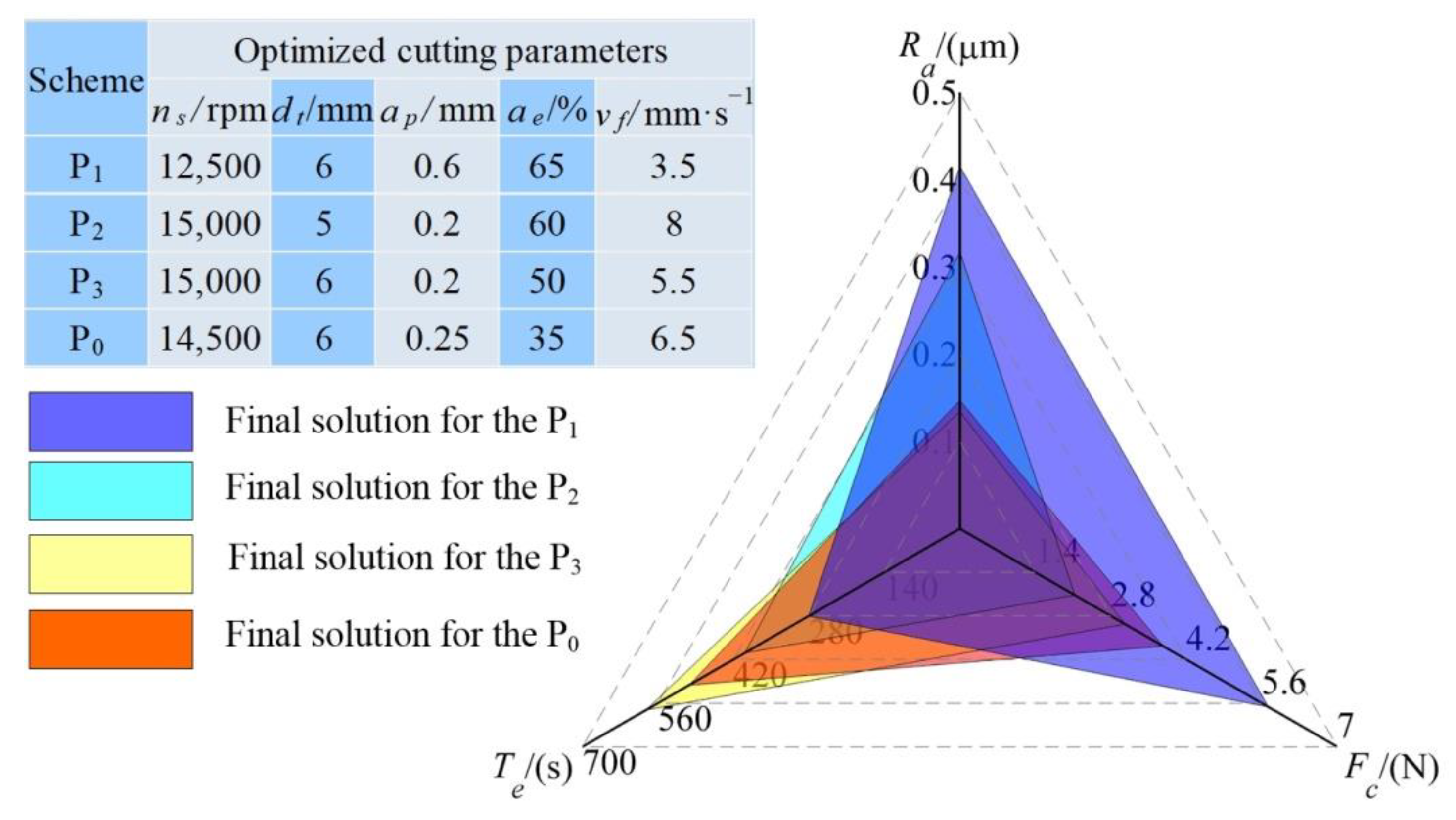
Three customized machining schemes with different engineering decision preferences are analyzed to respectively designate the best-compromised solution on cutting parameters.
(5)
Compared to the scheme without engineering decision preferences, the three schemes reduce the machining duration, the cutting force, and the surface roughness by 44%, 43%, and 9%, respectively.
The proposed approach includes both the RSM technique and surrogate model in mathematical, thus may provide an accurate yet efficient solution for cutting parameter determinations of an HKMU. In addition, this method combines the TOPSIS technique with engineering decision preferences, which enables the decision maker’s preferences to be taken into account to meet some customized requirements. Readers should note that two limitations of the proposed method are (1) the criteria weights for the customized machining schemes are subjective determinations, not based on some quantitative basis. This issue should be modified in our future study so that the method proposed can be more accurate. (2) The variable configurations of the HKMU should be taken into the design of experiments for this approach, and the related in-depth analysis will be presented elsewhere.
In the future, this proposed decision-making approach will be extended to other multi-axis machining devices with minor modifications to the design of experiments. The improvement of decision-making efficiency on cutting parameters, such as visually integrating the proposed approach into the self-developed CNC system, will be carried out in our next work.

Author Contributions

Conceptualization, T.T. and J.Z.; methodology, T.T.; software, W.T.; validation, T.T., W.T. and H.L.; formal analysis, T.T.; investigation, T.T.; resources, W.T.; data curation, H.L.; writing—original draft preparation, T.T.; writing—review and editing, T.T.; visualization, T.T.; supervision, J.Z.; project administration, J.Z.; funding acquisition, J.Z. All authors have read and agreed to the published version of the manuscript.

Funding

This work was supported by the Open Fund of the State Key Laboratory for Mechanical Transmissions, Chongqing University (Grant number SKLMT-ZDKFKT-202003), the Natural Science Foundation for Distinguished Young Scholar of Fujian Province (Grant number 2020J06010), and the Industry-Academy Cooperation Project of Fujian Province (Grant number 2019H6006). The corresponding author is also thankful to the sponsor of the National Natural Science Foundation of China (Grant number 51875105).

Institutional Review Board Statement

Not applicable.

Informed Consent Statement

Not applicable.

Data Availability Statement

Not applicable.

Conflicts of Interest

The authors declare no conflict of interest.

References

  1. Uriarte, L.; Zatarain, M.; Axinte, D.; Yagüe-Fabra, J.; Ihlenfeldt, S.; Eguia, J.; Olarra, A. Machine tools for large parts. CIRP Ann. 2013, 62, 731–750. [Google Scholar] [CrossRef]
  2. Zhao, H.; Yu, X.; Li, X.; Ding, H. Weighted sum of vector norms based contouring control method for five-axis CNC machine tools. Precis. Eng. 2019, 60, 93–103. [Google Scholar] [CrossRef]
  3. Laryushkin, P.; Antonov, A.; Fomin, A.; Essomba, T. Velocity and Singularity Analysis of a 5-DOF (3T2R) Parallel-Serial (Hybrid) Manipulator. Machines 2022, 10, 276. [Google Scholar] [CrossRef]
  4. Zhao, Y.; Mei, J.; Jin, Y.; Niu, W. A new hierarchical approach for the optimal design of a 5-dof hybrid serial-parallel kinematic machine. Mech. Mach. Theory 2020, 156, 104160. [Google Scholar] [CrossRef]
  5. Lai, Y.-L.; Liao, C.-C.; Chao, Z.-G. Inverse kinematics for a novel hybrid parallel–serial five-axis machine tool. Robot. Comput. Manuf. 2018, 50, 63–79. [Google Scholar] [CrossRef]
  6. Qin, X.; Shi, M.; Hou, Z.; Li, S.; Li, H.; Liu, H. Analysis of 3-DOF Cutting Stability of Titanium Alloy Helical Milling Based on PKM and Machining Quality Optimization. Machines 2022, 10, 404. [Google Scholar] [CrossRef]
  7. Xu, P.; Cheung, C.; Wang, C.; Zhao, C. Novel hybrid robot and its processes for precision polishing of freeform surfaces. Precis. Eng. 2020, 64, 53–62. [Google Scholar] [CrossRef]
  8. Li, Q.; Wu, W.; Xiang, J.; Li, H.; Wu, C. A hybrid robot for friction stir welding. Proc. Inst. Mech. Eng. Part C J. Mech. Eng. Sci. 2014, 229, 2639–2650. [Google Scholar] [CrossRef]
  9. Oba, Y.; Kakinuma, Y. Simultaneous tool posture and polishing force control of unknown curved surface using serial-parallel mechanism polishing machine. Precis. Eng. 2017, 49, 24–32. [Google Scholar] [CrossRef]
  10. Zhang, D.; Xu, Y.; Yao, J.; Zhao, Y. Design of a novel 5-DOF hybrid serial-parallel manipulator and theoretical analysis of its parallel part. Robot. Comput. Manuf. 2018, 53, 228–239. [Google Scholar] [CrossRef]
  11. Olazagoitia, J.L.; Wyatt, S. New PKM Tricept T9000 and Its Application to Flexible Manufacturing at Aerospace Industry; SAE Technical Paper 07ATC-94; SAE: Warrendale, PA, USA, 2007. [Google Scholar] [CrossRef]
  12. Hennes, N. Ecospeed—An innovative machinery concept for high performance 5 axis machining of large structural components in aircraft engineering. In Proceedings of the 3rd Chemnitz Parallel Kinematics Seminar, Chemnitz, Germany, 23–25 April 2002; pp. 763–774. [Google Scholar]
  13. Bi, Z.M. Kinetostatic modeling of Exechon parallel kinematic machine for stiffness analysis. Int. J. Adv. Manuf. Technol. 2014, 71, 325–335. [Google Scholar] [CrossRef]
  14. Jiang, S.; Chi, C.; Fang, H.; Tang, T.; Zhang, J. A minimal-error-model based two-step kinematic calibration methodology for redundantly actuated parallel manipulators: An application to a 3-DOF spindle head. Mech. Mach. Theory 2021, 167, 104532. [Google Scholar] [CrossRef]
  15. Tang, T.; Fang, H.; Zhang, J. Hierarchical design, laboratory prototype fabrication and machining tests of a novel 5-axis hybrid serial-parallel kinematic machine tool. Robot. Comput. Manuf. 2020, 64, 101944. [Google Scholar] [CrossRef]
  16. Fang, H.; Tang, T.; Zhang, J. Kinematic analysis and comparison of a 2R1T redundantly actuated parallel manipulator and its non-redundantly actuated forms. Mech. Mach. Theory 2019, 142, 103587. [Google Scholar] [CrossRef]
  17. Xu, X. Machine Tool 4.0 for the new era of manufacturing. Int. J. Adv. Manuf. Technol. 2017, 92, 1893–1900. [Google Scholar] [CrossRef]
  18. Calleja, A.; Bo, P.; González, H.; Bartoň, M.; de Lacalle, L.N.L. Highly accurate 5-axis flank CNC machining with conical tools. Int. J. Adv. Manuf. Technol. 2018, 97, 1605–1615. [Google Scholar] [CrossRef]
  19. Srivastava, V.S.; Gupta, T.K.; Srivastava, A.K.; Chauhan, S.; Chauhan, P.K. Effects of cutting parameters on aluminium alloys-A review. Mater. Today Proc. 2021, 47, 3823–3827. [Google Scholar] [CrossRef]
  20. Wang, S.; Zhou, Y.; Tang, J.; Tang, K.; Li, Z. Digital tooth contact analysis of face gear drives with an accurate measurement model of face gear tooth surface inspected by CMMs. Mech. Mach. Theory 2022, 167, 104498. [Google Scholar] [CrossRef]
  21. Zhou, Y.-S.; Tang, Z.-W.; Shi, X.-L.; Tang, J.-Y.; Li, Z.-M. Efficient and accurate worm grinding of spur face gears according to an advanced geometrical analysis and a closed-loop manufacturing process. J. Central South Univ. 2022, 29, 1–13. [Google Scholar] [CrossRef]
  22. Ghosh, G.; Mandal, P.; Mondal, S.C. Modeling and optimization of surface roughness in keyway milling using ANN, genetic algorithm, and particle swarm optimization. Int. J. Adv. Manuf. Technol. 2019, 100, 1223–1242. [Google Scholar] [CrossRef]
  23. Meral, G.; Sarıkaya, M.; Mia, M.; Dilipak, H.; Şeker, U.; Gupta, M.K. Multi-objective optimization of surface roughness, thrust force, and torque produced by novel drill geometries using Taguchi-based GRA. Int. J. Adv. Manuf. Technol. 2018, 101, 1595–1610. [Google Scholar] [CrossRef]
  24. Zhang, L.; Zhang, B.; Bao, H.; Huang, H. Optimization of Cutting Parameters for Minimizing Environmental Impact: Considering Energy Efficiency, Noise Emission and Economic Dimension. Int. J. Precis. Eng. Manuf. 2018, 19, 613–624. [Google Scholar] [CrossRef]
  25. Sofuoğlu, M.A.; Arapoğlu, R.A.; Orak, S. Multi objective optimization of turning operation using hybrid decision making analysis. Anadolu Univ. J. Sci. Technol. Appl. Sci. Eng. 2017, 18, 595–610. [Google Scholar] [CrossRef]
  26. Sofuoglu, A. A Novel Hybrid Multi Criteria Decision Making Model: Application to Turning Operations. Int. J. Intell. Syst. Appl. Eng. 2017, 5, 124–131. [Google Scholar] [CrossRef]
  27. Utsumi, K.; Shichiri, S.; Sasahara, H. Determining the effect of tool posture on cutting force in a turn milling process using an analytical prediction model. Int. J. Mach. Tools Manuf. 2020, 150, 103511. [Google Scholar] [CrossRef]
  28. Guo, Q.; Zhao, B.; Jiang, Y.; Zhao, W. Cutting force modeling for non-uniform helix tools based on compensated chip thickness in five-axis flank milling process. Precis. Eng. 2018, 51, 659–681. [Google Scholar] [CrossRef]
  29. Zerti, A.; Yallese, M.A.; Meddour, I.; Belhadi, S.; Haddad, A.; Mabrouki, T. Modeling and multi-objective optimization for minimizing surface roughness, cutting force, and power, and maximizing productivity for tempered stainless steel AISI 420 in turning operations. Int. J. Adv. Manuf. Technol. 2018, 102, 135–157. [Google Scholar] [CrossRef]
  30. Balaji, M.; Rao, K.V.; Rao, N.M.; Murthy, B. Optimization of drilling parameters for drilling of TI-6Al-4V based on surface roughness, flank wear and drill vibration. Measurement 2018, 114, 332–339. [Google Scholar] [CrossRef]
  31. He, C.L.; Zong, W.J.; Zhang, J.J. Influencing factors and theoretical modeling methods of surface roughness in turning process: State-of-the-art. Int. J. Mach. Tools Manuf. 2018, 129, 15–26. [Google Scholar] [CrossRef]
  32. Zerti, A.; Yallese, M.A.; Zerti, O.; Nouioua, M.; Khettabi, R. Prediction of machining performance using RSM and ANN models in hard turning of martensitic stainless steel AISI 420. Proc. Inst. Mech. Eng. Part C J. Mech. Eng. Sci. 2019, 233, 4439–4462. [Google Scholar] [CrossRef]
  33. Li, C.; Xiao, Q.; Tang, Y.; Li, L. A method integrating Taguchi, RSM and MOPSO to CNC machining parameters optimization for energy saving. J. Clean. Prod. 2016, 135, 263–275. [Google Scholar] [CrossRef]
  34. Li, B.; Tian, X.; Zhang, M. Modeling and multi-objective optimization of cutting parameters in the high-speed milling using RSM and improved TLBO algorithm. Int. J. Adv. Manuf. Technol. 2020, 111, 2323–2335. [Google Scholar] [CrossRef]
  35. Yan, J.; Li, L. Multi-objective optimization of milling parameters—The trade-offs between energy, production rate and cutting quality. J. Clean. Prod. 2013, 52, 462–471. [Google Scholar] [CrossRef]
  36. Li, L.; Deng, X.; Zhao, J.; Zhao, F.; Sutherland, J. Multi-objective optimization of tool path considering efficiency, energy-saving and carbon-emission for free-form surface milling. J. Clean. Prod. 2018, 172, 3311–3322. [Google Scholar] [CrossRef]
  37. De Oliveira, L.G.; de Oliveira, C.H.; de Brito, T.G.; de Paiva, E.J.; de Paiva, A.P.; Ferreira, J.R. Nonlinear optimization strategy based on multivariate prediction capability ratios: Analytical schemes and model validation for duplex stainless steel end milling. Precis. Eng. 2020, 66, 229–254. [Google Scholar] [CrossRef]
  38. Zhang, C.; Li, W.; Jiang, P.; Gu, P. Experimental investigation and multi-objective optimization approach for low-carbon milling operation of aluminum. Proc. Inst. Mech. Eng. Part C J. Mech. Eng. Sci. 2017, 231, 2753–2772. [Google Scholar] [CrossRef]
  39. De Oliveira, L.G.; de Paiva, A.P.; Campos, P.H.D.S.; de Paiva, E.J.; Balestrassi, P.P. Prediction capability of Pareto optimal solutions: A multi-criteria optimization strategy based on model capability ratios. Precis. Eng. 2019, 59, 185–210. [Google Scholar] [CrossRef]
  40. Kumar, R.; Bilga, P.S.; Singh, S. Multi objective optimization using different methods of assigning weights to energy consumption responses, surface roughness and material removal rate during rough turning operation. J. Clean. Prod. 2017, 164, 45–57. [Google Scholar] [CrossRef]
  41. Jiang, Z.; Gao, D.; Lu, Y.; Liu, X. Optimization of Cutting Parameters for Trade-off Among Carbon Emissions, Surface Roughness, and Processing Time. Chin. J. Mech. Eng. 2019, 32, 1–18. [Google Scholar] [CrossRef] [Green Version]
  42. Kubler, S.; Robert, J.; Derigent, W.; Voisin, A.; Le Traon, Y. A state-of the-art survey & testbed of fuzzy AHP (FAHP) applications. Expert Syst. Appl. 2016, 65, 398–422. [Google Scholar] [CrossRef]
  43. Behzadian, M.; Otaghsara, S.K.; Yazdani, M.; Ignatius, J. A state-of the-art survey of TOPSIS applications. Expert Syst. Appl. 2012, 39, 13051–13069. [Google Scholar] [CrossRef]
  44. Teti, R.; Mourtzis, D.; D’Addona, D.; Caggiano, A. Process monitoring of machining. CIRP Ann. 2022, 71, 529–552. [Google Scholar] [CrossRef]
Figure 1. Framework of the equilibrium decision-making approach.
Machines 10 00824 g001
Figure 2. Flowchart of the equilibrium decision-making approach.
Machines 10 00824 g002
Figure 3. A full-scale prototype of the five-axis HKMU.
Machines 10 00824 g003
Figure 4. Basic architecture of the developed controlling system.
Machines 10 00824 g004
Figure 5. Five-axis machining of the S-shaped workpiece.
Machines 10 00824 g005
Figure 6. Experimental setup for cutting tests for the five-axis HKMU.
Machines 10 00824 g006
Figure 7. Feasible solutions and their Pareto frontier.
Machines 10 00824 g007
Figure 8. Sorted Pareto solutions of the three customized machining schemes: (a) P1, (b) P2, (c) P3.
Machines 10 00824 g008aMachines 10 00824 g008b
Figure 9. Radar map of the final solutions of the four machining schemes.
Machines 10 00824 g009
Table 1. Experimental factors and their levels.
FactorsLevels
1234
A: Spindle speed ns/rpm900011,00013,00015,000
B: Tool radius dt/mm3456
C: Depth of cut ap/mm0.150.300.450.60
D: Width of cut ae/%20406080
E: Feed rate vf/mm·s−12468
Table 2. Orthogonal factorial experiment design: L16(45).
Exp. No.Spindle Speed
ns/rpm
Tool Radius
dt/mm
Depth of Cut
ap/mm
Width of Cut
ae/%
Feed Rate
vf/mm·s−1
1900030.1520 (0.6 mm)2
2900040.3040 (1.6 mm)4
3900050.4560 (3.0 mm)6
4900060.6080 (4.8 mm)8
511,00030.3060 (1.8 mm)8
611,00040.1580 (3.2 mm)6
711,00050.6020 (1.0 mm)4
811,00060.4540 (2.4 mm)2
913,00030.4580 (2.4 mm)4
1013,00040.6060 (2.4 mm)2
1113,00050.1540 (2.0 mm)8
1213,00060.3020 (1.2 mm)6
1315,00030.6040 (1.2 mm)6
1415,00040.4520 (0.8 mm)8
1515,00050.3080 (4.0 mm)2
1615,00060.1560 (3.6 mm)4
Table 3. Experimental results of the face milling of the HKMU.
Exp. No.Machining Duration
Te/s
Cutting Force
Fc/N
Surface Roughness
Ra/μm
114,8563.2780.172
2144013.4750.213
338017.0610.532
415923.3150.180
573811.6610.219
6114017.4510.168
710208.2040.149
812646.3680.104
980419.6010.162
10107117.2850.231
1113204.2030.430
1211284.3120.126
1368422.5850.160
1488812.4100.298
1514048.8800.102
1614283.9580.118
Table 4. Design constraints and boundary conditions.
ValueMinimum/
Upper Bound
Maximum/
Lower Bound
ValueMinimum/
Upper Bound
Maximum/
Lower Bound
ns/rpm900015,000dt/mm36
ap/mm0.150.60ae/%2080
vf/mm·s−128Te/s15914,856
Fc/N0.1224Ra/μm0.1013.2
Table 5. Accuracy assessment for the response surface models.
Assessment metricsR2RAAERMAE
Machining duration
Te/s
Linear0.65720.5051192841.7662867
Quadratic0.96360.0869002170.5213963
Cubic10.0001705380.000244
Quartic10.00005030.000108
Cutting force
Fc/N
Linear0.85710.3100678580.9704946
Quadratic0.99390.0352632840.2109161
Cubic10.000118670.0013264
Quartic10.0001178090.0013162
Surface roughness
Ra/μm
Linear0.27271.2130013754.4719211
Quadratic0.78790.235237711.3923391
Cubic10.003085980.0188888
Quartic10.0030555390.0191743
Table 6. Pareto solutions and corresponding cutting parameters.
Point
No.
Pareto SolutionsCutting Parameters
Te/sFc/NRa/μmns/rpmdt/mmap/mmae/%vf/mm·s−1
#116140.8120.266900060.55203.00
#219717.4600.450900060.55656.50
#5032612.6370.41011,50050.5565.00
#5197410.1690.10311,50050.60353.00
#1002692.7070.51113,75060.60753.50
#10140718.0990.10614,00030.50456.50
#1413632.0250.34715,00060.25407.50
#1427531.7150.35815,00060.25457.00
Table 7. Correlation coefficients between cutting parameters and design objectives.
Correlation
Coefficients
nsdtapaevfTeFcRa
ns10000−0.307−0.111−0.230
dt01000−0.329−0.337−0.063
ap00100−0.4040.611−0.017
ae00010−0.3660.534−0.049
vf00001−0.3960.2680.461
Te−0.307−0.329−0.404−0.366−0.3961−0.414−0.120
Fc−0.111−0.3370.6110.5340.268−0.41410.123
Ra−0.230−0.063−0.017−0.0490.461−0.1200.1231
Table 8. Three customized machining schemes with engineering decision preferences.
SchemesDecision Maker’s PreferencesWeighting FactorsEngineering Decision Preferences
w10
(Te)
w20
(Fc)
w30
(Ra)
w j = w j 0 / j = 1 3 w j 0
P10.50.10.1[0.714:0.143:0.143][Te]
P20.10.50.1[0.143:0.714:0.143][Fc]
P30.10.50.5[0.091:0.454:0.454][Fc, Ra]
Publisher’s Note: MDPI stays neutral with regard to jurisdictional claims in published maps and institutional affiliations.

