Article

Multi-Physics Comparison of Surface-Mounted and Interior Permanent Magnet Synchronous Motor for High-Speed Applications

School of Electrical and Control Engineering, Xi’an University of Science and Technology, Xi’an 710054, China
*
Author to whom correspondence should be addressed.
Machines 2022, 10(8), 700; https://doi.org/10.3390/machines10080700
Submission received: 23 July 2022 / Revised: 10 August 2022 / Accepted: 16 August 2022 / Published: 17 August 2022
(This article belongs to the Special Issue Advances and Trends in PM-Free or Rare-Earth-Free PM Motors)

Abstract

:
For high-speed permanent magnet machines (HSPMMs), two different rotor structures are widely used: surface-mounted permanent magnet (SPM) and interior permanent magnet (IPM). The two different rotor structures have a large impact on the comprehensive performance in multiple physical fields of HSPMMs, including mechanical stress, electromagnetic characteristics, and temperature distribution. However, the multi-physics comparison of two different rotor structures is rare in the existing literature, which makes it difficult for designers to choose a suitable rotor structure. Therefore, in this paper, the comprehensive performance of multi-physics for SPM and IPM is comprehensively compared and analyzed. Firstly, the SPM and IPM were designed under 60 kW and 30,000 rpm with the condition of the same stator structure, winding type and volume. Secondly, to ensure that the two rotor structures meet the stress-field constraints, a finite element model (FEM) was built in Ansys Workbench. The influence of different parameters on the rotor stress was analyzed. Following this, the electromagnetic characteristics and temperature distributions of the two motors were compared and analyzed comprehensively through the FEM. Finally, a prototype of an SPM rotor structure is selected and manufactured. The validity of the multi-physics analysis and design was verified through experimental measurements. The above analysis will provide a reference when a designer chooses a rotor structure for an HSPMM.

1. Introduction

In recent years, with the rapid development of high-frequency drive power and high-performance PM materials, high-speed permanent magnet machines (HSPMMs) have been widely studied [1,2]. Because of the demand for higher power density and efficiency, HSPMMs are becoming increasingly popular in various fields, such as distributed power generation systems, flywheel energy storage and compressors [3]. HSPMMs have two different rotor structures: a surface-mounted permanent magnet (SPM) and an interior permanent magnet (IPM) [4,5,6]. The PM materials have high compressive strength and low tensile strength. The PM of an SPM motor needs to set a high-strength protective sleeve outside the PM [7]. The PM of an IPM motor is embedded in the rotor core, so the structure is more complicated than the SPM. At high speed, the centrifugal force is mainly concentrated on the magnetic bridge, which easily causes damage to the magnetic bridge. This structure has a conflict between rotor flux leakage and rotor safety [8]. Both SPM and IPM motors have their own advantages and disadvantages, but the multi-physics comparison of two different rotor structures, which will be the focus of this paper, is not yet clear.
In the existing literature, there are many papers that compare and analyze the performance of a certain rotor structure, but only a few studies focus on comparing the comprehensive performance of two rotor structures. For the SPM rotor structure, the tangential stress of the PM can be effectively reduced with the tangential segmentation of the PM. For applications requiring high power density, alloy protective sleeves cannot meet the constraints of multi-physics due to large eddy-current losses [9,10]. The electrical conductivity of the sleeve has a great influence on the eddy-current distribution in the rotor of the HSPMM [11]. The greater the thickness of the sleeve, the smaller the equivalent stress of the sleeve will be. However, this also increases the difficulty of heat dissipation due to the poor heat dissipation capability of the sleeve [12]. In the case of the outer diameter of the rotor being the same, the thickness of the carbon-fiber sleeve can be smaller than that of the alloy sleeve. Under the condition of the same power density, the PM usage of the ring PM motor is less than that of the cylinder PM motor [13]. The electromagnetic characteristics of the two different IPM rotor structures are mainly compared, including double-layer PM rotor structures and single-layer PM rotor structures. The electromagnetic performance of the double-layer PM rotor structures is better compared to the single-layer PM [14]. Three kinds of different IPM rotor structures are compared, including the single-V shape, double-V shape and delta shape. Through analysis, it is concluded that the overall performance of the single-V type is the best [15]. For an 8-kW, 40,000-rpm HSPMM, the loss distribution of a new type of IPM and SPM rotor structure is compared, in terms of motor efficiency, stator copper loss and rotor iron loss [16]. For a 140-kW, 24,000-rpm HSPMM, spoke-type IPM and SPM rotor structures are designed, and the mechanical, electromagnetic and thermal performances are compared [17]. For an 11-kW, 8200-rpm motor, the loss characteristics and temperature distributions of SPM and tangential IPM are compared. The comparative analysis shows that the total loss of the IPM rotor structure is higher than that of the SPM, but the performance of the IPM rotor structure is better than that of the SPM [18]. From the above literature analysis, it can be seen that both SPM rotor structures and IPM rotor structures have been studied. The PM of an SPM motor needs to be set with a high-strength protective sleeve, which will lead to poor heat dissipation. The IPM rotor structure not only avoids the poor thermal conductivity of the sleeve, but also has good heat dissipation performance in the rotor core. However, the rotor stress constraints of the IPM rotor structure are difficult to satisfy. Therefore, both SPM and IPM rotor structures have different advantages and disadvantages in multiple physical fields, including rotor stress, electromagnetic fields, and temperature fields. However, the comparison of the two rotor structures in the existing literature is only based on a single physical field, and it would be difficult for the designer to fully judge which rotor structure is more suitable. Therefore, the SPM and IPM rotor structures are compared and analyzed based on multiple physical fields.
In this paper, the comprehensive performances of two rotor structures are discussed and comparatively investigated in multiple physical fields, including rotor stress, electromagnetic characteristics, losses and temperature distribution. In Section 2, the SPM motor with a carbon-fiber protective sleeve and the IPM motor with a radial structure are selected. The initial electromagnetic design schemes for two different rotor structures are presented. In Section 3, the 2D-FEM is established in Ansys Workbench. Stress analysis of the two different rotor structures is carried out. In Section 4, the 2D-FEM is established in Ansys Maxwell. The electromagnetic performances of the two motors are calculated and compared—for example, their magnetic flux density, electromotive motor force and loss. In Section 5, the 2D-FEM is established in Motor-CAD. The cooling system is designed. The temperature distributions of the two rotor structures are compared. In Section 6, a prototype is manufactured based on the SPM rotor structure, then the electromagnetic characteristics, thermal distribution and operating conditions are experimentally measured. The validity of the multi-physics analysis and design is verified. In Section 7, the comprehensive performances of multiple physical fields of the two rotor structures are regularly summarized, and three conclusions are drawn, including mechanical stress, electromagnetic characteristics and temperature characteristics. In the future, the results of multi-physics comparisons have a certain reference value for selecting between the two rotor structures when designing an HSPMM.

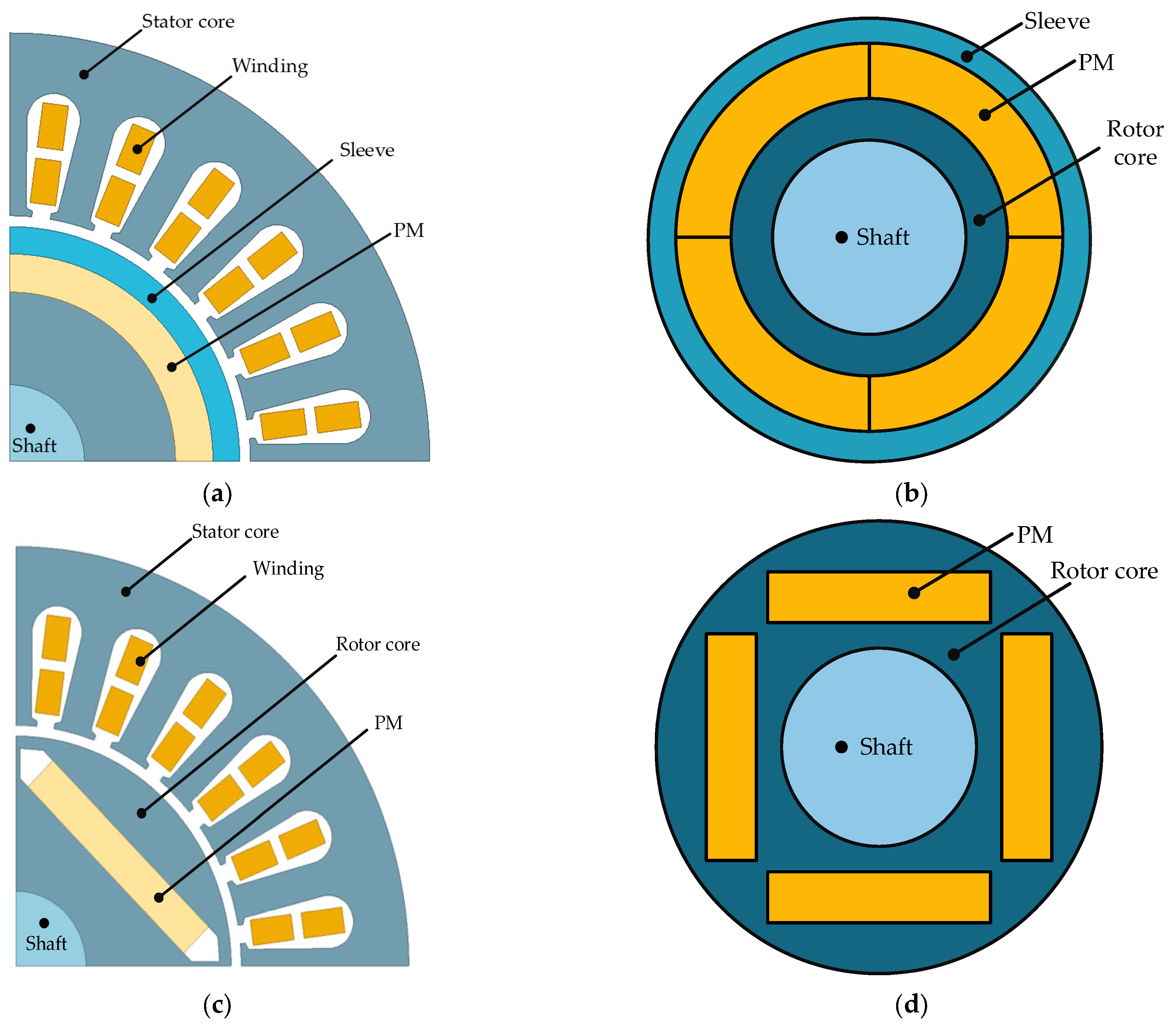
2. Motor Structure and Parameters

In this paper, two different motor structures are designed for a 60-kW, 30,000-rpm HSPMM. As shown in Figure 1, a 24-slot and 4-pole HSPMM was designed. N38UH PM material was selected because of its high remanence and relatively larger coercive force. The main parameters of two motors are listed in Table 1. The key parameter sizes remained the same when designing the two motors.
The models of the SPM motor are shown in Figure 1a,b. The structure of the SPM motor is simple, since the PM is attached to the surface of the rotor core. However, the tensile strength of PM is low. It is necessary to set a carbon-fiber protective sleeve on the external surface of PM to protect the PM.
The models of the IPM motor are shown in Figure 1c,d. The PM of the IPM motor is embedded in the rotor core, so the structure is more complicated than the SPM motor. However, the IPM rotor structure saves a protective sleeve, and the heat dissipation performance is better than that of the SPM.
Multi-physics constraints, such as rotor stress, electromagnetic characteristics and temperature distribution, should be satisfied during the design of the HSPMM. In this motor design process, the main physics field constraints considered are as follows:
  • Stress-field constraints: The maximum yield strength of PM is 75 MPa. The sleeve strength yield limit is 1960 MPa. The yield strength of the rotor core is 480 MPa.
  • Electromagnetic field constraints: The output power in the rated load is 60 kW. In the design, a commercial frequency converter is used, which can output a peak voltage of 600 V. Considering the voltage margin of the converter, the amplitude of the back-EMF under no load is limited between 500 V and 540 V. The amplitude of air-gap magnetic flux density is between 0.4 T and 0.6 T. The thermal load is required to be < 200   A 2 / mm 3 .
  • Thermal field constraints: The limited working temperature of PM materials is 150 °C. The maximum temperature of the rotor is 150 °C. The maximum winding temperature is 130 °C.

3. Rotor Stress Analysis

In the design process of an HSPMM, a reasonable rotor stress analysis is a necessary prerequisite to guarantee its safety and reliability. In this Section, in order to comparatively analyze the stress field of the two kinds of rotor structures, 2D-FEM is established. According to symmetry, a 1/4 cross-sectional model of the HSPMM is used in Ansys Workbench.
Based on the material properties presented in Table 2, the stress distribution characteristics of rotors with different rotor structures are calculated [19,20]. In the stress simulation, the simulated operating states of the motors with two rotor structures are that the motors run at high speed and the rotors are in a high-temperature thermal environment. That is, the motor speed is 30,000 rpm and the temperature rise of each part of the rotor is 100 °C. For the SPM motor, the maximum tangential stress of PM, the maximum equivalent stress of sleeve and the total deformation of sleeve and PM are simulated, respectively. For the IPM motor, the maximum equivalent stress and total deformation of the rotor are calculated.

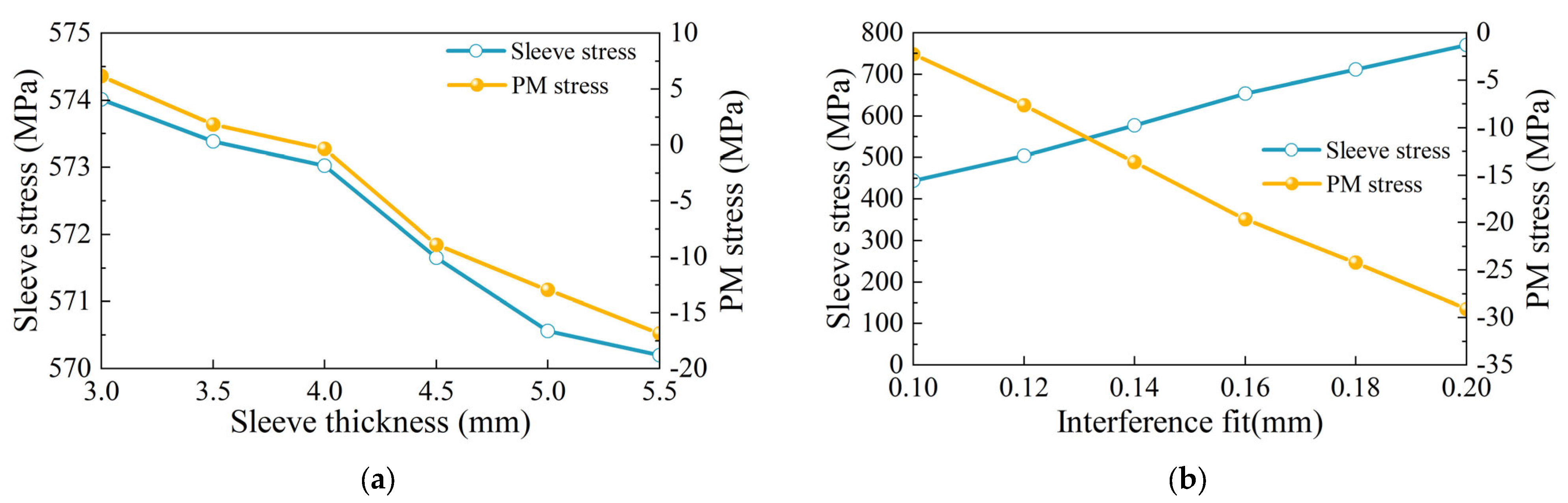
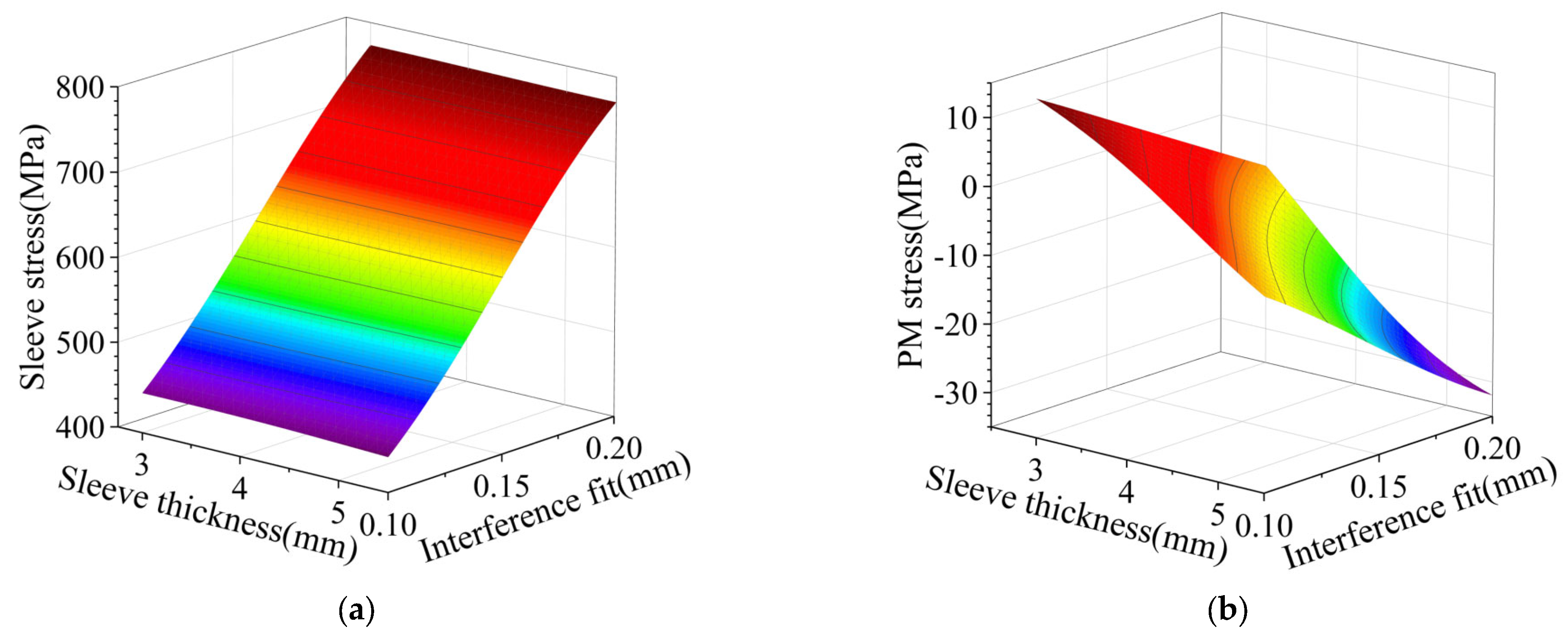
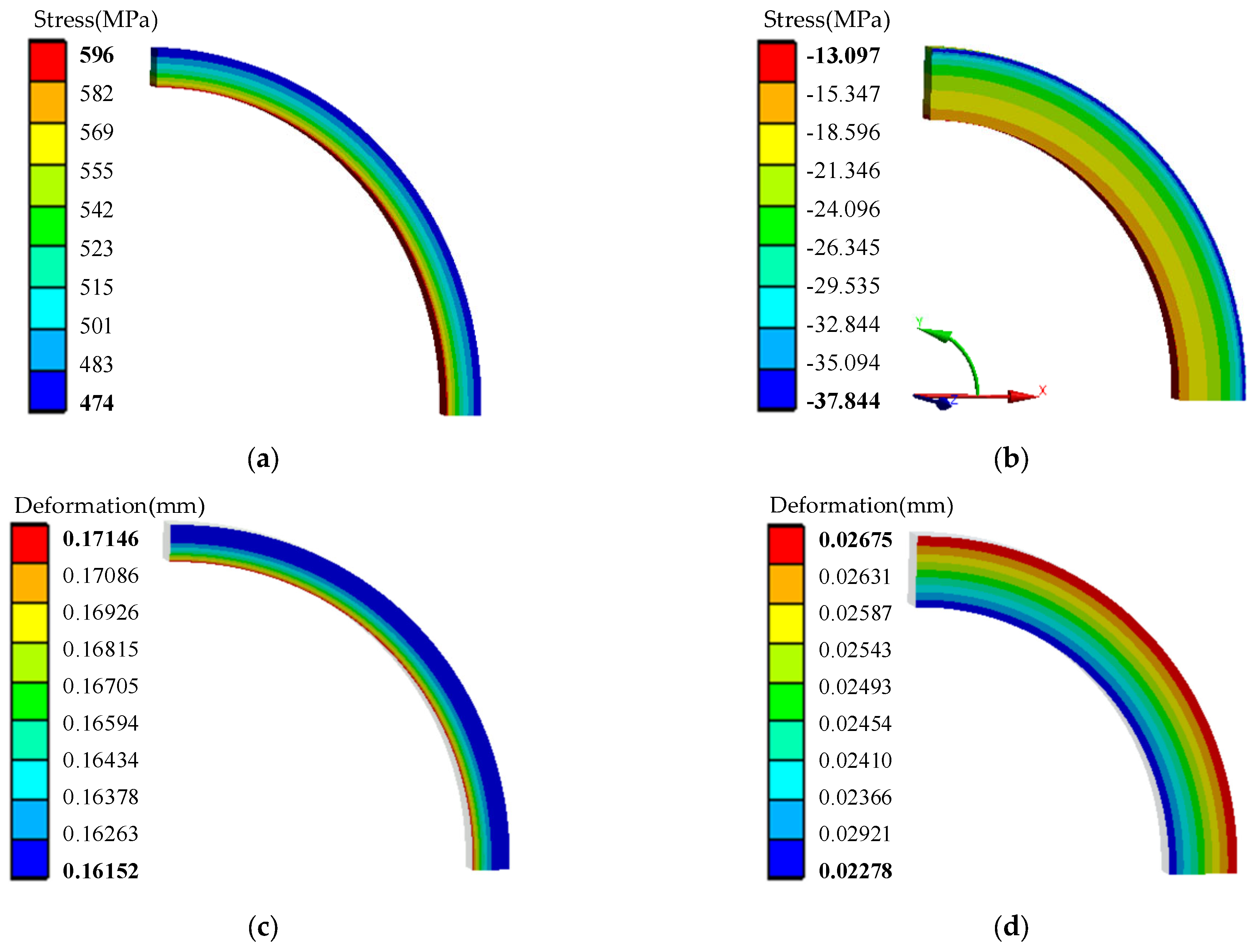
3.1. Stress Analysis of SPM Rotor

NdFeB PM materials have high compressive strength and low tensile strength. Therefore, it is necessary to set a protective sleeve outside the PM, and use an interference fit to impose compressive stress on the PM. Too thick a sleeve can result in a large effective air-gap length (including air gap length and sleeve thickness). The electromagnetic performance of the motor is affected. If the sleeve is too thin, the sleeve may loosen and deform. Too much interference fit can make installation difficult and even damage the contact surfaces. Too little interference fit may loosen the sleeve. Therefore, a reasonable selection of sleeve thickness and interference fit is important for HSPMMs with SPM rotor structures. The SPM motor stress analysis is simulated by building 2D-FEM. The carbon fiber sleeve is mounted on the PM outer surface by interference fit
Keeping the same interference fit, the influence of sleeve thicknesses on the stress of sleeve and PM is shown in Figure 2a. It can be seen that the PM stress decreases with the increase in the sleeve thickness. The equivalent stress of the sleeve also decreases gradually as the sleeve thickness increases, but when the sleeve thickness is more than 5 mm, the decreasing trend of sleeve stress becomes slow. This means that the continuous increase in the sleeve thickness does not significantly reduce the sleeve stress. Combined with the above analysis, the sleeve thickness selected is 5 mm.
Keeping the sleeve thickness constant, the influence of interference fit on the sleeve and PM stress is shown in Figure 2b. As the interference fit increases, the stress of the sleeve increases, but the stress of the PM decreases. When the interference fit is 0.2 mm, the sleeve stress is 770 MPa and PM stress is −30 MPa. The maximum tangential stress of the PM is negative, which means that it is subjected to compressive stress. The interference fit is selected as 0.15 mm within the stress-field constraint.
The effects of sleeve thickness and interference fit on sleeve stress and PM stress are shown in Figure 3. It can be seen from Figure 3a that the equivalent stress of the sleeve decreases as the sleeve thickness increases and the interference fit decreases. The variation in sleeve stress with interference fit is severe, which means that the effect of interference fit on sleeve stress is more obvious compared to the sleeve thickness. The sleeve thickness has little effect on the sleeve stress by comparison. The influences of sleeve thickness and interference fit on the PM stress are shown in Figure 3b. The sleeve thickness and the interference fit both have a great influence on the tangential stress of the PM.
Combining the results in Figure 2 and Figure 3, the sleeve thickness and interference fit are selected to be 5 mm and 0.15 mm, respectively. The stress simulation results are shown in Figure 4. The maximum tangential stress of PM is −13 MPa. The equivalent stress of the sleeve is 596 MPa. The deformations of the sleeve and PM are 0.17 mm and 0.03 mm, respectively. It is clear that the stresses of the sleeve and the PM both satisfy the stress-field constraints with a large margin.

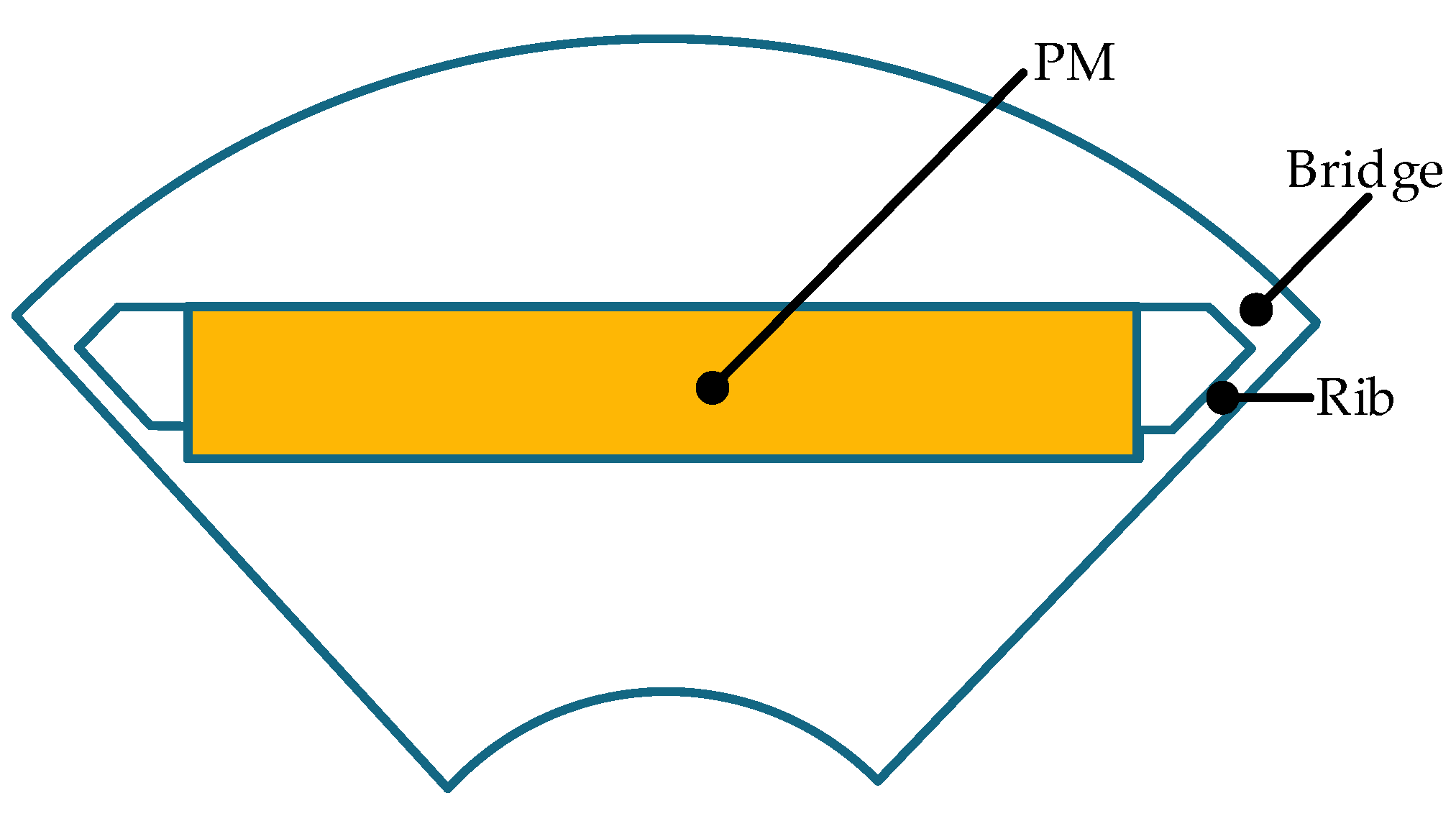
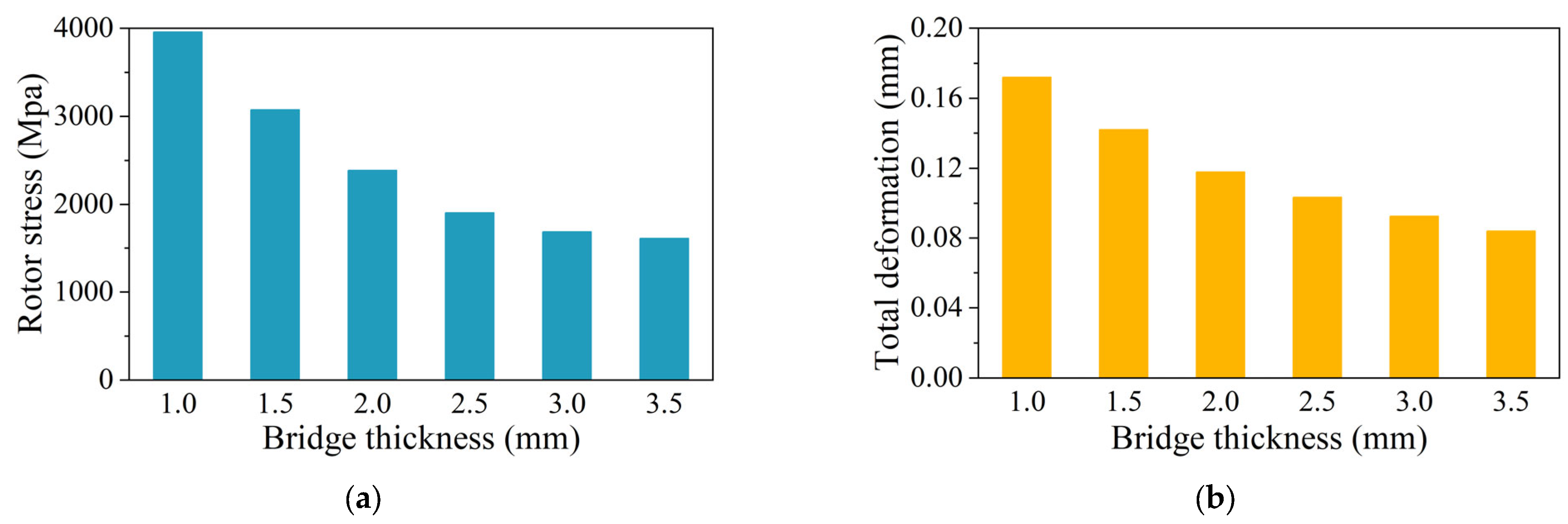
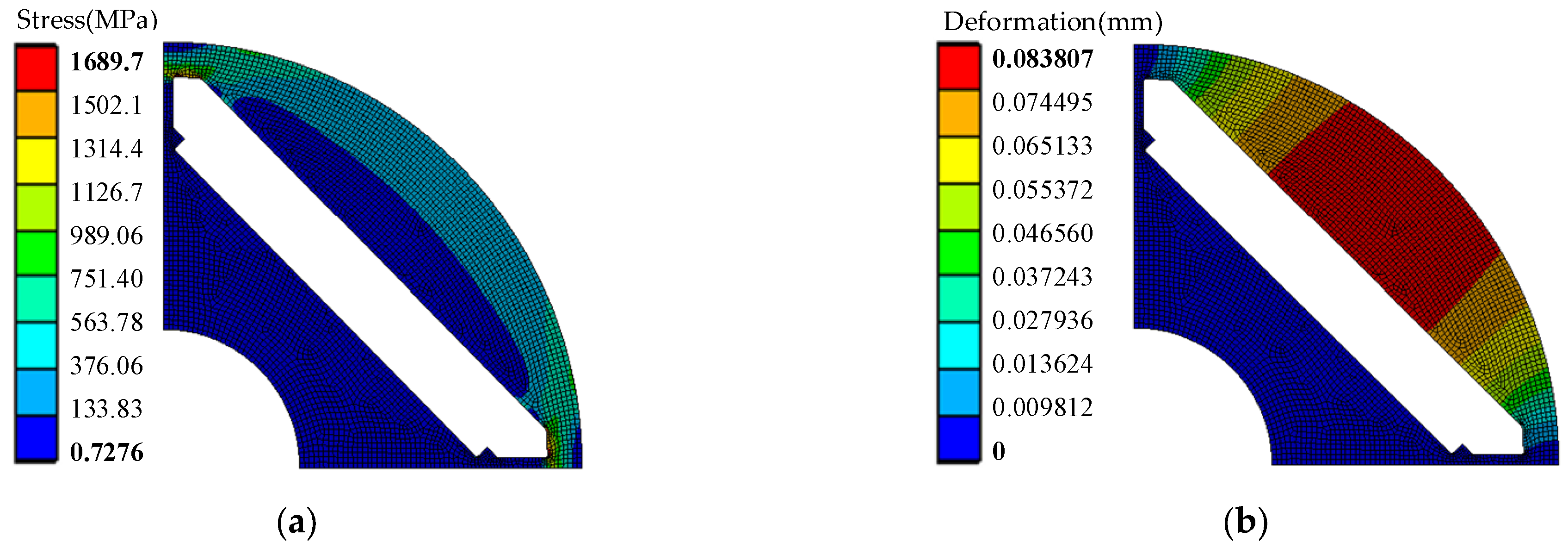
3.2. Stress Analysis of IPM Rotor

In this section, the conventional radial IPM structure is introduced, as shown in Figure 5. The distance between the PM slot and the rotor outer diameter is called magnetic bridge thickness, and the distance between each pole of the PM slot is called the rib thickness (the rib in this figure represents half of the actual distance). The centrifugal force at high speed is mainly concentrated on the magnetic bridge, which easily causes bridge damage. From the perspective of stress, the bridge is the weakest part in terms of mechanical strength. The bridge thickness should be larger to reduce stress. However, from the perspective of electromagnetic design, the size of the magnetic bridge should be as small as possible to realize magnetic saturation. Therefore, it is very important to study the influence of the magnetic bridge thickness.
The 2D-FEM is built to simulate the mechanical stress, because the PM is under compressive stress in this structure. In addition, the PM can withstand the compressive stress of 800 MPa, and has a large margin. Therefore, the stress distribution and total deformation of the rotor are mainly analyzed in this section. In the stress analysis of the IPM motor model, the contact surface between the outer surface of the PM and the rotor core is set to be in bounding contact, and the rest of the contact surfaces are in frictional contact. The results are shown in Figure 6.
It can be seen that with the gradual increase in bridge thickness, the maximum equivalent stress of the rotor decreases significantly. When the bridge thickness increases from 1 mm to 2 mm, the rotor stress decreases from 3961 MPa to 2385 MPa, reduced by 39.8%. However, when the bridge thickness increases from 2.5 mm to 3.5 mm, the rotor stress decreases from 1904 MPa to 1690 MPa, reduced by 11.2%. The total deformation also decreases from 0.104 mm to 0.084 mm, reduced by 19.2%. As the thickness of the magnetic bridge increases, the decreasing trend of rotor stress and deformation becomes slow.
Figure 7 shows the effect of bridge thickness and rib thickness on rotor stress and total deformation. It can be seen that the bridge thickness has a great influence on the rotor stress and deformation. As the bridge thickness increases, the rotor stress and deformation decrease sharply. However, the rotor stress and deformation are mildly affected by the rib thickness. With the increase of the thickness of magnetic rib, the rotor stress and deformation reduce slightly.
In this section, the effect of the bridge thickness on the rotor electromagnetic performance is analyzed. In Figure 8, the no-load leakage flux factor is illustrated when the bridge thicknesses are changed. It can be seen that the bridge thickness increases from 1 mm to 3.5 mm, the no-load leakage flux factor increases from 1.12 to 1.56, an increase of 39.3%. With the increase in bridge thickness, the no-load flux leakage factor increases gradually, which affects the electromagnetic performance of the motor. A large no-load flux leakage factor also means that the flux leakage of the motor is large while the main flux is small.
Combining the results in Figure 6, Figure 7 and Figure 8, the thickness of bridge and rib are designed to be 3.5 mm and 1.6 mm. The stress simulation results are shown in Figure 9. It is obvious that the peak point of rotor stress is located near the magnetic bridge. The total deformation is 0.084 mm, and the rotor stress is 1690 MPa. However, it is still far greater than the yield strength of 480 MPa. If the mechanical stress exceeds the ultimate strength of the material, the bridge will be severely deformed or even broken. Therefore, necessary measures should be taken to improve the mechanical reliability of the rotor.

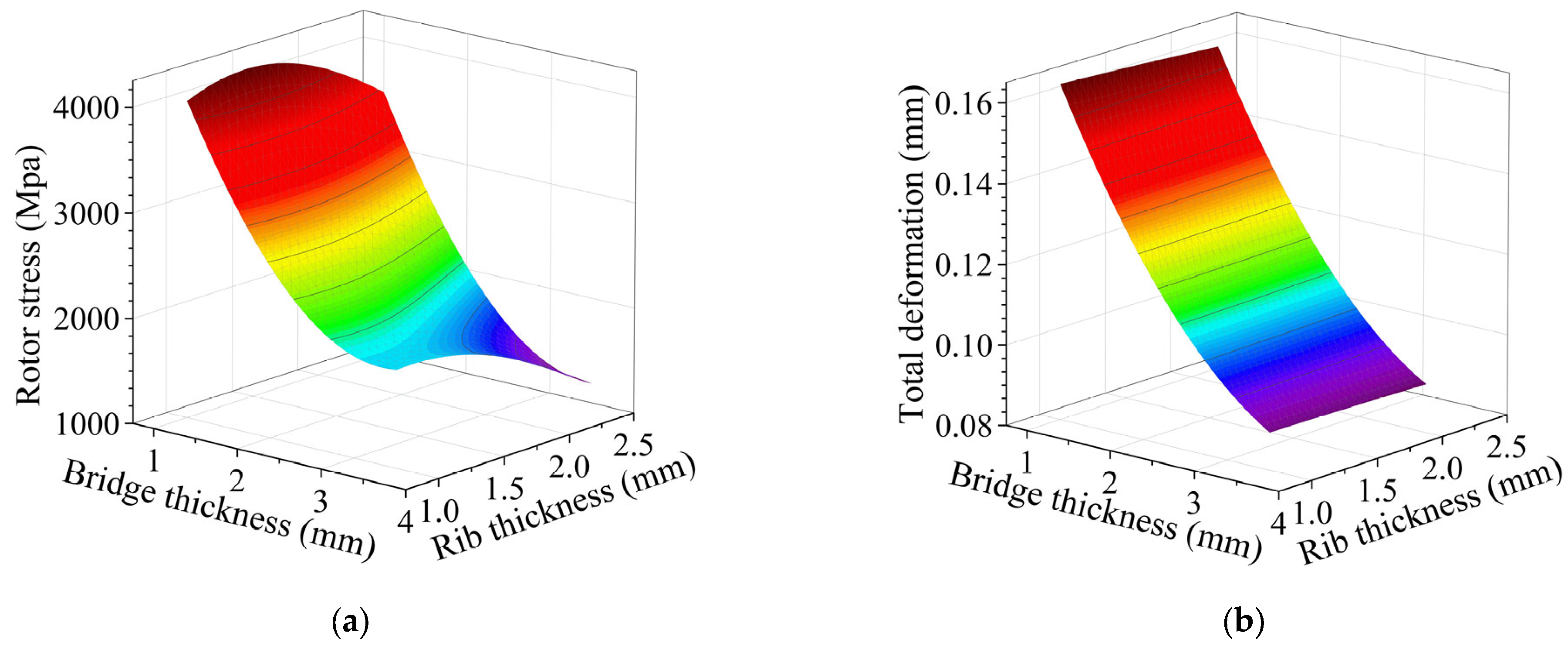
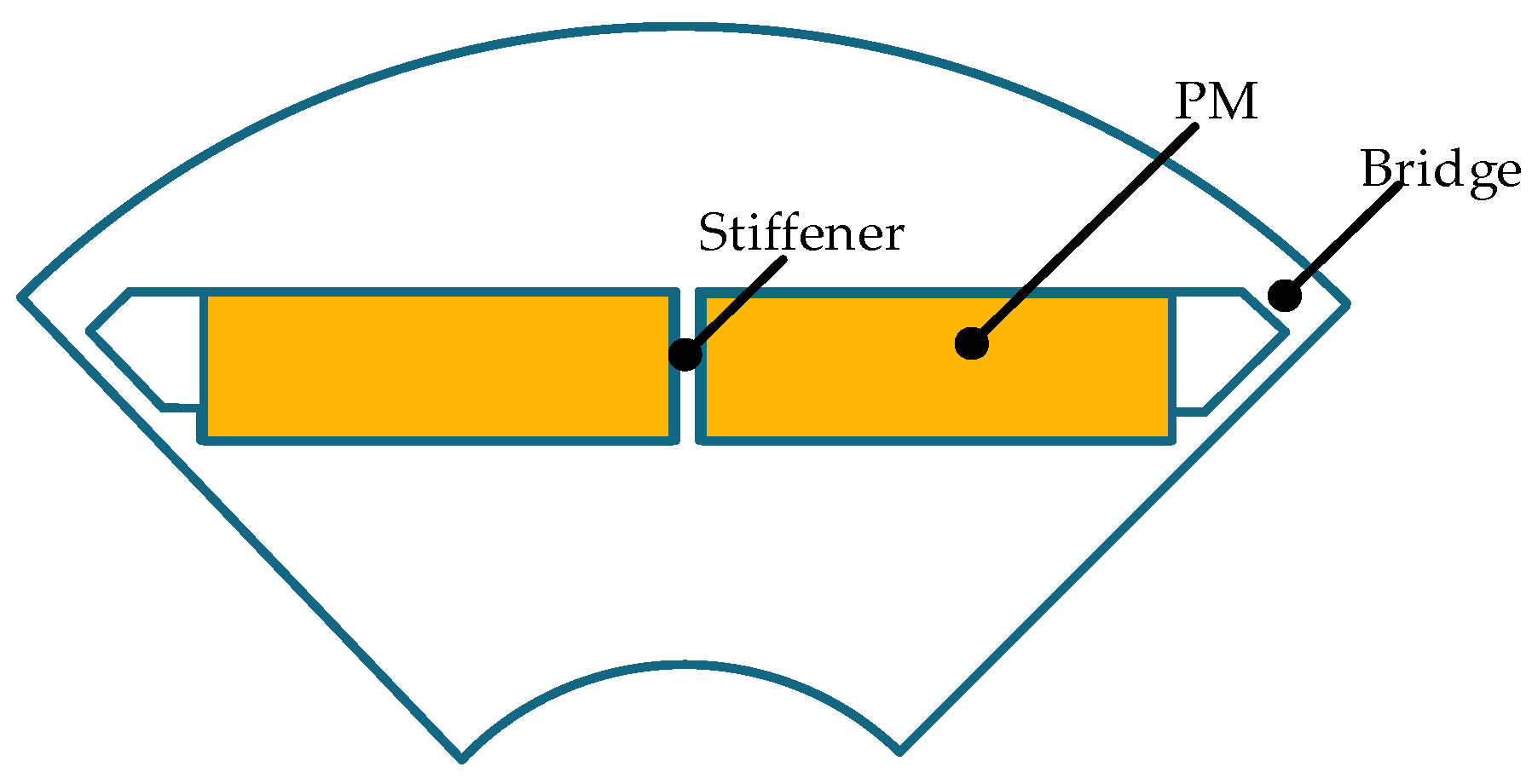
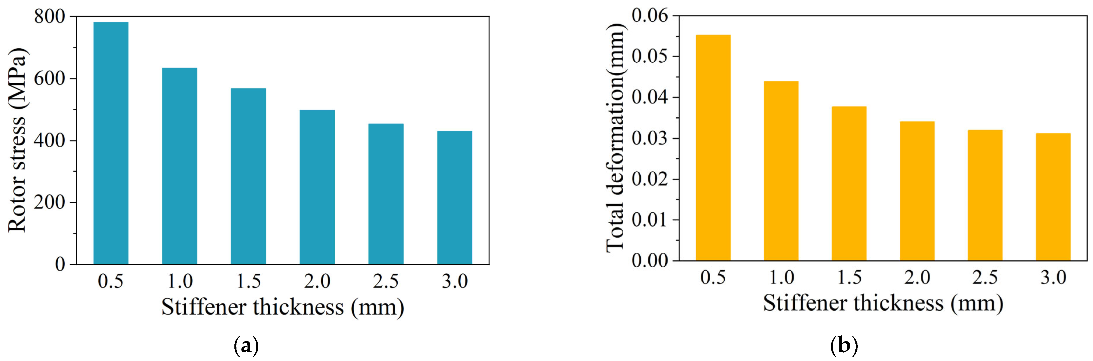
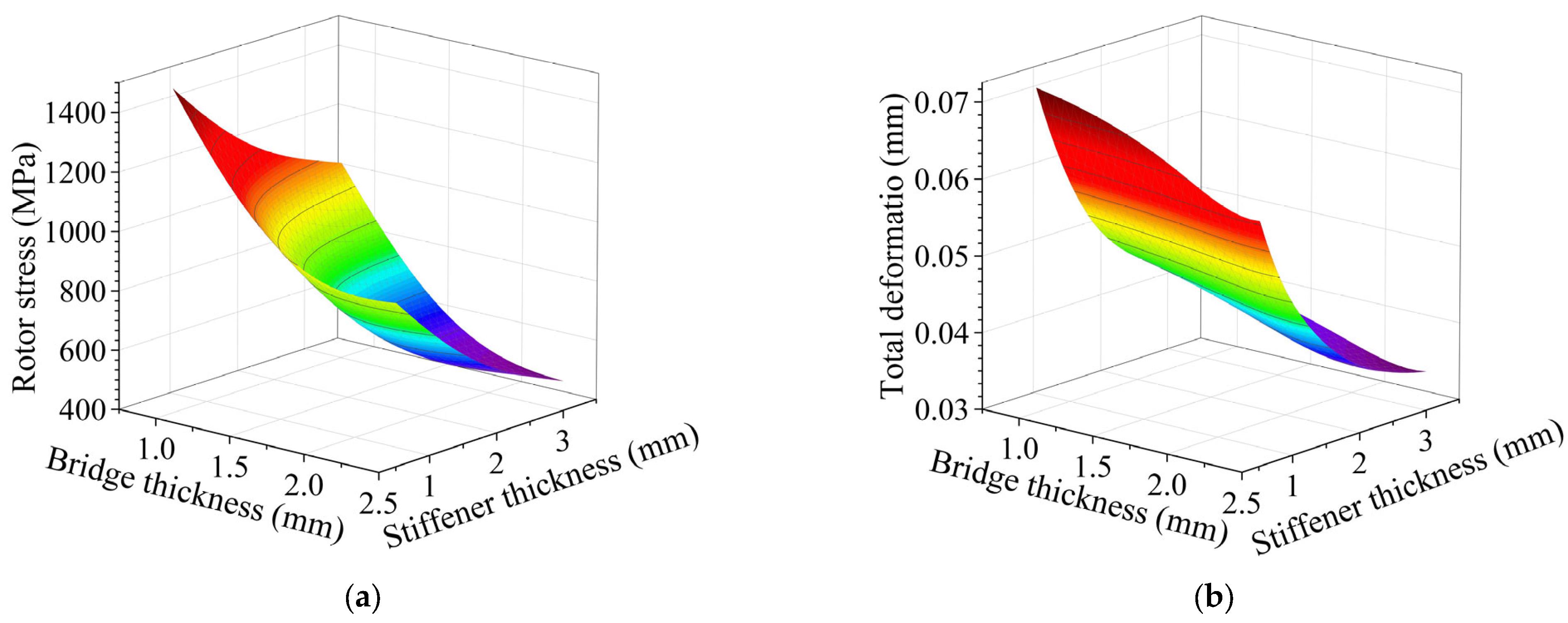
3.3. Stress Analysis of IPM Rotor with Stiffener

It is difficult for the conventional radial IPM structure to meet the stress-field constraints of an HSPMM. In order to reduce the rotor stress, the PM is segmented into two sections. A stiffener is added to disperse the centrifugal force, which was previously only borne by the magnetic bridge. The rotor structure with stiffener is shown in Figure 10.
Figure 11 shows the influence of stiffener thickness on rotor stress and total deformation. With the increase of stiffener thickness, the maximum equivalent stress on the rotor presents a decreasing trend, but the trend of decreasing is different. When the stiffener thickness is less than 2 mm, the rotor stress decreases significantly. When the stiffener thickness increases from 0.5 mm to 2 mm, the rotor stress decreases by 36.1%. When the stiffener thickness is greater than 2 mm, the declining trend of rotor stress slows down. When the stiffener thickness increases from 2 mm to 3 mm, the rotor stress decreases by 13.9%. The variation trend of total deformation is the same as that of rotor stress.
The effects of bridge thickness and stiffener thickness on rotor stress and total deformation are shown in Figure 12. When the bridge thickness and the stiffener thickness increase, the rotor stress decreases. Similarly, when the bridge thickness and the stiffener thickness increase, the total deformation of the rotor decreases. The influence of the stiffener thickness on total deformation is more obvious than that of the bridge thickness. To satisfy the stress-field constraints, the bridge thickness selected was 2.3 mm.
Dividing the PM into two sections helps to reduce the maximum stress of the rotor, but additional magnetic flux leakage paths will increase. The no-load flux leakage factor under different stiffener thicknesses is calculated through 2D-FEM, and the results are shown in Figure 13. Results show that the no-load leakage flux factor rises linearly with the increase in stiffener thickness. Therefore, on the premise of satisfying the mechanical strength, the thickness of the stiffener should be as small as possible. The stiffener thickness selected was 2.8 mm.
Considering the influence of rotor stress and the no-load leakage flux factor, the thickness of the bridge and stiffener were designed to be 2.3 mm and 2.8 mm, respectively. The simulation results are shown in Figure 14. It is obvious that the peak point of rotor stress is located at the root of the stiffener. Due to the segmented structure, the mechanical reliability of the rotor is significantly enhanced. The rotor stress is 430 MPa, and the total deformation is 0.031 mm, which also meets the stress-field constraints.
From the consideration of rotor stress, the design of rotor parameters is finally determined for the HSPMM, as shown in Table 3. Two motors with different rotor structures are designed based on the same stator design parameters, the same motor volume and the similar line back-EMF. The two motors with different structures have the same permanent magnet thickness, but a different embrace is used to ensure similar no-load back-EMF. The PM of the SPM motor is in the shape of a ring, while the IPM is a cuboid, so the volume of the two PMs is different. The permanent magnet consumption of the IPM motor is only 66.7% of that of the SPM motor. For the SPM motor, the sleeve thickness and interference fit were selected to be 5 mm and 0.15 mm, respectively. For the IPM motor, the thickness of the bridge and stiffener were designed to be 2.3 mm and 2.8 mm, respectively.
In the rotor stress analysis and comparison, both rotor structures satisfy the stress constraints. The sleeve stress of the SPM motor is 596 MPa, and the safety factor is 3.29. The rotor core stress of the IPM motor is 430 MPa, and the safety factor is 1.12. SPM motors have greater stress margins than IPM motors.

4. Analysis of Electromagnetic Performances of Two Different Rotor Structures

Based on the two rotor structures established in Section 3, the 2D-FEM is established for the HSPMMs. The electromagnetic performances of the two motors are calculated and compared by 2D FEA. In the electromagnetic simulation, the purpose of the machines is as an electric motor, which is excited with current. Besides this, the motor is simulated in two operating states: no-load and rated load. In the no-load operation state, the excitation current of the motor is 0 A, and the motor speed is 30,000 rpm. Under rated load operation, the excitation current of the motor is 132 A, and the motor speed is 30,000 rpm.

4.1. Magnetic Flux Distributions

The magnetic flux distributions are calculated under no load condition, as shown in Figure 15. The magnetic flux lines of both SPM and IPM motors are evenly distributed. However, the magnetic flux density is very different. For the SPM motor, the maximum magnetic flux density is 1.43 T, which is located in the stator yoke. For the IPM motor, the maximum magnetic flux density is 2.28 T, which is located at the magnetic bridge of the rotor core.

4.2. Line-to-Line Back-EMF

Figure 16 shown the line-to-line back-EMF and Fourier-transform results of the two different structures under no-load conditions. It is obvious that the line back-EMF of SPM is much smoother compared with that of the IPM. The total harmonic distortion (THD) of the SPM motor is 0.64% and that of the IPM motor is 3.20%. The 11th and 13th harmonics of IPM are higher than that of SPM. Besides, the no-load line back-EMF of the IPM motor is 520 V while that of the SPM motor is 538 V. The back-EMF of IPM motor is reduced for two reasons. On the one hand, in order to meet the rotor-stress design requirements, the additional flux leakage path is increased due to the addition of a stiffener on the rotor core. The no-load flux leakage factor of the IPM motor is as high as 1.72. On the other hand, due to space constraints, the PM consumption of the IPM motor is only 66.7% of that of the SPM motor. Therefore, the no-load back-EMF of the IPM motor is slightly lower than that of the SPM motor.

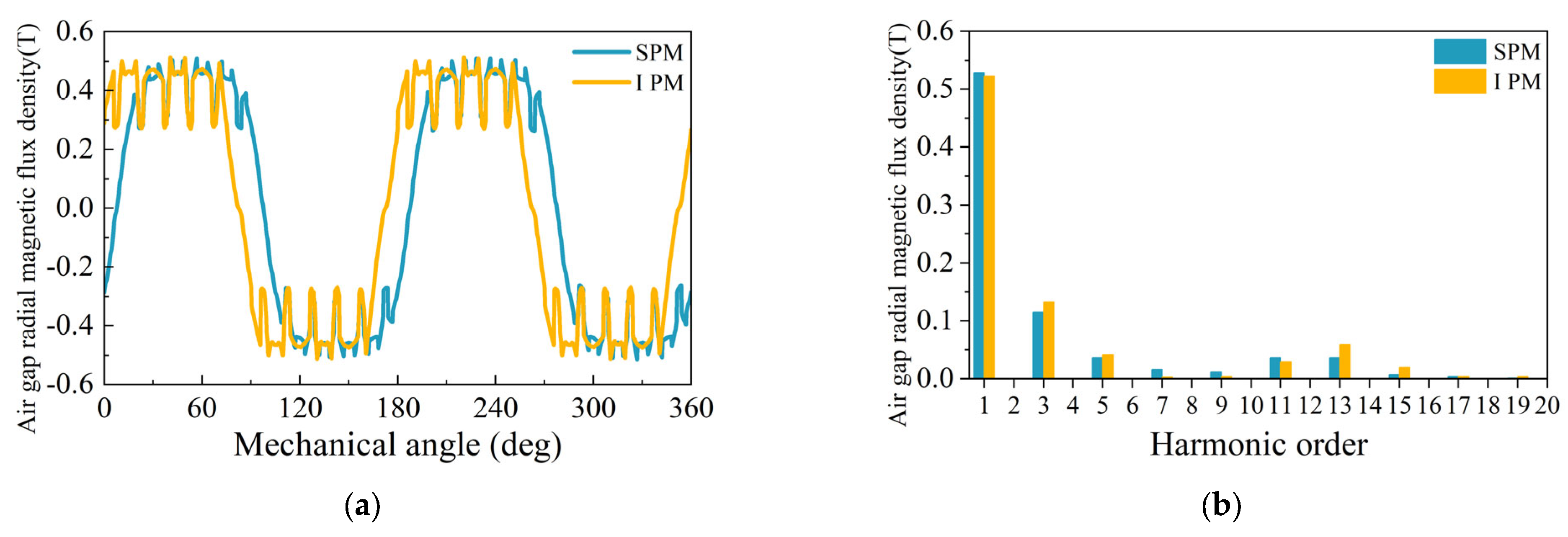
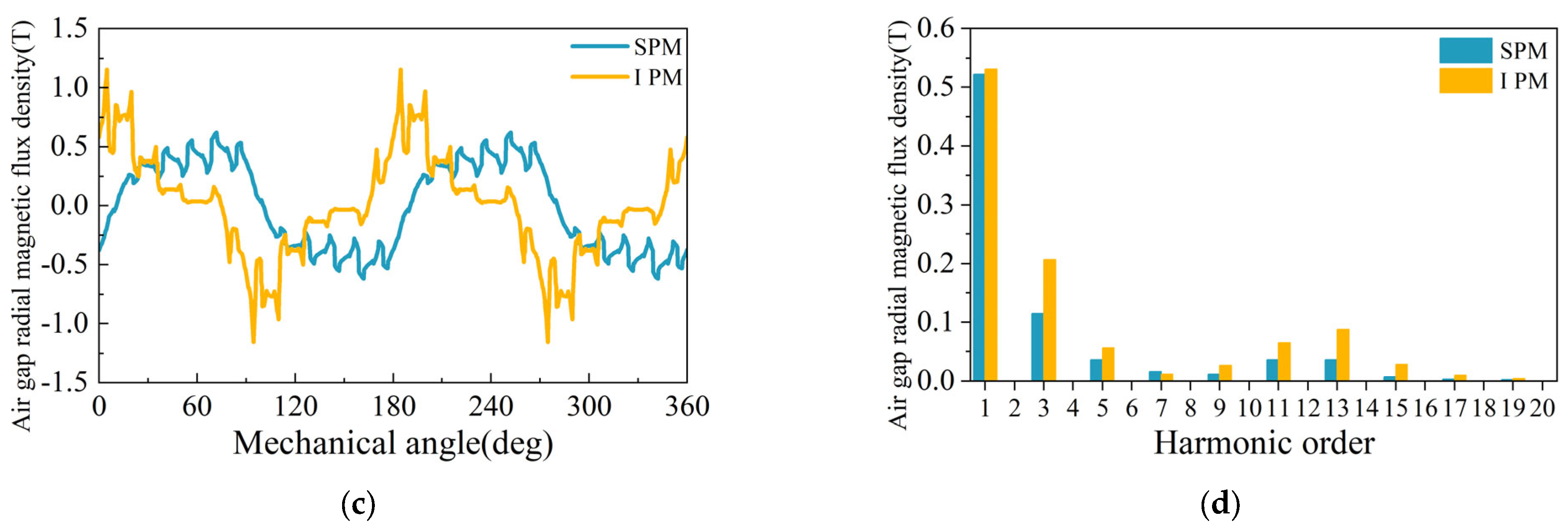
4.3. Air Gap Radial Magnetic Flux Density

Under no-load and rated load conditions, the radial air-gap flux density and Fourier-transform results of the two structures are comprehensively compared, as shown in Figure 17.
For no-load conditions, the air-gap flux density waveforms of the two motors are close to trapezoidal wave. The fundamental amplitude of SPM is slightly higher than that of IPM. This is why the back-EMF of SPM is higher than that of IPM.
For rated load conditions, both the IPM and the SPM contain high harmonic components. Due to the small air gap of the IPM motor, the stator current has a great influence on the air-gap magnetic flux density distribution of the IPM motor. In particular, the 3rd, 5th, 11th and 13th harmonic components of the two structures are high. Overall, the air-gap flux density waveforms of SPM are closer to a sine wave, and the harmonic components are much less than those of the IPM.

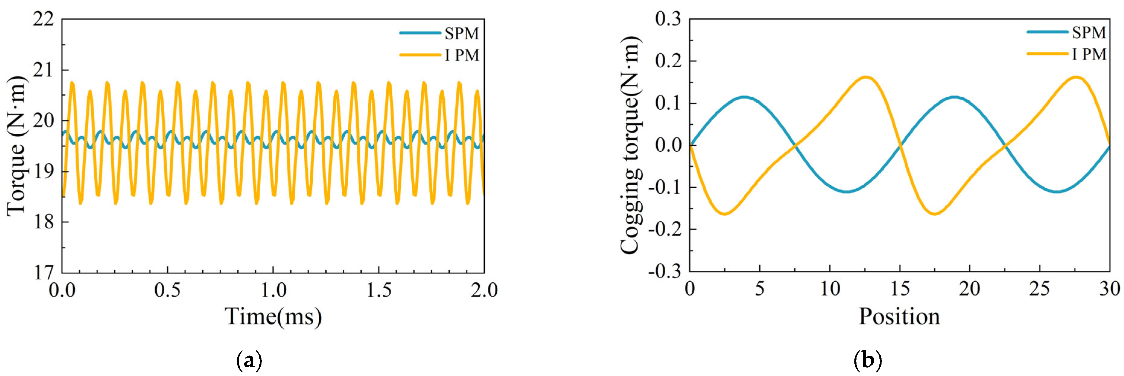
4.4. Torque and Cogging Torque Characteristics

Figure 18 shows the torque and cogging torque waveforms of the SPM and IPM motors. Calculating the average value of the second cycle, the torque of the SPM is 19.63 N·m while the torque of the IPM is 19.58 N·m. The average torque of the SPM is slightly larger than that of the IPM because the line back-EMF of the SPM is larger than that of the IPM. In addition, as can be seen from Figure 18b, the torque ripple of the SPM is smaller than that of the IPM due to the smaller cogging torque compared to the IPM motor.

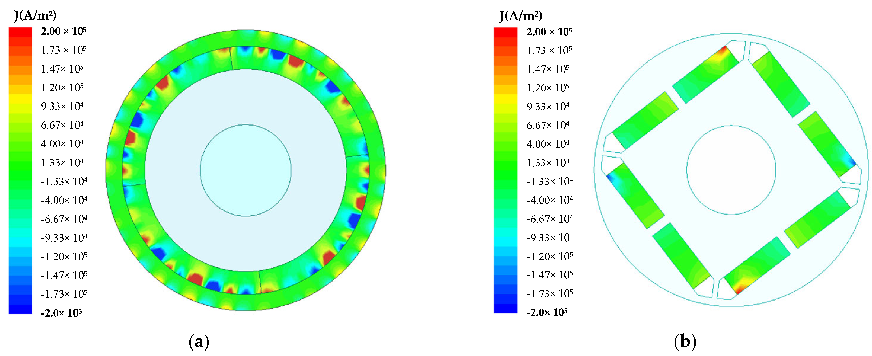
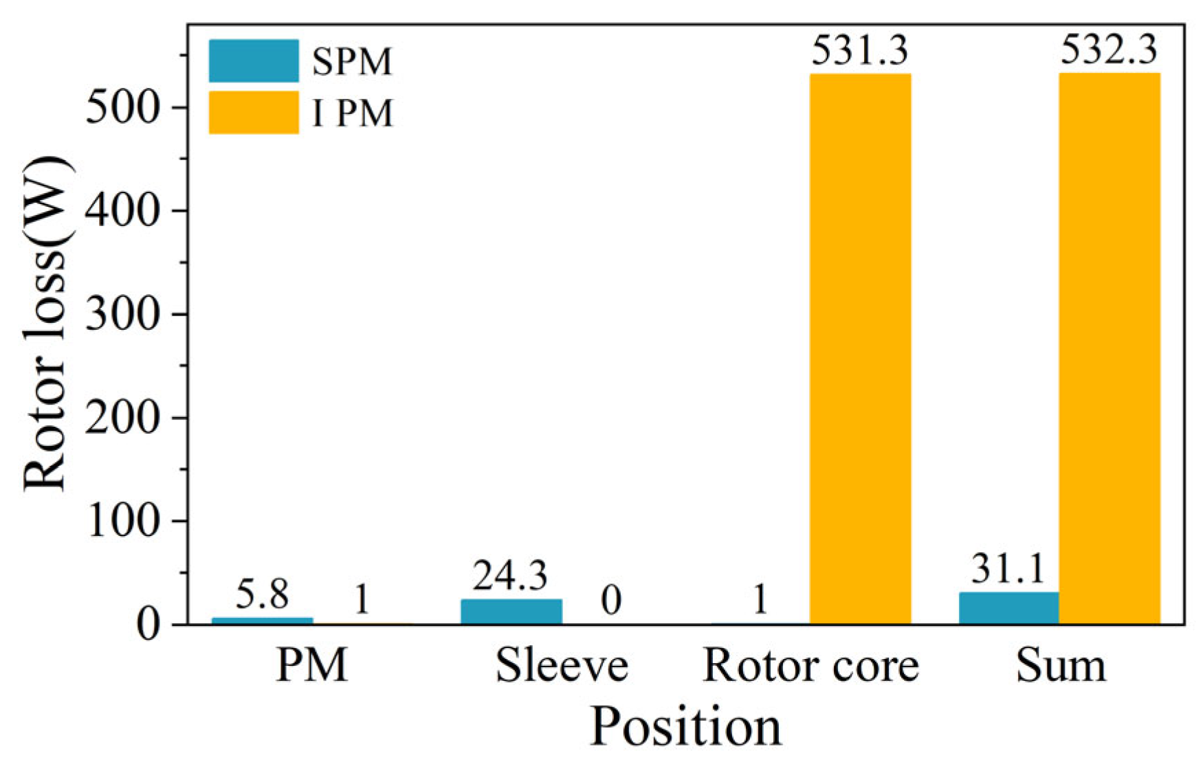
4.5. Rotor Loss Comparative Analysis

The rotor eddy-current density distribution of the two rotor structures under rated load are illustrated in Figure 19. For better comparison, the eddy-current loss distributions of the two rotor structures are presented based on the same upper and lower limits. It is observed that the maximum eddy current density occurs at the PM for both rotor structures. However, the maximum eddy-current density of the SPM motor is much higher than that of IPM motor.
The losses at each position of two rotors are calculated as shown in Figure 20. According to the eddy-current density distribution, the loss on the PM of SPM is larger than that of IPM, but the total loss of IPM is far greater than that of SPM due to the large rotor core loss. For the SPM motor, on the one hand, the eddy-current losses on the sleeve are small due to the poor electrical conductivity of the carbon-fiber sleeve. On the other hand, the losses on the rotor core of SPM motor are also small because of the large effective air gap length (including air gap length and sleeve thickness). For the IPM motor, due to the smaller air-gap length, the stator current has a greater influence on the air-gap magnetic flux density distribution, and thus the harmonic components of the air-gap flux density of the IPM motor are much larger than those of SPM motor, which would result in larger rotor core loss for the IPM motor. This results in a very noticeable difference in rotor losses for the two motors.

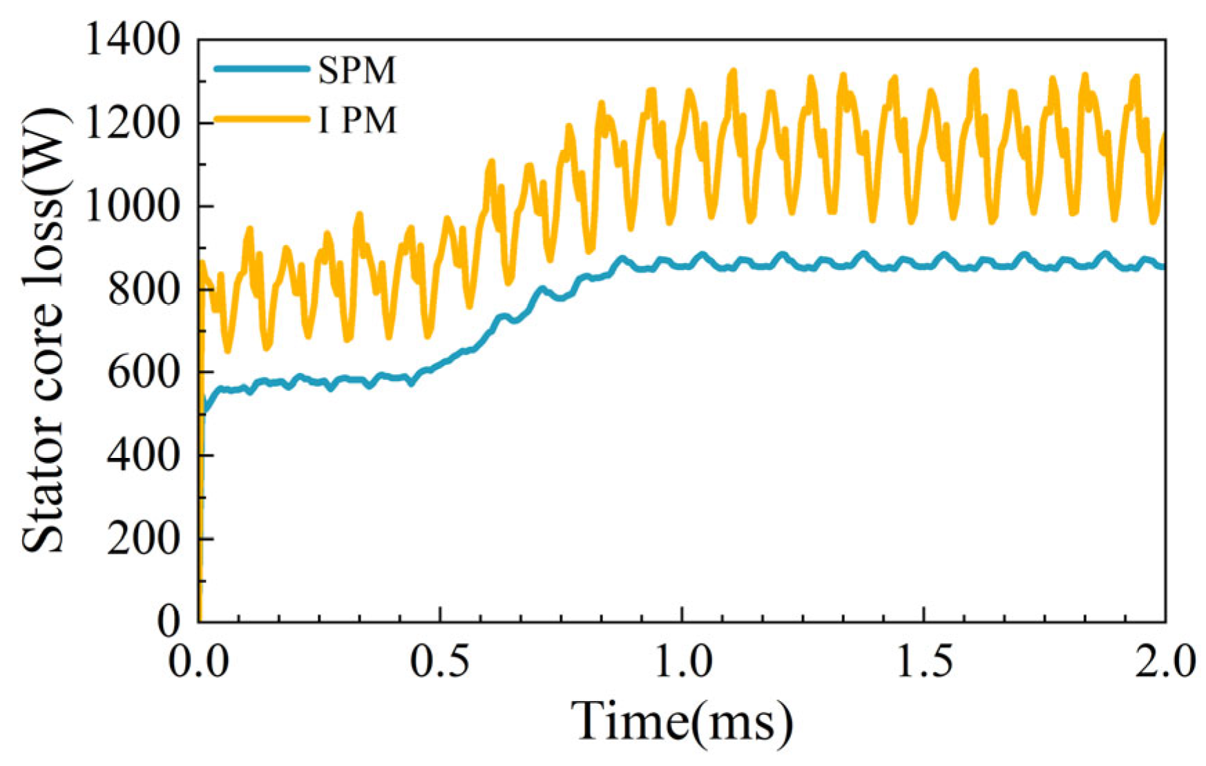
4.6. Stator Loss Comparative Analysis

The stator core loss is the main component of the total loss of the motor. In terms of theoretical analysis, due to the small air-gap length of the IPM motor, the stator current has a great influence on the air-gap magnetic flux density distribution of the motor, and thus its harmonic components of the air-gap flux density are much larger than those of the SPM motor, which would result in larger stator core loss. In terms of simulation results, the stator core loss of the SPM is 863 W while the stator core loss of IPM is 1149 W, calculating the average value of the second cycle in Figure 21. It is clear that the stator core loss of IPM is somewhat larger. The simulation results are in agreement with the theoretical analysis.

5. Temperature Distribution of Two Different Rotor Structures

So far, two motors with different structures have been compared in electromagnetic field performance. However, the HSPMM generates a lot of heat during continuous operation. In order to ensure the safety and lifetime of HSPMMs, the thermal analysis must be conducted and an excellent cooling system should be designed.

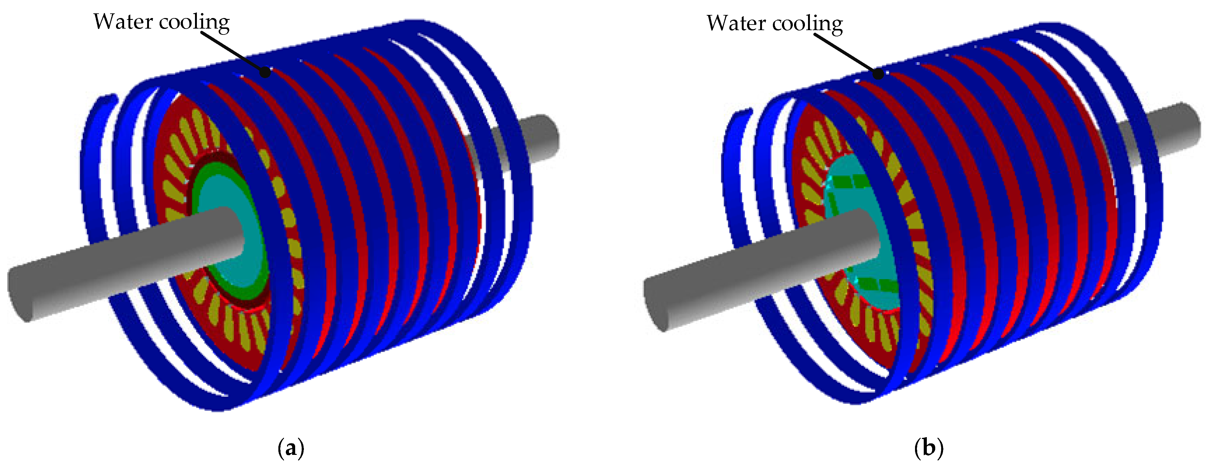
5.1. Temperature Calculation Model

The research objects of this section are two motors with different rotor structures, both of which adopt water cooling systems with a spiral waterway outside the stator. Maintaining the same cooling conditions, the thermal analysis is performed by Motor-CAD. The FEMs are shown in Figure 22. The motor is running at rated load and the motor speed is 30,000 rpm. In this design, the ambient temperature is 30 °C, and the water flow rate is set to 1 m3/h. The parameter settings of the cooling system are shown in Table 4.

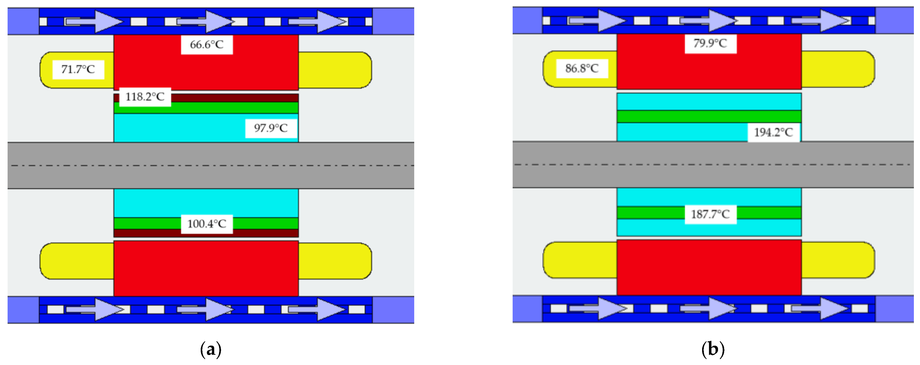
5.2. Temperature Comparative Analysis

Combined with the thermal field constraints, the maximum tolerable temperature of the rotor was set to 150 °C for increasing the reliability. Besides this, the maximum winding temperature was set to 130 °C for increasing the lifetime of the HSPMM.
The temperature distribution and comparison when the two motors run stably for a period of time are shown in Figure 23 and Figure 24. For the SPM motor, the rotor temperature is higher than that of the stator due to the poor thermal conductivity of the carbon-fiber sleeve. The maximum temperature of the motor is at the sleeve, which is about 118 °C. The maximum winding temperature is 72 °C. The maximum temperature of the stator winding and rotor satisfy the temperature-field constraints. For the IPM motor, the temperature of the rotor position is particularly high due to the large core losses. The maximum rotor temperature is 194 °C. which is much higher than the temperature-field constraints.

6. Prototype and Experiment

6.1. Comparison Summary of Multi-Physics

Combined with the rotor stress analysis in Section 3, the electromagnetic field analysis in Section 4, and the temperature-field analysis in Section 5, the multi-physics comparison results of SPM and IPM motors are shown in Table 5.
As seen from Table 5, the safety factor of rotor stress for the SPM motor is 3.29, and it is 1.12 for the IPM motor, which indicates that the SPM motor has a larger stress safety margin than the IPM motor.
In the comparative analysis of the electromagnetic field, the amplitude of no-load line back-EMF of the IPM motor is 520 V while that of the SPM motor is 538 V. Generally speaking, for the IPM motor, there is a smaller physical air-gap length due to the lack of a sleeve, and it is easy to design a larger no-load back-EMF. However, the no-load back-EMF of an IPM motor is reduced for two reasons. On the one hand, in order to meet the rotor-stress design requirements, the additional flux leakage path is increased due to the addition of a stiffener on the rotor core. The no-load flux leakage factor of the IPM motor is as high as 1.72. On the other hand, due to space constraints, the PM consumption of the IPM motor is only 66.7% of that of the SPM motor. Therefore, the no-load line back-EMF of the IPM motor is slightly lower than that of the SPM motor.
In addition, the efficiency of the IPM motor is 93.97%, which is also lower than that of the SPM motor. The low efficiency of IPM motors is due to the large losses. On one hand, for the SPM motor, the eddy-current losses on the sleeve are very small due to the poor electrical conductivity of the carbon-fiber sleeve. Besides this, the loss on the rotor core of SPM motor is also small due to the large effective air-gap length (including air-gap length and sleeve thickness). On the other hand, due to the small air-gap length of the IPM motor, the stator current has a great influence on the air-gap magnetic flux density distribution of the IPM motor, and thus the harmonic components of the air-gap flux density of the IPM motor are much larger than those of SPM motor, which would result in larger stator core loss and larger rotor core loss for IPM motor. The above reasons lead to a very obvious difference in rotor loss for the two structures.
In the analysis and comparison of the temperature field, the temperature of the rotor part is larger than that of the stator. The maximum rotor temperature of the SPM motor is 98 °C due to the poor thermal conductivity of the carbon-fiber sleeve. Although the IPM rotor structure has good heat-dissipation performance, the temperature of the rotor core is as high as 194 °C due to the large loss. It can be seen that the rotor temperature of the SPM motor is much lower than that of the IPM.
Compared with the SPM motor, the IPM motor has a larger reluctance torque, so the IPM motor has better constant power range and field-weakening control performance. When a larger speed expansion through field weakening is required, the IPM motor will have a large advantage over the SPM motor. The motors in this paper are usually used in rated operation, and there is no requirement on the performance of speed expansion through field weakening.

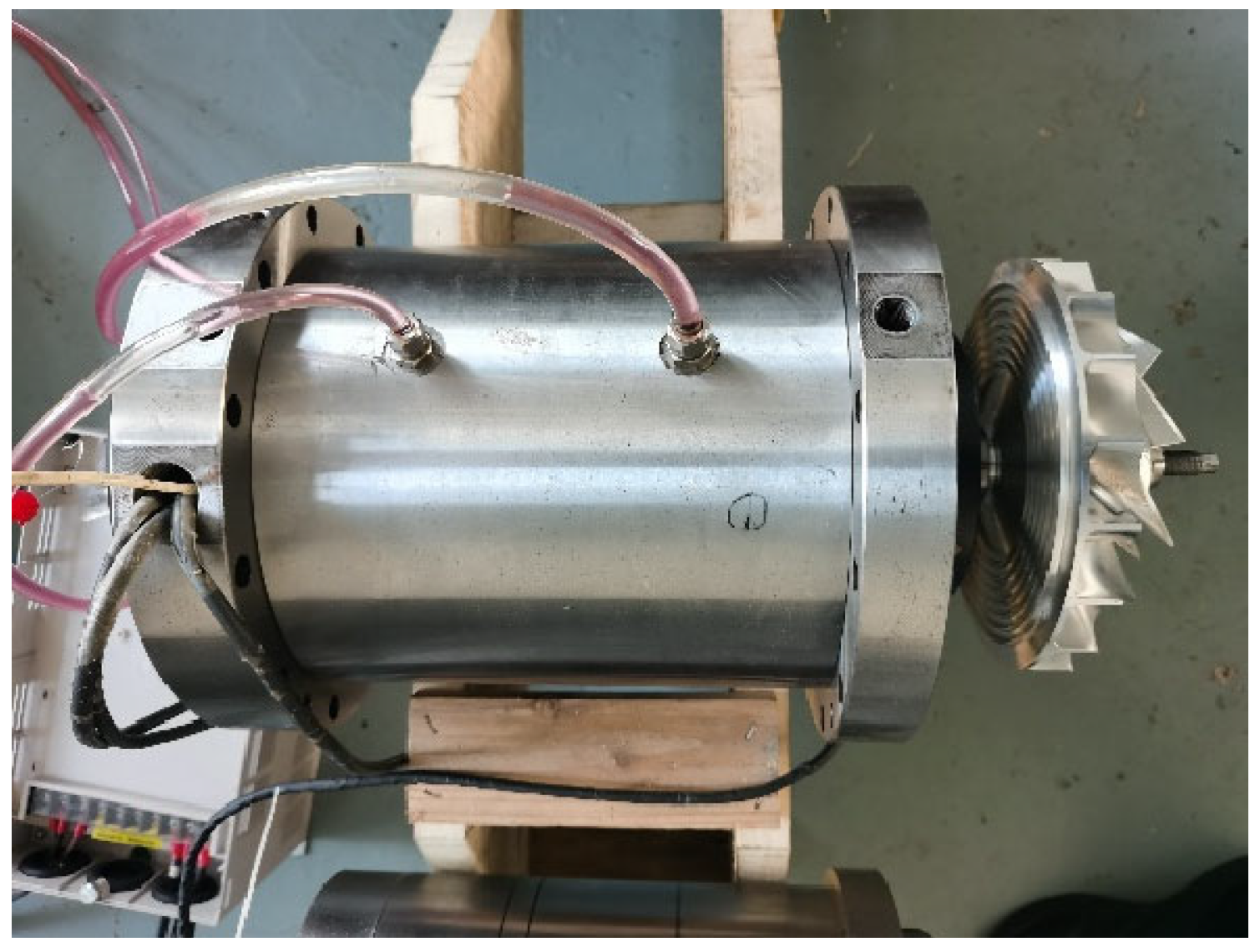
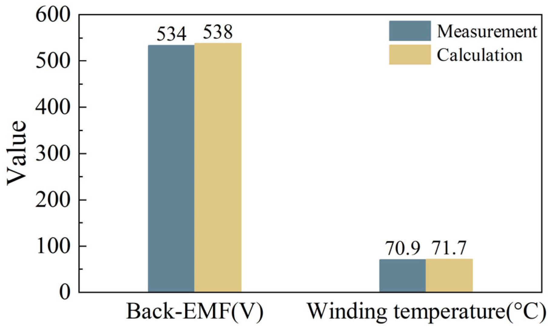
6.2. Prototype Experiment

Based on the above multi-physics comparative analysis, the SPM motor can satisfy the constraints of each field, including stress-field constraints, electromagnetic field constraints and temperature-field constraints. Therefore, a prototype of SPM rotor structure for 60 kW and 30,000 rpm was selected and manufactured, as shown in Figure 25.
In addition, the electromagnetic characteristics and temperature distribution of the SPM prototype were tested. The test results are shown in Figure 26. The no-load back-EMF test result of the prototype is 534 V while the calculated value is 538 V, with an error of 0.7%. The test result of the stator winding temperature of the prototype is 70.9 °C while the calculated value is 71.7 °C; the error is 1.1%. The total loss of the prototype is 3120 W, which is close to the calculated result. It is obvious that the experimental results of the electromagnetic field and temperature field are in good agreement with the simulation results. Besides, the prototype was operated at 30,000 rpm for 3 h. During this period, the prototype has been running securely and stably, which shows that the stress field of this design is also reasonable.
Overall, the results of the prototype test show that the SPM prototype meets the constraints of multi-physics fields, including the stress field, electromagnetic field and temperature field.

7. Conclusions

In this paper, the comprehensive performance of SPM and IPM rotor structures is compared and analyzed based on multiple physical fields, including rotor stress, the electromagnetic field and the temperature field. The two different rotor structures are analyzed and compared by multi-physical finite element models. The results show that the SPM rotor structure satisfies all the multi-physics constraints. The following conclusions can be drawn from the results of simulation and experiment:
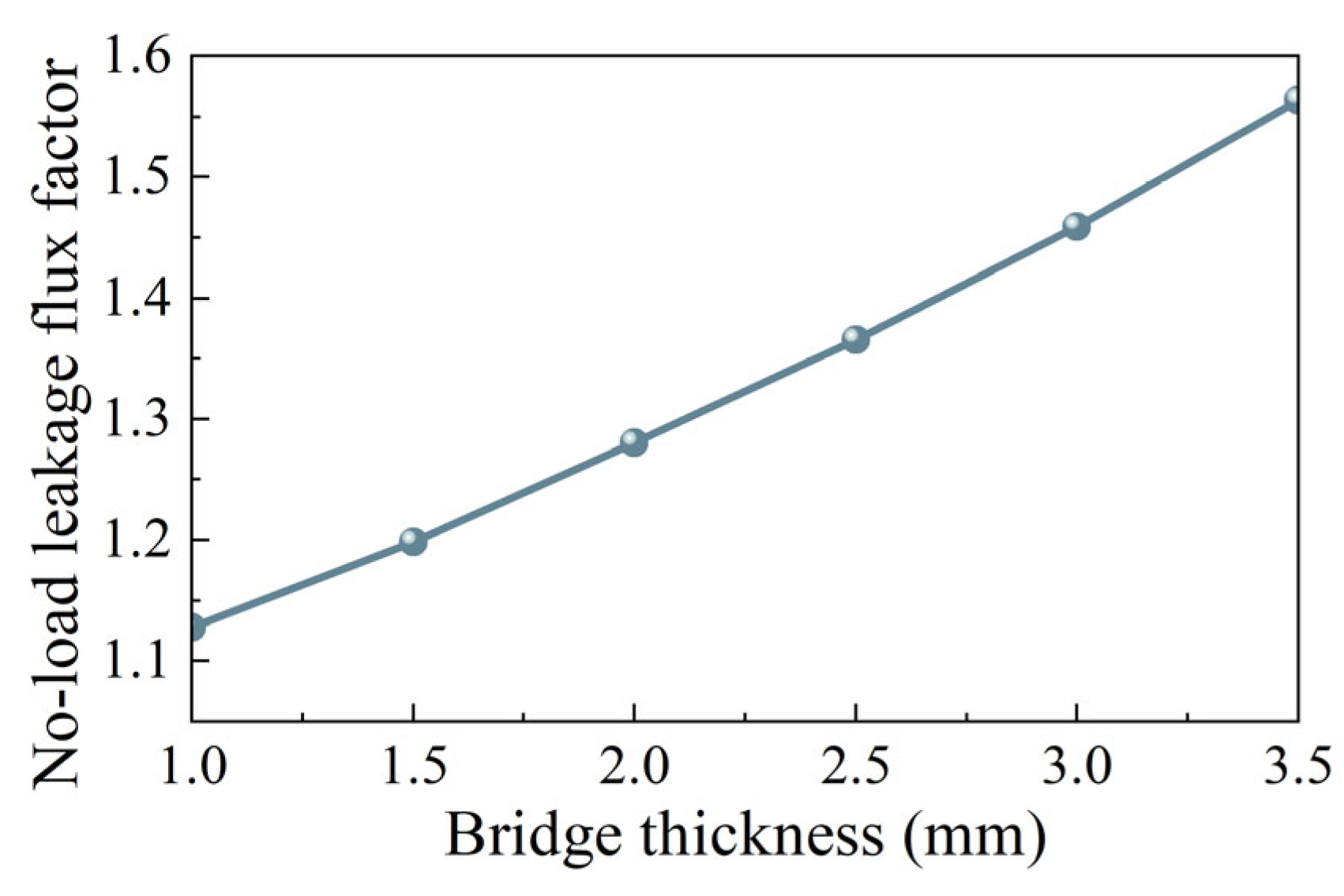
  • For the rotor stress analysis and comparison, both rotor structures meet the stress constraints, but the IPM has a small margin. As the sleeve thickness of SPM increases, the equivalent stress of the sleeve and the tangential stress of PM decrease. When the sleeve thickness is 5 mm, the sleeve stress is 596 MPa, while the yield strength of the carbon-fiber sleeve is 1960 MPa. The IPM structure has a conflict between rotor flux leakage and rotor stress. The traditional radial structure cannot meet the stress constraints. When the thickness of the magnetic bridge is 3.5 mm, the rotor stress is 1690 MPa, which is much larger than the yield strength of the rotor corn of 480 MPa. Dividing the PM into two sections and adding a stiffener can effectively reduce the rotor stress. When the stiffener thickness is 2.8 mm, the leakage flux factor is as high as 1.72, and the rotor stress is 430 MPa, which is close to the yield strength of the rotor core.
  • For the electromagnetic field analysis and comparison, the loss of the two rotor structures is quite different, and the performance of other aspects is similar. Compared with IPM, the line back-EMF and air-gap flux density waveforms of SPM are closer to sine waves. The torque of SPM is slightly greater than that of IPM. In addition, the rotor loss of IPM is 532 W while the rotor loss of SPM is 31 W. The stator core loss of IPM is 1149 W while the stator core loss of SPM is 863 W.
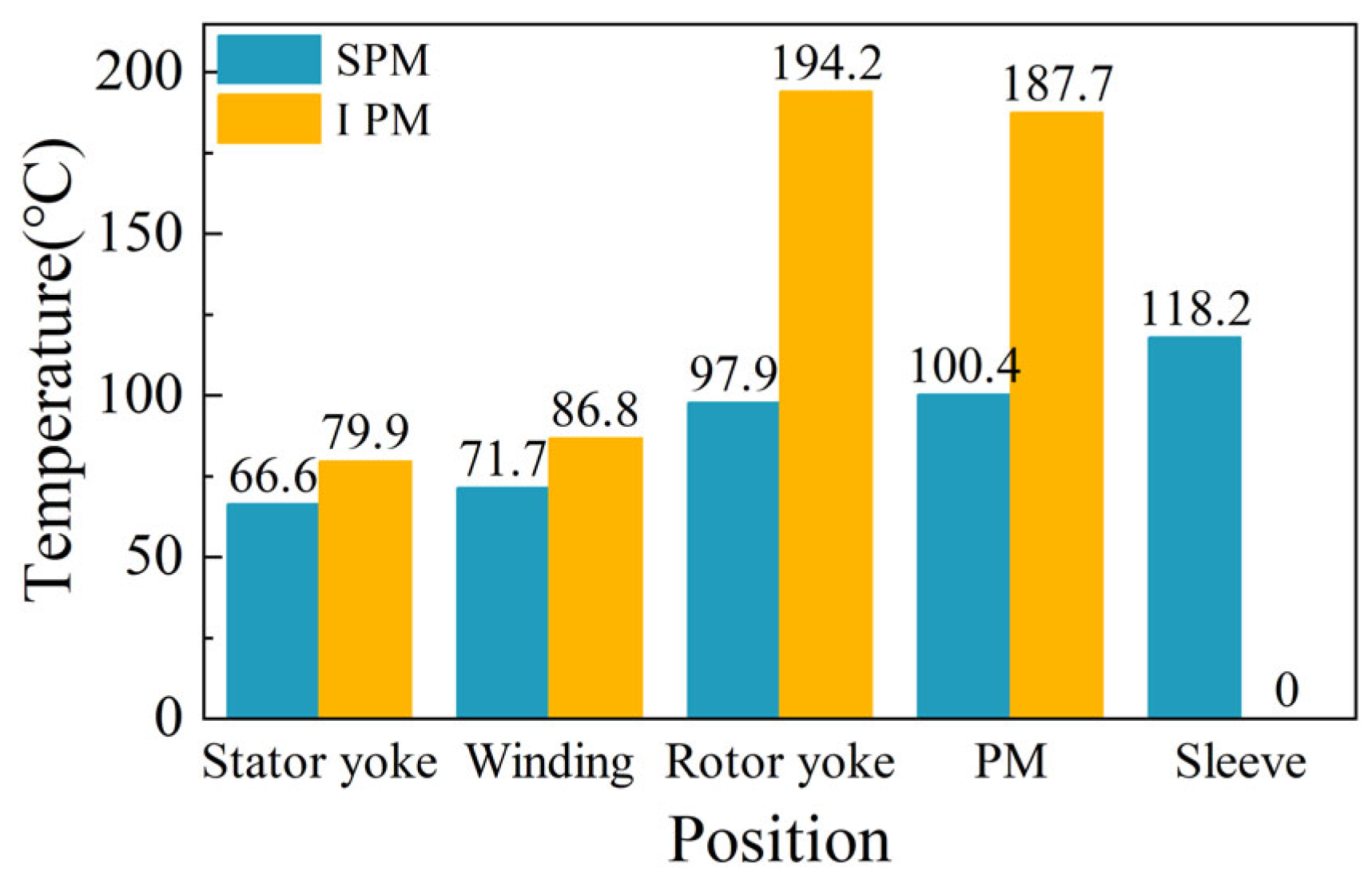
  • For the temperature-field analysis comparison, the temperature difference of the rotor part is larger than that of the stator part for the two rotor structures. The stator temperature of SPM is 66.6 °C while the stator temperature of IPM is 79.9 °C. The rotor temperature of SPM is 98 °C due to the poor thermal conductivity of the carbon-fiber sleeve. Although the IPM rotor structure has better heat dissipation performance, the rotor temperature is as high as 194 °C due to large losses. The IPM temperature distribution does not satisfy the temperature-field constraints.

Author Contributions

Conceptualization, G.D. and Q.Z.; Data curation, G.D. and N.L.; Formal analysis, N.L.; Funding acquisition, G.D.; Investigation, G.D. and N.L.; Methodology, G.D. and N.L.; Project administration, G.D.; Resources, G.D.; Software, N.L.; Supervision, Q.Z.; Validation, G.D., Q.Z., W.G., L.W. and T.P.; Visualization, N.L.; Writing—original draft, N.L.; Writing—review and editing, G.D., N.L., W.G., L.W. and T.P. All authors have read and agreed to the published version of the manuscript.

Funding

This research was funded by National Nature Science Foundation of China, grant number 52177056.

Institutional Review Board Statement

Not applicable.

Informed Consent Statement

Not applicable.

Data Availability Statement

Not applicable.

Conflicts of Interest

The authors declare no conflict of interest.

References

  1. Du, G.H.; Huang, N.; He, H.C.; Lei, G.; Zhu, J.G. Parameter Design for a High-Speed Permanent Magnet Machine Under Multiphysics Constraints. IEEE Trans. Energy Convers. 2020, 35, 2025–2035. [Google Scholar] [CrossRef]
  2. Hou, P.; Ge, B.J.; Tao, D.J.; Pan, B.; Wang, Y. Rotor Strength Analysis of FeCo-Based Permanent Magnet High Speed Motor. Machines 2022, 10, 462. [Google Scholar] [CrossRef]
  3. Qi, Z.N.; Zhang, Y.; Yu, S.Y.; Xu, Z.Y. Design and Analysis of a 30 KW, 30,000 r/Min High-Speed Permanent Magnet Motor for Compressor Application. Energies 2022, 15, 3923. [Google Scholar] [CrossRef]
  4. Lin, Y.Z.; Huang, Y.K.; Zhang, T. Comprehensive Design and Analysis of Rotor Stress for HSPMM Considering Cooling Method. Machines 2022, 10, 475. [Google Scholar] [CrossRef]
  5. Hong, J.F.; Wang, S.M.; Yang, Z.L. Comparison of Electromagnetic Excited Vibration for SPM and IPM Motors. In Proceedings of the 2017 19th European Conference on Power Electronics and Applications (EPE’17 ECCE Europe), Warsaw, Poland, 11–14 September 2017; IEEE: Piscataway, NJ, USA, 2017; pp. 1–8. [Google Scholar]
  6. Pellegrino, G.; Vagati, A.; Guglielmi, P.; Boazzo, B. Performance Comparison Between Surface-Mounted and Interior PM Motor Drives for Electric Vehicle Application. IEEE Trans. Ind. Electron. 2012, 59, 803–811. [Google Scholar] [CrossRef]
  7. Ahn, J.H.; Han, C.; Kim, C.W.; Choi, J.Y. Rotor Design of High-Speed Permanent Magnet Synchronous Motors Considering Rotor Magnet and Sleeve Materials. IEEE Trans. Appl. Supercond. 2018, 28, 5201504. [Google Scholar] [CrossRef]
  8. Chu, G.Y.; Dutta, R.; Rahman, M.F.; Lovatt, H.; Sarlioglu, B. Analytical Calculation of Maximum Mechanical Stress on the Rotor of Interior Permanent-Magnet Synchronous Machines. IEEE Trans. Ind. Appl. 2020, 56, 1321–1331. [Google Scholar] [CrossRef]
  9. Du, G.H.; Xu, W.; Zhu, J.G.; Huang, N. Rotor Stress Analysis for High-Speed Permanent Magnet Machines Considering Assembly Gap and Temperature Gradient. IEEE Trans. Energy Convers. 2019, 34, 2276–2285. [Google Scholar] [CrossRef]
  10. Du, G.H.; Xu, W.; Huang, N.; Cheng, X.; Xiao, X.Y. Rotor Design of High Power High Speed Permanent Magnet Machine Considering Multiphysics Constraints. In Proceedings of the 2019 22nd International Conference on Electrical Machines and Systems (ICEMS), Harbin, China, 11–14 August 2019; pp. 1–5. [Google Scholar]
  11. Li, W.L.; Qiu, H.B.; Zhang, X.C.; Cao, J.C.; Zhang, S.N.; Yi, R. Influence of Rotor-Sleeve Electromagnetic Characteristics on High-Speed Permanent-Magnet Generator. IEEE Trans. Ind. Electron. 2014, 61, 3030–3037. [Google Scholar] [CrossRef]
  12. Wang, L.; Du, G.H.; Tong, J.; Huang, N.; Hu, C.S.; Xu, W. Comparation of Different Rotor Sleeves of Highspeed Permanent Magnet Synchronous Motors Based on Multi-Physics. In Proceedings of the 2021 IEEE 4th Student Conference on Electric Machines and Systems (SCEMS), Huzhou, China, 1–3 December 2021; IEEE: Piscataway, NJ, USA, 2021; pp. 1–5. [Google Scholar]
  13. Xia, Y.; Li, J.; Qu, R.H.; Fang, H.Y. Comparison of Two Rotor Topologies for High-Speed Permanent Magnet Synchronous Machines. In Proceedings of the 2016 XXII International Conference on Electrical Machines (ICEM), Lausanne, Switzerland, 4–7 September 2016; IEEE: Piscataway, NJ, USA, 2016; pp. 1419–1425. [Google Scholar]
  14. Liu, X.P.; Zhang, Z.X.; Xiao, J.J.; Xu, H. Comparison and Analysis of Electromagnetic Characteristics of IPMSM with Single and Double Layer PMs. JAE 2018, 58, 483–496. [Google Scholar] [CrossRef]
  15. Yang, Y.Y.; Castano, S.; Yang, R.; Kasprzak, M.; Bilgin, B.; Sathyan, A.; Dadkhah, H.; Emadi, A. Design and Comparison of Interior Permanent Magnet Motor Topologies for Traction Applications. IEEE Trans. Transp. Electrif. 2017, 3, 86–97. [Google Scholar] [CrossRef]
  16. Kim, S.I.; Kim, Y.K.; Lee, G.H.; Hong, J.P. A Novel Rotor Configuration and Experimental Verification of Interior PM Synchronous Motor for High-Speed Applications. IEEE Trans. Magn. 2012, 48, 843–846. [Google Scholar] [CrossRef]
  17. Dong, J.N.; Huang, Y.K.; Jin, L.; Lin, H.Y. Comparative Study of Surface-Mounted and Interior Permanent-Magnet Motors for High-Speed Applications. IEEE Trans. Appl. Supercond. 2016, 26, 5200304. [Google Scholar] [CrossRef]
  18. Zhao, N.N.; Liu, W.G. Loss Calculation and Thermal Analysis of Surface-Mounted PM Motor and Interior PM Motor. IEEE Trans. Magn. 2015, 51, 8112604. [Google Scholar] [CrossRef]
  19. Tao, P.; Du, G.H.; Tong, J.; Huang, N.; Li, N.M.; Xu, W. Comparison of Rotor Strength of Various Rotor Structures for Ultra-High-Speed Permanent Magnet Synchronous Motor. In Proceedings of the 2021 IEEE 4th Student Conference on Electric Machines and Systems (SCEMS), Huzhou, China, 1–3 December 2021; IEEE: Piscataway, NJ, USA, 2021; pp. 1–6. [Google Scholar]
  20. Fang, H.Y.; Li, D.W.; Qu, R.H.; Li, J.; Wang, C.; Song, B. Rotor Design and Eddy-Current Loss Suppression for High-Speed Machines with a Solid-PM Rotor. IEEE Trans. Ind. Applicat. 2019, 55, 448–457. [Google Scholar] [CrossRef]
Figure 1. Two different model of the motor: (a) Model of SPM motor; (b) Rotor structure of SPM motor; (c) Model of IPM motor; (d) Rotor structure of IPM motor.
Machines 10 00700 g001
Figure 2. The influence of different factors on sleeve and PM stress: (a) Sleeve thickness; (b) Interference fit.
Machines 10 00700 g002
Figure 3. The influence of sleeve thickness and interference fit on sleeve stress and PM stress: (a) Equivalent stress of sleeve; (b) Tangential stress of PM.
Machines 10 00700 g003
Figure 4. Simulation results: (a) Equivalent stress of sleeve; (b) Tangential stress of PM; (c) Deformation of sleeve; (d) Deformation of PM.
Machines 10 00700 g004
Figure 5. The structure of a conventional IPM rotor.
Machines 10 00700 g005
Figure 6. The influence of bridge thickness on rotor stress and total deformation: (a) Maximum equivalent stress of rotor; (b) Total deformation.
Machines 10 00700 g006
Figure 7. The influence of bridge thickness and rib thickness on rotor stress and total deformation: (a) Maximum equivalent stress of rotor; (b) Total deformation.
Machines 10 00700 g007
Figure 8. Relationship between no-load leakage flux factor and bridge thickness.
Machines 10 00700 g008
Figure 9. Simulation results: (a) Rotor stress; (b) Total deformation.
Machines 10 00700 g009
Figure 10. The IPM rotor structure with stiffener.
Machines 10 00700 g010
Figure 11. The influence of stiffener thickness on rotor stress and total deformation: (a) Maximum equivalent stress of rotor; (b) Total deformation.
Machines 10 00700 g011
Figure 12. The influence of stiffener thickness and bridge thickness on rotor stress and total deformation: (a) Maximum equivalent stress of rotor; (b) Total deformation.
Machines 10 00700 g012
Figure 13. Relationship between no-load leakage flux factor and stiffener thickness.
Machines 10 00700 g013
Figure 14. Simulation results: (a) Rotor stress; (b) Total deformation.
Machines 10 00700 g014
Figure 15. Magnetic flux distributions of SPM and IPM under no load: (a) SPM; (b) IPM.
Machines 10 00700 g015
Figure 16. Line-to-line back-EMF of SPM and IPM under no load: (a) SPM; (b) IPM.
Machines 10 00700 g016
Figure 17. Air-gap radial magnetic flux density of SPM and IPM under no load and rated load: (a) Air-gap radial magnetic flux density with mechanical angle waveform at no load; (b) Fourier transform at no load; (c) Air-gap radial magnetic flux density with mechanical angle waveform at rated load; (d) Fourier transform at rated load.
Machines 10 00700 g017aMachines 10 00700 g017b
Figure 18. Torque and cogging torque of SPM and IPM under rated load: (a) Torque; (b) Cogging torque.
Machines 10 00700 g018
Figure 19. Rotor eddy-current density distribution of SPM and IPM under rated load: (a) SPM; (b) IPM.
Machines 10 00700 g019
Figure 20. Rotor loss distribution of the two rotor structures under rated load.
Machines 10 00700 g020
Figure 21. Stator iron core losses of the two rotor structures under rated load.
Machines 10 00700 g021
Figure 22. Motor cooling system design: (a) SPM; (b) IPM.
Machines 10 00700 g022
Figure 23. The temperature distribution of different rotor structures: (a) SPM; (b) IPM.
Machines 10 00700 g023
Figure 24. The temperatures on the different positions at rated speed.
Machines 10 00700 g024
Figure 25. Prototype photo.
Machines 10 00700 g025
Figure 26. Prototype test results.
Machines 10 00700 g026
Table 1. The main parameters of 60-kW HSPMM.
ParametersValues
Rated power (kW)60
Rated speed (rpm)30,000
Rated voltage (V)380 (RMS)
Stator slot number
Pole number
24
4
Stator inner diameter (mm)
Axial length (mm)
90
110
Rotor outer diameter (mm)86
Permanent magnet thickness (mm)7
Air-gap length (mm)2
PM materialN38UH
Table 2. Rotor material properties.
Material PropertiesRotor CorePMCarbon Fiber
TangentialRadial
Density (kg/m3)785074001800
Elastic modulus (GPa)2001601258.8
Poisson’s ratio0.30.240.280.015
CTE 1 (10−6/K)118−0.3828
Yield strength (MPa)480751960−100
1: CTE is short for coefficient of thermal expansion.
Table 3. Two kinds of rotor structure design parameters.
ParametersSPMIPM
Embrace10.83
Permanent magnet thickness (mm)77
Permanent magnet width (mm)6040
Sleeve thickness (mm)5-
Interference fit (mm)0.15-
Rib thickness (mm)-1.6
Bridge rib thickness (mm)-2.3
Reinforcement thickness-2.8
Sleeve/rotor core stress (MPa)596430
Stress safety factor3.291.12
Table 4. The parameters of the cooling system.
ParametersValues
Water temperature (°C)30
Water flow rate (m3/h)1
Spiral channel width (mm)10
Spiral channel spacing (mm)10
Table 5. Multi-physics comparison results for two motors.
ParametersSPMIPM
Permanent magnet thickness (mm)77
Permanent magnet width (mm)6040
No-load flux leakage factor11.72
Sleeve/rotor core stress (MPa)596430
Stress safety factor3.291.12
Fundamental amplitude of back-EMF (V)538526
THD of back-EMF0.64%3.20%
Torque (N·m)19.6319.58
Rotor Loss (W)31.1532.3
Stator Loss (W)8631149
Efficiency95.27%93.97%
Maximum temperature of winding (°C)71.786.8
Maximum temperature of rotor core (°C)97.9194.2
Publisher’s Note: MDPI stays neutral with regard to jurisdictional claims in published maps and institutional affiliations.

