1. Introduction
Heavy lifting and carrying, frequent trunk bending, and regular squatting are considered risk factors for lumbar spine injuries in working environments. The current trend is toward mechanization in industry and the use of mechanical aid devices during manual handling tasks. Despite these insights, when loads are within the human lifting ability range, the workers are willing to lift manually. Most of the mechanical lifting equipment is slower than human speed and is sometimes not easily accessible. Thus, to assist the worker, we apply a system that can assist the waist movement in the direction of anti-gravity. Exoskeletons as on-body lifting aids facilitate robotic support while preserving human flexibility and intelligence [
1]. Exoskeletons can be defined as wearable bionic devices equipped with powerful actuators at human joints that integrate human intelligence and robot power [
2]. Wearable hip or trunk exoskeleton suits are necessary interventions currently being developed to help workers prevent lumbar spine injury. They can relieve back pain and avoid injuries by reducing the muscular effort or lumbar stress required for balancing or holding heavy objects [
3,
4]. Generally, the system is configured to transmit assistive torque to a wearer’s torso through actuators at both hip joints.
Various lumbar support exoskeletons have been developed and commercialized for real industrial environments to support workers and prevent back injuries [
5]. However, research efforts are still carried out for the development of lighter and more powerful exoskeletons for enhanced performance in terms of assistance. Depending on the nature of the assistive force or torque required, exoskeleton actuators can be classified into passive and active types. Passive lumbar support exoskeletons use viscoelastic elements, such as springs and dampers to assist in lifting tasks. Several of these exoskeletons have been developed, such as WMRD [
6], SPEXOR [
7], BNDR [
8], Laevo [
9], and BackX [
10]. Both WMRD and the hip joint of SPEXOR use coil springs, while BNDR employs compact torsion springs. WMRD provides a 54% reduction in back muscle activity, and SPEXOR generates an assistive torque with a 16% reduction in muscle activity by utilizing flexible beams combined with coil springs. BNDR reduces the lumbar compression load without transferring the load to the joints, thus reducing the compression and sheer force of the low back by 13% and 12%, respectively. Laevo and BackX utilize gas springs to provide passive assistance to reduce lumbar muscle fatigue even though these actuators are not considered lightweight. Several passive exoskeletons use elastic bands, such as Personal Lift Assistive Device (PLAD) [
11], Smart Suit Lite (SSL) [
12], Wearable Assistive Device (WAD) [
13], and biomechanically assistive garments [
14]. PLAD adopts elastic bands to reduce 38% of the spinal muscle activity during the squat posture. Furthermore, VT/Lowe’s exoskeleton [
15] applies carbon fiber beams to provide higher assistive torques when compared with gas springs, reducing the peak and average of back muscle activity by 31.5% and 29.3%, respectively.
These passive exoskeletons are incapable of producing enough power and assistance to reduce muscle activity [
16]. For this reason, active lumbar exoskeletons have been developed to add external energy to human motion by using a power source to activate the actuators. These exoskeleton designs comprise one or more actuators that augment the human power and help to actuate the human joints with, for example, electric motors, pneumatic artificial muscles (PAMs), hydraulic actuators, and soft actuators [
17]. Some examples of exoskeletons with motor actuators are SIAT-WEXv1 [
18], SIAT-WEXv2 [
16], Hyundai H-WEX v1 back-support [
5], Hybrid Assistive Limb (HAL) [
19], ATOUN Model A, and Y [
20]. SIAT-WEXv1 uses a DC motor with a harmonic drive to provide the assistive torque and a clutch to increase the battery-powered run time, while SIAT-WEXv2 uses a quasi-direct drive to assist the hip joint during a lifting task, leading to a reduced rate of EMG at the lumbar erector spinae (LES) of monotonically 40% to 60%. A single actuator mounted on the back of the H-WEXv1 exoskeleton has been designed and integrated with a wire drive to transfer the motion to the hip joint for lifting objects. The main muscle activities have been reached by 10% to 30%. Perhaps the best-known developed robotic suit is Cyberdyne’s Hybrid Assistive Limb (HAL). The HAL for care support has enabled to reduce the magnitude of muscle force (lumbar erector spinae (LES) declined by 14%) and the onset of muscle activity (LES reduced by 4.5%) in the lower back during a repetitive lifting task [
19]. Consequently, it can be seen that most of the active exoskeletons use electric motors [
21], even though there are some examples of using pneumatic actuators (e.g., Muscle Suit [
22]) or hydraulic actuators [
23].
One of the significant problems associated with the current active actuators of exoskeletons is that they are rigid and stiff. They cannot, therefore, effectively adapt to unpredicted external impact loads or obstacles and thus produce high impedance and resistance to any dynamic behavior of human movement. To mitigate the drawbacks and safety risks of rigid actuator designs, the mechanical configuration of the elastic element with an electric motor has been proposed. This configuration provides many advantages over rigid actuators [
24], such as low mechanical output impedance, back-drivability, tolerance to impact loads, high force/torque controllability, and fidelity. It has been found that only a few studies in the application of lumbar support exoskeleton adopted the configuration of the elastic element-electric motor. An example of a parallel arrangement is the active trunk module (Robo-Mate) [
25], which incorporates a parallel-elastic actuator (PEA) to meet the torque requirements of manual handling of the object in industrial environments. It provides a significant reduction in muscular activity in the lumbar spine (around 30%). Another configuration is the series elastic actuator (SEA), where two studies are noted in the literature for lumbar support exoskeleton at hip joints. The lower back exoskeleton [
26] uses four SEA units with a clutch to generate effective assistance, providing a continuous torque of approximately 40 Nm on both hip joints to actively assist both hip abduction/adduction and hip flexion/extension. H-WEXv2 [
27] utilizes a SEA-based wire-driven mechanism, as reported, the muscle intensity of the erector spinae and gluteus maximus are reduced by 33.0% and 41.6% in semi-squatting posture, respectively.
Lumbar support exoskeletons with active actuators demand power sources (e.g., batteries) that increase the device’s overall weight and limit their operational time due to increased battery consumption during the entire cycle of the lifting task. A passive exoskeleton, on the other hand, can only provide limited assistance to users due to the physical nature of passive device components. Moreover, current studies of passive actuators for lumbar support applications do not consider the biomechanical energy conversion and management of lower limbs during the phases of lifting tasks, which involve periodic motion acceleration and deceleration. According to the different energy conversion forms, elastic energy is one form of physical-mechanical energy storage that is pollution-free, reusable, and low cost. Therefore, the exoskeleton acquires the biomechanical energy from the negative power of the lower limbs and then supports the acceleration of the lower limbs during the lifting task. Hence, the exoskeleton can assist in lifting in the absence of external force, which is a very promising idea.
Passively storing and releasing energy might be accomplished mechanically through the practical use of a mechanical spring. Since a mechanical spring system has properties similar to the human lower limb muscle–tendon unit and thus may compensate for the function of muscle–tendon units partly, the spring can store and absorb the kinetic energy of the deceleration phase during the lifting task. In this case, biological energy consumption can be reduced, and lifting assistance can be accomplished. The concept of energy transfer between the human joint and exoskeleton has been investigated, such as the study of the unpowered knee exoskeleton [
28] that utilizes a crossing four-bar mechanism integrated with a torsion spring to reduce the energy consumption during cycling with no additional power supply. However, in the application of a lifting task exoskeleton, the hip joint’s energy transfer concept has not yet been incorporated into functional designs.
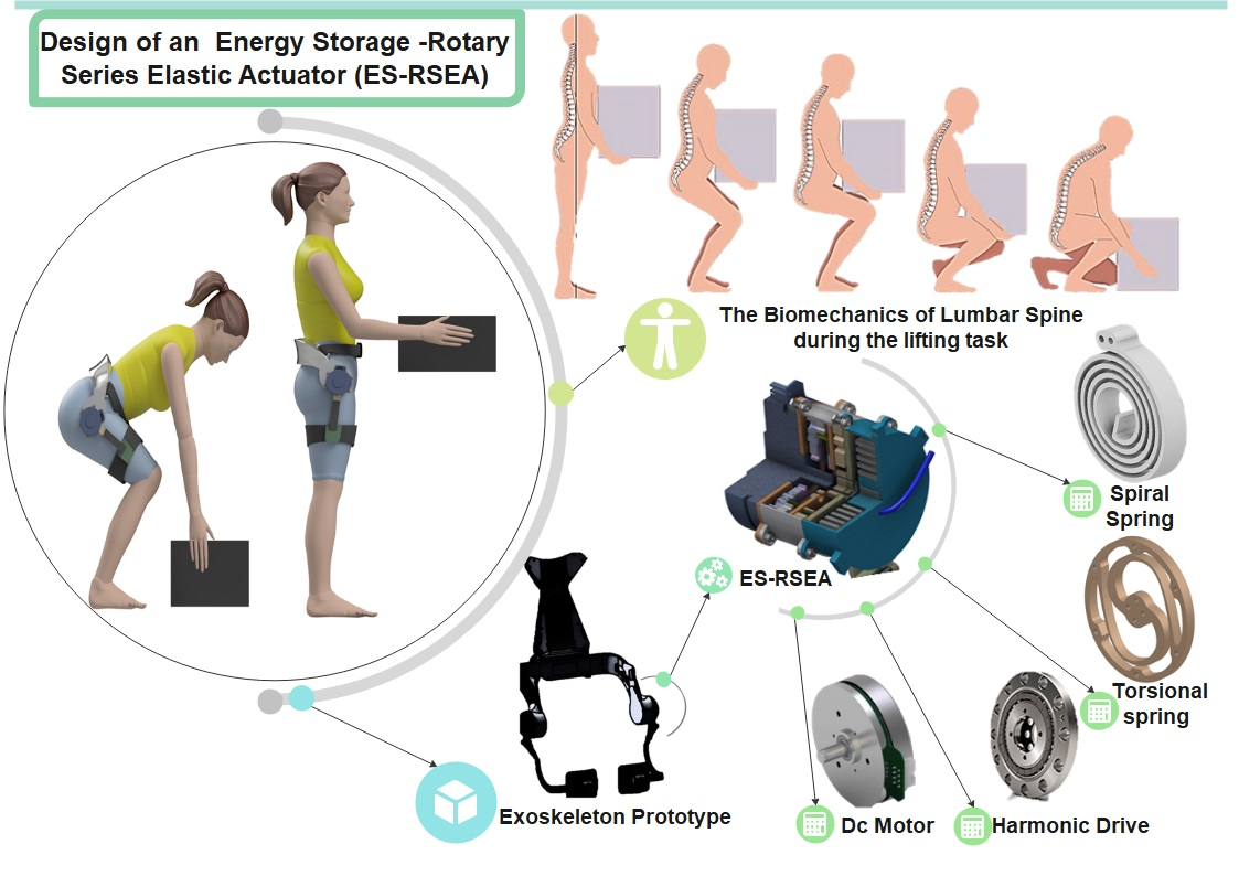
Thus, to resolve the issue of exoskeleton dependence on a large power supply and at the same time save human bioenergy and increase the level of assistance, achieve the function of energy storage, conversion, and management, this paper presents the design energy storage unit integrated with a rotary series elastic actuator (ES-RSEA) for lumbar support exoskeleton applications, to assist the hip movement during lifting tasks by utilizing the negative work of the lower limbs. The exoskeleton mainly consists of a spring storage unit, where the flat spiral spring stores mechanical energy from the lower limb descent stage and then releases it to assist the acceleration motion. The research work presented in this paper aims to provide an alternative method to harness the kinetic energy of the human limb to assist semi-squat lifting tasks along with an active compliance actuator. The paper’s main contribution is a new actuation system that utilizes the advantage of the dynamic movement of the human body during the lifting of loads to store energy and release additional output power to enhance the function of the lifting strategy for an exoskeleton and reduce battery consumption. To the authors’ knowledge, this study is the first to propose an SEA with an energy storage unit (a spiral spring) in a compact and modular design for a lumbar support exoskeleton to improve energy migration, assistance across human lower limbs, and mechanical safety.
2. Biomechanics of Lifting Task
Load lifting is a standard energy-consuming industrial operation [
29]. Low back pain and back injuries can occur as a worker lifts an object continuously, holds heavy loads in a static pose, and twists back due to a heavy load [
5]. Of the various lifting techniques, the most often employed are squat, semi-squat, and stoop lifting. Each lifting technique has been stated to possess benefits and challenges based on differences in the occupational environment, as there is no single best posture technique for all situations [
30]. The semi-squat lift technique may be considered a good compromise between the stoop and squat. Workers may also find this to be closer to the natural movement pattern for lifting tasks and more practical in most environments. Therefore, it is adopted to be the main technique for designing the proposed exoskeleton.
There are various kinds of energy conversions taking place during the daily tasks carried out by human beings. In the process of human movement, a significant amount of kinetic energy will be generated in the human body, reaching 200 W [
31]. One of the most critical aspects is the human squat. In the squat lifting cycle, since the lower limbs sustain and bend the whole body forward, they provide substantial kinetic energy in the ascent and descent movement stages. Potential energy and kinetic energy are continuously converted within the body throughout the squat lifting phase. Consider that an additional mechanism device is utilized in the deceleration phase to absorb the kinetic energy of the lower limb and transform it into potential energy, and temporarily store it for the next acceleration phase of the limb joint. In that case, biological energy consumption can be reduced, and lifting assistance can be accomplished.
2.1. Human Musculoskeletal System
Skeletal muscle contractions, the most significant tissue function in the body, contribute to 40 percent of the body weight, reinforcing the body’s different movements and breathing behavior. Multiple body joint motions are performed by the bone and joint cooperating through the contraction and release of skeletal muscle. The muscle contraction occurs due to stimulation of the motor neuron by receiving an electrical signal caused by either artificial electricity or the body’s own response. Muscle contraction operates and functions on the skeletal bars connected to it to provide muscular tension to relieve outward resistance or pressure, rotating around the joints. Moreover, muscles often include various contraction activities depending on the different movement phases within the lower limb activities [
32].
The muscle drives the movement of the joint. Through the tendon attached to the bone, the muscle transmits the driving torque and force of the joint to the human body. The lower limb muscles contract, stretching the joints and generating torque on them during squat lifting. The mechanical work of joint movement describes the transfer of energy from one part of the body to another [
32,
33]. During squat lifting tasks, muscles can generate both positive and negative mechanical work. Muscles convert the metabolic energy of the human body into mechanical energy when doing positive work.
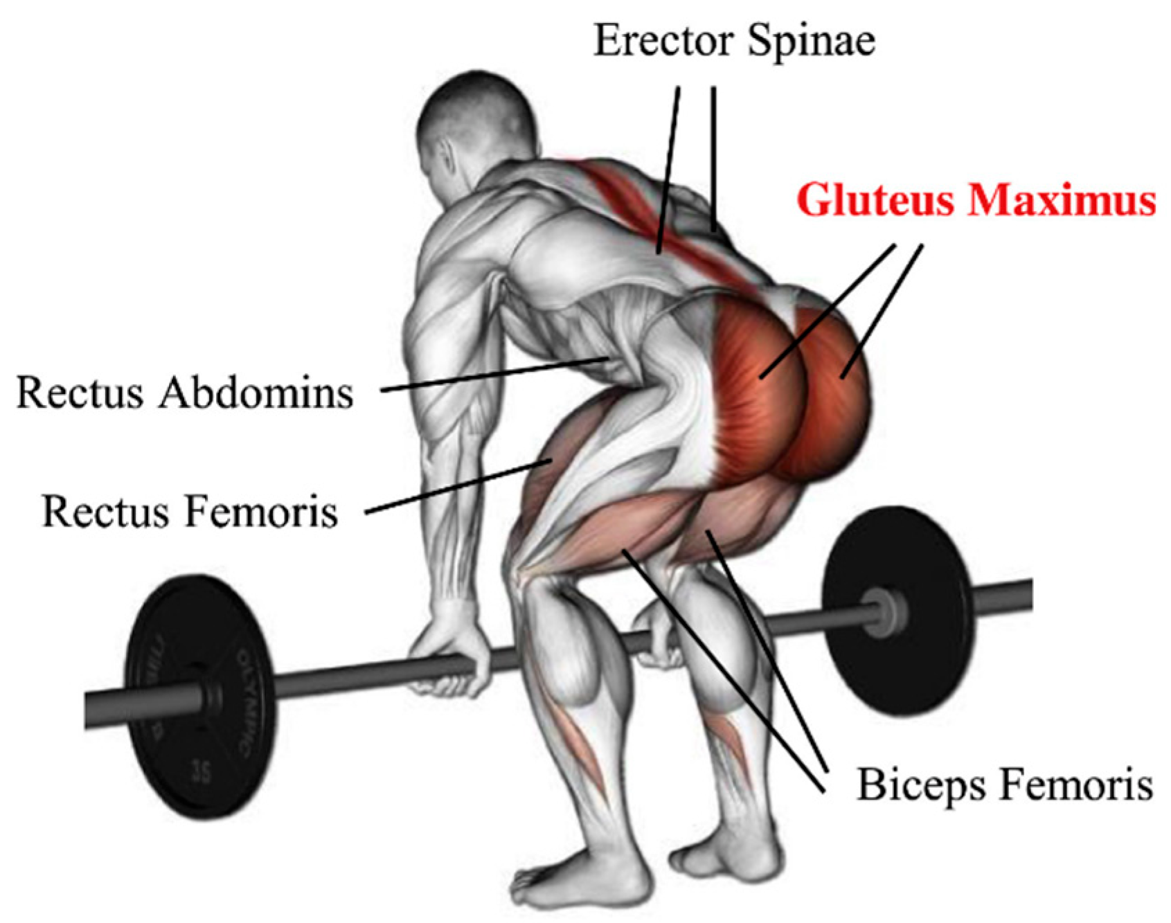
The hip joint can be considered as a ball and socket, which is enclosed with strong and steady muscles, allowing a wide range of movements in multiple physical planes and still being remarkably stable [
34]. The hip’s geometry allows rotational motion in every direction to maintain appropriate stability, requiring a high number of muscle controls originating from a broad surface area. There are 22 muscles in the hip joint operating to stabilize it and generate the force needed for the hip movements. The hip’s muscular anatomy is classified into adductor group muscles; inner and outer hip muscles [
35]. In terms of human anatomy, the Gluteus Maximus, situated on both hips, is the primary muscle involved in the waist and hip movement, as seen in
Figure 1 [
5,
34]. These two muscles operate as one synchronized muscle during waist flexion and extension due to the rotation orientation of both hip joints being the same during waist flexion and extension. This implies that an actuator on each hip joint might aid in waist motions. The muscle activity of thigh muscles is of interest when performing a squatting exercise [
36]. Notably, the quadriceps show more significant muscle activity than the hamstrings during the complete ascent phase [
29]. The focus is to relieve muscle groups of the burden of working concentrically and eccentrically to control the motion of the knee joint.
2.2. Biomechanical Analysis of Human Body during a Lifting Task
Biomechanical techniques have helped understand the loading conditions that cause lower back pain and the development of techniques for the prevention of musculoskeletal disorders in workers through force assistance for the lumbar spine during lifting tasks. The biomechanical study of the lumbar spine in postures related to lifting tasks is covered in this section. The scientific literature suggests approaches for estimating load and moment on lumbar spines based on either static and dynamic analyses that lead to a biomechanical model for loading the spine or via experimental measurements for the muscle activity during the lifting [
37].
The study here has adopted human kinematics and kinetics data from reference [
38] to determine the moment, power, and load assistance of the lumbar spine during the lifting task. Biomechanical data during squats were collected and analyzed by using a motion capture system, force plate sensors, and EMG sensors. During the lowering or lifting of the load via extension action, the peak requirements were recorded. Therefore, kinematics analysis is used to investigate the system’s motion. The torque and power required to lift a 15 kg load are 110 Nm and 310 W, respectively, with a speed of 2.6 rad/s for the hip joint. However, the actuator’s targeted assistance torque is almost 50% of the required torque to lift the load between 5 kg and 25 kg. Biomechanical data were used to verify the design of wearable assistive devices. In addition, the actuation’s required characteristics to be implemented on each joint were determined using joint torque data. Since the joint torque distribution varies within the semi-squat tasks. It is popular to design the actuators based on the peak torque values [
39].
The kinematic; degree of freedom (DOF), kinetic (joint torques), and range of motion (ROM) characteristics of lower limb biomechanics represent movements’ static characteristics. However, the lifting task is dynamic and is characterized by joint rotational speed and the frequency bandwidth of the movements [
39]. The frequency bandwidth of the hip joint’s human motion ranges from 4 Hz to 8 Hz [
40]. The actuator’s bandwidth should at least fulfill the frequency elements of human motion in order to respond rapidly to the control signal. Moreover, the actuators are designed analogously to the human muscles to mimic the human muscles’ function during lifting tasks [
41]. The design requirements that depend on biomechanical data are summarized in
Table 1.
2.3. Actuator Design Considerations
Figure 2 shows the conceptual design of ES-RSEA. This compliant actuator of a soft trunk–hip exoskeleton enables the design of a portable and lightweight system with higher torque delivery and further lumbar assistance while maintaining high compliance, safe human–robot interaction, and faster adaptation to human movements. The actuation unit ES-RESA includes a modular and a compact rotary SEA integrated with an energy storage unit. The RSEA provides mechanical compliance with a high torque-to-weight ratio at the interface between the exoskeleton and the user. On the other hand, the energy storage unit is proposed to provide additional torque based on the biomechanical energy conversion of the human lifting cycle. The uniqueness of the design concept combines a precise mechanical design of assistance timing with high robustness and repeatability.
The central concept for designing the lower limb exoskeleton is according to the anthropometric factors of the human body. The interaction between the human body and the exoskeleton is determined by whether the design is anthropomorphic or non-anthropomorphic [
42]. Moreover, the lumbar support exoskeleton design is based on the Malaysian population, and so the anthropometric data for Malaysian workers are collected according to reference [
43]. Therefore, the lumbar support exoskeleton is considered anthropomorphic, meaning that the pelvis and thigh components of the exoskeleton move similarly to their human equivalents.
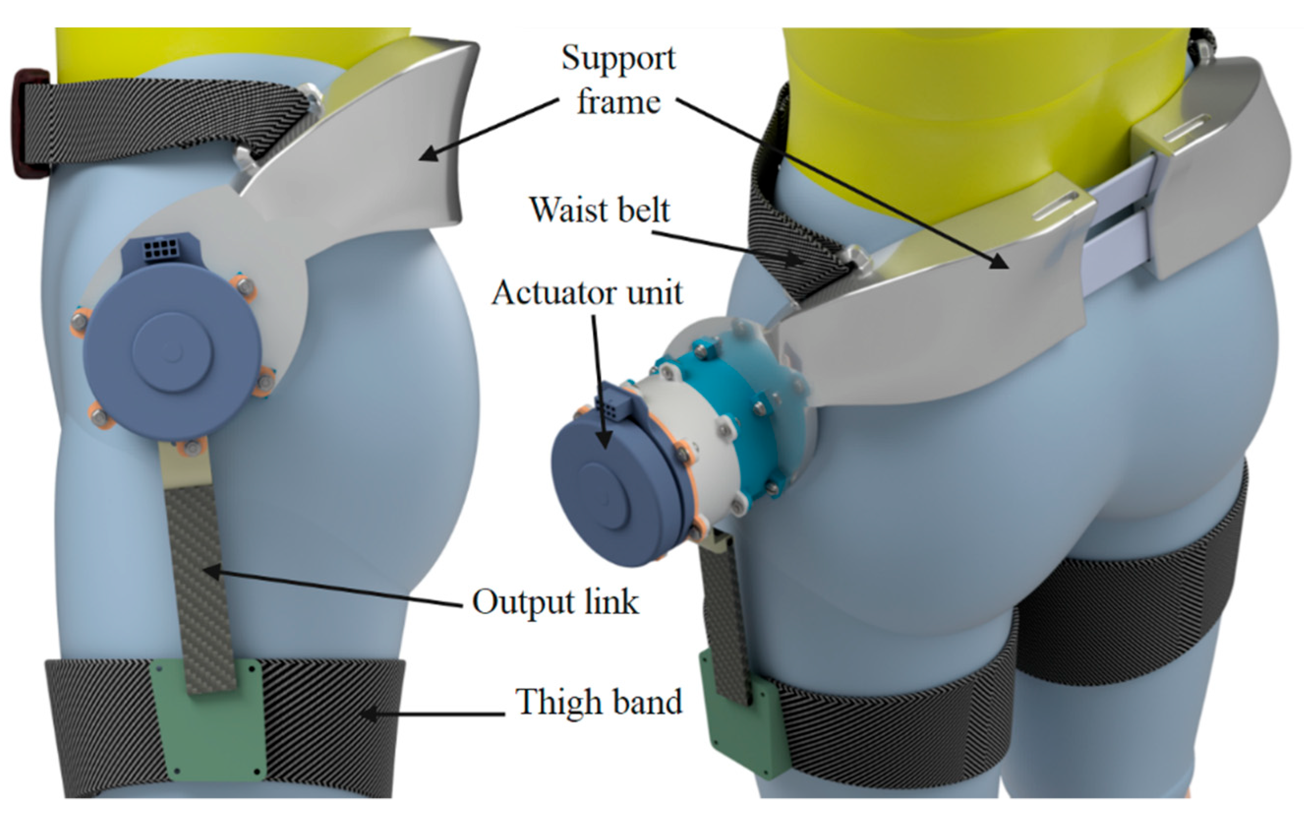
Figure 3 gives an overall perspective and a detailed view of the lumbar support exoskeleton worn on the human body.
The range of motion of the human joints forms a critical biomechanical factor of an exoskeleton. By analyzing human joints’ movements during the lifting tasks, the joints’ comfort angles have been defined, as shown in
Figure 3, to prevent any pain or even danger to humans during the lifting postures [
37]. Moreover, the ROM of the hip joint is sufficient to provide lifting tasks. Flexion/extension, adduction/abduction, and internal/external rotations are the three rotational DOF of the hip joint [
39]. The hip flexion/extension is the active actuated DOF of the proposed exoskeleton, whereas the other two DOF are passive.
Exoskeleton actuator design considerations also include a high output power-to-weight ratio as well as characteristics, such as high efficiency and bandwidth, low inertia, and fast response [
44]. One of the critical design factors for the SEA is the value of torsion spring stiffness, which characterizes the performance and features of the SEA. The torque measurement resolution is also influenced by the spring stiffness [
45]. Thus, a suitable stiffness value needs to be chosen to trade-off between the large torque bandwidth and high compliance. The literature analysis on optimum stiffness for SEA in wearable robotics applications has adopted different stiffness values ranging from 100 to 1500 Nm/rad [
46,
47,
48]. These optimum stiffness values have been estimated by theoretical analyses or even by simulation studies [
45], based on a trade-off between the various design criteria of SEA and the DC motor drive specification. Moreover, in this study, the proposed ES-RSEA has a low stiffness (approximately 450 Nm/rad) to improve compliance in the human–robot interaction with satisfied frequency bandwidth.
The novel part of ES-RSEA is the energy storage device. Since the spiral spring is the functional core of this device, the amount of potential energy relies mainly on the spring stiffness value. Typically, the spiral spring stiffness value K is determined carefully to ensure that the stiffness is not too rigid; otherwise, it causes over-resistance against human movement or even discomfort. Moreover, the stiffness should be softer to ensure that the spring will not adversely impact the DC motor performance during the ascent phase of the lifting task. Therefore, the spiral spring designed for the lumbar support exoskeleton required spring constant K = 10 Nm/rad, maximum deflection θ where the spring can reach 120 degrees, and a maximum spring torque Tmax of 20.94 Nm.
3. Mechanical Structure Design and Working Principle
The biomechanical principles of human lower limbs were adopted to design a lumbar support exoskeleton with a storage technique. The human squat lift reveals that in the cycle of lower limb descent and ascent, gravity energy is related to lumbar descent; the human body’s weight causes a human hip joint to exert negative work. Consider that an additional mechanism device is utilized in the deceleration phase to absorb the kinetic energy of the lower limb and transform it into potential energy, and temporarily store it for the next acceleration phase of the limb joint. In that case, it may even strengthen the human body’s energy performance.
The lumbar support exoskeleton consists of three parts: the energy storage element, the series elastic actuator, and a flexible wearable structure. The exoskeleton’s support frame is placed around the human centroid at the human waist to reduce the extra metabolic potential for the wearer, as shown in
Figure 3. Simultaneously, the output link of the actuation system is attached to the upper part of the thigh. The actuation system, located on the hip joint, is integrated with the energy storage and the series elastic actuator. Since the spiral spring is selected as the core for the energy storage unit, the spiral spring design can maximize the spring features to extract as much potential energy as possible without ignoring the human comfort factor.
Figure 3 presents the overall view of the lumbar support exoskeleton worn on a human body along with the designed actuator and a detailed view of its structure.
3.1. Mechanical Design of ES-RSEA
3.1.1. Configuration
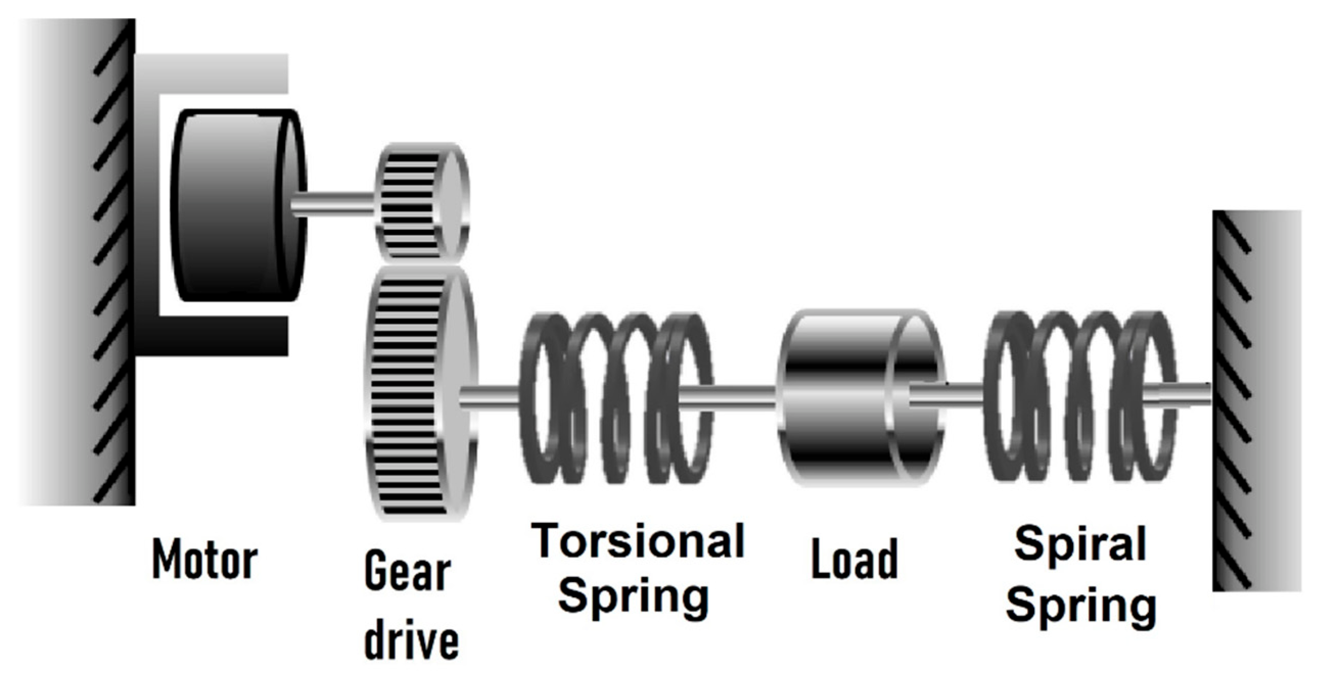
The conventional SEA combines a motor, a transmission drive, a spring, and an output load so that the spring can directly sense the force from the output load [
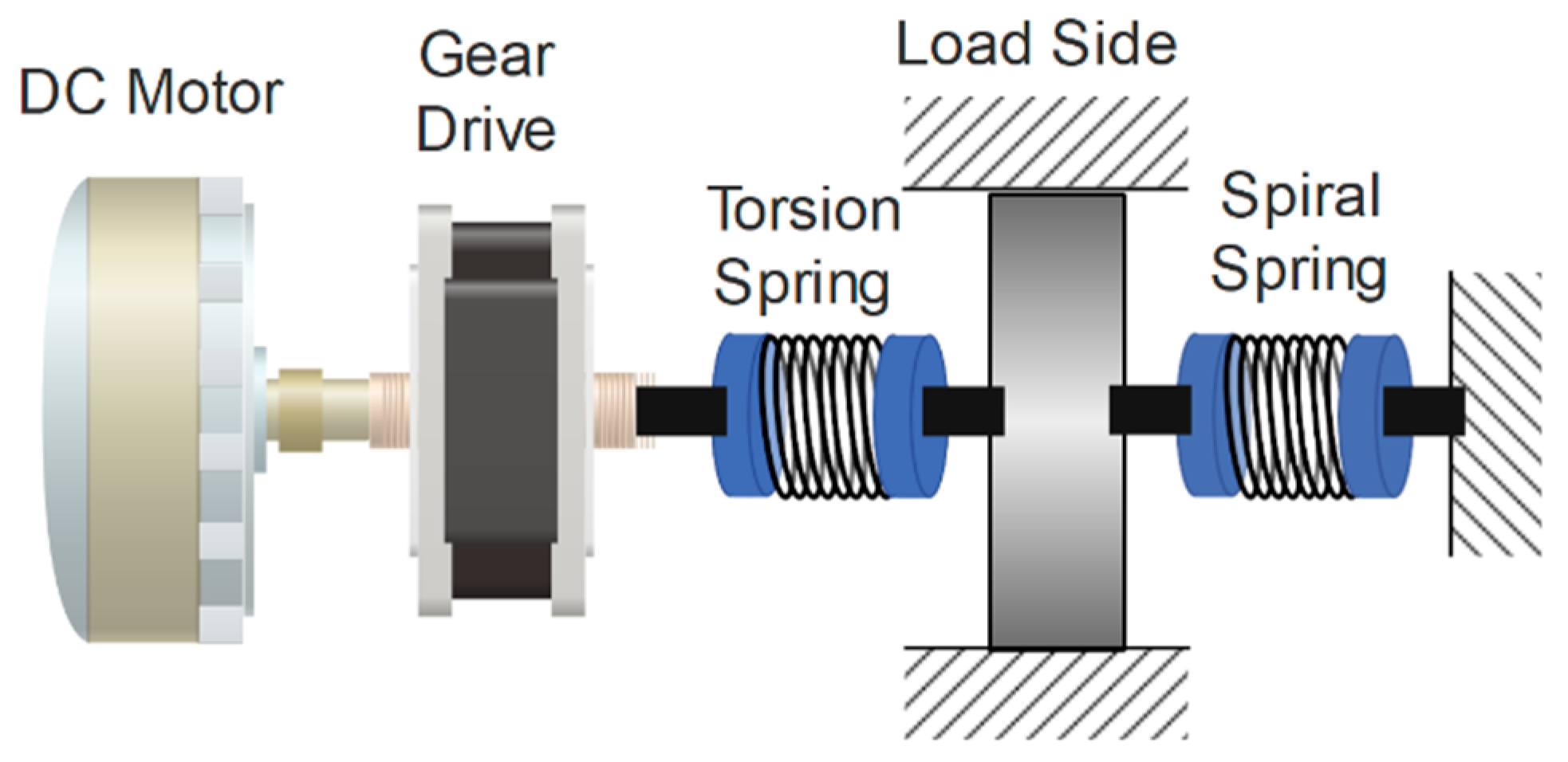
49]. This configuration has been adopted in many SEA designs since the first SEA was proposed. However, the proposed ES-RSEA actuator is designed with a modified version of the conventional configuration by integrating the spiral spring into the actuator’s second spring. The end of the spiral spring is attached to the output load, and the other end is fixed to the ground. The ES-RSEA configuration is illustrated in
Figure 4, where the spiral spring is utilized to store and release energy, and the torsional spring is used as a compliant element. Moreover, the motor stator is fixed to the ground to efficiently transmit the torque. The gear drive amplifies the torque, so the spring’s deformation can transmit the output torque. The actuator’s output torque can be calculated depending on the spring deformation measurements [
50]. Therefore, the spring deformation must be measured by two encoders: the motor angle and the load side angle.
3.1.2. Mechanical Components
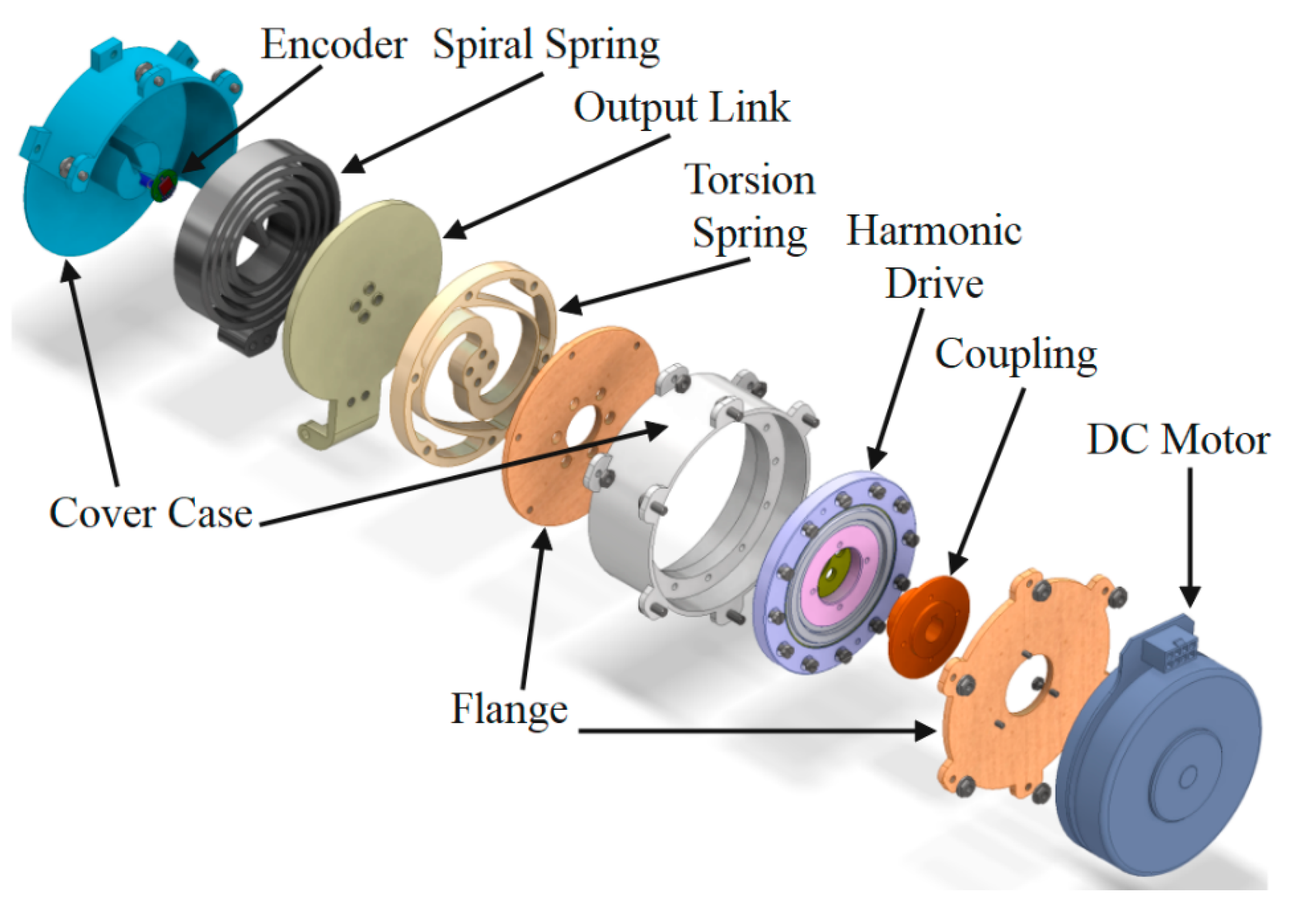
Considering the requirements mentioned for the actuation system, the ES-RSEA actuator was selected accordingly. The actuator is driven by a flat DC brushless motor (EC90, 24 V, 160 W, Maxon Motor, Sachseln, Switzerland) embedded with a MILE encoder (1024 Cpt). A very compact design is made possible by the DC motor in conjunction with a 100:1 Harmonic Drive (CSD-25-100-2A-GR, Harmonic Drive
®, Limburg, Germany). The Harmonic Drive is connected to the custom-made planner torsional spring, which is attached to the output link-circular disc. The torque is transmitted to the hip joint through a circular disc with an output link connected to the thigh by a bandage and baffle to the human leg. An RMB14 angular magnetic encoder (absolute-12 bit-RLS) is mounted on the ground, while its magnet is placed on the axis output link-circular disc to measure the actual output angle. The encoder’s cable is passed through a small hole drilled into the inner cylinder to protect the cables from any damage, as shown in
Figure 5. A custom-made spiral spring is connected to the output link-circular disc on one side, and the other side is fixed to the actuator’s case cover. Finally, the cover case of the actuator consists of two main cylindrical parts with two connecting flanges. These parts are assembled by a few bolts and nuts, which enable portability and compatibility for the proposed actuation system. The cover case with a deep sky-blue color has been designed in shape to provide mechanical brakes for the output link within the designed working motion range for the hip joint during squatting. This mechanical brake will protect the human from any motion that exceeds the human safety range of hip movements.
The selected parameters of the ES-RSEA actuator are shown in
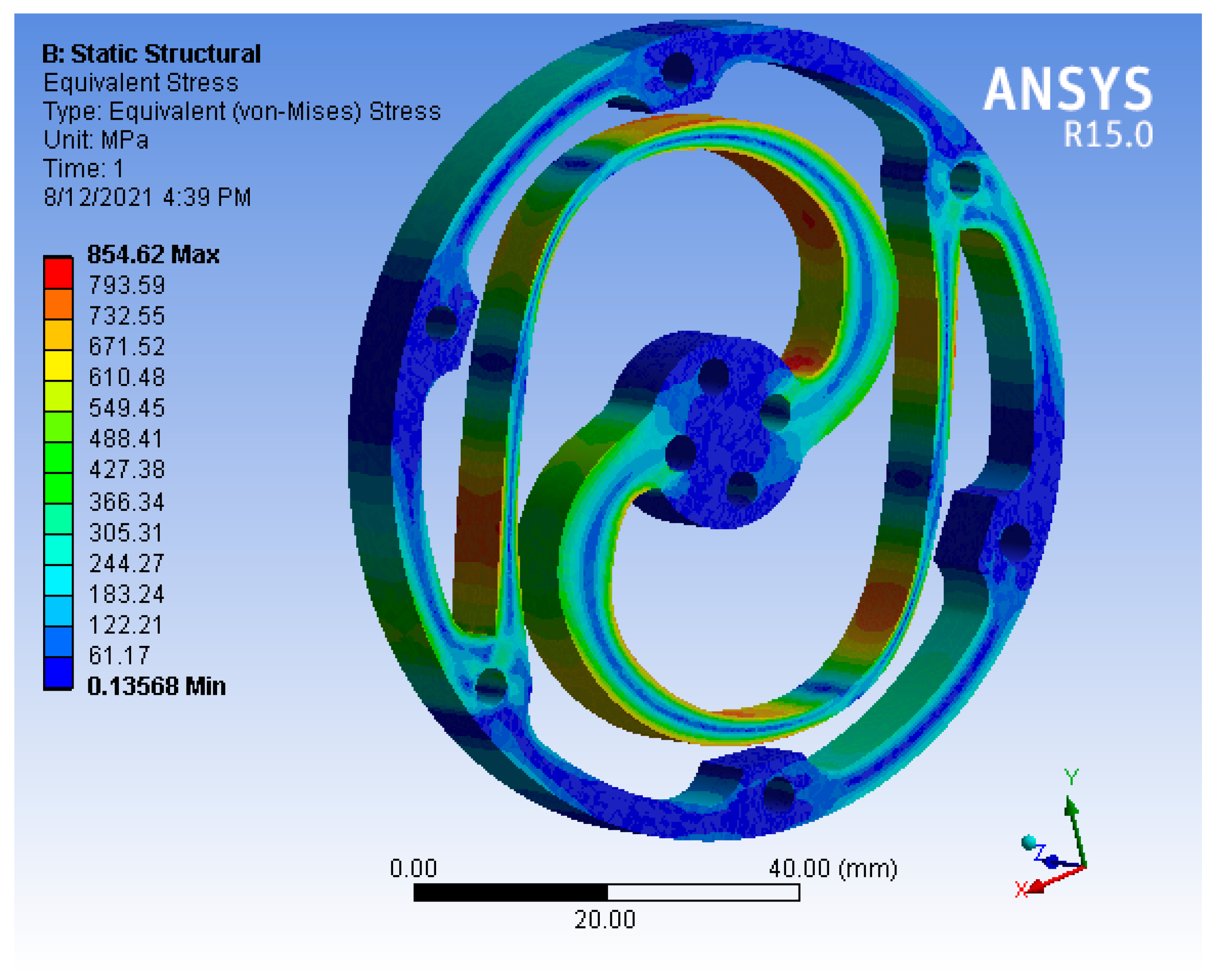
Table 2. The torsional and spiral springs were designed and optimized to reduce weight and size while maintaining the required spring stiffness and spring deformation. The torsional spring was designed and optimized using the finite element method (FEM), Ansys Workbench 15.0 software, and CAD models were obtained using Autodesk Inventor, as shown in
Figure 6. The maximum output torque of 45.7 Nm and the 450 Nm/rad stiffness of the torsional spring were considered desirable values of the actuator design based on actuator design considerations mentioned in
Section 2.3. Furthermore, the spiral spring was designed based on the fundamental spring design Equations. Then spring design parameters were optimized to fulfill the purpose of the energy storage device in the ES-RSEA design, as illustrated further in the next section.
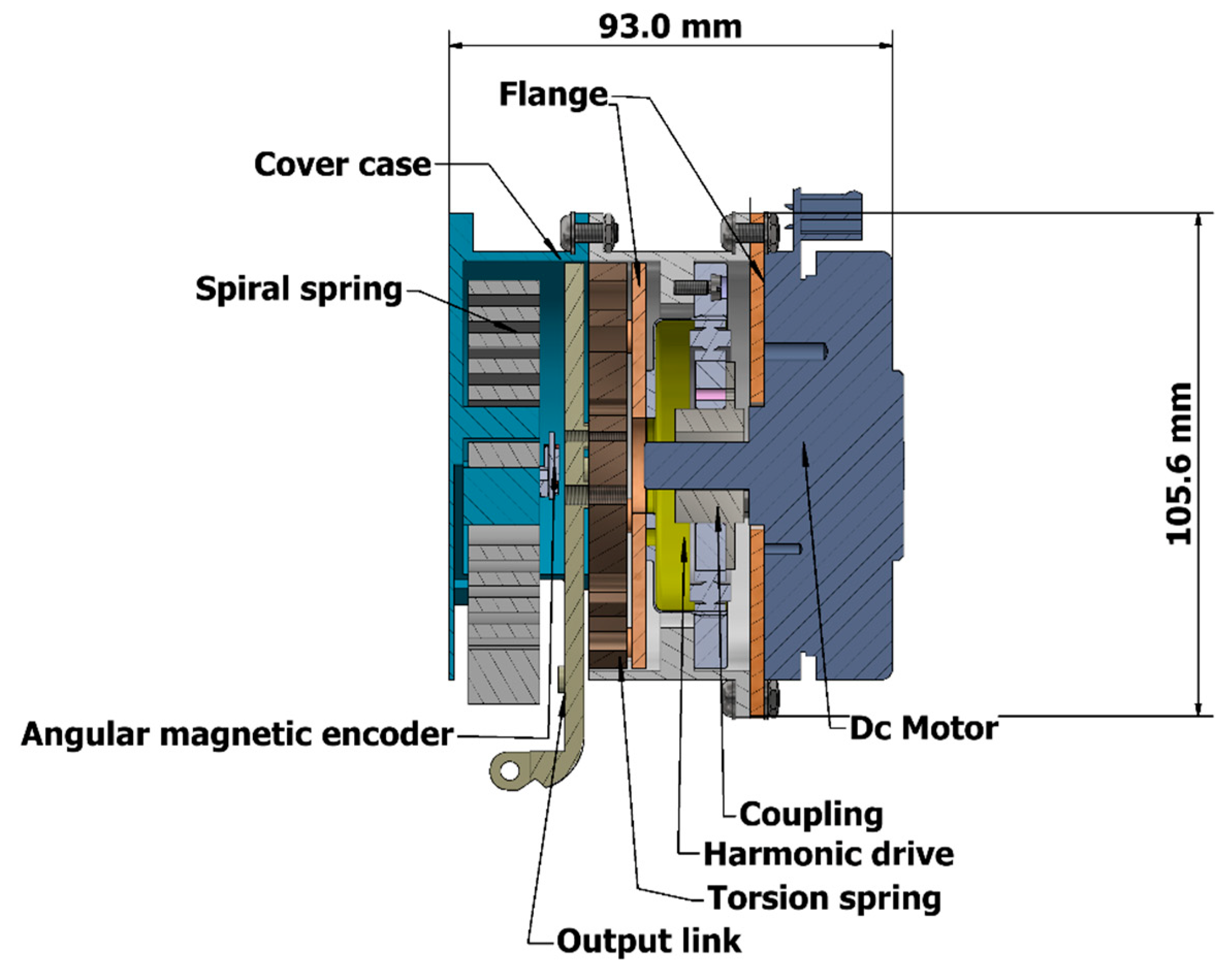
Figure 7 illustrates the cross-section of the ES-RSEA actuator. Since all the actuator parts are assembled in a compact design, the radial length of the actuator is 93 mm. The ES-RSEA actuator is mounted on the waist of the human body, particularly on the hip joint. The cover case in deep sky-blue is fixed to the robotic structure by bolts and nuts, as shown in
Figure 7.
3.2. Mechanical Design of Energy Storage Device (ES)
The passive elastic element used for the energy storage device is the spiral spring. Among other types of spring, the spiral spring has excellent features for storing and releasing energy for an extensive range of deformation or angular positions. Since the range of hip joint motion during lifting demands is around 120 degrees, the spiral spring would be the most suitable spring for this role. Because of its stiffness, a spiral spring will always try to return to its original shape; it can generate the opposite torque to gravity, resulting in the minimum torque required for the hip joint. The arbor end of the spiral spring is fixed, and the torque is applied at the spring’s outer radial. The torque applied bends the elastic deformation on the spiral spring strip, causing the spiral spring to rotate around its axis, storing and releasing elastic energy. It is designed to absorb and store the biomechanical energy distributed at the hip joints during the descent phase of a squatting cycle and then release it in the ascent phase. The energy stored is released from the outer end, transmitting to the thigh part by the output link of actuation attached to the spring. This passive element generates an energy-free system because no external power source is involved in the motion.
3.2.1. Design Fundamentals of the Spiral Spring
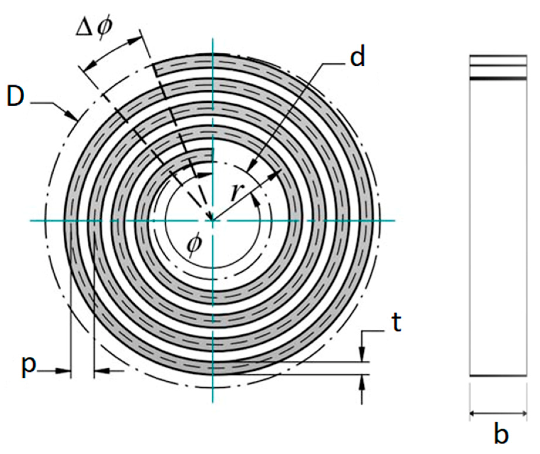
Spiral springs are the most suitable storage elements for electromechanical actuation configurations to preserve the high potential energy intrinsic to the human hip movement. The spring design is usually made from a flat rectangular strip of raw metal and wraps towards the outside of the mounting spiral spring. The torques are applied tangent to the outer ring of the spring while the inner arbor is fixed, and the angular variation between these extremities can determine the spring compliance. Additionally, springs could be coiled with a pitch P, the radial gap between coils, preventing coil interaction during spring compression. Friction losses do not exist since the coils are usually not in contact with one another. Spiral springs, as a result, have a linear torque-deflection relationship. However, since stocks of spiral springs are rarely available, they are usually manufactured to customized requirements [
51].
The length L, width b, pitch P, and arm thickness t of the rectangular wound stripe are required for manufacturing spiral springs. The spiral spring design Equations are taken from the handbook of spring design [
52]. The geometry of a spiral spring is illustrated in
Figure 8.
The maximum allowed stress,
, which is not higher than the material’s cyclic fatigue strength, can be obtained from the deflecting beam formula:
The maximum spring torque, is related to maximum angular deflection and spring stiffness . Hooke’s law describes torque exerted by a spring being deformed, which is defined by .
Additionally, the length of strip material is computed from:
Which depends on a cross-section of the strip, the material’s elastic modulus E, and the stiffness value of the spring .
While the arbor diameter d is usually defined first, the minimum allowed outer diameter D is studied to prevent a tight warp-up spring on the arbor before achieving the desired deflection, which can be calculated as:
For the spring geometry design, the spiral arm shape is defined based on the Archimedean spiral and is characterized in polar coordinates (r,
) described by:
The spiral angle and radial distance r at a given angle are the factors that shape the spiral arm, while the coefficients a and b are, respectively, calculated via Equations (5) and (6) where denotes the spring’s total wrap angle.
Additionally, the spiral arc length
equals the length of the strip in Equation (2), computed as
The type of designed spring is called a brush spring. These types of springs are often deflected less than 360 degrees and are generally subjected to the following design requirements.
Length-to thickness ratio L/t should be between 200 and 1000.
Width-to-thickness ratio b/t should be within a range of 3:1 to 15:1.
The allowable stress should not exceed 1000 MPa.
Grade 304 stainless steel was selected as the spring material due to its low cost as a material and ease of manufacture with excellent yield strength. Design for manufacturing (DFM) is considered an essential factor for designing spiral springs. In this study, the cutting machine technology that used water jet cutting exposes spiral spring geometry dimensions to several design constraints. The material 304 stainless steel plate is widely available with a specific width range of 8, 10, 12, and 15 mm. The waterjet cutting stream’s width (nozzle size) determines the minimum value of (P-t) to 2 mm. The pitch P is the space between the spiral arms that a waterjet cutting stream can efficiently cut. It also enables the coils to wind freely until the specified load is reached. In addition, the arm thickness should not be less than 2.5 mm to avoid any material failure and increase the bearing stress for the torque load.
Furthermore, the spiral spring element is deeply integrated with the proposed actuation layout, so the spiral spring’s design mechanism should be compatible with the actuator parts. The arbor diameter d was selected as 30 mm, and grounded in the actuator’s case; the maximum outside diameter D was chosen at 80 mm, and attached to the actuator’s output link.
3.2.2. Design of Spiral Spring
The design procedure to accomplish a suitable and optimal spring width b, arm thickness t, and pitch P depends on the design requirements and allowable range of spring parameters mentioned in the previous section. This design method can lead to an efficient spiral spring design for a proposed energy storage device. The first design step is to find all possible range values of t and P with a given thickness b, which would not exceed the allowable stress of the material.
Figure 9 shows the spring parameters thus required, where each point in the painted surface represents a feasible range of spring parameters (t and P with b). Secondly, since the minimum allowable value for (P-t) is 2 mm, it is rational to remove all points from the painted surface that do not meet this condition. The resulting points are shown on the painted surface in
Figure 9 with a dark color.
The fatigue strength of wide and thin springs is higher, but at the cost of increased total volume and weight of the spring. It appears from the dark colored surface in
Figure 9, that the feasible range of material width b is narrowed, whether 15 or 12. Thus, the optimum design parameters at width 12 and 15 are denoted in
Figure 9 as A and B, respectively.
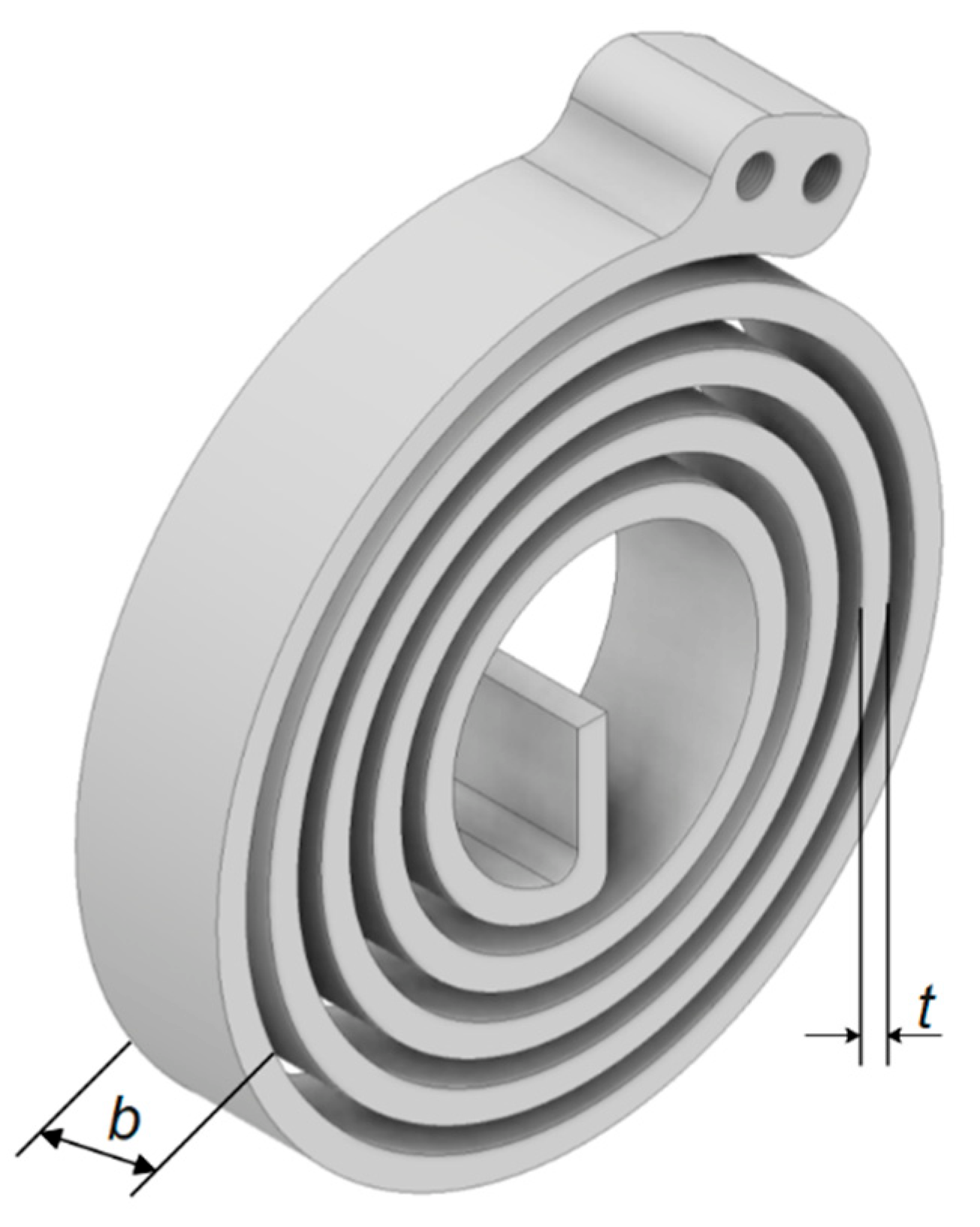
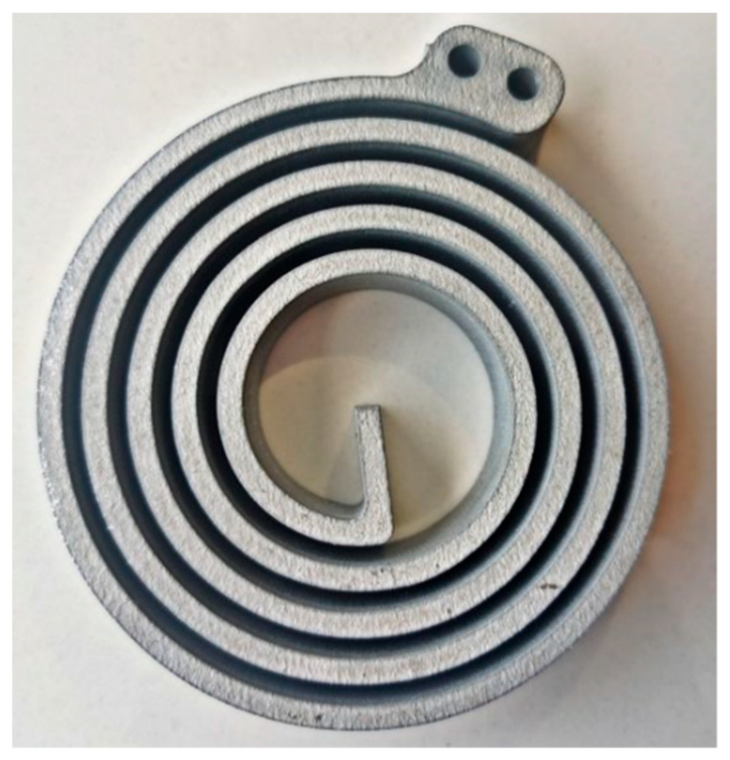
Table 3 shows the spring design parameters of the optimum design of A and B. As a compromise, a spring, denoted as B, with t = 3.1 mm, b = 15 mm, and P−t = 2.7 mm, was chosen. It was considered short enough to fit within the compact actuator, while maintaining good fatigue strength. Its maximum stress σ is 871 MPa, which is much lower than the allowable material stress. The CAD for the designed spiral spring based on the obtained geometry design is shown in
Figure 10.
3.3. Working Principle
The mechanical structure of the energy storage-rotary series elastic actuator (ES-RSEA) is shown in
Figure 5. The assistance torque of ES-RSEA is generated by the DC motor and energy storage device. The torque generated by the energy storage device can be in two phases. In the descent phase, the assistance torque is generated by the compression of the spiral spring. The spiral spring is fixed from the inner end to the cover case while the outer end rotates synchronously with the attached leg through the output link. The proposed design of the energy storage device implemented with SEA enables the spiral spring to rotate based on the motion range of the hip joint. On the other hand, the assistance torque of the ascent phase is generated by the release of the stored energy in the spiral spring. The direction of this assistance torque will be the opposite of the first phase. In the ascent phase, the torque assistance of the DC motor is combined with the released torque of the spiral spring. The DC motor generates continuous torque due to the torque reference command. Subsequently, the harmonic drive reduces the speed (the speed output is less than the speed input). Since torque output will be the inverse of the speed function, output torque will increase due to the drive ratio of harmonic drive (drive reduction = 100). After the harmonic drive, the torque is transmitted to the output link through a torsion spring. The torsion spring, as a compliant element, will provide stiffness and flexibility along with torque transmission to the output link. Finally, the output link is driven by the DC motor and associated with the movement of the hip angle. At the same time, the release torque of the storage device will rotate the output link in the same direction. Therefore, the output assistance torque in this stage is a combination of the two output torques.
4. Energy Flow and Semi-Squat Lifting Strategy
The energy storage device largely depends on the human body’s dynamic movement. During the squat lifting process, the muscles absorb human bioenergy dissipated at the biological hip joint. Nevertheless, while the activation muscles need to exert negative work to stand against the hip joint movement, a proportion of these muscle functions can be substituted, and the consumption of energy in muscles might be reduced by transferring the kinetic energy of hip joints to the storage element of the exoskeleton’s actuation system, where it is transformed to elastic potential energy. If, subsequently, the hip joint needs to be driven by positive work from muscles, the exoskeleton’s storage element, particularly the spiral spring, can release a portion of the energy stored and transformed it to kinetic energy to assist the hip joint movement. This conversion of energy assists the muscles and the human body in reducing energy consumption. However, elastic energy, which has relatively inexpensive, renewable, and emission-free properties, is among physical-mechanical energy storage. Additionally, one of the proposed alternatives to subdue the power constraints is elastic energy, which provide a sustainable source of energy to power the dynamic movement of the exoskeleton [
32].
Since the human body governs the hip joint to consume much negative work during the squat lift in the lowering phase, especially when lifting loads, pathological changes and shrinkage will occur in the hip joint. A fraction of this energy may be captured by the exoskeleton through the energy storage device. The stored energy can be released for assistance once the hip joint requires positive work during the lifting phase. Furthermore, the power fluctuation is varied significantly and synchronously between positive and negative work during the phases of semi-squat lifting, making energy storage and release for the hip joint sufficient. Accordingly, the hip joint needs more positive power and may also exert negative power steadily in the squat lifting cycle [
32].
Based on the analysis of the human body’s energy distribution and biomechanics during lifting tasks, the storage element integrated into the actuation system is installed at the human body’s hip joint. First and foremost, during the lifting tasks, the hip joint has the most extensive range of joint motion. For this reason, the hip joint has been chosen rather than the knee and ankle joints; the extensive range of hip joint motion indicates that it can provide sufficient and high energy storage. Consequently, the actuation mechanism does not interact but has the most wearable daily activity for workers during the manual handling tasks.
4.1. Lifting Strategy for Descent and the Ascent Phase
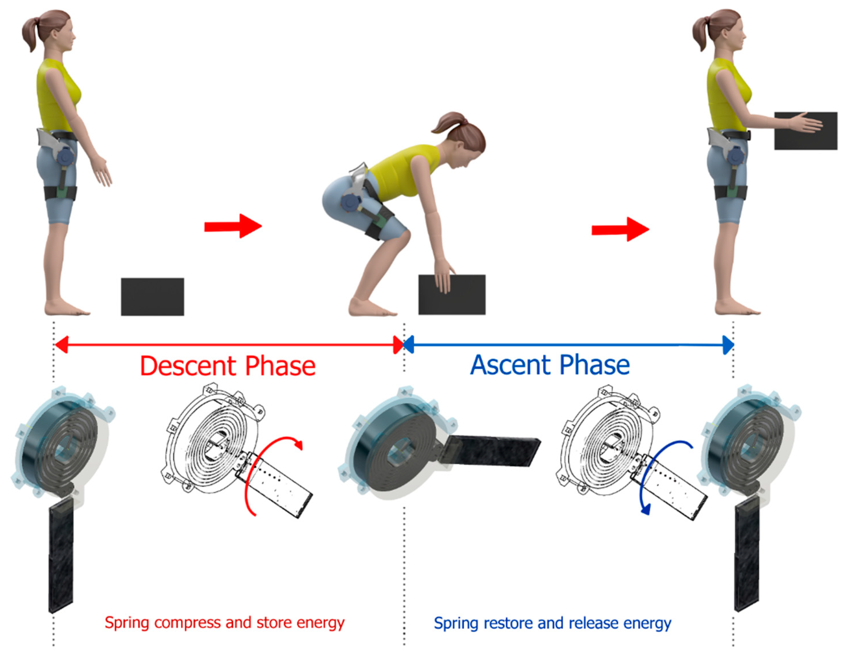
The power and torque assistance for the proposed lumbar support exoskeleton depend mainly on the delivery of assistance from the actuation system; SEA is integrated with the energy storage element. In other words, the performance and operation setting of the spiral spring and DC motor determine the lifting strategy during the descent phase, and ascent phase of the squat cycle, as shown in
Figure 11 with the working principle of the storage device during each phase. Each phase adopts a different function strategy between active and passive actuation of the DC motor and spiral spring, respectively. Moreover, the proposed lifting strategy provides several benefits related to assistance percentage, battery consumption for motors, and biomechanics employment.
Firstly, the descent phase is the first step of squat needed to pick up a load from the ground. During this phase, the type of assistance required is to hold and resist the inertia of a human body against its movement. Therefore, the spiral spring is employed to store the energy produced by human weight impact, applying torsional torque on the spiral spring till it reaches a fully compressed state at the end of the phase. The spiral spring serves as a passive device and provides resistance torque opposite to human gravity. Since the resistance torque principally depends on the value of the spring stiffness, the stiffness is chosen to provide sufficient resistance but not to exceed the human comfort limits. In addition, the spiral spring storage and compliance of the SEA prevent the adverse impact of human gravity on the DC motor. Furthermore, the DC motor is not powered during the whole descent phase. Thus, there is no battery consumption during the descent phase, which lengthens the overall battery life of the exoskeleton device.
The ascent phase of lifting squat demands significant assistance for lifting the loads. Only in this phase does the human receive two assistance sources synchronously, namely the output torque of SEA and the released energy of the spiral spring. The DC motor is powered and runs in the same direction as human movement to exert positive work. Simultaneously, the spiral spring starts to release its energy and torque stored during the descent phase. Since the released torque of the spiral spring and the SEA output torque are oriented toward the same direction, there is no energy loss between the output of the SEA and the spring. Consequently, the two assistance torques collaborate with one another. Thus, the proposed actuation mechanism would provide a higher level of assistance compared to sole DC motor.
4.2. Energy Storage and Delivery
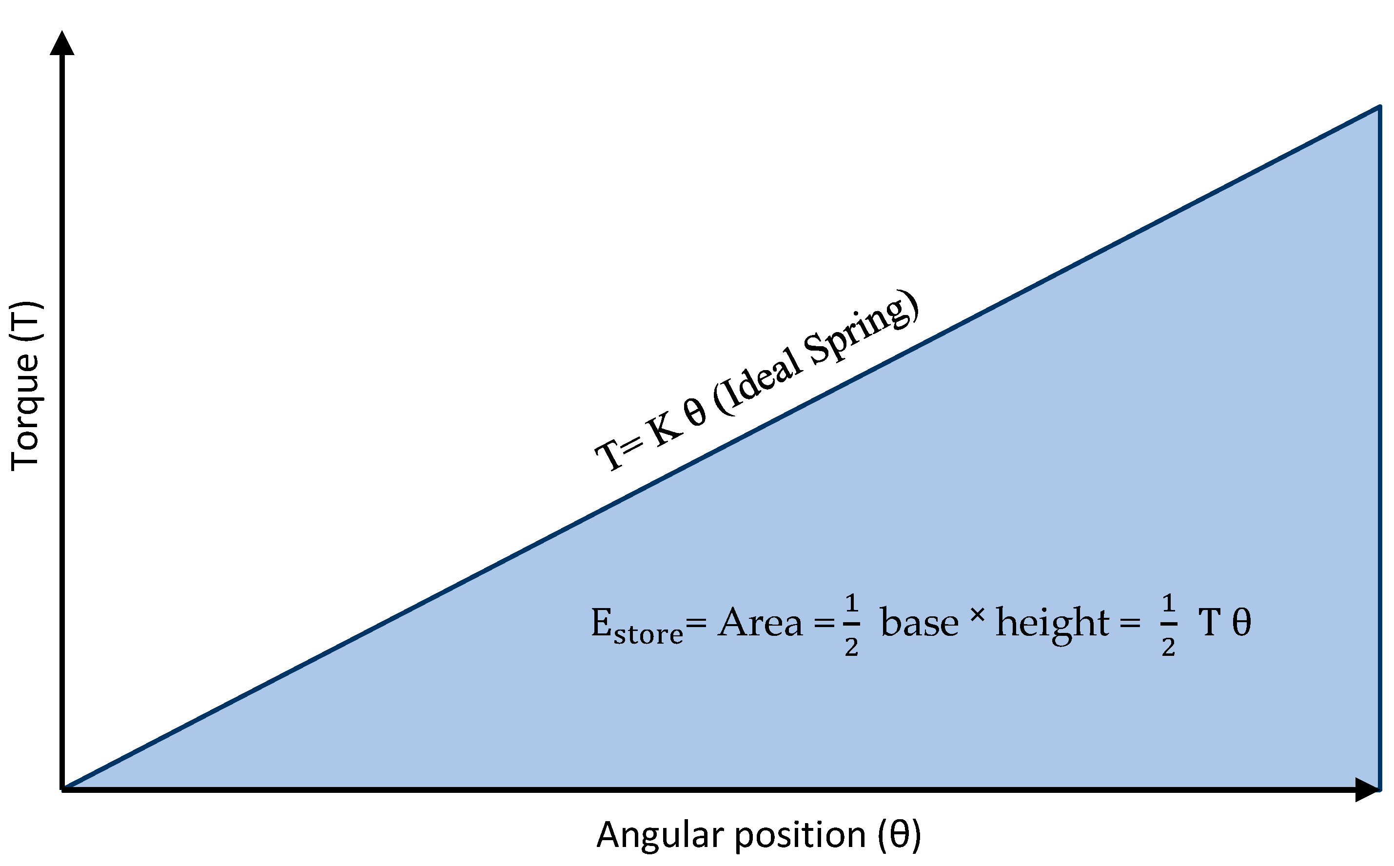
Elastic potential energy is energy stored as a result of applying a torque to deform the spiral spring. The proposed spiral spring can store the energy until the angular deformation reaches its designed limit and then springs back to its original shape, exerting work in each process. This exerted work can be used for driving and rotating the hip joint and generates torque assistance. Spiral springs designed to store elastic potential energy will typically depend on the stiffness value and maximum angular deformation. The spiral spring’s stiffness curve, also known as the characteristic curve, defines the relationship between the torque
and angular position
. A designed spiral spring’s primary behavior is the linear characteristic curve, since the spring is coiled firmly and no energy is lost in an ideal spring, as illustrated in
Figure 12. The torque-angular position relation is formed on Hooke’s law formula which is defined by
. In addition, the elastic energy storage can be calculated from the work conducted by the spring, representing the area under the torque-angular deformation curve in
Figure 12, and is given by
, or
[
53].
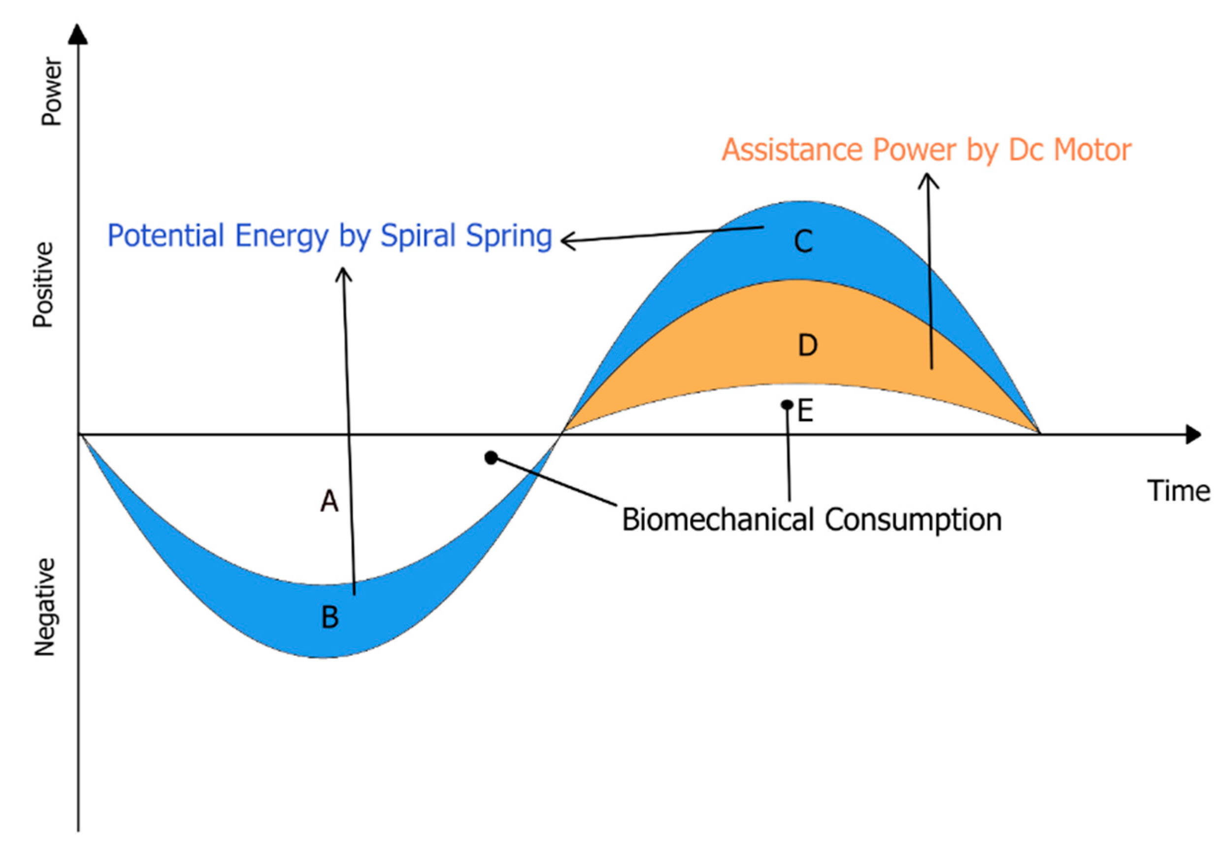
The variation in the human biomechanical power of the hip joint during semi-squat lifting besides using ES-RSEA is illustrated in
Figure 13. It shows an overall trend of hip biomechanical power over time, based on lowering and lifting scenarios. During the lifting cycle, the lower limb muscles performing on the hip joint generate significant negative and positive work, using a substantial amount of biomechanical energy. The lower limb muscles acting on the hip joint produce negative and positive work during the lifting task, which thus consumes a large amount of biomechanical energy. In the descent phase, the muscles around the hip joint mainly produce negative work for deceleration, representing areas A and B in
Figure 13. However, in the ascent phase, the positive work is generated to accelerate the hip joint and reduce the impact of the gravity, considering areas C, D, and E in
Figure 13.
The biomechanical energy and hip joint torque will be redistributed while the human body performs a lifting task with the energy storage device. In the descent phase, the hip movement rotates the energy storage device; the spiral spring generates resistive torque to support hip joint deceleration. The lower limb muscles are meant to execute this role of deceleration fully; nevertheless, the spiral spring performs the same job and decreases the hip joint’s negative effort. The spiral spring stores kinetic energy, as shown in
Figure 13 (area B). The next ascent phase begins after that. Although the hip muscles must accelerate the hip joint, the spiral spring’s potential energy is now directed to mechanical motion or torque to support the hip muscle (area C). At the same time, the DC motor of SEA generates assistive power
Figure 13 (area D). Consequently, during this phase, the positive work of the hip joint is minimized. The hip joint’s biomechanical work is redistributed with the aid of the merged energy storage from SEA, with the overall metabolic energy diminished, as described in
Figure 13 (area E).
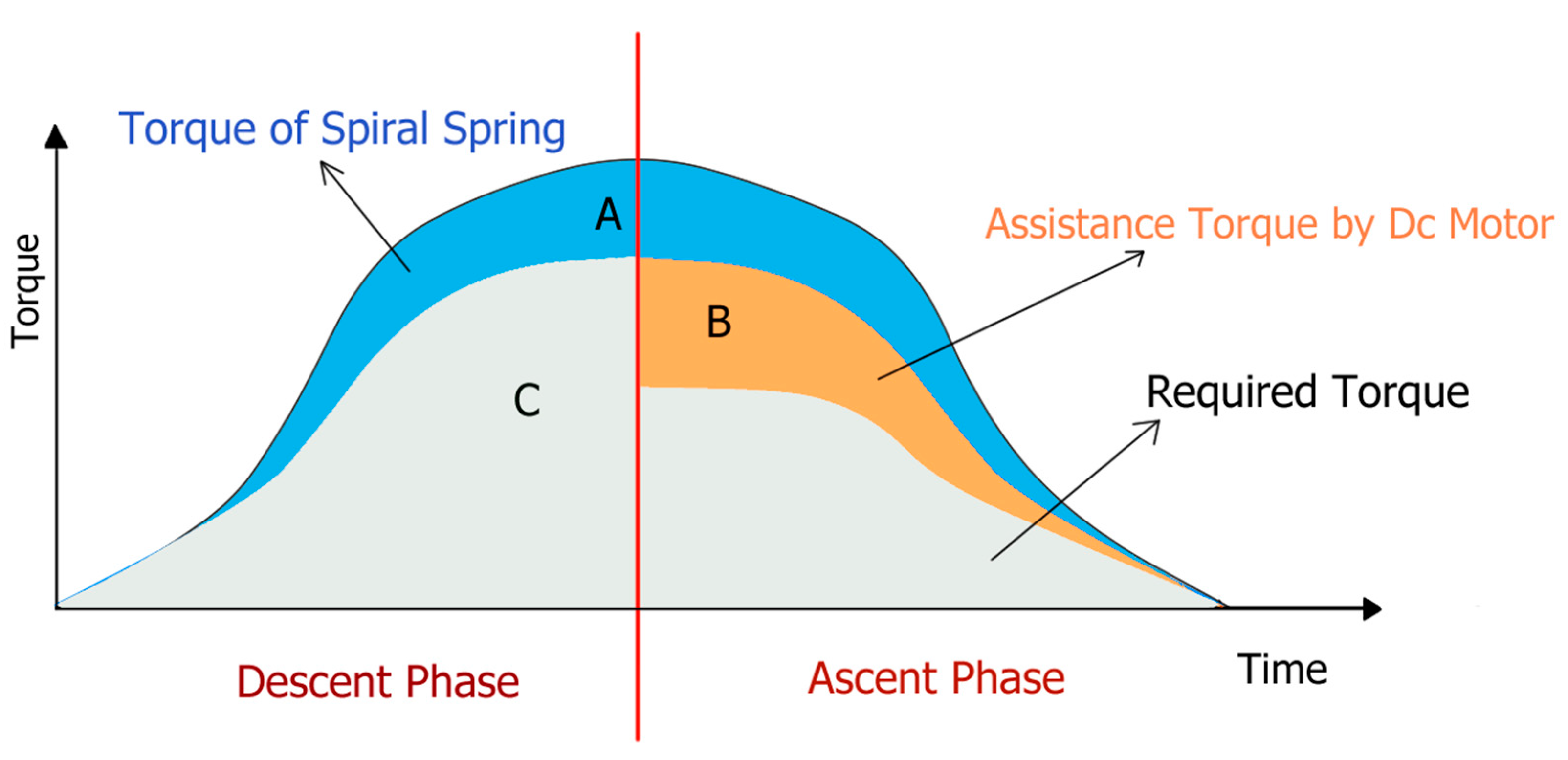
The theoretical torque requirement profile of the human body during the lifting task is shown in
Figure 14. During the first phase, the torque resistance is generated by a spiral spring to assist the hip joint (area A). The torque required for the hip joint is reduced (area C). Later, the ascent phase experiences significant assistive torque through a combination of the assistance torque of the DC motor and the released torque of the spiral spring, as shown in areas A and B. As a result, the required torque profile over the entire period is significantly reduced. Furthermore, the hip muscle force also reduces, empowering the user to lift the load.
7. Conclusions and Suggestions for Future Work
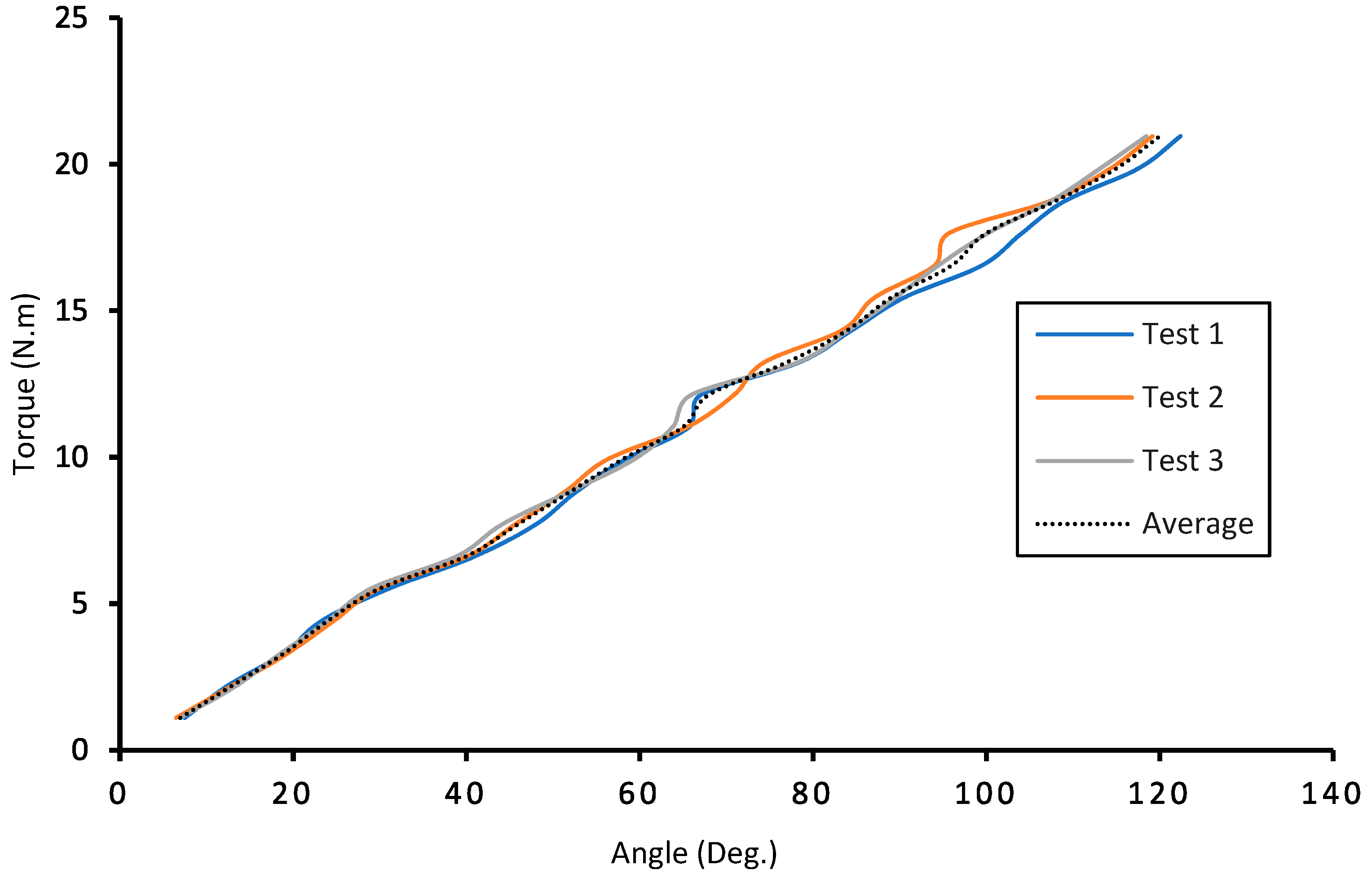
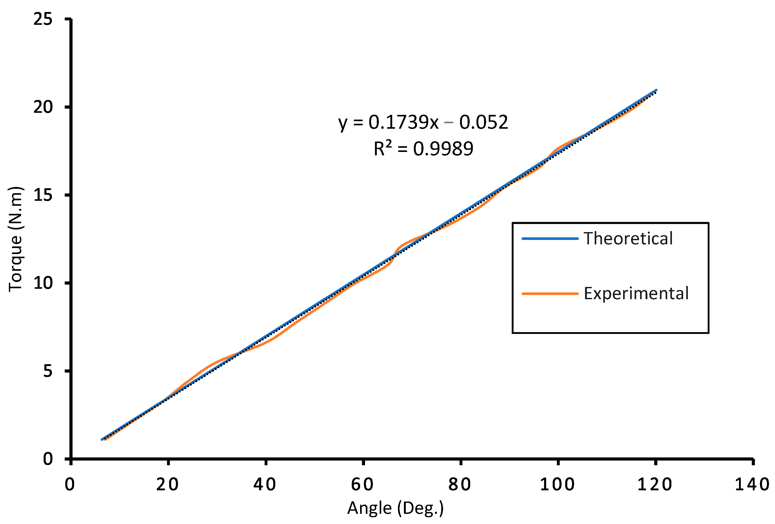
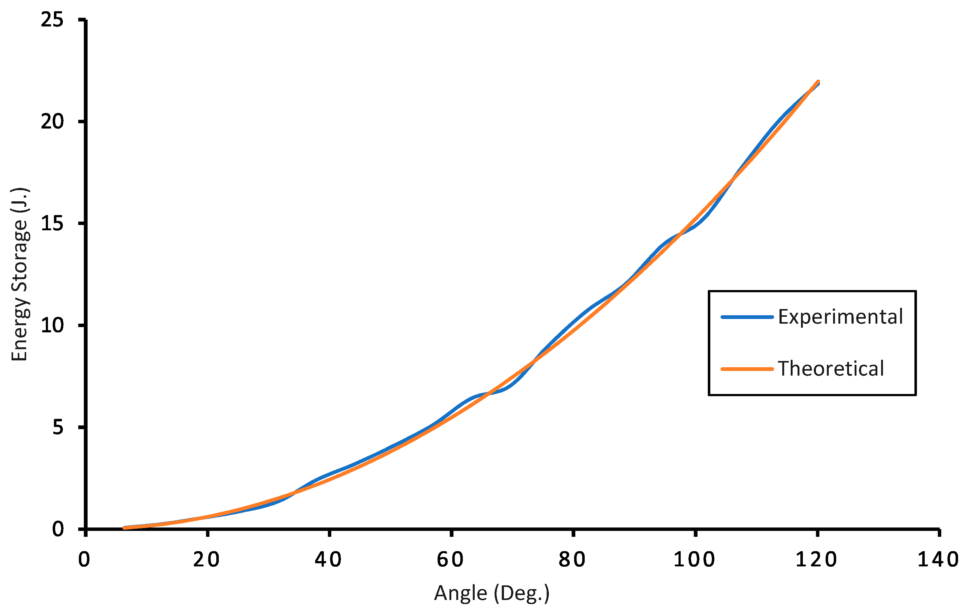
This article offers a supplement lifting solution for workers to improve their lifting abilities while performing manual lifting handling tasks. The structural design and prototype machining test of the spiral spring have been established and tested. The results revealed that the stiffness of the spiral spring is quite uniform and linear with significant storage energy. The ES-RSEA for the lumbar support exoskeleton has generated assistive output torque in both descent and ascent phases. The RSEA provided mechanical compliance with output torque at the interface between the exoskeleton and the user. At the same time, an energy storage (ES) unit utilized the negative work of lower limbs and satisfied the need for the external energy during the descent phase. The characteristics of the spiral spring has been efficiently featured as the primary element of energy storage unit, and it plays a vital role in providing additional torque to the overall actuator output. This spiral spring stored mechanical energy when the wearer bends forward and lowers the body to lift the load, where the kinetic energy of the lower limb was converted into potential energy. Subsequently, this stored energy in the mechanical spring can be released at the start of lifting an object to assist the acceleration motion as assistance torque alongside with the RSEA output torque.
The lumbar support exoskeleton consists of a flexible mechanical structure with a compact modular rotary series elastic actuator integrated with an energy storage device. The entire ES-RSEA design transformed energy in lifting activities without interfering with the natural movement of the lumbar spine. A passive energy storage device (ES) stores and discharges energy supplied by humans because of the physical components employed. The mechanical storage device has higher energy, participates in energy management, and can provide unilateral lower limb assistance for the workers during the manual lifting handling tasks to achieve energy migration and improve autonomous mobility. Simultaneously, the active rotary series elastic actuator (RSEA) provides extra energy from external sources (e.g., batteries) on request. The spiral spring has been chosen as the energy storage device because it is reusable, low cost, pollution-free, exploiting the privileges of the hip joint movement. The design of the spiral spring displayed excellent performance. Spiral springs collaborate with SEA to give high torque support for lifting tasks, as demonstrated by the lifting strategy and energy conversion of biomechanical energy based on storing and releasing during the semi-squat lifting cycle. Therefore, the key contributions of the proposed design include
It provides physical support for the daily lifting tasks for workers so that the wearer can complete their lifting tasks without risking a lower back injury.
The designed actuation system provides excellent compliance and flexibility, preventing any injury from the human body’s undesired movement and reducing exoskeleton structure and motor damage.
The design realizes the energy storage of human energy, exploits the biomechanics of lifting tasks, and mitigates the burden of human effort to perform this task.
Reduce the battery consumption rate and working hours for the DC motor.
There were a number of practical difficulties we encountered. The characteristic performance test on the spiral spring was the only experimental test that was conducted in our study. It depicts the performance of the novel additional part that combined with a series elastic actuator. Unfortunately, our study does not include the overall dynamic performance of the whole ES-RSEA or the control method of the proposed actuator. Another challenge of the study is that the effectiveness of the proposed lifting strategy with ES-RSEA has not been experimentally tested on human subjects. However, the overall results indicate the potential advantages of the proposed ES-RSEA actuator for a lumbar support exoskeleton. Future research needs to focus on the following challenges: (a) Because of its ability to store energy for lifting tasks, ES-RSEA can be used as a critical criterion in providing increased lifting assistance while decreasing muscle activity and metabolic consumption. (b) A future emphasis could be placed on wearing an exoskeleton integrated with ES-RSEA and measuring human performance (e.g., kinetics and electromyography). (c) However, SEA control methods will need to be investigated to increase the performance of SEA since the series elastic actuator consists of spring elements to provide compliance. (d) Because the value of the human side parameters varies with joint angles, a robust torque controller is required to enable optimal torque monitoring independent of the joint angle value. Finally, (e) a high-efficiency energy storage rotary series elastic actuator (ES-RSEA) is expected to be developed with an improved follow-up research effort.


 ,
, 


