
The Influence of Diamond Burnishing Process Parameters on Surface Roughness of Low-Alloyed Aluminium Workpieces


Abstract
:1. Introduction
2. Materials and Methods
3. Results
4. Discussion
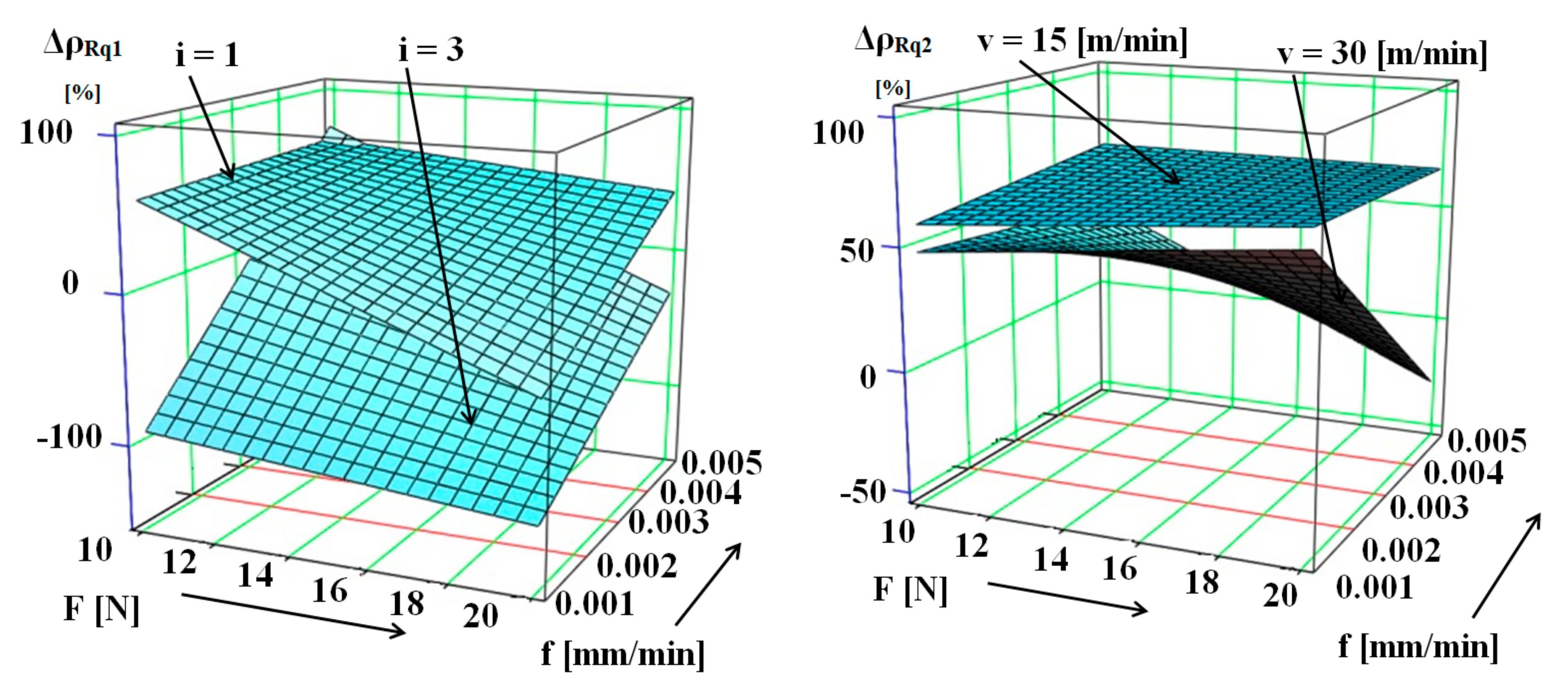
- On the base of main and cross-effect analysis, the following can be stated: In Experiment I, for both i1 = 1 and i2 = 3 number of passes, increasing the burnishing force from F1 = 10 N to F2 = 20 N had a negative effect on the numerical value of the surface-roughness-improvement ratio for all four characteristics (ΔσRa, ΔσRq, ΔσRz and ΔσRt).
- Increasing the feed from f1 = 0.001 mm/rev to f2 = 0.005 mm/rev for the number of passes i2 = 3 had a clear positive effect on the value of the surface-roughness-improvement ratio both when applying the burnishing force F1 = 10 N and F2 = 20 N. In contrast to this, in the case of the realization of the number of burnishing passes i1 = 1, a decrease in the value of the surface-roughness-improvement ratio can be discovered.
- In the case of Experiment II, increasing the burnishing force from F1 = 10 N to F2 = 20 N at v1 = 15 m/min burnishing speed showed a positive trend in the values of all the four (ΔσRa, ΔσRq, ΔσRz and ΔσRt) surface-roughness-improvement ratios for the low feed (f1 = 0.001 mm/rev).
- At the higher speed (v2 = 30 m/min), increasing the feed from f1 = 0.001 mm/rev to f2 = 0.005 mm/rev, when F2 = 20 N was used, had a negative effect on the tested surface-roughness-improvement ratios. Therefore, the application of a higher burnishing speed (v2 = 30 m/min) and a lower burnishing force (F1 = 10 N) is more beneficial in terms of surface-roughness improvement.
- In the future, we intend to examine the effect of the increased number of passes, and we intend to study the 3D roughness parameters to better understand the processes taking place during machining.
Author Contributions
Funding
Institutional Review Board Statement
Informed Consent Statement
Data Availability Statement
Acknowledgments
Conflicts of Interest
References
- Kovács, G. Combination of Lean value-oriented conception and facility layout design for even more significant efficiency improvement and cost reduction. Int. J. Product. Res. 2020, 58, 2916–2936. [Google Scholar] [CrossRef]
- Molnár, V. Minimization Method for 3D Surface Roughness Evaluation Area. Machines 2021, 9, 192. [Google Scholar] [CrossRef]
- Sztankovics, I.; Kundrák, J. The Characteristics Parameters of the Twist Structure on Cylindrical Surfaces Machined by Turning Procedures. Appl. Mech. Mater. 2014, 693, 418–423. [Google Scholar] [CrossRef]
- Nagy, A.; Varga, G. Effect of the Abandonment of Cooling and Lubrication on Surface Roughness and Cylindricity in Turning of Steel. Multidiscip. Sci. 2021, 11, 395–407. [Google Scholar] [CrossRef]
- Jerez-Mesa, R.; Plana-Garcia, V.; Lluma, J.; Travieso-Rodriguez, J.A. Enhancing Surface Topology of Udimet®720 Superalloy through Ultrasonic Vibration-Assisted Ball Burnishing. Metals 2020, 10, 915. [Google Scholar] [CrossRef]
- Lluma, J.; Gomez-Gras, G.; Jerez-Mesa, R.; Rue-Mascarell, J.; Travieso-Rodriguez, J.A. Mechanical Strengthening in S235JR Steel Sheets through Vibration-Assisted Ball Burnishing. Metals 2020, 10, 1010. [Google Scholar] [CrossRef]
- Basak, H.; Ozkan, M.T.; Toktas, I. Experimental Research and ANN Modelling on the Impact of the Ball Burnishing Process on the Mechanical Properties of 5083 Al-Mg Material. Kov. Mater. 2019, 57, 61–74. [Google Scholar] [CrossRef]
- Abo El-Nasr, A.A. Thermomechanical Fatigue Behavior of Burnished 7075-T6 Aluminium Alloy. In Proceedings of the 15th International Conference on Applied Mechanics and Mechanical Engineering (AMME), Cairo, Egypt, 29–31 May 2012; pp. 40–50. [Google Scholar] [CrossRef]
- Revankar, G.D.; Shetty, R.; Rao, S.S.; Gaitonde, V.N. Wear resistance enhancement of titanium alloy (Ti-6Al-4V) by ball burnishing process. J. Mater. Resear. Technol. 2017, 6, 13–32. [Google Scholar] [CrossRef] [Green Version]
- Kato, H.; Ueki, H.; Yamamoto, K.; Uasunaga, K. Wear resistance improvement by nanostructured surface layer produced by burnishing. Mater. Sci. Forum 2018, 917, 231–235. [Google Scholar] [CrossRef]
- Krishna, R.M.; Koorapati, E.P. A study of wear resistance of non-ferrous roller burnished components. Int. J. Appl. Manag. Sci. 2012, 3, 11–24. [Google Scholar]
- Rao, D.S.; Hebbar, H.S.; Komaraiah, M.; Kempaiah, U.N. Investigation on the effect of ball burnishing parameters on surface roughness and corrosion resistance of HSLA dual-phase steels. East Afric. J. Sci. 2008, 2, 164–169. [Google Scholar] [CrossRef]
- Dzionk, S.; Scibiorski, B.; Pryzybylski, W. Surface Texture Analysis of Hardened Shafts after Ceramic Ball Burnishing. Materials 2019, 12, 204. [Google Scholar] [CrossRef] [PubMed] [Green Version]
- Sharma, J.; Kapoor, J. To Investigate the Effect of Burnishing Parameters on the Surface Finish and Surface Hardness of Aluminium 7075 Cylinder Liners. IJAMR 2017, 9, 43–47. [Google Scholar]
- Ghodake, A.; Bhamre, V.G.; Londhe, B.C. Analytical and Experimental Investigation of Contribution of Burnihsed Parameters on Roughness and Micro Hardness of AA6351. Int. J. Appl. Innov. Eng. Manag. 2015, 4, 42–48. [Google Scholar] [CrossRef]
- Randjelovic, S.; Tadic, B.; Todorovic, P.M.; Vukelic, D.; Miloradovic, D.; Radenkovic, M.; Tsiafic, C. Modelling of the Ball Burnishing Process with a High Stiffness Tool. Int. J. Adv. Manuf. Technol. 2015, 81, 1509–1518. [Google Scholar] [CrossRef]
- Ferencsik, V.; Gál, V. Investigation of the effect of burnishing force on average surface roughness. Multidiscip. Sci. 2021, 11, 139–143. (In Hungarian) [Google Scholar] [CrossRef]
- Banh, Q.-N.; Nguyen, H.-D.; Tran, A.S. Numerical Simulation and Exprimental Validation of Surface Roughness by the Smoothing Small Ball-Burnishing Process. Machines 2021, 9, 48. [Google Scholar] [CrossRef]
- Dzierwa, A.; Markopoulos, A.P. Influence of Ball-Burnishing Process on Surface Topography Parameters and Tribological Properties of Hardened Steel. Machines 2019, 7, 11. [Google Scholar] [CrossRef] [Green Version]
- Kovács, Z.F.; Viharos, Z.J.; Kodácsy, J. The effect of magnetic assisted ball burnishing on the corrosion resistance of C45 steel. In Advances in Manufacturing Engineering and Materials II, Proceedings of the International Conference on Manufacturing Engineering and Materials (ICMEM 2021), Nový Smokovec, Slovakia, 21–25 June 2021; Lecture Notes in Mechanical, Engineering; Hloch, S., Klichová, D., Pude, F., Krolczyk, G.M., Chattopadhyaya, S., Eds.; Springer: Cham, Switzerland, 2021. [Google Scholar] [CrossRef]
- Řehoř, J.; Fulemová, J.; Monková, K.; Monka, P. Morphology of the Chip Formation at Orthogonal High Speed Milling of AISI H13. Key Eng. Mater. 2016, 686, 45–50. [Google Scholar] [CrossRef]
- Abodena, A. Optimization of Surface Roughness of Brass by Burnishing. Int. J. Eng. Inf. Technol. 2019, 5, 90–96. [Google Scholar]
- Luo, H.; Liu, J.; Wang, L.; Zhong, Q. The effect of burnishing parameters on burnishing force and surface microhardness. Int. J. Adv. Manuf. Technol. 2005, 28, 707–713. [Google Scholar] [CrossRef]
- Luo, H.; Liu, J.; Wang, L.; Zhong, Q. Investigation of the Burnishing Process with PCD Tool on Non-Ferrous Metals. Int. J. Adv. Manuf. Technol. 2005, 25, 454–459. [Google Scholar] [CrossRef]
- Rodriguez, A.; Calleja, A.; Lopez de Lacalle, L.N.; Pereira, O.; Gonzalez, H.; Urbikain, G.; Laye, J. Burnishing of SFW Aluminium Al-Cu-Li Components. Metals 2019, 9, 260. [Google Scholar] [CrossRef] [Green Version]
- Available online: https://www.alumeco.com/aluminium/bars/square-bars/en-aw-2011/10-mm/p/472/8999 (accessed on 1 July 2021).
- Vereschaka, A.A.; Vereschaka, A.S.; Grigoriev, S.N.; Kirillov, A.K.; Khaustova, O.U. Development and research of environmentally friendly dry technological machining system with compensation of physical function of cutting fluids. Procedia CIRP 2013, 7, 311–316. [Google Scholar] [CrossRef] [Green Version]
- Vereshchaka, A.S.; Vereshchaka, A.A.; Kirillov, A. Ecologically friendly dry machining by cutting tool from layered composition ceramic with nano-scale multilayered coatings. Key Eng. Mater. 2011, 496, 67–74. [Google Scholar] [CrossRef]
- Nguyen, T.-T.; Mia, M. Modelling and Evaluation of Energy Efficiency of New Hybrid Turning-Burnishing Process in Terms of Surface Properties. Energies 2020, 13, 4929. [Google Scholar] [CrossRef]
- Skoczylas, A.; Zaleski, K. Selected Properties of the Surface Layer of C45 Steel Parts Subjected to Laser Cutting and Ball Burnishing. Materials 2020, 13, 3429. [Google Scholar] [CrossRef] [PubMed]
- Saldana-Robles, A.; Plascencia-Mora, H.; Aguilera-Gomez, E.; Saldana-Robles, A.; Marquez-Herrera, A.; Diosdado-De la Pena, J.A. Influence of Ball Burnishing on Roughness, Hardness and Corrosion-Resistance of AISI 1045 Steel. Surf. Coat. Technol. 2018, 339, 191–198. [Google Scholar] [CrossRef]
- Balland, P.; Tabourot, L.; Degre, F.; Moreau, V. An Investigation of the Mechanics of Roller Burnishing Through Finite Element Simulation and Experiments. Int. J. Mach. Tools Manuf. 2013, 65, 29–36. [Google Scholar] [CrossRef]
- Dyl, T.C. The Burnishing Process of the Stainless Steel in Aspect of the Reduction Roughness and Surface Hardening. J. KONES Powertrain Transp. 2017, 24, 63–69. [Google Scholar] [CrossRef]
- Wang, X.; Zhu, L.; Zhou, Z.; Liu, G.; Liu, E.; Zeng, Z.; Wu, X. Tribological properrties of WC-reinforced Ni-based coatings under different lubricating conditions. J. Therm. Spray Technol. 2015, 24, 1323–1332. [Google Scholar] [CrossRef]
- Travieso-Rodriguez, A.J.; Gomez-Gras, G.; Dessein, G.; Carillo, F.; Alexis, J.; Jorba-Peiro, J.; Aubazac, N. Effects of ball-bursnihing process assisted by vibrations in G10380 steel specimens. Int. J. Adv. Manuf. Technol. 2015, 81, 1757–1765. [Google Scholar] [CrossRef] [Green Version]
- Tobola, D.; Rusek, P.; Czechowski, K.; Miller, T.; Duda, K. New Indicators of Burnished Surface Evaluation—Reasons of Application. Metrol. Meas. Syst. 2015, 22, 263–274. [Google Scholar] [CrossRef]
- Amdouni, H.; Bouzaiene, H.; Montagne, A.; van Gorp, A.; Coorevits, T.; Nasri, M.; Iost, A. Experimental Study of a Six New Ball-Burnishing Strategies Effects on the Al-Alloy Flat Surfaces Integrity Enhancement. Int. J. Adv. Manuf. Technol. 2017, 90, 2271–2282. [Google Scholar] [CrossRef] [Green Version]
- Johanyak, Z.C. Introduction to the Experimental Methodology; Lecture Notes; John Von Neumann University: Kecskemét, Hungary, 2002; pp. 8–21. (In Hungarian) [Google Scholar]
- Sipkas, V.; Vadasz Bognar, G. Failure Analysis of Structural Elements. Multidiscip. Sci. 2020, 10, 3–12. [Google Scholar] [CrossRef]
- E-Taweel, T.A.; El-Axir, M.H. Analysis and Optimization of the Ball Burnishing Process Through the Taguchi Technique. Int. J. Adv. Manuf. Technol. 2009, 41, 301–310. [Google Scholar] [CrossRef]
- Bagyinszki, G.; Bitay, E. Surface Treatment; Technical Scientific Booklets; Transylvanian Museum Association: Gundelsheim, Germany, 2009; pp. 59–85. (In Hungarian) [Google Scholar]
- He, B.; Ding, S.; Shi, Z. A Comparison between Profile and Areal Surface Roughness Parameters. Metrol. Meas. Syst. 2021, 28, 413–438. [Google Scholar] [CrossRef]
- Sanchez Egea, A.J.; Rodriguez, A.; Celentano, D.; Calleja, A.; Lopez de Lacalle, L.N. Joining Metrics Enhancement when Combining FSW and Ball-Burnishing in a 2050 Aluminium Alloy. Surf. Coat. Technol. 2019, 367, 327–335. [Google Scholar] [CrossRef] [Green Version]
- Huuki, J.; Hornborg, M.; Juntunen, J. Influence of Ultrasonic Burnishing Technique on Surface Quality and Change in the Dimensions of Metal Shafts. J. Eng. 2014, 2014, 124247. [Google Scholar] [CrossRef] [Green Version]
- Leach, R. Chapter 6—Surface Topography Measurement Instrumentation. In Fundamental Principles of Engineering Nanometrology, 2nd ed.; Micro and Nano Technologies; William Andrew: Norwich, NY, USA, 2014; pp. 133–204. [Google Scholar] [CrossRef]
- ISO 22081:2021; Geometrical Product Specifications (GPS)—Geometrical Tolerancing—General Geometrical Specifications and General Size Specifications. ISO: Geneva, Switzerland, 2021. Available online: https://www.iso.org/standard/72514.html (accessed on 1 June 2022).


| Si | Fe | Cu | Mn | Mg | Cr | Zn | Bi | Pb | Al | |
|---|---|---|---|---|---|---|---|---|---|---|
| Min | 3.3 | 0.5 | 0.4 | 0.3 | 0.2 | 89.3 | ||||
| Max | 0.4 | 0.8 | 4.6 | 1 | 1.8 | 0.1 | 0.2 | 0.6 | 0.6 | 95.1 |
| No. | Burnishing Parameters I | Burnishing Parameters II | Transformed Parameters | ||||||
|---|---|---|---|---|---|---|---|---|---|
| F (N) | f (mm/rev) | i (ø) | F (N) | f (mm/rev) | v (m/min) | x1 | x2 | x3 | |
| 1 | 10 | 0.001 | 1 | 10 | 0.001 | 15 | −1 | −1 | −1 |
| 2 | 20 | 0.001 | 1 | 20 | 0.001 | 15 | +1 | −1 | −1 |
| 3 | 10 | 0.005 | 1 | 10 | 0.005 | 15 | −1 | +1 | −1 |
| 4 | 20 | 0.005 | 1 | 20 | 0.005 | 15 | +1 | +1 | −1 |
| 5 | 10 | 0.001 | 3 | 10 | 0.001 | 30 | −1 | −1 | +1 |
| 6 | 20 | 0.001 | 3 | 20 | 0.001 | 30 | +1 | −1 | +1 |
| 7 | 10 | 0.005 | 3 | 10 | 0.005 | 30 | −1 | +1 | +1 |
| 8 | 20 | 0.005 | 3 | 20 | 0.005 | 30 | +1 | +1 | +1 |
| Mark | Name | Definition | Formula |
|---|---|---|---|
| Ra | Average roughness | Arithmetic means of the absolute height of the profile | |
| Rq | Root mean square roughness | Root mean square of the height of the profile | |
| Rz | Average roughness height | Average absolute value of the five highest peaks and the five lowest valleys | |
| Rt | Maximum height of the profile | Total height of the assessed profile |
| No. | Ra (µm) I. | ΔσRa (%) | Ra (µm) II. | ΔσRa (%) | ||
|---|---|---|---|---|---|---|
| Turned | Burnished | Turned | Burnished | |||
| 1 | 1.2260 | 0.3457 | 71.80 | 1.0117 | 0.4231 | 58.18 |
| 2 | 0.9213 | 1.2686 | −37.69 | 0.9299 | 0.2631 | 71.71 |
| 3 | 0.9947 | 0.3599 | 63.82 | 0.9374 | 0.3040 | 67.57 |
| 4 | 1.0679 | 0.5875 | 44.99 | 0.8834 | 0.3017 | 65.85 |
| 5 | 1.0118 | 1.8215 | −80.06 | 0.9524 | 0.4891 | 48.65 |
| 6 | 1.0622 | 2.2249 | −109.46 | 1.1319 | 0.4141 | 63.42 |
| 7 | 0.9450 | 0.2516 | 73.38 | 1.0559 | 0.6421 | 39.19 |
| 8 | 1.0741 | 1.3817 | −28.64 | 0.9814 | 1.2703 | −29.44 |
| No. | Rq (µm) I. | ΔσRq (%) | Rq (µm) II. | ΔσRq (%) | ||
|---|---|---|---|---|---|---|
| Turned | Burnished | Turned | Burnished | |||
| 1 | 1.4181 | 0.5772 | 59.29 | 1.2535 | 0.5190 | 58.59 |
| 2 | 1.1423 | 1.5577 | −36.37 | 1.1432 | 0.3272 | 71.38 |
| 3 | 1.2361 | 0.4491 | 63.67 | 1.1654 | 0.3826 | 67.17 |
| 4 | 1.3050 | 0.7527 | 42.32 | 1.1190 | 0.3697 | 66.96 |
| 5 | 1.2184 | 2.3315 | −91.36 | 1.1799 | 0.6170 | 47.71 |
| 6 | 1.2934 | 2.7763 | −114.65 | 1.3682 | 0.5019 | 63.32 |
| 7 | 1.1659 | 0.3142 | 73.05 | 1.2873 | 0.7910 | 38.55 |
| 8 | 1.3002 | 1.6946 | −30.33 | 1.1968 | 1.5383 | −28.53 |
| No. | Rz (µm) I. | ΔσRz (%) | Rz (µm) II. | ΔσRz (%) | ||
|---|---|---|---|---|---|---|
| Turned | Burnished | Turned | Burnished | |||
| 1 | 6.0651 | 2.7207 | 55.14 | 6.1135 | 2.7146 | 55.59 |
| 2 | 5.6889 | 6.7087 | −17.93 | 5.7399 | 1.8995 | 66.91 |
| 3 | 6.0100 | 2.5422 | 57.70 | 6.3137 | 2.3293 | 63.11 |
| 4 | 5.9449 | 4.0704 | 31.53 | 6.5407 | 2.0272 | 69.01 |
| 5 | 5.8470 | 8.9717 | −52.54 | 5.9786 | 2.9443 | 50.75 |
| 6 | 6.1230 | 10.3915 | −69.71 | 6.4803 | 2.4865 | 61.63 |
| 7 | 5.9639 | 1.9799 | 66.80 | 6.5035 | 4.0826 | 37.22 |
| 8 | 5.6166 | 6.8064 | −21.18 | 5.8492 | 7.0841 | −21.11 |
| No. | Rt (µm) I. | ΔσRt (%) | Rt (µm) II. | ΔσRt (%) | ||
|---|---|---|---|---|---|---|
| Turned | Burnished | Turned | Burnished | |||
| 1 | 7.4429 | 3.4059 | 54.24 | 7.6052 | 3.8576 | 49.28 |
| 2 | 6.6607 | 9.3875 | −40.94 | 7.8737 | 2.3713 | 69.88 |
| 3 | 7.1770 | 3.6195 | 49.57 | 8.5543 | 3.2045 | 62.54 |
| 4 | 6.7281 | 5.5299 | 17.81 | 9.5248 | 2.5208 | 73.53 |
| 5 | 6.9308 | 16.2023 | −133.77 | 7.1352 | 3.7538 | 47.39 |
| 6 | 6.7881 | 15.7811 | −132.48 | 7.9379 | 3.4761 | 56.21 |
| 7 | 7.1138 | 3.0610 | 56.97 | 8.5208 | 4.8280 | 43.34 |
| 8 | 6.2375 | 9.7202 | −55.83 | 7.5960 | 9.2197 | −21.38 |
| No. | ΔσRa (%) | R1 | ΔσRq (%) | R2 | ΔσRz (%) | R3 | ΔσRt (%) | R4 | Σ | R |
|---|---|---|---|---|---|---|---|---|---|---|
| 1 | 71.80 | 2 | 59.29 | 3 | 55.14 | 3 | 54.24 | 2 | 10 | 2 |
| 2 | −37.69 | 6 | −36.37 | 6 | −17.93 | 5 | −40.94 | 5 | 22 | 4 |
| 3 | 63.82 | 3 | 63.67 | 2 | 57.70 | 2 | 49.57 | 3 | 10 | 2 |
| 4 | 44.99 | 4 | 42.32 | 4 | 31.53 | 4 | 17.81 | 4 | 16 | 3 |
| 5 | −80.06 | 7 | −91.36 | 7 | −52.54 | 7 | −133.77 | 8 | 29 | 5 |
| 6 | −109.46 | 8 | −114.65 | 8 | −69.71 | 8 | −132.48 | 7 | 31 | 6 |
| 7 | 73.38 | 1 | 73.05 | 1 | 66.80 | 1 | 56.97 | 1 | 4 | 1 |
| 8 | −28.64 | 5 | −30.33 | 5 | −21.18 | 6 | −55.83 | 6 | 22 | 4 |
| No. | ΔσRa (%) | R1 | ΔσRq (%) | R2 | ΔσRz (%) | R3 | ΔσRt (%) | R4 | Σ | R |
|---|---|---|---|---|---|---|---|---|---|---|
| 1 | 58.18 | 5 | 58.59 | 5 | 55.59 | 5 | 49.28 | 5 | 20 | 5 |
| 2 | 71.71 | 1 | 71.38 | 1 | 66.91 | 2 | 69.88 | 2 | 6 | 1 |
| 3 | 67.57 | 2 | 67.17 | 2 | 63.11 | 3 | 62.54 | 3 | 10 | 3 |
| 4 | 65.85 | 3 | 66.96 | 3 | 69.01 | 1 | 73.53 | 1 | 8 | 2 |
| 5 | 48.65 | 6 | 47.71 | 6 | 50.75 | 6 | 47.39 | 6 | 24 | 6 |
| 6 | 63.42 | 4 | 63.32 | 4 | 61.63 | 4 | 56.21 | 4 | 16 | 4 |
| 7 | 39.19 | 7 | 38.55 | 7 | 37.22 | 7 | 43.34 | 7 | 28 | 7 |
| 8 | −29.44 | 8 | −28.53 | 8 | −21.11 | 8 | −21.38 | 8 | 32 | 8 |
| Experiment I | Experiment II |
|---|---|
| F1 = 10 N | F2 = 20 N |
| f2 = 0.005 mm/rev | f1 = 0.001 mm/rev |
| v2 = 30 m/min | v1 = 15 m/min |
| i2 = 3 | i1 = 1 |
Publisher’s Note: MDPI stays neutral with regard to jurisdictional claims in published maps and institutional affiliations. |
© 2022 by the authors. Licensee MDPI, Basel, Switzerland. This article is an open access article distributed under the terms and conditions of the Creative Commons Attribution (CC BY) license (https://creativecommons.org/licenses/by/4.0/).
Share and Cite
Ferencsik, V.; Varga, G. The Influence of Diamond Burnishing Process Parameters on Surface Roughness of Low-Alloyed Aluminium Workpieces. Machines 2022, 10, 564. https://doi.org/10.3390/machines10070564
Ferencsik V, Varga G. The Influence of Diamond Burnishing Process Parameters on Surface Roughness of Low-Alloyed Aluminium Workpieces. Machines. 2022; 10(7):564. https://doi.org/10.3390/machines10070564
Chicago/Turabian StyleFerencsik, Viktoria, and Gyula Varga. 2022. "The Influence of Diamond Burnishing Process Parameters on Surface Roughness of Low-Alloyed Aluminium Workpieces" Machines 10, no. 7: 564. https://doi.org/10.3390/machines10070564