1. Introduction
Transition away from fossil-fueled vehicles is a key strategy in the fight against the harmful CO2 emissions and climate change. Therefore, transportation electrification is rapidly accelerating across the globe. Electric vehicles (EVs) are recognized as the future for a zero-carbon transportation sector. As the market of EVs is growing larger, more advanced electrical machine designs will be necessary.
Recently, one of the major research themes in the design of electrical machines is increasing the power density (or) power per volume [
1]. The weight and size of the machine components play a vital role in the assembly of a higher power dense machine. In order to combine high performance with compact structure, material engineering for the active components (i.e., core or windings) as well as the passive components (i.e., insulation or heat exchangers) are necessary. Since the major part of the power losses is generated in the machine winding [
2], it is important to limit these losses by the adoption of innovative winding topologies and improved thermal management [
3].
The production technology of electrical machine windings always seeks for easily produced solutions with higher performance and lower cost. The manufacturing of machine windings basically depends on three main factors which are the electrical conductors, thermal and mechanical properties [
4]. The selection of the electrical conductor usually is based on the electrical properties of the material such as the electrical conductivity. Also, the individual conductors or strands are usually coated with an insulating layer in order to provide the required electrical and thermal properties such as voltage rating and temperature class [
5]. With this being said, appropriate material selection for the conducting material is important for high electromagnetic and thermal performances.
This paper provides a general overview about different multi-physic design aspects associated with the manufacturing of electrical machine windings. Such aspects include the electromagnetic performance, thermal management, and mechanical and noise troubleshooting. Many studies are compared and summarized more than any other previous work, offering a quick and comprehensive reference to the readers for a better selection of a suitable winding topology. The paper is divided to the following main sections. In
Section 2, different conducting materials are introduced and compared. In
Section 3, different magnet wire topologies are compared including round, rectangular, and litz wires.
Section 4 shows different examples additively manufacturing coils. In
Section 5, the common challenges facing the machine windings are presented, including AC high frequency losses, winding cooling, and insulation aging.
2. Conducting Materials
A magnet’s wire can be made from different materials depending on the required characteristics such as conductivity, mechanical performance, corrosion resistance, bending properties and temperature coefficient. In the following sub-sections, the standard winding materials are investigated along with other materials such as carbon nanotube, and the high-temperature superconducting windings.
2.1. Typical Materials of Magnet Wire
As a standard material, copper (Cu) has been widely used in many electromagnetic applications due to its high electrical conductivity (58 MS/m at 20 °C, 100% IACS–International Annealed Copper Standard). The combination of low resistivity and fair cost has led to a large yearly demand of the mined metal which is over 25 million tons with over 3% of annual increase rate [
6].
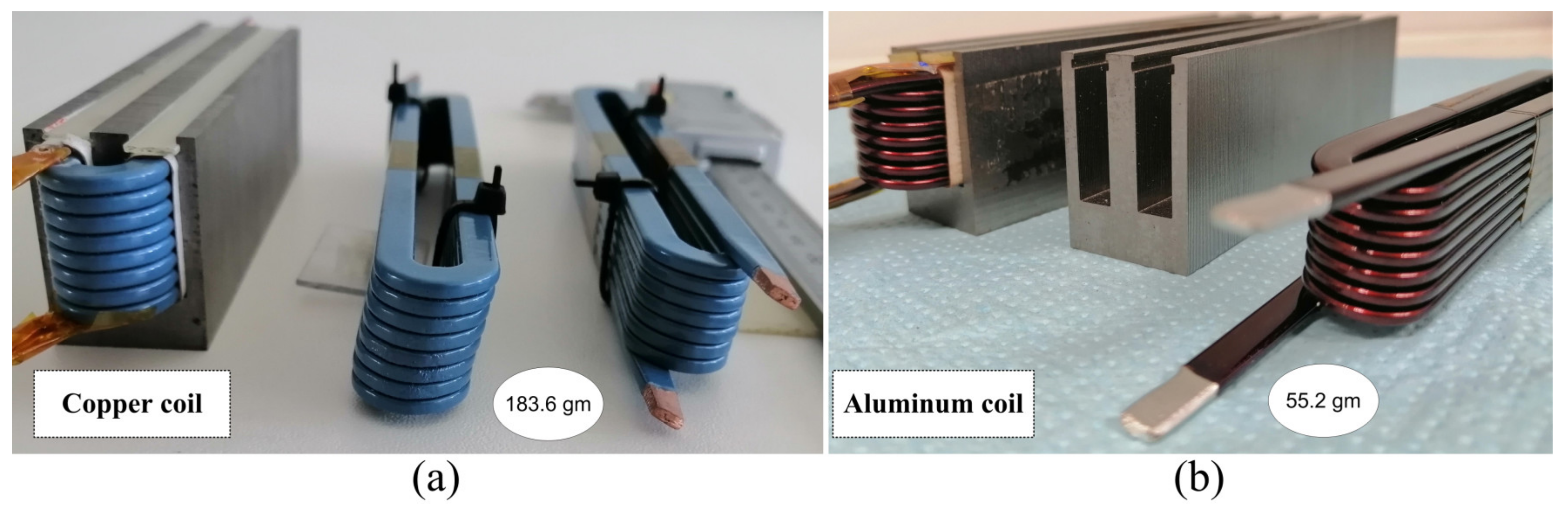
Alternatively, wires made from aluminum may be used owing to their lower mass density as well as lower cost compared to copper. Compared to copper, one of the main disadvantages of aluminum is that it has a lower electrical and thermal conductivities, with 65% and 53% respectively, which make it a suitable choice for low-cost electrical machines and squirrel cage bars of the induction machines. However, in some high-speed applications, the disadvantage of low conductivity can be overlooked due to high frequency effects. Another disadvantage is that although the cost of the raw material of aluminum is dramatically lower than copper, the cost of the ready-to-wind aluminum magnet wire is very close or even similar to this in copper magnet wires. That is mainly due to the low demand and the relatively poor commercial availability. In [
7], a comparison between both materials is conducted as shown in
Figure 1. It is concluded that aluminum can be a better replacement for copper at high frequency domain.
2.2. Copper Alloys
In other occasions, an interesting combination between copper and aluminum metals can be used as in the copper clad aluminum (CCA) wire [
8]. In these kind of wires, an aluminum rod is surrounded by a surface layer of copper with 5 to 15% of the overall cross section area [
9]. Such compromise between copper and aluminum has many advantages. CCA wire has lower weight and cost than pure copper. Also, it is more conductive and reliable than pure aluminum. This conductor can be beneficial at high frequencies operation with the presence skin effect due to the copper cladding. Therefore, it is widely used in radio frequency (RF) antennas, cable television, and voice coils. Similarly, some other applications use special types of copper alloys such as silver-plated copper wire [
10] or nickel-coated copper wires. The latter has been successfully used in extremely high-temperature electrical machines [
11].
2.3. Carbon Nanotube
Recently, in some special applications, copper is replaced by other conducting non-metal material such as carbon nanotube (CNTs) and graphene [
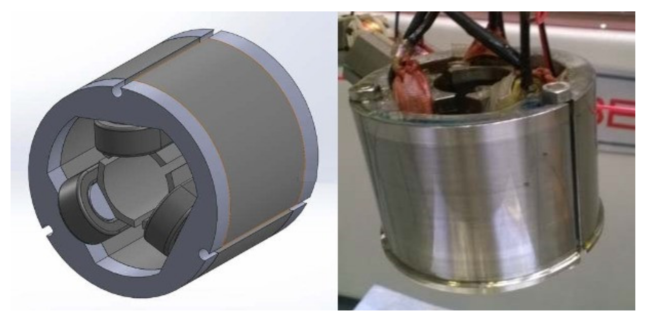
12]. These types of windings have the benefit of high conductivity with reduced mass density. Additionally, CNTs have low temperature coefficient, which means that their resistance will not increase remarkably when the temperature rises. Furthermore, there is no skin effect in CNTs, that is why they will have a better performance at high frequency application. In [
13], for higher energy efficiency, a three phase 40 W, 15,000 RPM motor was designed using CNT concentrated windings, shown in
Figure 2. In another application [
14], a 5 hp coreless axial flux PM machine was designed using CNTs for lower windings losses.
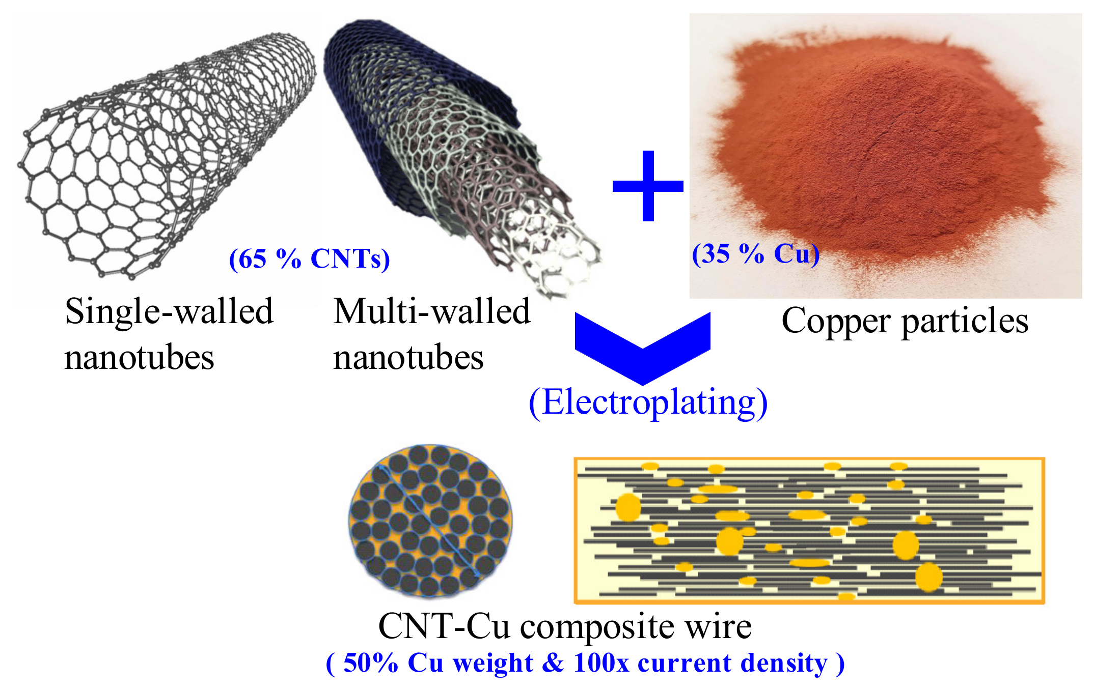
Moreover, CNTs can be mixed with copper as shown in
Figure 3. Compared to bulk copper windings, the mass density, when using 45% CNTs, is reduced by 40% [
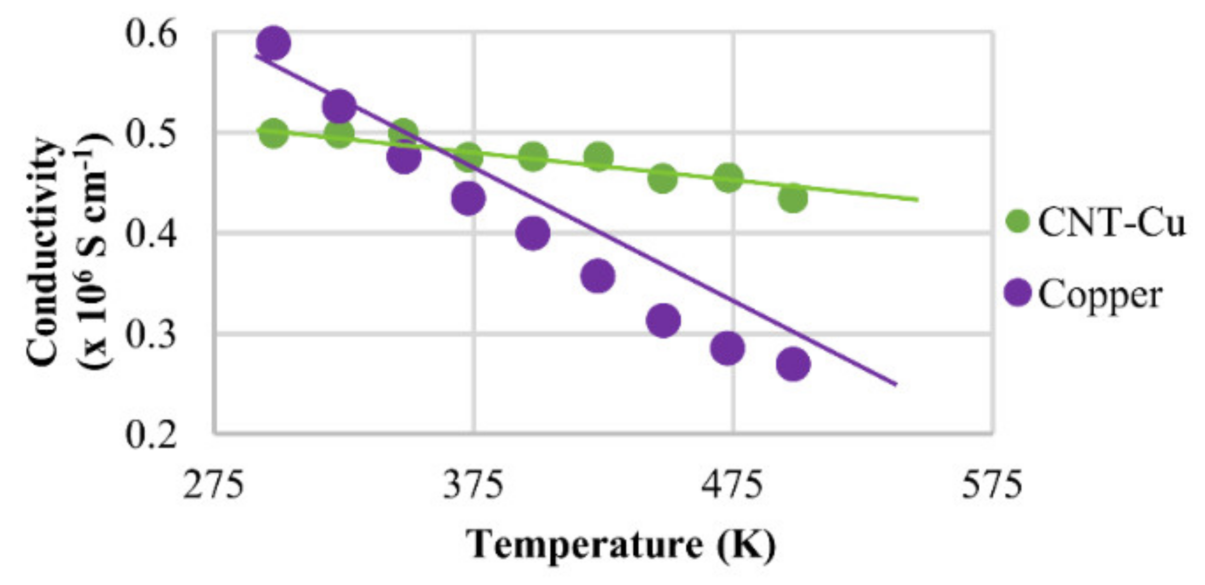
15]. Also, the electrical conductivity increased by over 25%. Thereby, these kinds of composites help in achieving high power density motors. In addition, unlike pure metals (Cu, Al, Ag, etc.) in which the electrical conductivity decreases significantly with temperature rise, the conductivity in CNTs–Cu composite deceases slightly with the same temperature rise as shown in
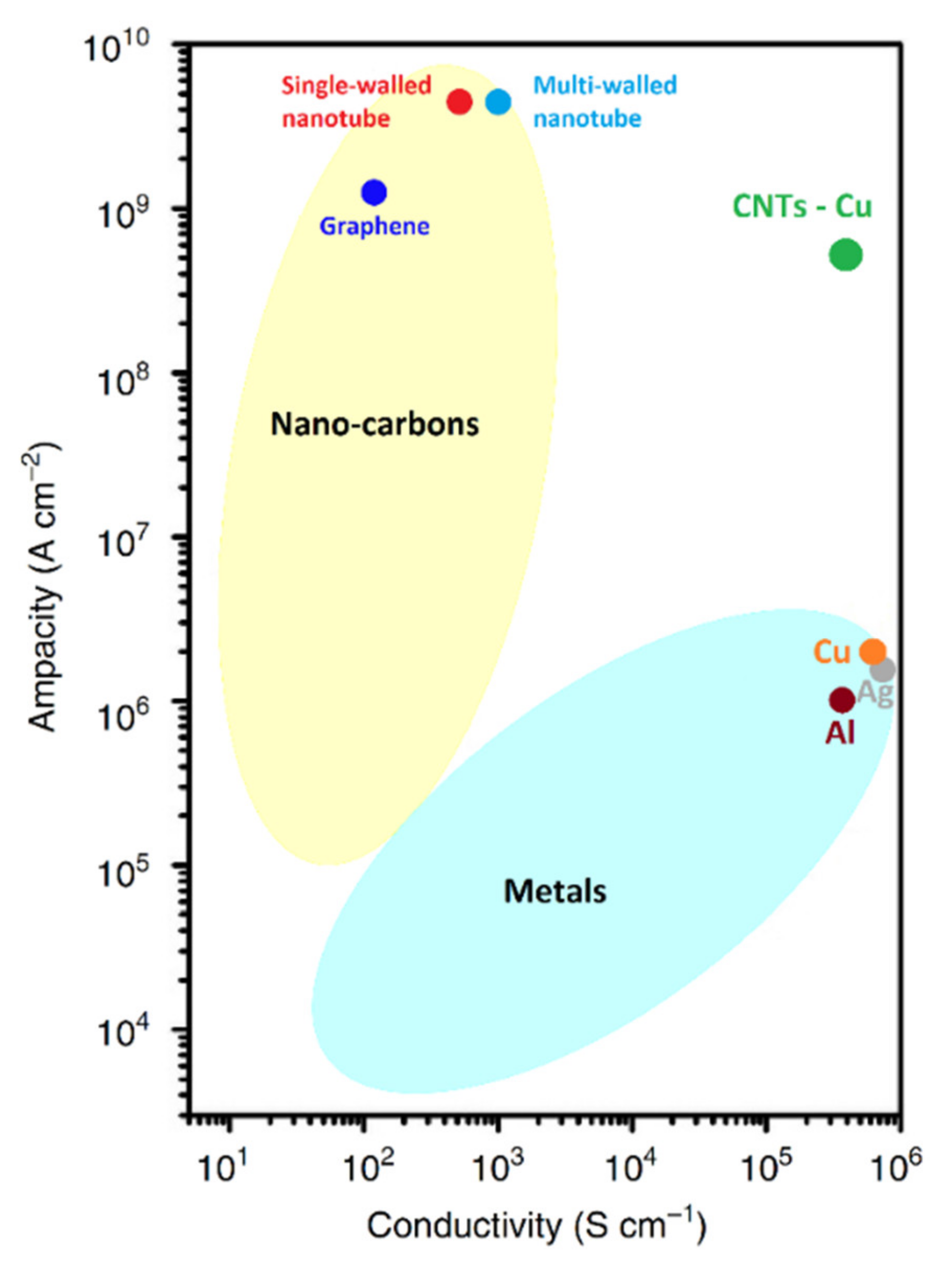
Figure 4. Another important advantage of CNTs–Cu composite is the high current carrying capacity (Ampacity). For instance, a combination of 65% of CNTs and 35% of copper particles will not only reduce the conductor weight to half, but also it will increase the ampacity by over 100 times [
15,
16].
Figure 5 shows a comparison between the ampacity in metals with CNTs. The same figure shows that CNTs- Cu composite will merge between the high conductivity of metals and the high ampacity of CNTs.
Lately, there are some ongoing research development on CNTs such as Cu-Al-CNT composite [
17] and nanometal interconnected carbon wires [
18]. Finally, the electrical, thermal, and physical properties of CNTs and other conducting metals (Cu, Al, Ag) are listed in
Table 1.
2.4. High-Temperature Superconducting (HTS) Windings
High temperature super conductors are considered one of the promising solutions for many electromagnetic devices and rotating machines such as those used in electric vehicles and ships [
19,
20]. The HTS conductor has the ability of carrying high current values with low amount of winding losses. Also, they are employed for achieving high efficiency and high-power density in many lightweight applications.
Many studies on HTS electrical machines have been reported in the literature [
21,
22,
23,
24,
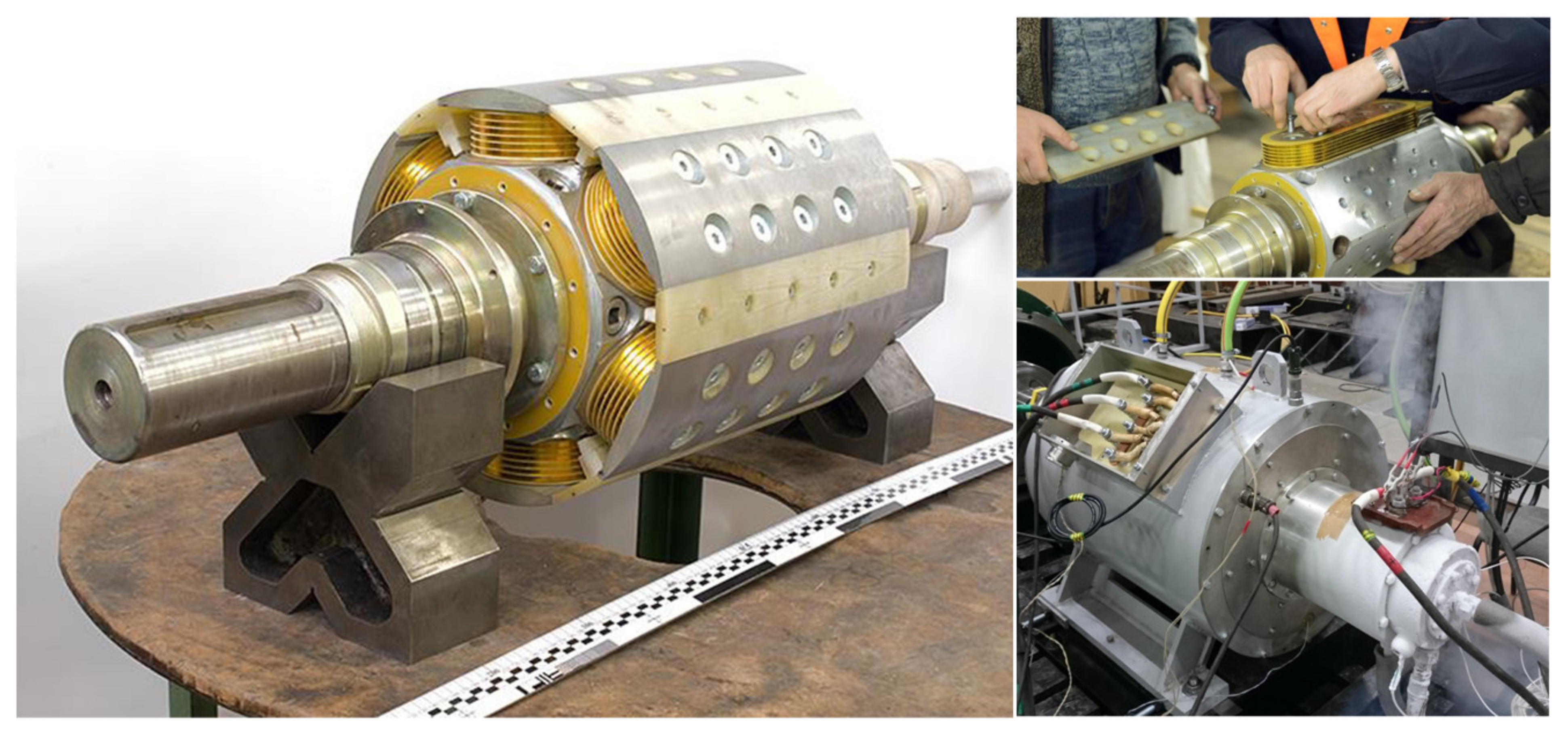
25]. An example to demonstrate, in [
26], a 200 kW three-phase 6-pole synchronous motor was designed and tested. The rotor is assembled using 2G HTS field coils as shown in
Figure 6. In these types of coils, the resistance transfer to zero state at the temperature near to 80 °K. Also, a cooling pipe with a rotating inlet is designed specially to transport the nitrogen liquid to the HTS coils.
One of the main applications of these superconductors are the HTS DC magnets. With a conductor current density of over 300 A/mm
2, the HTS DC magnet can produce very high magnetic field up to 23 T [
27].
The commercialization of HTS windings is still limited due to some technical issues such as the extreme mechanical stress which leads to a severe degradation in the performance of the conductors. Additionally, it is difficult to protect the magnets during unintended thermal runaway or at other worse heat scenarios.
3. Different Magnet Wire Topologies
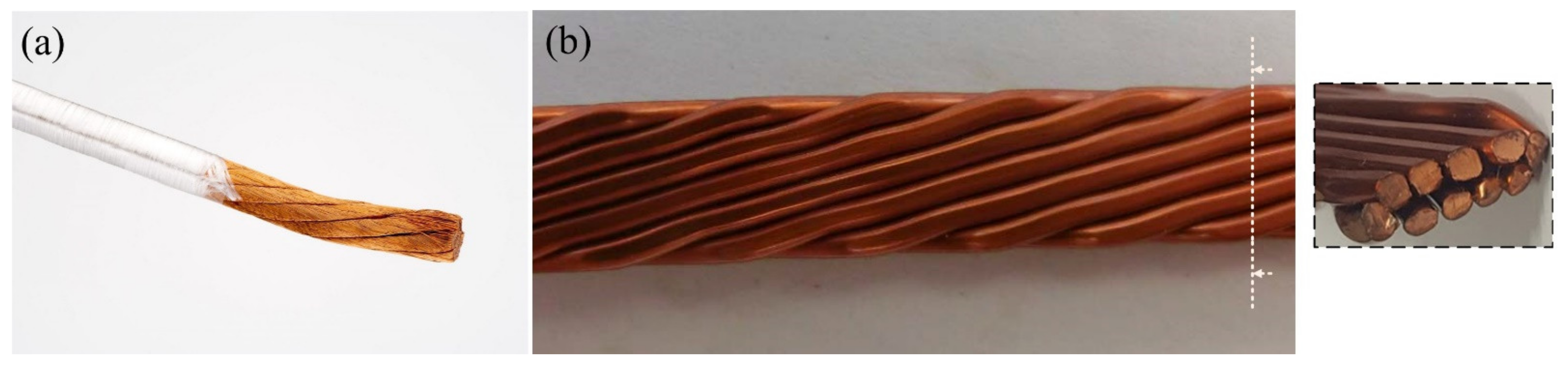
3.1. Single Round and Stranded Wires
Single round wires are the standard choice for most electrical machines and applications [
28]. Such conductors are typically placed randomly inside the stator slot [
29]. Additionally, these conductors can be divided into multiple parallel strands for a better mitigation of AC high frequency losses caused by skin and proximity effects [
30,
31]. These windings have also high mechanical fixability, and consequently easier manufacturability and lower cost. However, such windings have a very low fill factor with a range of 35–45% [
32]. Additionally, this topology has long end winding specially when using a distributed winding arrangement, resulting in a less efficient operation.
One of the common standards that defines the diameters of round and solid electrically conducting wires is the American wire gauge (AWG). The diameter of each gauge is an important factor for determining its current-carrying capacity. AWG can also be used in a stranded wire. In such case, the net area is the sum of the single strands areas without considering the intermediate airgaps. Thereby, for the same AWG, a solid wire will always have a slightly lower overall diameter. Unlike solid wires, stranded wires are identified by three numbers, the overall AWG size, strands number, and the strand AWG. For example, a 10 AWG 7/20 stranded wire is a 10 AWG wire made from seven strands of 20 AWG wire. Different conductor sizes of this wire gauge system are listed in [
33].
3.2. Rectangular and Hairpin Wires
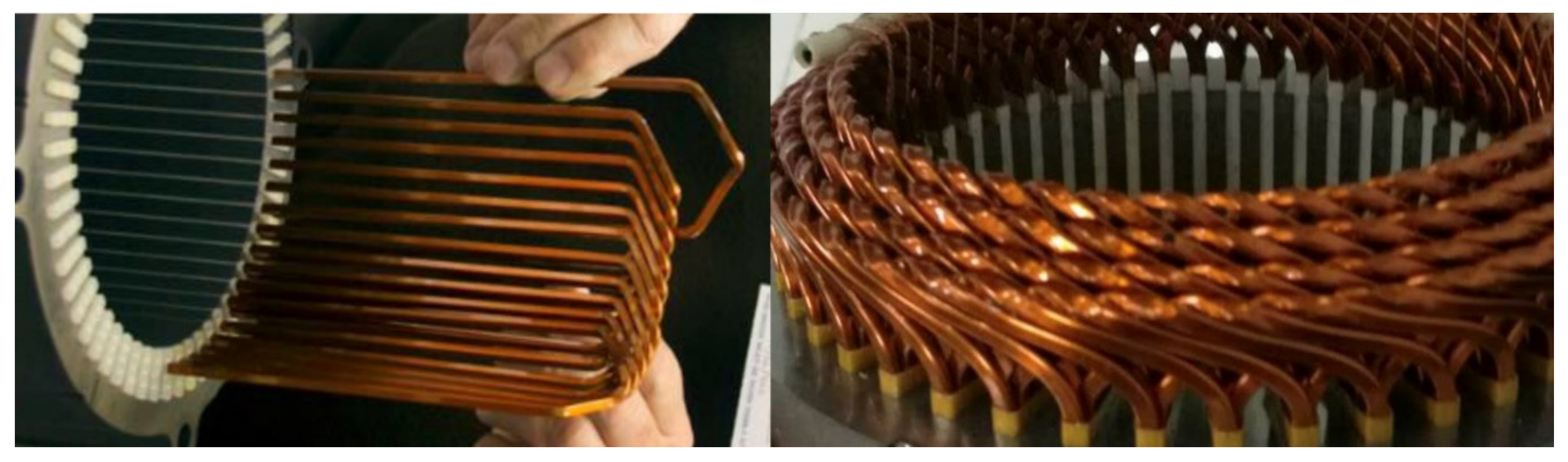
Rectangular conductors are a strong candidate for high performance electrical machines. Owning to its high filling factor and high thermal performance, this type of wire is considered as one of the most promising solutions for high-power density motors. Moreover, rectangular windings can be easily manufactured in an automatic mass production process, so it has a reduced cost. Currently, there are two common types of these windings which are hairpin winding and continuous multi-layer winding as shown in
Figure 7 [
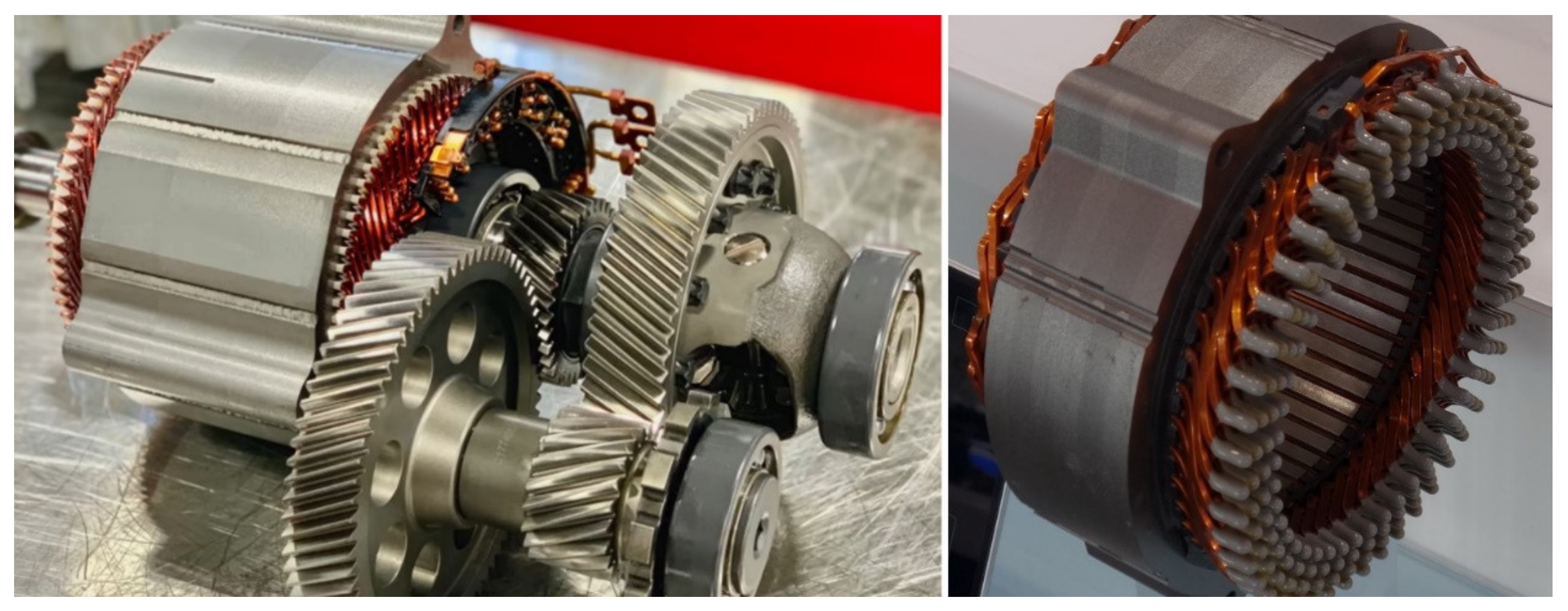
34]. The hairpin wire has additional design advantages, such as the possibility of using fully close stator slots. This since the rectangular bar is inserted into the stator slot by pushing it from the stator side, not through the slot opening. Therefore, many manufacturers in the electric vehicle markets have already been using rectangular hairpin windings in many car models such as Chevrolet Bolt and Volt Hybrid. Also, the new generation of Prius cars in Toyota have been using the same high performance conductors. Two examples of electric vehicle motors applying rectangular hairpin are shown in
Figure 8 [
35,
36].
Although the rectangular conductor looks promising, there are some challenges and limitations. For instance, with higher thickness compared to round or stranded wires, rectangular wires can be subjected to high eddy current losses especially at high frequencies. Moreover, in order to ensure that the hairpin winding is electrically continuous, there would be high number of bending and welding points required [
37,
38].
3.3. Litz Wire
Besides electrical machines, litz wire has been a vital component in the design of many electromagnetic devices such as inductors [
39], transformers [
40]. Litz wire is engineered so that it allows the current to be divided uniformly between strands. With twisted insulated strands, litz wire has been considered as a practical solution to mitigate the AC losses in the conductors of the electrical machines, especially at high frequency operation. Additionally, it has a relatively good mechanical flexibility compared to solid or rectangular conductors [
41].
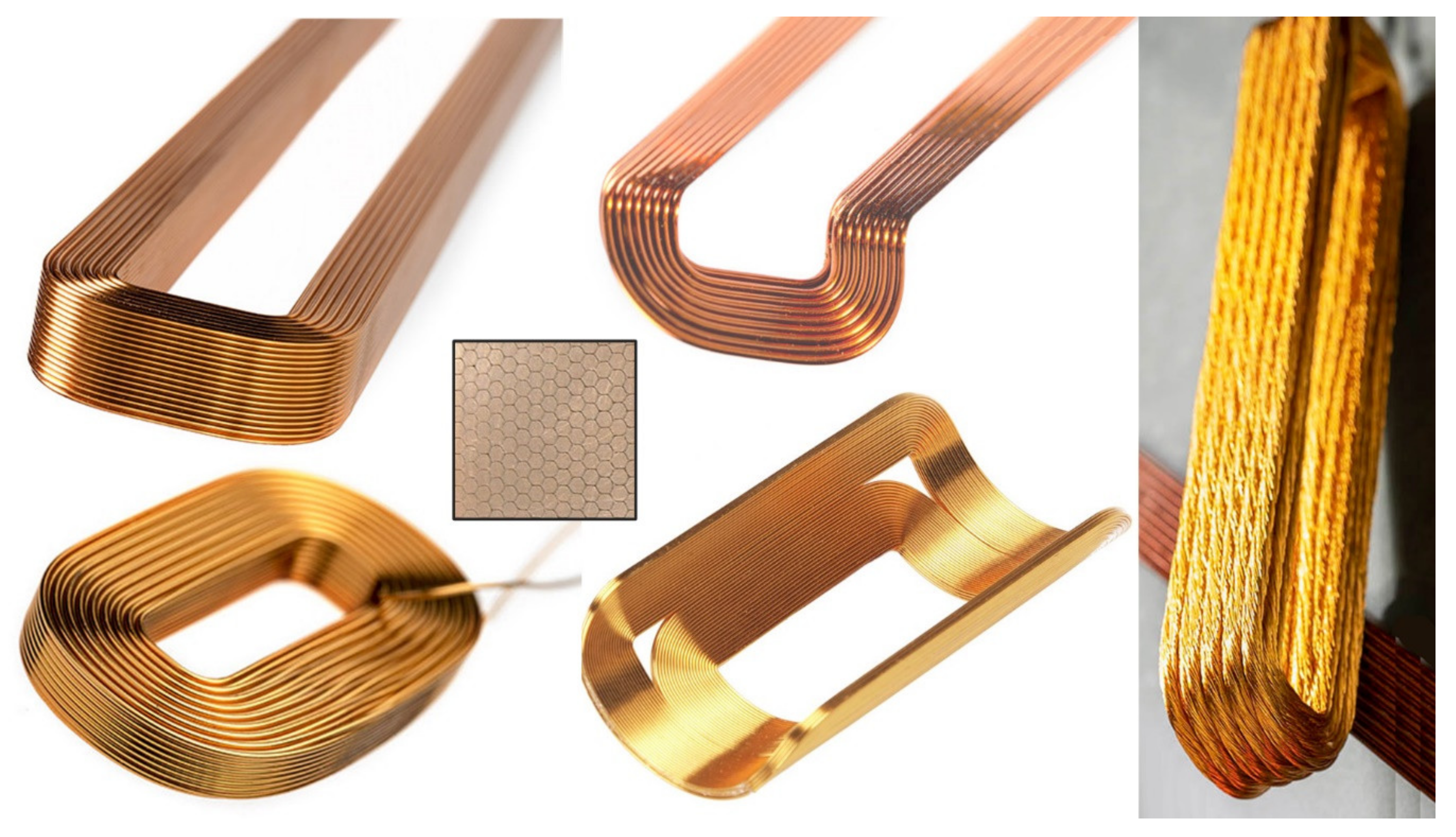
In terms of wire profile, as demonstrated in
Figure 9, there are eight common constructions for litz wires starting from single twisted round strand (Type 1) [
42]. Type 2 uses multiple bundles of type 1. Type 3 has three sub-levels of strands with bundles of type 2. Types 4-6 are similar to type 3 with an additional core and optional bundle textile. All of the previous six profiles have a round outer shape. Only types 7 and 8 have a rectangle shape with sub-conductors transposed equally along the axial length. Type 8 has a unique compact rectangular profile for high fill factor and better space utilization.
For the sake of low conduction losses and easy solderability, the insulation material used for litz wire is mostly Polyurethane (NEMA standard: MW 79—National Electrical Manufacturers Association). Sometimes, an additional nylon overcoat is used to increase the abrasion resistance and improve the winding space factor by applying an extra compaction on the strands. In this case the technical naming of the insulation type is Polyurethane Nylon-155 (MW 80) or Polyurethane Nylon-180 (MW 83) [
43].
From small ballasts in fluorescent lighting to large generators in wind turbines, litz wire has been widely used in different applications as listed in details in as listed in details in
Table 2 [
44]. It is reported that types 2 and 8 are the most common wires for most kind of application. Both types are practically showcased in
Figure 10 [
45,
46,
47].
3.4. Orthocyclic Coils
An orthocyclically wound coil has the advantage of a high copper fill factor (often between 60–70%), resulting in a higher magnetic field with a regular distribution in the smallest possible slot area. These self-supporting coils can be designed in many different custom shapes, as shown in
Figure 11, without a coil-former carrier. A transverse section of an orthocyclic coil have a honeycomb shape. So, these windings are manufactured with the densest possible stacking compared to their counterparts of random wound coils. Typically, Orthocyclic coils are wound with thermotank thermal bonding wire, where it is glued into a compact shape after heating [
48]. These coils are also characterized by high quality factor, which means lower losses and better suitability under high frequency operation. Additionally, they have good heat conduction and high vibration resistivity.
4. Winding Insulation Systems
More than 30% of electrical machines can experience failure due to insulation problems [
49,
50]. Over the past two decades, the dielectric strength of insulation materials has been gradually enhanced. There have been plenty of efforts to reduce the insulation thickness for more efficient and compact design with lower manufacturing cost [
51]. Despite the fact that the electrical insulation materials are passive components, they are considered as a very critical component in the design of electrical machines. The winding insulation is always used to prevent interconnection between the turns or between the winding and the core. Additionally, a farther protection can be provided to the body of the fully formed windings by impregnating or using suitable lining materials. That will help in the improvement of the physical properties including the mechanical ones such as mechanical stress resilience between conductors.
The insulating material is also the main criterium for the machine cooling and determining the maximum operating temperature of windings in the electrical machine. Accordingly, it defines the upper limit of the current that a wire can carry and hence the electrical loading and torque production. For instance, two identical wires with only different insulating material can withstand different levels of current density, despite having the same conducting material and cross section area. Any damage to the insulating material caused by overloading or hotspots can eventually cause machine failure. So, it necessary to select the insulation properly to provide the machine with the ultimate protection under worst heat scenarios including faults.
According to IEC standard 60085, the electrical insulations are classified based on their maximum temperature as shown in
Figure 12. The upper temperature limit in each insulation type is determined by three main terms; the ambient temperature (usually 40 °C), the permissible temperature rise, and safety margin. If the machine operating temperature exceeds the maximum temperature of the insulation material, the lifetime of the insulation will substantially decrease. An example to demonstrate according to NEMA standard, a machine operating at 180 °C can run safely on a class H insulation for tens of thousands of hours. However, using class F will reduce the lifetime to 8500 h. Classes B or A will reduce the lifetime to 1800, 300 h, respectively.
It is very important to detect the weakness in the winding insulation in an early stage so that a scheduled maintenance or replacement can be performed before any expected severe failure. In this context, many in-depth studies has been reported in literature for testing and monitoring techniques. In [
52,
53,
54,
55], many surveys have been carried out on electrical insulation diagnostics associated with the ongoing research developments.
4.1. Insulation Materials
The winding insulation materials are classified and selected mainly based on their thermal class and withstand capacity. They can also be classified based on the type of the substances. The motor winding insulation can be either liquid-based such as (e.g., synthetic varnishes, risen, etc.) or solid material such as (e.g., glass, rubber, ceramics, etc.).
Appendix A Table A1 shows different film insulation materials with their thermal class and advantages/disadvantages of each case. Similarly,
Appendix A Table A2 provides the same classification for tapes and fibers [
56].
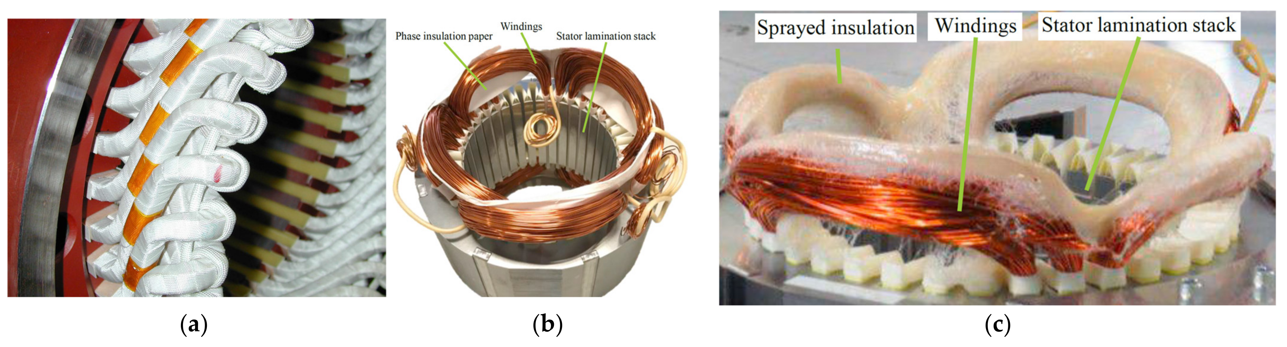
In high rating electrical machines (50–500 kW), a more sophisticated insulation system will be necessary specially with rated voltages up to 3000 V. An example to demonstrate is shown in
Figure 13a, which is a three-phase 350 kW asynchronous traction motor with a rated voltages of 1200 V [
57]. A class 200 insulation system is designed and tested which consists of three main components. First, the winding wire insulation (turn insulation) consists of polyimide film combined with braided glass silk. Secondly, the main insulation on the coil sides and end windings are made of mica/glass silk tapes with aramid-fiber-reinforced mica. Finally, the overall installation is vacuum-pressure impregnated with silicone resin material to eliminate moisture and provide deeper penetration of insulation.
In lower rating electrical machines [
58], traditional low-cost insulation paper is usually used between the phases and between the windings and the stator core as shown in
Figure 13b. For a faster and more reliable insulation process, spray insulation can be used as shown in
Figure 13c.
4.2. Failures of the Insulation System
There are three main reasons for failure in insulation material, which are thermal, electrical and mechanical stresses. The thermal stress is the root cause thermal ageing. For instance, a thermal overloading, caused by a small voltage unbalance of 3.5%, will increase the temperature by 25% in the phase carrying the highest current [
59]. Subsequently, this will accelerate the aging process of the insulation material remarkably. In terms of electrical stress, the breakdown in dielectric materials can happen as a result of manufacturing defects, transient voltages and partial discharge including tracking & corona phenomena. However, these failures are most likely to occurs at an operating voltage above 600 V. As for the negative effect of transient voltage, it mostly appears at variable frequency drives, especially at the startup or stopping. Finally, the windings material can be exposed to mechanical stresses, particularly in the moving coils of the rotor. The mechanical force on the conductors is proportional to the square of the machine current, so it is expected that this force can be most damaging at the starting of a motor.
4.3. Testing Insulation
Before putting an electrical machine into action, or during a periodic maintenance and fault-finding process, insulation testing and measurements are necessary in order to verify its suitability. These kinds of tests are referred to as offline tests. Normally, the offline test is more accurate and direct without much experience needed compared to online monitoring. Several techniques of testing and maintenance have been discussed in details in many standards [
60].
A commonly used test is the insulation resistance (IR) which can be measured using a megger device. This test is performed by applying a DC voltage between the windings and the machine frame/ground for a period of 10 min or more. The leakage current (usually in micro Ampere) is measured along with the test voltage and the insulation resistance can be calculated using ohm’s law. A temperature correction is also applied to the measured resistance if the test temperature is different from IEEE standard temperature (40 °C).
Table 3 shows the standard DC test voltages for different rated voltages. The recommended values for the insulation resistance are also listed in
Table 3 [
59,
61].
Additionally, the polarization index (PI) can also be calculated using this equation (PI = R10min /R1min), which is the ratio between the winding insulation resistance measured after applying the test voltage for 10 min to its value after 1 min. The PI is an important indicator to the dryness of the machine windings, especially if they are kept in a place with high humidity. A PI between 2–4 is considered a good value. Apart from IR and PI tests, other offline methods to test electrical insulation system are summarized in
Table 4 [
59,
61,
62].
5. Additive Manufacturing for Machine Windings
With the limited flexibility of the conventional techniques of winding manufacturing, standard shapes and standard materials are the only available options for the electrical machines. In this context, the interest in additive manufacturing (AM) of windings has been remarkably increasing recently [
63]. Using AM has enabled new design solutions with unmatched geometrical flexibility, improved material utilization, and ease of manufacturability. The following examples are showing the latest advancements of AM in the design of machine windings, which are demonstrating different levels of maturity.
5.1. Shape-Profiled Coils
Only a few examples have been reported in literature of shape profiled windings. In [
64], a coil is fabricated with different profiled turns using selective laser melting (SLM) as shown in
Figure 14a. This coil is mainly designed for a low-loss filter inductor. A copper alloy powder is used to print the coil. However, the measured electrical conductivity was 51% IACS, which is very poor compared to commercial copper. In [
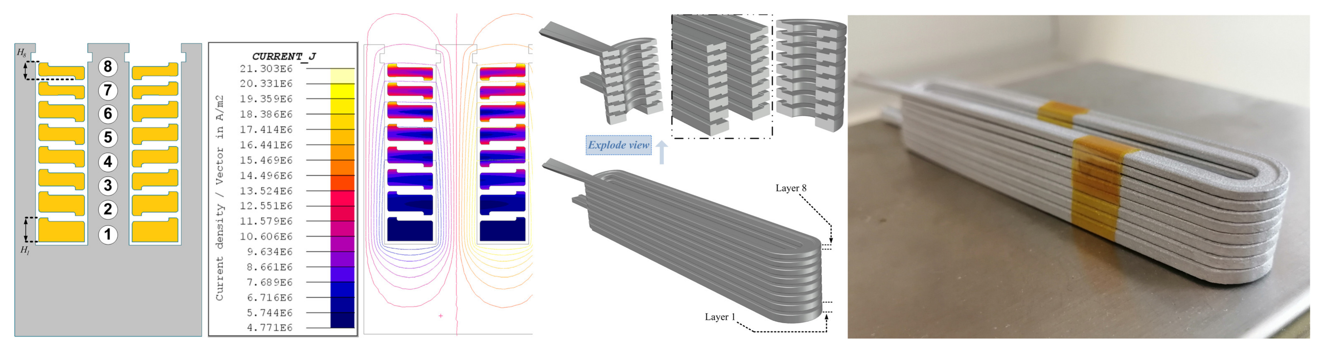
65], shape profiled coils are introduced to minimize the AC high frequency loss in the electrical machine by reducing the interaction between the slot leakage flux and the cross section area of conductors. Using CuCr1Zr alloy, the electrical conductivity has increased significantly to 75% IACS. Further, the coil end windings are optimized as shown in
Figure 14b for a better electromagnetic performance. Further, in [
66], AM shape profiled windings with uneven layers are proposed for weight sensitive and high frequency applications as shown in
Figure 15. With only 26% of the weight, this aluminum-based coil can limit high eddy current losses at high frequency.
5.2. Multi-Material Printing
All of the above examples are for coils printed using single material. Therefore, a post process is needed for adding coating for the coil turns. In order to avoid adding the electrical insulation in a post process, multi-material printing is introduced in [
67]. Here, using 3D extrusion-based printing, the authors prototyped a copper coil simultaneously with ceramic insulation for a 32-kW switched reluctance machine as shown in
Figure 16. Compared to conventional resin, the ceramic insulation of these coils managed to withstand a temperature of 300 °C, allowing for an increased current loading capability. Yet, thermal expansion of the multi-material parts is still quite challenging due to the introduced mechanical defects especially at high temperatures.
5.3. Integration with Cooling Channels
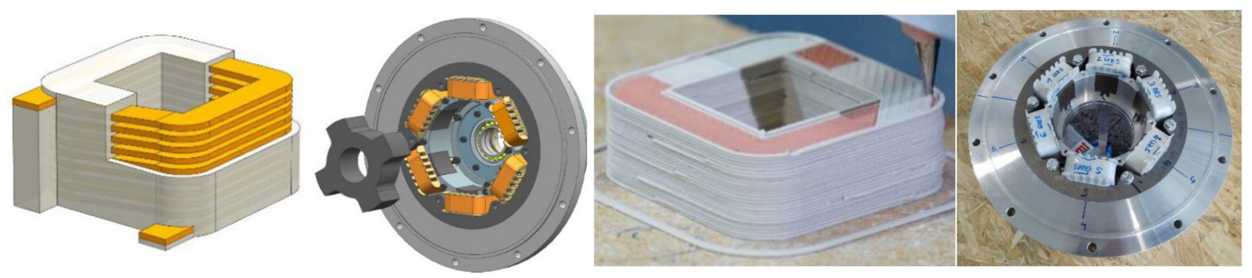
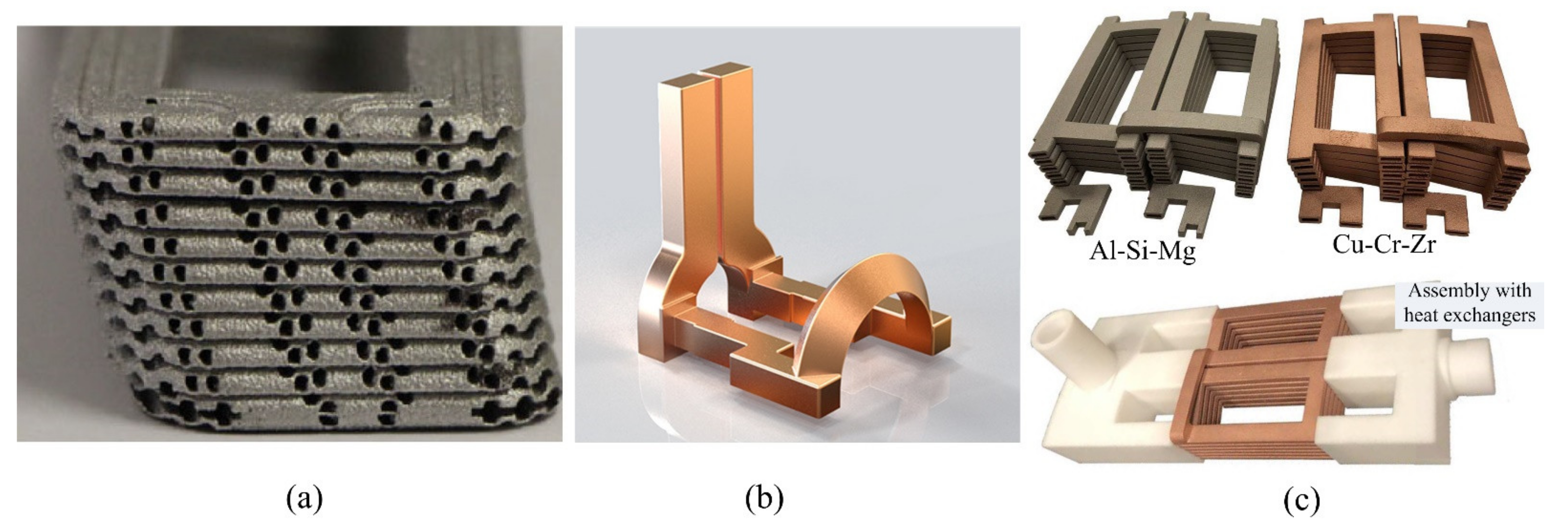
For a further thermal improvement, the printed coils can be integrated with cooling channels as shown in
Figure 17. In
Figure 17a, an aluminum alloy (Al-Si-Mg) is used as a feedstock for printing a concentrated coil with integrated cooling channels. With the proposed direct heat extraction, the coil reached a maximum current density of 100 A/mm
2 [
68]. Another example is shown in
Figure 17b. Here, a liquid cooled copper coil is prototyped for induction heating [
69]. Despite having no direct relation to AM machines, this example demonstrates the potential of 3D printing for commercial application. In
Figure 17c, using SLM, coils with hollow conductors are printed two different materials of copper and aluminum alloys [
70]. Targeting high power density electrical machines, the materials are compared in terms of chemical composition, electrical conductivity, and mechanical properties. It was found that Cu-Cr-Zr alloy will provide a high conductivity as well as good mechanical properties. However, building small details such as thin walls is still challenging. As for the Al-Si-Mg alloy, the electrical conductivity is about 50% of its value in the copper alloy. However, high electromagnetic performance is achieved at high frequency operation due to the higher resistivity provided by the aluminum-based coil against the high eddy currents.
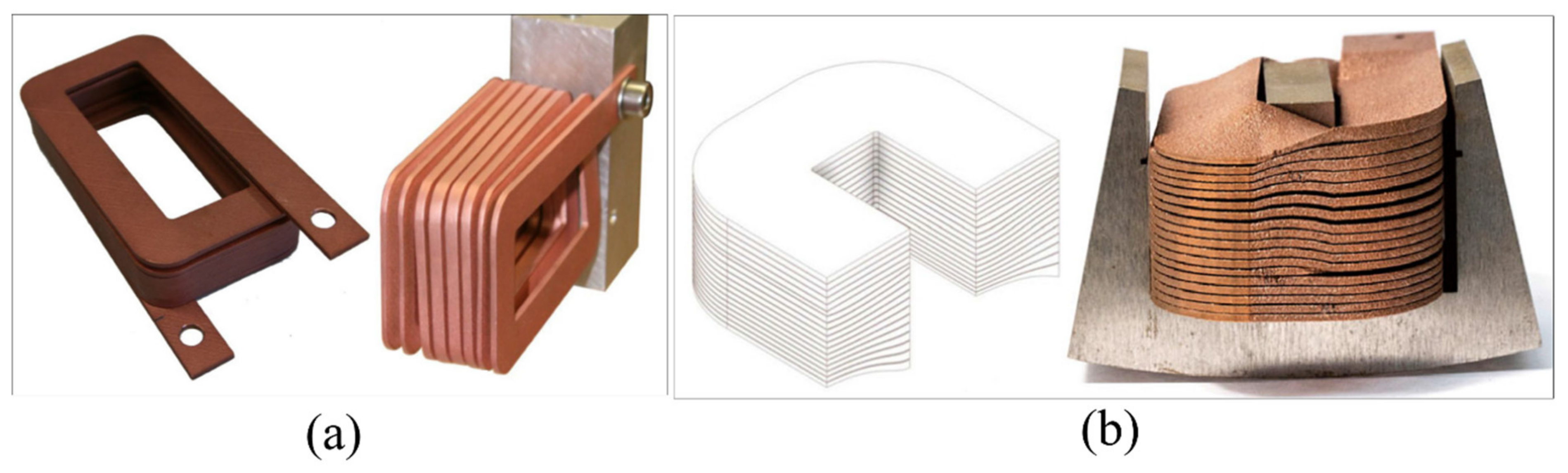
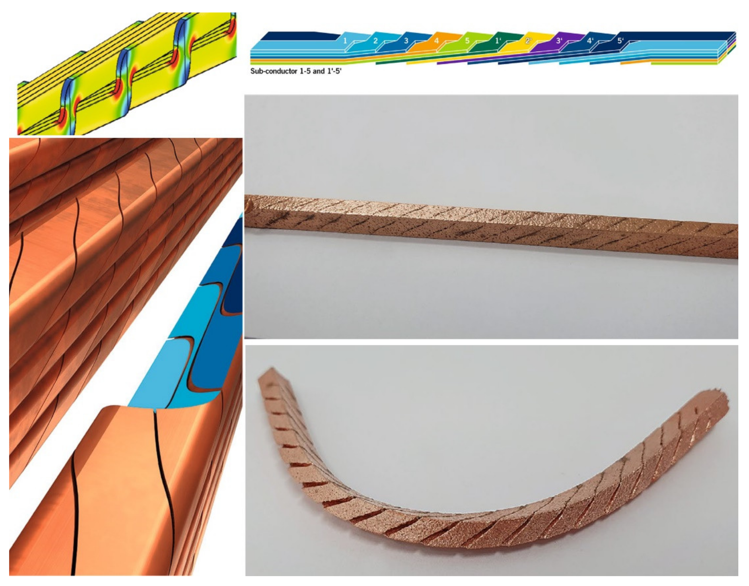
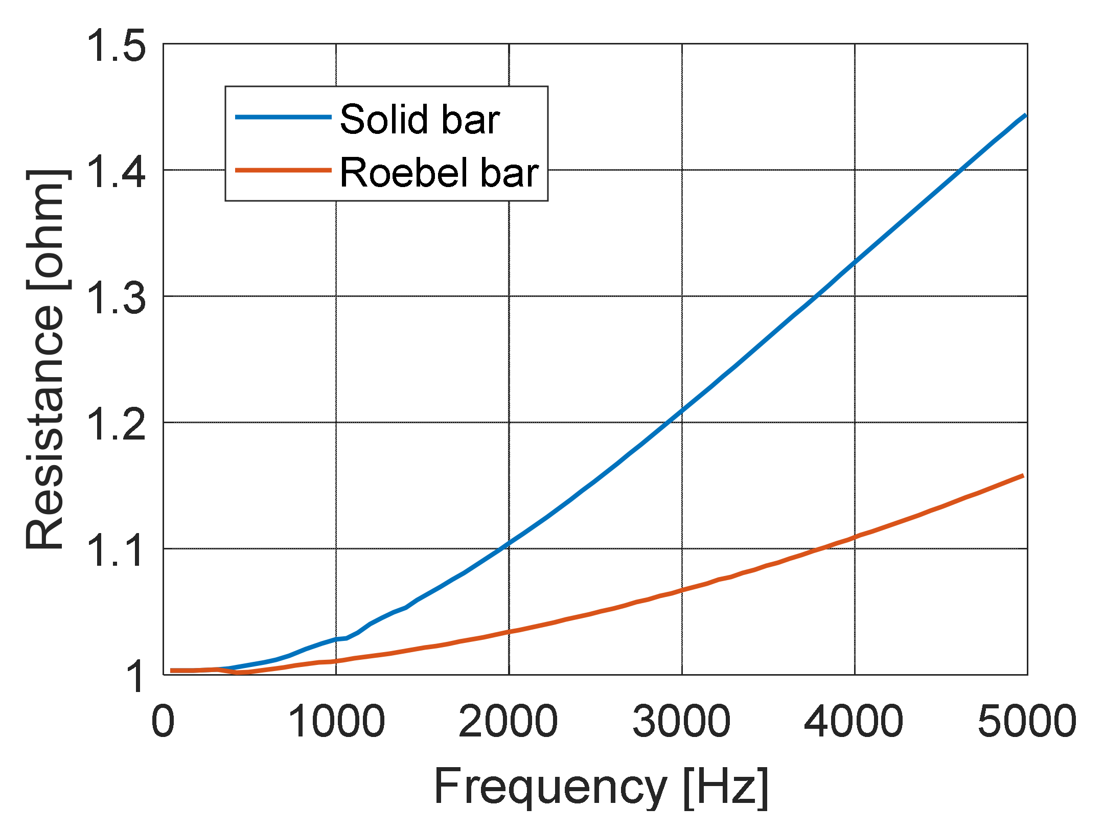
5.4. Multi-Strand Windings
For high-speed electrical machines, the AC loss can be crucial specially at high frequencies. Therefore, using multistrands coils is a good strategy for the mitigation of skin and proximity effects. Using conventional stranded coils can reduces the fill factor remarkably to 30–40% specially if the strands are twisted. In the contrast, AM has better design solutions which combine multi-strand approach with high fill factor. An example is shown in
Figure 18 for AM Roebel bar windings with twisted rectangular cross section strands [
71]. Using SLM, copper powder is used with 99.95 % purity to guarantee the best possible electrical conductivity. Compared to the conventional Roebel bars, the time and cost required for machinery and bending steps of are no longer necessary. Using vacuum pressure die-casting, the individual strands are coated by pressing an impregnating material between the copper structures. As a result, the air is displaced to ensure an effective electrical insulation. Finally, the resistance at different frequencies is compared with conventional solid bars as shown in
Figure 19. It is clear that the twisted Roebel bar has remarkably low AC losses specially at high frequencies.
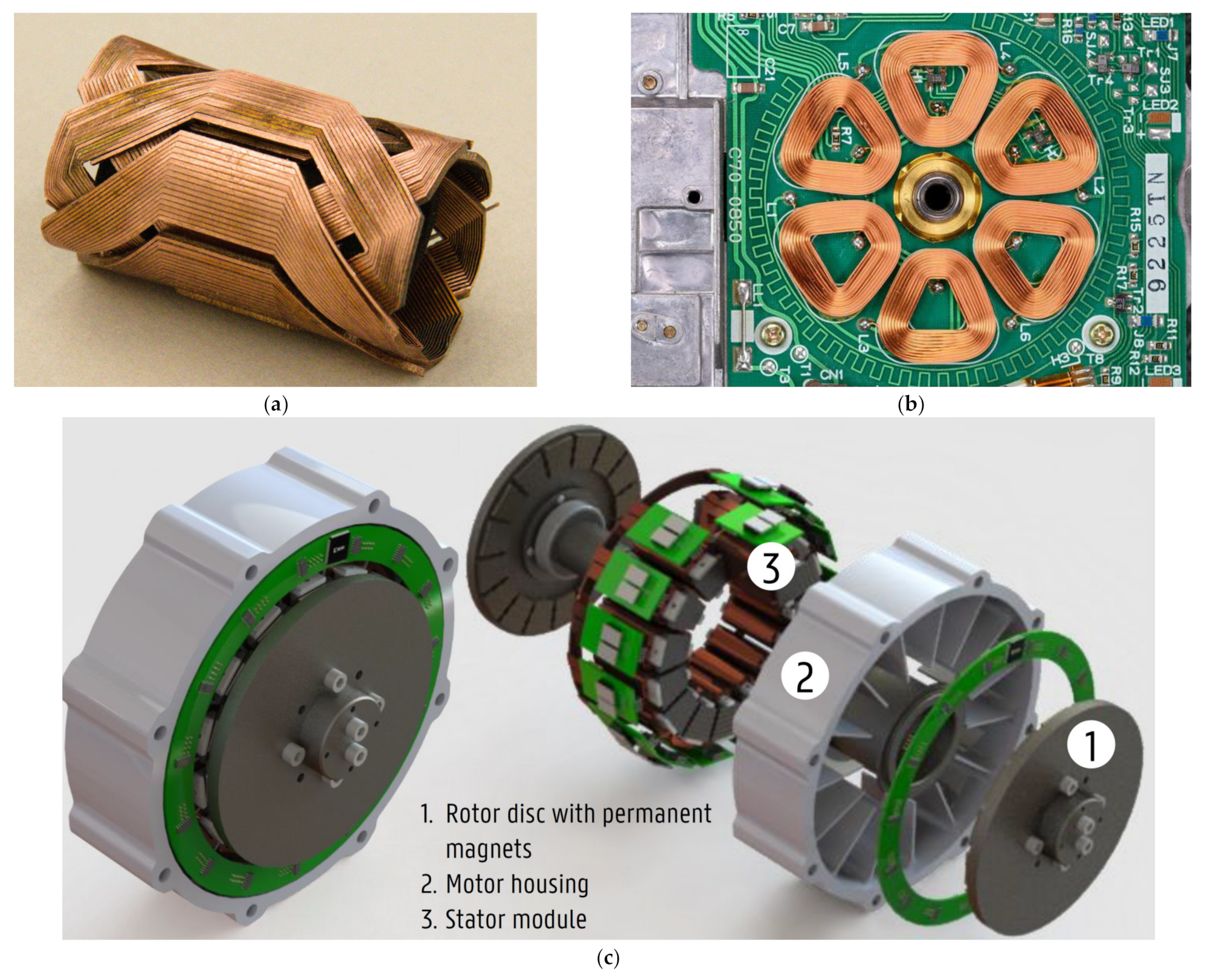
5.5. Slotless, PCB Windings and Modular Electrical Machines:
Typically, slotless windings are used in small-size and very-high-speed electrical machines [
72,
73]. Unlike traditional windings, slotless windings can be easily arranged in the machine airgap. Also, with no slotting harmonics, the rotor experiences less eddy current losses as well as zero cogging torque. In [
74], a six-coil winding was manufactured for PM brushless DC machine (BLDC) using a 1-mm sheet of copper as shown in
Figure 20a. Although the initial prototype is manufactured using laser cutting, the authors declared that the optimized shape of these windings will only be possible to produce using AM due to the high degree of freedom. Besides, the fill factor of the AM windings will be much higher, and the machine torque can be improved by 24%. Another form of windings for the BLDC machine is using printed circuit board (PCB) as shown in
Figure 20b [
75]. Furthermore, integration of power electronics on the machines outer frame can be made as shown in the example shown in
Figure 20c, which is referred to as modular electric machines [
76]. In such machines, the stator core and the power electronic modules share the same cooling jacket to improve the machine power density.
6. Challenges and Design Solutions
To avoid the machine failure, the windings must have high qualifications in terms of electrical, mechanical, and thermal aspects. The following subsections investigate different challenges facing the design of machine winding from a multi-physic point of view.
6.1. AC Losses and Fill Factor
Commonly, the higher the slot fill factor, the better the winding thermal performance would be. However, in terms of electromagnetic performance, this is not applicable all of the time specially in many modern high-speed machines. The main reason is that, at high frequencies operation, the AC eddy current effects should be considered such as skin and proximity effects. That is why the winding design is more complicated, since there are different key factors should be accounted for, such as conductor shape, arrangement and allocation in the machine slots. Therefore, a tradeoff between the slot fill factor and the conductor AC losses is necessary to reach an optimum performance.
Many strategies have been reported in literature in order to tackle the AC high frequency conduction losses. The subdivision of the single conductor into smaller strands is the most common one. This method depends mainly on using less cross-sectional area for each sub conductor in order to provide a better distribution of the high frequency current between the conductor strands. However, it has been experimentally concluded that this technique is not good enough to mitigate the AC losses [
77,
78]. The main reason is the parasitic circulating currents between the strands which can reach high values despite the low cross section area of each one. Another technique, which can provide further loss minimization, is applying strands transposition such as in the cases of litz wire and Roebel bars. This way, the circulating currents can be effectively reduced, but with sacrificing the fill factor.
In [
79], form-wound armature windings are developed for high-frequency 1-MW, 15,000 RPM PM synchronous machines (PMSM) as shown in
Figure 21. By utilizing type-8 litz wire, the form-wound, concentrated windings have greatly reduced the AC loss. With a rectangular formed shape, a high copper fill factor is achieved, resulting in a minimized DC loss component. Also, for space requirement reasons, the wires are bent at the end-winding region.
6.2. Mechanical and Acoustic Considerations
Under high operating constraints, electrical machines can present mechanical and acoustic problems such as noise and vibration. That is why magneto-mechanical analysis is important to study the interactions between electromagnetism and mechanics [
80]. In [
81], multi-physic FEM for vibration and acoustic analysis of PM synchronous machine is reported including the electromagnetic forces acting on the stator windings. Additionally, the authors proposed mitigation techniques in order to damp these noises using active or passive noise control. In [
82], the electromagnetic forces experienced by the end windings are calculated for a 900 kW, 4 poles induction machine during the transient current of a line starting circuit. The reliability of the winding insulation and support structure are both evaluated by the results from the electromagnetic force. In another study [
83], a numerical approach for vibration analysis is introduced to study the winding influence on the mechanical response of electrical machines. This research highlighted the importance of accounting for the winding presence in the vibration analysis, which results in a reduction in the associated deformations and a shift in the frequencies of the deformation modes.
6.3. Thermal Management
Thermal management is an important aspect in design of an efficient electric machine [
84]. Usually, the largest part of machine losses comes from the conductor losses. The thermal performance of the windings is one of the key limiting factors that define current carrying capacity, overloading capability, and operating range [
85]. PM machines, in particular, requires a careful thermal analysis in order to avoid magnet demagnetization [
86,
87]. In [
88], the authors investigated the effect of stator winding topology and the winding encapsulation material on the machine thermal performance. It was found that both factors have a strong influence on the thermal performance.
Conventional heat extraction methods, using shaft-mounted fans or housing fins, have a limited effect on the improvement of the machine thermal performance. For high-power density machines, advanced cooling methods are recently becoming more popular [
89]. A common method is forced liquid cooling using water jackets or cooling channels, which can provide a more efficient heat dissipation.
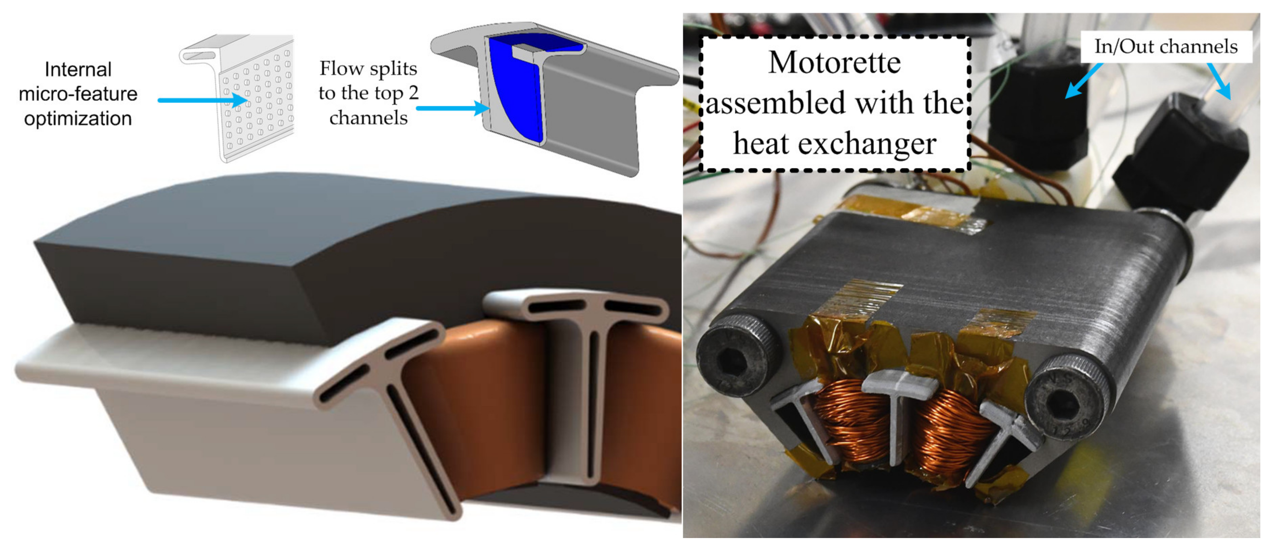
In [
90,
91], the machine windings are directly cooled using 3D printed ceramic heat exchangers as shown in
Figure 22. By occupying the unused space between the double layer concentrated windings, the power density of electric machines is increased without impacting the electromagnetic design. The microfeatures of inner channels are optimized using different shapes for a significantly improved cooling. Ceramics are selected due to their ability to withstand extremely high temperatures. As a result, the winding temperature rise is decreased by 44%. Also, a continuous current density of 35.7 A/mm
2 is achieved while keeping the maximum winding temperature below 200 °C.
The above-mentioned direct cooling methods can provide excellent cooling capabilities within the active region of windings. Nonetheless, the heat dissipation at the end-winging part is not improved much.
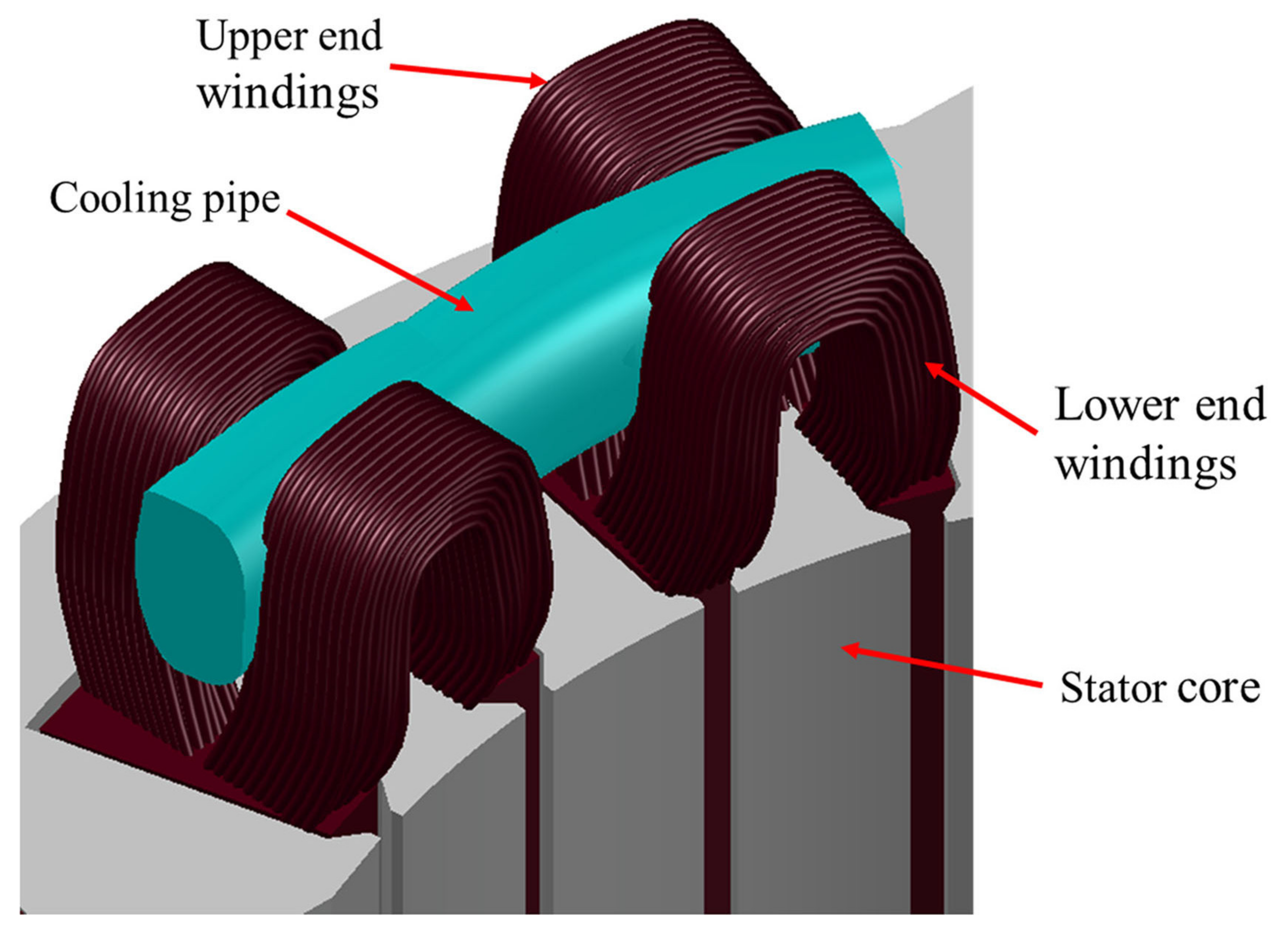
6.4. End-Winding Cooling
End-windings are commonly identified as the main hot-spot of the electrical machines [
89]. For a higher reliability of the cooling system, an improved cooling method is presented for stator end-windings of random wound electrical machines in [
92,
93]. As shown in
Figure 23, using a dedicated liquid-carrying pipe, the proposed cooling method is very cost-effective and can be applied to different existing machines used in automotive traction.
In [
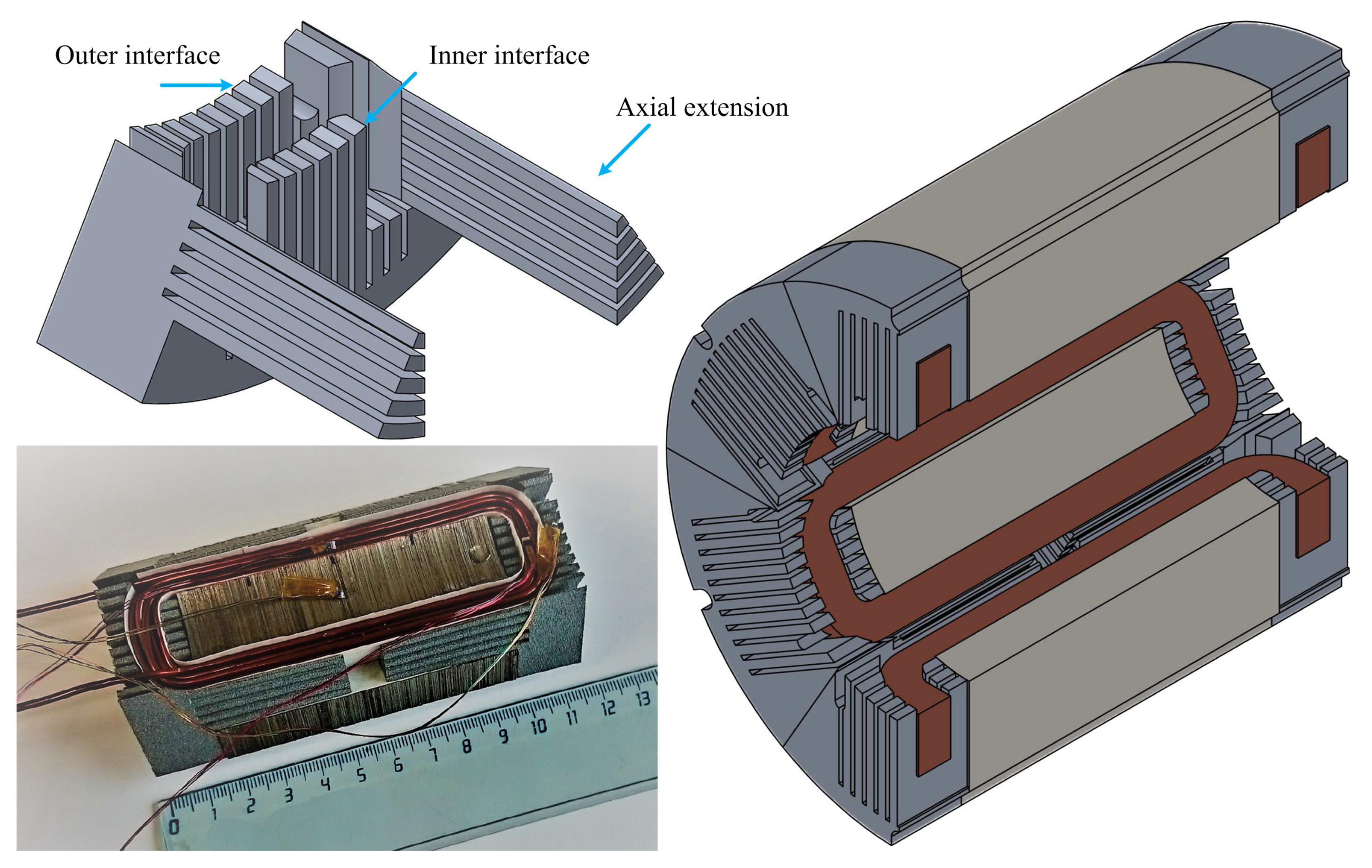
94], a thermally conductive insert piece is proposed which encloses the stator end-windings, and provides more contact between the end-windings and the machine housing as shown in
Figure 24. The thermal contact is further improved by making axial extensions that fill the triangular unused space between two adjacent coils. With these additional extensions inside the stator slots, the proposed indirect cooling concept is very effective compared to traditional cooling techniques such as forced air and water jacket. The current density is improved from 19.0 A/mm
2 to 26.5 A/mm
2 in 6/4 switched reluctance machine using this extended end-winding cooling inserts. Nevertheless, the introduced cooling system is only compatible with concentrated windings.
6.5. Insulation Aging and Partial Discharge
The lifespan of the electrical machine insulation system can be affected by different factors. For instance, thermal, electrical, mechanical and environmental stresses can cause an early failure of the insulation material [
95]. By the way of example, a 10 °C increase in temperature halves the lifetime of the insulation system [
59,
96]. With this being said, having a reliable insulation system can save cost and time by avoiding unplanned maintenance.
Partial discharge (PD), in particular, has been identified as the most likely cause of failure [
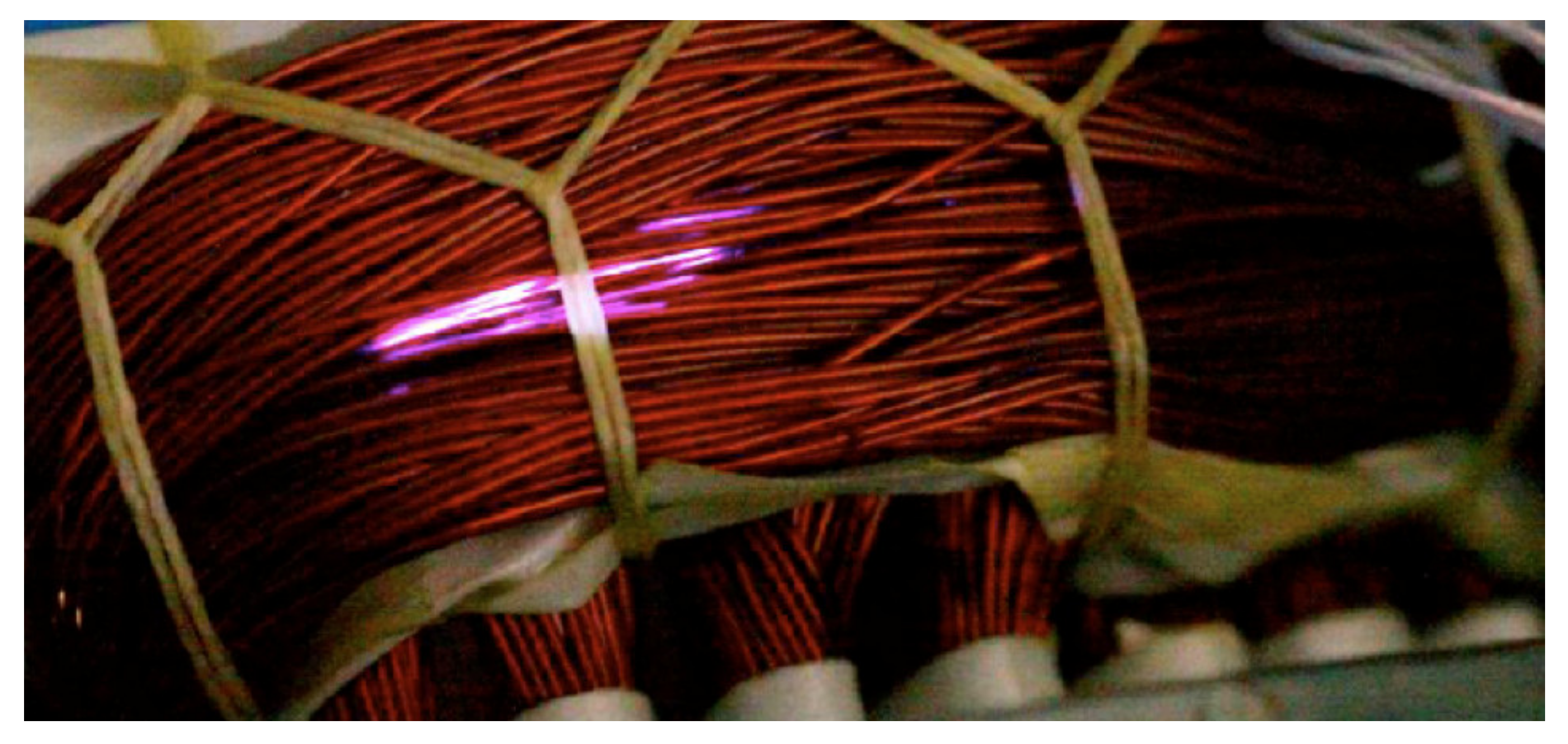
97]. With the increasing number of inverter-fed motors, new stresses have appeared concerning the high dV/dt switches (typically above 1 kV/μs). The associated over-voltage can reach twice the nominal voltage, which results in an acceleration in the insulation material degradation. These phenomena is usually accompanied by a glowing light (see
Figure 25), which is mainly visible at the end winding, especially when the over-voltage is the largest and the turns insulation is the weakest. In order to decrease the risk of insulation breakdown, different studies have been reported to detect PD activity specially in random wound motors [
98,
99].
6.6. Automated Production and Manufacturability
In big scale production, automated coil forming is a highly recommended procedure for the manufacturing of the electrical machine windings. Unlike the manual-made coil, the machine-made one has a final neat shape and is more compatible with the slot area as showcased in
Figure 26 [
100]. This process differs from one machine to the other based on the type of the magnet wire and the shape of the slot. With the different flexibility of magnet wires, the coil can be formed with controlled turn positioning, others are placed randomly inside the slot, since it is hard to control the strand position inside the slot.
In terms of the slot shape, an example to demonstrate is the hairpin windings. Such coils can be easily used with a semi-closed or even closed slot design by axial insertion of conductors. However, a post-process of welding will be required to connect the hairpins. This type of process can be very time consuming specially with a high number of slots and conductors per slot. In order to avoid the welding process, a radially-inserted hairpin with a continuous conductor can be used. However, an open slot design will be necessary. The main disadvantage of hairpin conductors includes the less flexibility of winding configuration inside different slot shapes. That is due to the fact that the parallel sided slot shape is the only compatible shape, unlike stranded wires which can fill any slot shape such as a trapezoidal slot. All of the aforementioned challenges associated with the manufacturing of hairpin windings are explained in details in [
101,
102].
In [
103], an alternative production process for windings of electrical machines is presented. Typically, the insertion of windings occurs in a slotted core structure of laminated soft magnetic material. Unlikely, the windings are assembled before the core is produced. However, this can be accomplished in powder core machines [
104,
105]. Interestingly, in such machines, the coils are firstly manufactured, then an iron powder core is added by molding compression. Therefore, certain specifications are required when a coil is produced. This includes low dimensional tolerances and high geometric accuracy. An example is demonstrated in
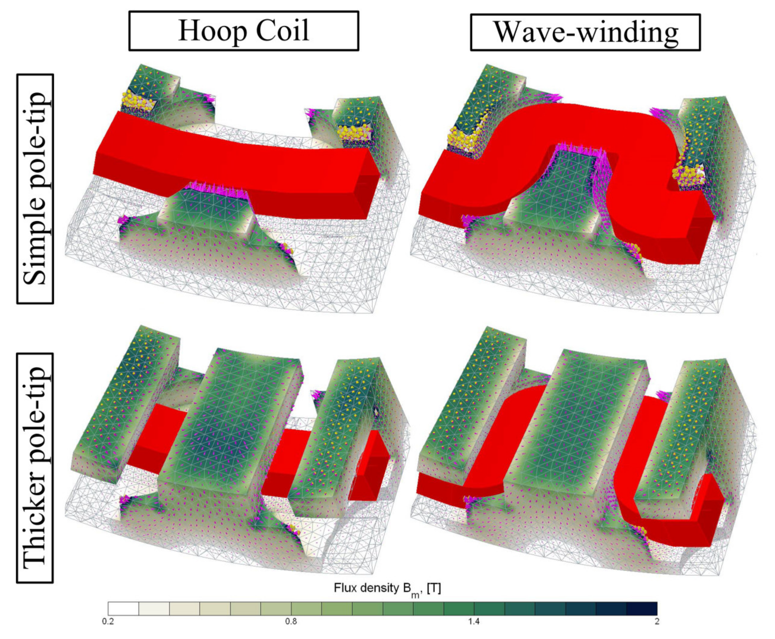
Figure 27 of continuous wave-windings shaped in a ring of rectangular copper wires for a powder-core claw pole machine. The performance of these coils is compared with the conventional hoop coils for a claw pole machine with different pole-tip thickness as shown in
Figure 28. It was found that the wave winding design has increased the flux linkage by nearly 50% compared to the claw pole with a hoop coil.
7. Conclusions
This paper provides a state-of-the-art review about different multi-physic design aspects associated with the manufacturing of electrical machine windings. Such aspects include the electromagnetic properties, thermal performance, and mechanical and noise problems. Many studies are compared and summarized more than any other previous work, offering a quick and comprehensive reference to the readers for a better selection of a suitable winding topology.
Material engineering of the different conducting materials have been overviewed. Moreover, this study provides new insights of the latest advancements in the field of additive manufacturing. Also, recent trends and progress of multi-material printing and integrated cooling channels are presented for better electrothermal performance.
Finally, different challenges are introduced that account for high frequency loss mitigation, mechanical and acoustic considerations, thermal management, partial discharge, insulation aging, and winding manufacturability. It is expected that new research studies will continue to push for more dense, reliable, and efficient electrical machines specially with the emergence of new manufacturing techniques such as 3D printing.
Author Contributions
A.S.; methodology, A.S., M.N.I. and P.S.; software, A.S.; investigation, A.S., M.N.I. and P.S.; resources, A.S., M.N.I. and P.S.; data curation, A.S.; writing—original draft preparation, A.S.; writing—review and editing, M.N.I. and P.S.; visualization, M.N.I. and P.S.; supervision, P.S.; project administration, P.S.; funding acquisition, M.N.I. and P.S. All authors have read and agreed to the published version of the manuscript.
Funding
This research is financially supported by the Research Foundation—Flanders (FWO) in the project (S001721N) entitled Multi-Material Additive Manufacturing for Electrical Machines with increased performance (AM4EM).
Conflicts of Interest
The authors declare no conflict of interest.
Appendix A
Table A1 shows different materials for film insulation classified based on their thermal class [
56].
Table A2 shows different materials for tap and fiber insulation classified based on their thermal class [
56].
Table A1.
Classification of film insulation based on their thermal class [
56].
Table A1.
Classification of film insulation based on their thermal class [
56].
| Film Insulation | Thermal Class & NEMA Standard | Pros and Cons |
|---|
| Polyvinyl Formal | Class 105 °C
MW15 | (+) Excellent abrasion resistance and compatibility with transformer oils (+) Good electrical properties • Used in Cryogenic applications
(−) Must be stripped before soldering (−) Should be annealed before application of varnish |
| Polyurethane | Class 155 °C
MW79
Class 180 °C
MW82 | (+) Excellent electrical properties for high “Q” coils. (+) Easily solderable at 390 °C/360 °C (+) Excellent film adhesion and flexibility (+) Good moisture and chemical resistance
(−) Not recommended for applications with the possibility of severe thermal overload |
| Polyurethane-Nylon | Class 155 °C
MW80
Class 180 °C
MW83 | (+) Good electrical properties (+) Easily solderable at 430 °C/390 °C (+) Excellent film adhesion and flexibility (+) Improved chemical and mechanical resistance from nylon overcoat
(+) Nylon overcoat provides low coefficient of friction
(−) Not recommended for applications with the possibility of severe thermal overload (−) Nylon overcoat is hygroscopic |
| Solderable Polyester | Class 180 °C
MW77 | (+) Solderable at 470 °C (+) Excellent thermal properties (+) Good electrical properties and moisture resistance (+) Good compatibility with varnishes and solvents (+) Improved thermal overload
(−) Low abrasion resistance compared to Nylon and Amide-Imide overcoat materials
(−) Preheat before varnishing is recommended |
| Solderable Polyester Nylon | Class 180 °C
MW78 | (+) Solderable at 470 °C (+) Excellent thermal properties (+) Good electrical properties and compatibility with varnishes and solvents (+) Improved thermal overload (+) Good moisture resistance (+) Nylon overcoat provides low coefficient of friction
(−) Nylon overcoat is hygroscopic (−) Preheat before varnishing is recommended |
| Polyester Amide-Imide | Class 200 °C
MW74 | (+) Excellent flexibility and abrasion resistance (+) Excellent thermal overload and moisture resistance (+) Superior dielectric strength (+) Good chemical resistance (−) Not recommended for use in oil-filled power and distribution transformers
(−) Must be stripped before soldering (−) Preheat before varnishing |
| Polyester/Poly Amide-Imide Overcoat | Class 200 °C
MW35 | (+) Excellent flexibility and abrasion resistance (+) Excellent thermal overload and moisture resistance (+) Superior dielectric strength (+) Good chemical resistance
(−) Must be stripped before soldering (−) Preheat before varnishing |
| Polyimide Class | Class 240 °C
MW16 | (+) Excellent flexibility (+) Excellent thermal overload and radiation resistance (+) Excellent chemical compatibility (+) High dielectric strength (+) Adequate abrasion resistance (+) Low outgas
(−) Must be stripped before soldering (−) Must be annealed before varnishing (−) Will solvent craze |
Table A2.
Classification of tap and fiber insulation based on their thermal class [
56].
Table A2.
Classification of tap and fiber insulation based on their thermal class [
56].
| Tape Insulation | Max. Temperature | Pros and Cons |
|---|
| Polyester (PET) Mylar (Heat sealable grades available) | 135 °C | (+) High dielectric strength (+) Good abrasion resistance (+) often used as binder or barrier under extruded jackets and textile serves or braids |
| Nomex, (aromatic polyamide) | 200 °C (Up to 220 °C in special applications) | (+) Excellent thermal properties (+) Excellent electrical properties (+) Excellent compatibility with varnishes, adhesives and transformer fluids (+) Thinner grades are flexible • Good resistance to tearing and abrasion |
| Polyimide Kapton (Heat sealable & adhesive grades available) | 240 °C (Up to 400 °C in special applications) | (+) Very high dielectric strength (+) Very good chemical resistance (+) Excellent mechanical properties |
| Fiberglass Cloth | determined by application and glass type | (+) Excellent electrical properties at high temperatures (+) Conformable (+) Varnish compatible grades available (+) Excellent solvent resistance |
| Mica | determined by application and glass type | (+) Excellent electrical properties at high temperatures (+) Flame resistant (+) Retains useful electrical properties during and after exposure to fire |
| Fiber insulation | Max. Temperature | Pros and Cons |
| Cotton | 135 °C | (+) Low cost serving (+) Good resistance to abrasion (−) Poor space factor compared to Nylon or Polyester (−) Non-solderable |
| Nylon | 155 °C | (+) Good space factor (+) Excellent abrasion resistance (+) Solderable (−) Hygroscopic |
| Dacron (Polyester) | 155 °C | (+) Good abrasion resistance (+) Solderable (+) Slightly higher maximum operating temperature than Nylon (+) Better space factor than Cotton or Glass (−) poorer space factor than Nylon |
| Nomex (High Temperature Nylon) | 250 °C | (+) Good space factor (+) Good electrical properties at high temperatures (−) Non-solderable (−) Higher cost than other fibers |
| Glass | 260 °C | (+) Good electrical properties at high temperatures (−) Space factor equivalent to Cotton (−) Non-solderable |
References
- Ramesh, P.; Lenin, N.C. High Power Density Electrical Machines for Electric Vehicles—Comprehensive Review Based on Material Technology. IEEE Trans. Magn. 2019, 55, 0900121. [Google Scholar] [CrossRef]
- Gerada, D.; Mebarki, A.; Brown, N.L.; Gerada, C.; Cavagnino, A.; Boglietti, A. High-Speed Electrical Machines: Technologies, Trends, and Developments. IEEE Trans. Ind. Electron. 2014, 61, 2946–2959. [Google Scholar] [CrossRef]
- Golovanov, D.; Papini, L.; Gerada, D.; Xu, Z.; Gerada, C. Multidomain Optimization of High-Power-Density PM Electrical Machines for System Architecture Selection. IEEE Trans. Ind. Electron. 2018, 65, 5302–5312. [Google Scholar] [CrossRef]
- Palka, R.; Wardach, M. Design and Application of Electrical Machines. Energies 2022, 15, 523. [Google Scholar] [CrossRef]
- Groschup, B.; Nell, M.; Pauli, F.; Hameyer, K. Characteristic Thermal Parameters in Electric Motors: Comparison between Induction- and Permanent Magnet Excited Machine. IEEE Trans. Energy Convers. 2021, 36, 2239–2248. [Google Scholar] [CrossRef]
- CME Group Inc. Copper Supply and Demand Dynamics. Available online: https://www.cmegroup.com/trading/metals/base/copper.html (accessed on 10 June 2022).
- Selema, A.; Ibrahim, M.N.; Sergeant, P. Mitigation of High-Frequency Eddy Current Losses in Hairpin Winding Machines. Machines 2022, 10, 328. [Google Scholar] [CrossRef]
- Sullivan, C.R. Aluminum Windings and Other Strategies forHigh-Frequency Magnetics Design in anEra of High Copper and Energy Costs. IEEE Trans. Power Electron. 2008, 23, 2044–2051. [Google Scholar] [CrossRef]
- Wojda, R.; Galigekere, V.P.; Pries, J.; Onar, O. Copper-Clad Aluminum Windings as an Alternative Conductor for High-Power Electric Vehicle Wireless Charging. In Proceedings of the 2020 IEEE Transportation Electrification Conference & Expo (ITEC), Chicago, IL, USA, 23–26 June 2020; pp. 1197–1200. [Google Scholar]
- Fengshun, W.; Yanxiang, H.; Yiping, W.; Bing, A.; Jinsong, Z. A study of thermosonic gold wire bonding onto silver plated copper pad. In Proceedings of the 2005 6th International Conference on Electronic Packaging Technology, Shenzhen, China, 30 August–2 September 2005; pp. 372–376. [Google Scholar]
- Zouzou, N.; Dang, T.T.; Duchesne, S.; Velu, G.; Ninet, O. Modeling and Experimental Characterization of Nickel-Coated Copper Wires for the Design of Extremely High-Temperature Electrical Machines. IEEE Trans. Magn. 2020, 56, 1–9. [Google Scholar] [CrossRef]
- Sasimurugan, T.; Palanikumar, K. Experimental studies on machining characteristics of hybrid aluminium metal matrix composite and carbon nano tubes added hybrid aluminium metal matrix composite. In Proceedings of the International Conference on Nanoscience, Engineering and Technology (ICONSET 2011), Chennai, Tamilnadu, 28–30 November 2011; pp. 159–162. [Google Scholar]
- Pyrhönen, J.; Montonen, J.; Lindh, P.; Vauterin, J.J.; Otto, M. Replacing Copper with New Carbon Nanomaterials in Electrical Machine Windings. Int. Rev. Electr. Eng. 2015, 10, 12. [Google Scholar] [CrossRef] [Green Version]
- Rallabandi, V.; Taran, N.; Ionel, D.M.; Eastham, J.F. Coreless multidisc axial flux PM machine with carbon nanotube windings. In Proceedings of the 2016 IEEE Conference on Electromagnetic Field Computation (CEFC), Miami, FL, USA, 13–16 November 2016; p. 8102904. [Google Scholar]
- Subramaniam, C.; Yamada, T.; Kobashi, K.; Sekiguchi, A.; Futaba, D.N.; Yumura, M.; Hata, K. One hundred fold increase in current carrying capacity in a carbon nanotube–copper composite. Nat. Commun. 2013, 4, 2202. [Google Scholar] [CrossRef] [Green Version]
- National Institute of Standards and Technology, U.S.D. of C. GE Electrical Machines-Enabling Technologies. Available online: https://www.nist.gov/system/files/documents/pml/high_megawatt/EL-Refaie-GE-AMO-Worshop-Presentation-9_8_2015.pdf (accessed on 10 June 2022).
- U.S. Department of Energy Metal (Cu, Al) CNT Composite Wires for Energy Efficient Motors. Available online: https://www.energy.gov/eere/amo/downloads/metal-cu-al-cnt-composite-wires-energy-efficient-motors (accessed on 10 June 2022).
- Energy, U.S.D. of Nanometal-Interconnected Carbon Conductors (NICCs) for Advanced Electric Machines. Available online: https://www.energy.gov/sites/prod/files/2017/12/f46/NanometalInterconnectedCarbonConductorsforAdvancedElectricMachines.pdf (accessed on 10 June 2022).
- Yanamoto, T.; Izumi, M.; Umemoto, K.; Oryu, T.; Murase, Y.; Kawamura, M. Load Test of 3-MW HTS Motor for Ship Propulsion. IEEE Trans. Appl. Supercond. 2017, 27, 5204305. [Google Scholar] [CrossRef]
- Fukuda, S.; Yun, K.; Iwakuma, M.; Miura, S.; Sato, S.; Yoshida, K.; Tomioka, A.; Konno, M.; Izumi, T. Design Study of 2-MW Fully Superconducting Synchronous Motors. IEEE Trans. Appl. Supercond. 2018, 28, 5207806. [Google Scholar] [CrossRef]
- Ikeda, K.; Nakamura, T.; Karashima, T.; Nishino, R.; Yoshikawa, M.; Itoh, Y.; Terazawa, T. DC and AC Current Transport Characteristics of the HTS Stator Coils in an HTS Induction/Synchronous Motor. IEEE Trans. Appl. Supercond. 2018, 28, 5204005. [Google Scholar] [CrossRef]
- Nakamura, T.; Yoshikawa, M.; Ikeda, K.; Karashima, T.; Ogasa, T.; Nishino, R.; Itoh, Y.; Terazawa, T.; Furuse, M.; Fukui, S. Load Test and Variable Speed Control of a 50-kW-Class Fully Superconducting Induction/Synchronous Motor for Transportation Equipment. IEEE Trans. Appl. Supercond. 2019, 29, 5203005. [Google Scholar] [CrossRef]
- Karashima, T.; Nakamura, T.; Ikeda, K.; Nishino, R.; Yoshikawa, M.; Itoh, Y.; Terazawa, T. Improvement of the Variable Speed Controllability of a 20 kW Class High-Temperature Superconducting Induction/Synchronous Motor at No-Load Condition. IEEE Trans. Appl. Supercond. 2018, 28, 5204105. [Google Scholar] [CrossRef]
- Nakamura, T.; Itoh, Y.; Yoshikawa, M.; Nishimura, T.; Ogasa, T.; Amemiya, N.; Ohashi, Y.; Fukui, S.; Furuse, M. Tremendous Enhancement of Torque Density in HTS Induction/Synchronous Machine for Transportation Equipments. IEEE Trans. Appl. Supercond. 2015, 25, 5202304. [Google Scholar] [CrossRef] [Green Version]
- Ikeda, K.; Nakamura, T.; Karashima, T.; Amemiya, N.; Yoshikawa, M.; Itoh, Y.; Terazawa, T.; Ohashi, Y. Hysteretic Rotating Characteristics of an HTS Induction/Synchronous Motor. IEEE Trans. Appl. Supercond. 2017, 27, 5203205. [Google Scholar] [CrossRef]
- Dezhin, D.S.; Kovalev, K.L.; Verzhbitskiy, L.G.; Kozub, S.S.; Firsov, V.P. Design and Testing of 200 kW Synchronous Motor with 2G HTS Field Coils. IOP Conf. Ser. Earth Environ. Sci. 2017, 87, 032007. [Google Scholar] [CrossRef]
- Maeda, H.; Yanagisawa, Y. Recent Developments in High-Temperature Superconducting Magnet Technology (Review). IEEE Trans. Appl. Supercond. 2014, 24, 4602412. [Google Scholar] [CrossRef]
- Stenzel, P.; Dollinger, P.; Mihajlovic, D.; Richnow, J.; Franke, J.; Endisch, C. Needle winding for distributed round-wire-windings without the use of insulation disks. In Proceedings of the 2014 4th International Electric Drives Production Conference (EDPC), Nuremberg, Germany, 30 September–1 October 2014; pp. 1–7. [Google Scholar]
- Kikuchi, Y.; Miyamae, M.; Fukuda, Y.; Nagata, M.; Tuda, T.; Tsutsui, H.; Ikegami, T.; Sakurai, T.; Yamada, S.; Yoshimitsu, T. Partial discharge characteristics of twisted enameled magnet wires for inverter-fed random wound motors. In Proceedings of the Proceedings of 2011 International Symposium on Electrical Insulating Materials, Kyoto, Japan, 6–10 September 2011; pp. 125–127. [Google Scholar]
- Kim, H.-K.; Jung, J.-K.; Park, K.-Y.; Im, C.-H.; Jung, H.-K. Efficient Technique for 3-D Finite Element Analysis of Skin Effect in Current-Carrying Conductors. IEEE Trans. Magn. 2004, 40, 1326–1329. [Google Scholar] [CrossRef]
- Hamalainen, H.M.; Pyrhonen, J.J.; Puranen, J. Minimizing skin effect in random wound high speed machine stator. In Proceedings of the IEEE EUROCON, St. Petersburg, Russia, 18–23 May 2009; pp. 752–757. [Google Scholar]
- Zhao, Y.; Li, D.; Pei, T.; Qu, R. Overview of the rectangular wire windings AC electrical machine. CES Trans. Electr. Mach. Syst. 2019, 3, 160–169. [Google Scholar] [CrossRef]
- Solaris-Shop American Wire Gauge Conductor Size Table. Available online: https://www.solaris-shop.com/content/AmericanWireGaugeConductorSizeTable.pdf (accessed on 10 June 2022).
- Liu, Y. Rectangular conductor windings for electric motor with high performance and high production volume. Rebort Swed. Electromobility Cent. 2019, 10, 1–9. [Google Scholar]
- Yoney, Domenick, J.D.K. Chevrolet Bolt EV Traction Motor. Available online: https://insideevs.com/news/341631/chevrolet-bolt-ev-traction-motor-deep-dive-video (accessed on 10 June 2022).
- Lequesne, B. Electric Machines for Automotive Propulsion: History and Future. Available online: http://emotorseng.com/wp-content/uploads/2019/05/2019-05-keynote2.pdf (accessed on 10 June 2022).
- Ishigami, T.; Tanaka, Y.; Homma, H. Motor Stator With Thick Rectangular Wire Lap Winding for HEVs. IEEE Trans. Ind. Appl. 2015, 51, 2917–2923. [Google Scholar] [CrossRef]
- Soltani, M.; Nuzzo, S.; Barater, D.; Franceschini, G. Considerations on the Preliminary Sizing of Electrical Machines with Hairpin Windings. In Proceedings of the 2021 IEEE Workshop on Electrical Machines Design, Control and Diagnosis (WEMDCD), Modena, Italy, 8–9 April 2021; pp. 46–51. [Google Scholar]
- Wojda, R.P.; Kazimierczuk, M.K. Winding resistance of litz-wire and multi-strand inductors. IET Power Electron. 2012, 5, 257. [Google Scholar] [CrossRef]
- Sullivan, C.R. Cost-constrained selection of strand diameter and number in a litz-wire transformer winding. IEEE Trans. Power Electron. 2001, 16, 281–288. [Google Scholar] [CrossRef]
- Yi, X.; Yang, T.; Xiao, J.; Miljkovic, N.; King, W.P.; Haran, K.S. Equivalent Thermal Conductivity Prediction of Form-Wound Windings With Litz Wire Including Transposition Effects. IEEE Trans. Ind. Appl. 2021, 57, 1440–1449. [Google Scholar] [CrossRef]
- OSCO. UK Litz Wire. Available online: http://www.osco.uk.com/products/cable-litz-wire/litz-wire-winding-wire (accessed on 10 June 2022).
- New England Wire Why Preformed Litz Wire is Best for High Current Magnetic Devices. Available online: https://www.newenglandwire.com/why-preformed-litz-wire-is-best-for-high-current-magnetic-devices (accessed on 10 June 2022).
- New England Wire SHAPED Compacted Litz-Wire. Available online: https://www.newenglandwire.com/product/shaped-compacted-litz-wire (accessed on 10 June 2022).
- Wrobel, R.; Ayat, S.; Baker, J.L. Analytical methods for estimating equivalent thermal conductivity in impregnated electrical windings formed using Litz wire. In Proceedings of the 2017 IEEE International Electric Machines and Drives Conference (IEMDC), Miami, FL, USA, 21–24 May 2017; pp. 1–8. [Google Scholar]
- MS-Wire Magnet Wire Insulation Guide. Available online: https://www.iewc.com/userfiles/documents/products/mw/78/c_/16/_s/_s/pe/ci/fi/ca/mw78c_16_s_specification.pdf (accessed on 10 June 2022).
- New England Wire Litz Wire and Applications. Available online: https://newtcdn.s3.us-east-2.amazonaws.com/wp-content/uploads/2017/12/02144706/NEWT-Litz-Book_FINAL.pdf (accessed on 10 June 2022).
- KUK Orthocyclic Coils. Available online: https://www.wijdeven.com/en/products/orthocyclic-coils (accessed on 10 June 2022).
- O’Donnell, P. Report of Large Motor Reliability Survey of Industrial and Commercial Installations, Part I. IEEE Trans. Ind. Appl. 1985, 4, 853–864. [Google Scholar] [CrossRef]
- O’Donnell, P. Report of Large Motor Reliability Survey of Industrial and Commercial Installations, Part II. IEEE Trans. Ind. Appl. 1985, 23, 865–872. [Google Scholar] [CrossRef]
- Stone, I.G.C.; Culbert, E.A.; Boulter, H.D. Electrical Insulation for Rotating Machines: Design Evaluation Aging Testing and Repair; John Wiley Sons: Hoboken, NJ, USA, 2014; Volume 21. [Google Scholar]
- Benbouzid, M.E.H. Bibliography on induction motors faults detection and diagnosis. IEEE Trans. Energy Convers. 1999, 14, 1065–1074. [Google Scholar] [CrossRef]
- Stone, G.C. Advancements during the past quarter century in on-line monitoring of motor and generator winding insulation. IEEE Trans. Dielectr. Electr. Insul. 2002, 9, 746–751. [Google Scholar] [CrossRef]
- Awadallah, M.A.; Morcos, M.M. Application of AI tools in fault diagnosis of electrical machines and drives-an overview. IEEE Trans. Energy Convers. 2003, 18, 245–251. [Google Scholar] [CrossRef]
- Filippetti, F.; Franceschini, G.; Tassoni, C.; Vas, P. Recent developments of induction motor drives fault diagnosis using AI techniques. IEEE Trans. Ind. Electron. 2000, 47, 994–1004. [Google Scholar] [CrossRef]
- New England Wire Different Materials of Electrical Insulations. Available online: https://www.newenglandwire.com/litz-wire-film-insulations (accessed on 10 June 2022).
- Kielmann, V.E.M.; Frieder, O.S. Insulation System for Inverter-Fed Traction Motors with High Rated Voltages. Available online: https://www.vem-group.com/fileadmin/content/pdf/Download/Broschüren/Flyer_VEM-Sachsenwerk/vemodur_en.pdf (accessed on 10 June 2022).
- Mahr, A.; Kneidl, M.; Regler, J.; Franke, J. Process design and evaluation for the automation of interphase insulation for distributed windings. Procedia Manuf. 2021, 55, 226–231. [Google Scholar] [CrossRef]
- Grubic, S.; Aller, J.M.; Lu, B.; Habetler, T.G. A Survey on Testing and Monitoring Methods for Stator Insulation Systems of Low-Voltage Induction Machines Focusing on Turn Insulation Problems. IEEE Trans. Ind. Electron. 2008, 55, 4127–4136. [Google Scholar] [CrossRef] [Green Version]
- IEEE Standard, Revision of I.S. 43-2000—IEEE Recommended Practice for Testing Insulation Resistance of Rotating Machinery. Available online: https://ieeexplore.ieee.org/servlet/opac?punumber=6740 (accessed on 10 June 2022).
- Schump, D.E. Testing to assure reliable operation of electric motors. In Proceedings of the 37th Annual Conference on Petroleum and Chemical Industry, Houston, TX, USA, 10–12 September 1990; pp. 179–184. [Google Scholar]
- Ma, X.; Ma, X.; Yue, B.; Lu, W.; Xie, H. Study of aging characteristics of generator stator insulation based on temperature spectrum of dielectric dissipation factor. In Proceedings of the Proceedings of the 7th International Conference on Properties and Applications of Dielectric Materials (Cat. No.03CH37417), Nagoya, Japan, 1–5 June 2003; Volume 1, pp. 294–297. [Google Scholar]
- Selema, A.; Ibrahim, M.N.; Sergeant, P. Metal Additive Manufacturing for Electrical Machines: Technology Review and Latest Advancements. Energies 2022, 15, 1076. [Google Scholar] [CrossRef]
- Simpson, N.; Mellor, P.H. Additive manufacturing of shaped profile windings for minimal AC loss in gapped inductors. In Proceedings of the 2017 IEEE International Electric Machines and Drives Conference (IEMDC), Miami, FL, USA, 21–24 May 2017; pp. 1–7. [Google Scholar]
- Simpson, N.; North, D.J.; Collins, S.M.; Mellor, P.H. Additive Manufacturing of Shaped Profile Windings for Minimal AC Loss in Electrical Machines. IEEE Trans. Ind. Appl. 2020, 56, 2510–2519. [Google Scholar] [CrossRef] [Green Version]
- Selema, A.; Ibrahim, M.N.; Sergeant, P. Additively-Manufactured Ultra-Light Shaped-Profile Windings for HF Electrical Machines and Weight-Sensitive Applications. IEEE Trans. Transp. Electrif. 2022, 1. [Google Scholar] [CrossRef]
- Lorenz, F.; Rudolph, J.; Wemer, R. Design of 3D Printed High Performance Windings for Switched Reluctance Machines. In Proceedings of the 2018 XIII International Conference on Electrical Machines (ICEM), Alexandroupoli, Greece, 3–6 September 2018; pp. 2451–2457. [Google Scholar]
- Wohlers, C.; Juris, P.; Kabelac, S.; Ponick, B. Design and direct liquid cooling of tooth-coil windings. Electr. Eng. 2018, 100, 2299–2308. [Google Scholar] [CrossRef]
- GKN Powder Metallurgy How 3D Printing is Redefining Inductor Coil Production. Available online: https://www.gknpm.com/en/our-businesses/gkn-additive/how-3d-printing-is-redefining-inductor-coil-production (accessed on 10 June 2022).
- Wu, F.; EL-Refaie, A.M.; Al-Qarni, A. Additively Manufactured Hollow Conductors for High Specific Power Electrical Machines: Aluminum vs Copper. In Proceedings of the 2021 IEEE Energy Conversion Congress and Exposition (ECCE), Vancouver, BC, Canada, 10–14 October 2021; pp. 4397–4404. [Google Scholar]
- Jung, J.; Helm, A.; Liebold, J. Improved Efficiency of Electric Drives with Additively Manufactured Roebel Bar Windings. MTZ Worldw. 2021, 82, 54–58. [Google Scholar] [CrossRef]
- Burnand, G.; Araujo, D.M.; Koechli, C.; Perriard, Y. Validation by measurements of a windage losses model for very-high-speed machines. In Proceedings of the 2017 20th International Conference on Electrical Machines and Systems (ICEMS), Sydney, NSW, Australia, 11–14 August 2017; pp. 1–4. [Google Scholar]
- Tenconi, A.; Vaschetto, S.; Vigliani, A. Electrical Machines for High-Speed Applications: Design Considerations and Tradeoffs. IEEE Trans. Ind. Electron. 2014, 61, 3022–3029. [Google Scholar] [CrossRef]
- Burnand, G.; Thabuis, A.; Araujo, D.M.; Perriard, Y. Novel Optimized Shape and Topology for Slotless Windings in BLDC Machines. IEEE Trans. Ind. Appl. 2020, 56, 1275–1283. [Google Scholar] [CrossRef]
- Shabaz Motors—PM DC, BLDC, Servo, Stepper, Moving Coil. Available online: https://community.element14.com/technologies/industrial-automation-space/b/blog/posts/motors---pm-dc-bldc-servo-stepper-moving-coil (accessed on 27 June 2022).
- Van Damme, J.; Verkroost, L.; Vansompel, H.; De Belie, F.; Sergeant, P. A holistic DC link architecture design method for multiphase integrated modular motor drives. In Proceedings of the 2019 IEEE International Electric Machines & Drives Conference (IEMDC), San Diego, CA, USA, 12–15 May 2019; pp. 1593–1598. [Google Scholar]
- Mellor, P.; Wrobel, R.; McNeill, N. Investigation of Proximity Losses in a High Speed Brushless Permanent Magnet Motor. In Proceedings of the Conference Record of the 2006 IEEE Industry Applications Conference Forty-First IAS Annual Meeting, Tampa, FL, USA, 8–12 October 2006; Volume 3, pp. 1514–1518. [Google Scholar]
- Mellor, P.; Wrobel, R.; Salt, D.; Griffo, A. Experimental and analytical determination of proximity losses in a high-speed PM machine. In Proceedings of the 2013 IEEE Energy Conversion Congress and Exposition, Denver, CO, USA, 15–19 September 2013; pp. 3504–3511. [Google Scholar]
- Renner, N.J.; Lenz, J.D.; Yi, X.; Haran, K.S. Development of form-wound air-core armature windings for high-frequency electric machines. In Proceedings of the 2017 IEEE International Electric Machines and Drives Conference (IEMDC), Miami, FL, USA, 21–24 May 2017; pp. 1–8. [Google Scholar]
- Tan-Kim, A.; Lanfranchi, V.; Vivier, S.; Legranger, J.; Palleschi, F. Vibro-acoustic simulation and optimization of a claw-pole alternator. In Proceedings of the 2015 IEEE Energy Conversion Congress and Exposition (ECCE), Montreal, QC, Canada, 20–24 September 2015; pp. 5227–5232. [Google Scholar]
- Torregrossa, D.; Peyraut, F.; Fahimi, B.; M’Boua, J.; Miraoui, A. Multiphysics Finite-Element Modeling for Vibration and Acoustic Analysis of Permanent Magnet Synchronous Machine. IEEE Trans. Energy Convers. 2011, 26, 490–500. [Google Scholar] [CrossRef]
- Park, J.T.; Kim, K.C.; Lee, J.I. Calculation of the end winding force for electrical rotating machines. In Proceedings of the IEEE International Electric Machines and Drives Conference, Piscataway, NJ, USA, 1–4 June 2003; Volume 3, pp. 1640–1645. [Google Scholar]
- Huang, L.; Galopin, N.; Chadebec, O.; Meunier, G.; Bannwarth, B. A Numerical Approach Including the Winding Impact for Electrical Machine Vibration Analysis. In Proceedings of the 2019 22nd International Conference on the Computation of Electromagnetic Fields (COMPUMAG), Paris, France, 15–19 July 2019; pp. 1–4. [Google Scholar]
- Chen, Q.; Liang, D.; Gao, L.; Wang, Q.; Liu, Y. Hierarchical thermal network analysis of axial-flux permanent-magnet synchronous machine for electric motorcycle. IET Electr. Power Appl. 2018, 12, 859–866. [Google Scholar] [CrossRef]
- Boglietti, A.; Carpaneto, E.; Cossale, M.; Vaschetto, S.; Popescu, M.; Staton, D.A. Stator Winding Thermal Conductivity Evaluation: An Industrial Production Assessment. IEEE Trans. Ind. Appl. 2016, 52, 3893–3900. [Google Scholar] [CrossRef]
- Zhang, B.; Qu, R.; Wang, J.; Xu, W.; Fan, X.; Chen, Y. Thermal Model of Totally Enclosed Water-Cooled Permanent-Magnet Synchronous Machines for Electric Vehicle Application. IEEE Trans. Ind. Appl. 2015, 51, 3020–3029. [Google Scholar] [CrossRef]
- Li, G.; Ojeda, J.; Hoang, E.; Gabsi, M.; Lecrivain, M. Thermal–Electromagnetic Analysis for Driving Cycles of Embedded Flux-Switching Permanent-Magnet Motors. IEEE Trans. Veh. Technol. 2012, 61, 140–151. [Google Scholar] [CrossRef] [Green Version]
- Liu, M.; Sixel, W.; Sarlioglu, B.; Nellis, G. Influence of winding topologies and encapsulation materials on FSPM machine thermal performance. IET Electr. Power Appl. 2020, 14, 1604–1611. [Google Scholar] [CrossRef]
- Popescu, M.; Staton, D.A.; Boglietti, A.; Cavagnino, A.; Hawkins, D.; Goss, J. Modern Heat Extraction Systems for Power Traction Machines—A Review. IEEE Trans. Ind. Appl. 2016, 52, 2167–2175. [Google Scholar] [CrossRef]
- Sixel, W.; Liu, M.; Nellis, G.; Sarlioglu, B. Ceramic 3D Printed Direct Winding Heat Exchangers for Improving Electric Machine Thermal Management. In Proceedings of the 2019 IEEE Energy Conversion Congress and Exposition (ECCE), Baltimore, ML, USA, 29 September–3 October 2019; pp. 769–776. [Google Scholar]
- Sixel, W.; Liu, M.; Nellis, G.; Sarlioglu, B. Cooling of Windings in Electric Machines via 3-D Printed Heat Exchanger. IEEE Trans. Ind. Appl. 2020, 56, 4718–4726. [Google Scholar] [CrossRef]
- Madonna, V.; Giangrande, P.; Walker, A.; Galea, M. On the Effects of Advanced End-Winding Cooling on the Design and Performance of Electrical Machines. In Proceedings of the 2018 XIII International Conference on Electrical Machines (ICEM), Alexandroupoli, Greece, 3–6 September 2018; pp. 311–317. [Google Scholar]
- Madonna, V.; Walker, A.; Giangrande, P.; Serra, G.; Gerada, C.; Galea, M. Improved Thermal Management and Analysis for Stator End-Windings of Electrical Machines. IEEE Trans. Ind. Electron. 2019, 66, 5057–5069. [Google Scholar] [CrossRef]
- Vansompel, H.; Sergeant, P. Extended End-Winding Cooling Insert for High Power Density Electric Machines With Concentrated Windings. IEEE Trans. Energy Convers. 2020, 35, 948–955. [Google Scholar] [CrossRef]
- Billard, T.; Lebey, T.; Fresnet, F. Partial discharge in electric motor fed by a PWM inverter: Off-line and on-line detection. IEEE Trans. Dielectr. Electr. Insul. 2014, 21, 1235–1242. [Google Scholar] [CrossRef]
- Tavner, P.J. Review of condition monitoring of rotating electrical machines. IET Electr. Power Appl. 2008, 2, 215. [Google Scholar] [CrossRef]
- Gerada, C.; Galea, M.; Giangrande, P.; Sciascera, C. Lifetime Consumption and Degradation Analysis of the Winding Insulation of Electrical Machines. In Proceedings of the 8th IET International Conference on Power Electronics, Machines and Drives (PEMD 2016), Glasgow, UK, 19–21 April 2016; Institution of Engineering and Technology: London, UK, 2016; p. 5. [Google Scholar]
- Fabiani, D.; Montanari, G.C.; Contin, A. Aging acceleration of insulating materials for electrical machine windings supplied by PWM in the presence and in the absence of partial discharges. In Proceedings of the ICSD’01 20001 IEEE 7th International Conference on Solid Dielectrics (Cat. No.01CH37117), Eindhoven, The Netherlands, 25–29 June 2001; pp. 283–286. [Google Scholar]
- Höpner, V.N.; Wilhelm, V.E. Insulation Life Span of Low-Voltage Electric Motors—A Survey. Energies 2021, 14, 1738. [Google Scholar] [CrossRef]
- Ayat, S.S. An Experiment-Informed Methodology for the Thermal Design of Permanent Magnet Electrical Machines. Ph.D. Thesis, University of Bristol, Bristol, UK, 2018. [Google Scholar]
- Glaessel, T.; Seefried, J.; Franke, J. Challenges in the manufacturing of hairpin windings and application opportunities of infrared lasers for the contacting process. In Proceedings of the 2017 7th International Electric Drives Production Conference (EDPC), Wuerzburg, Germany, 5–6 December 2017; pp. 1–7. [Google Scholar]
- Glaessel, T.; Pinhal, D.B.; Masuch, M.; Gerling, D.; Franke, J. Manufacturing Influences on the Motor Performance of Traction Drives with Hairpin Winding. In Proceedings of the 2019 9th International Electric Drives Production Conference (EDPC), Esslingen, Germany, 3–4 December 2019; pp. 1–8. [Google Scholar]
- Svensson, L.; Frogner, K.; Reinap, A.; Hogmark, C.; Alakula, M.; Andersson, M. Alternative production process for electric machine windings. In Proceedings of the 2012 2nd International Electric Drives Production Conference (EDPC), Nuremberg, Germany, 15–18 October 2012; pp. 1–7. [Google Scholar]
- Jack, A.G.; Mecrow, B.C.; Dickinson, P.G.; Stephenson, D.; Burdess, J.S.; Fawcett, J.N.; Evans, T. Permanent magnet machines with powdered iron cores and pre-pressed windings. In Proceedings of the Conference Record of the 1999 IEEE Industry Applications Conference. Thirty-Forth IAS Annual Meeting (Cat. No.99CH36370), Phoenix, AZ, USA, 3–7 October 1999; Volume 1, pp. 97–103. [Google Scholar]
- Reinap, A.; Hagstedt, D.; Hogmark, C.; Alakula, M. Evaluation of a semi claw-pole machine with SM2C core. In Proceedings of the 2011 IEEE International Electric Machines & Drives Conference (IEMDC), Niagara Falls, ON, Canada, 15–18 May 2011; pp. 248–253. [Google Scholar]
| Publisher’s Note: MDPI stays neutral with regard to jurisdictional claims in published maps and institutional affiliations. |
© 2022 by the authors. Licensee MDPI, Basel, Switzerland. This article is an open access article distributed under the terms and conditions of the Creative Commons Attribution (CC BY) license (https://creativecommons.org/licenses/by/4.0/).


