Article

Study on Structural Vibration Characteristics of L-Shaped Flexible Ring Gear and Establishment of System Coupling Vibration Model

1
School of Mechanical Engineering, Anhui University of Science and Technology, Huainan 232001, China
2
School of Mechanical Engineering, Northwestern Polytechnical University, Xi’an 710072, China
3
School of Mechanical Engineering, Yanshan University, Qinhuangdao 066004, China
4
College of Mechanical and Electrical Engineering, Nanjing University of Aeronautics and Astronautics, Nanjing 210016, China
5
School of Mechanical and Precision Instrument Engineering, Xi’an University of Technology, Xi’an 710048, China
*
Author to whom correspondence should be addressed.
Machines 2022, 10(5), 339; https://doi.org/10.3390/machines10050339
Submission received: 28 March 2022 / Revised: 18 April 2022 / Accepted: 20 April 2022 / Published: 6 May 2022
(This article belongs to the Section Machine Design and Theory)

Abstract

:
L-shaped flexible ring gear is a new solution to the non-uniform load distribution of planetary transmission systems. At present, the research on L-shaped flexible ring gear is still focused on its meshing characteristics and dynamic load sharing performance, and its structural vibration characteristics and dynamic coupling vibration characteristics with the system are not involved. Considering that the structural flexibility of the L-shaped flexible ring gear is significantly higher than that of the traditional ring gear, the structural vibration will obviously affect the load sharing and dynamic load factor performance of the transmission system, as well as the safety and reliability of the mechanism. Due to its strong structural flexibility and structural particularity, the existing dynamic analysis model is difficult to meet the requirements of analysis and design. In this paper, the coupling vibration model of L-shaped flexible ring gear planetary transmission systems is established, and the structural vibration characteristics of L-shaped flexible ring gear and its influence on the dynamic performance of the systems are deeply analyzed. The model foundation and theoretical guidance are provided for the design of L-shaped flexible ring gear and the analysis of the dynamic characteristics of flexible ring gear systems.

1. Introduction

As the most important index to measure the performance of a planetary transmission system, load-sharing performance is of great significance to the gear tooth strength, reliability design, and transmission stability of planetary transmission systems. However, due to the inevitable manufacturing error and installation errors, temperature changes in the working environment, component wear and elastic deformation and many other factors, the uneven load distribution and strong vibration of each branch of the system will lead to the abnormal operation of the planetary transmission system.
In order to obtain a planetary transmission system with excellent load sharing and dynamic load factor, many scholars have adopted a variety of methods to improve the load sharing performance and dynamic load performance of the planetary transmission system, such as setting the sun wheel and planet carrier as a floating mechanism, thin-wall ring gear, elastic support mode, lever linkage, tooth surface modification, etc. However, common methods to improve the load sharing performance of planetary transmission system are very limited and often have little effect.
Through theoretical analysis and experimental study, it was found that the influence of the flexibility of the ring gear on the dynamic characteristics of the system cannot be ignored [1,2,3,4,5,6,7,8]. Increasing the flexibility of the ring gear in the planetary transmission system will make the load distribution between the planetary gears more even. So, a thin-wall gear ring structure was proposed. Agusta Westland innovated the traditional ring gear by creatively using the L-shaped flexible ring gear planetary transmission system (as shown in Figure 1) in the helicopter’s main reducer, which greatly improves the ride, reliability and safety of the helicopter. Subsequently, the L-shaped flexible ring gear planetary transmission system has been popularized and applied in a variety of industrial equipment, but the related technology is still in the exploratory stage. Li Lei [9] analyzed the structural characteristics, meshing characteristics and load sharing performance of L-shaped flexible ring gear. The author [10,11] further explored the meshing characteristics, structural characteristics, load sharing and dynamic load factor performance of L-shaped flexible ring gear, and revealed the advantages and disadvantages of L-shaped flexible ring gear.
Most studies have focused on the meshing characteristics and load-sharing performance of L-shaped flexible ring gear, but the structural vibration characteristics and dynamic coupling vibration characteristics with the transmission system have not been involved. With the development of the aviation industry, the load of gear is increasing, the speed is getting higher and higher, and tends to be lightweight. As a result, many malignant accidents of fatigue rupture caused by excessive vibration of gear have occurred in transmission system at home and abroad in recent years. In addition, gear failure is sudden, hidden, and serious. That is, the accident is often a sudden occurrence, not found any precursor, and once the failure is very serious, gear fracture damage and power transmission will be interrupted. Therefore, it is necessary to fully consider and solve the causes of related faults in the design and development stage of gear. Considering that the structural flexibility of the L-shaped flexible ring gear is significantly higher than that of the traditional ring gear, the transmission system vibration caused by the vibration of the L-shaped flexible ring gear is bound to increase, making the vibration of the mechanism more complex and affecting the load sharing and dynamic load factor performance of the transmission system as well as the safety and reliability of the mechanism. In additional, the change of structural vibration of flexible ring gear will lead to the change of relative position of internal and external meshing gear pair along the meshing line direction, which will affect the tooth surface contact stress, dynamic meshing force, system load sharing and dynamic load performance, system vibration characteristics and operating conditions, etc. However, knowledge related to it is very scarce at present.
Considering that the existing transmission system dynamics simulation methods include concentrated mass method, finite element method and rigid-flexible coupling method, however, they all have certain limitations [12,13,14,15,16,17,18,19,20,21], as follows:
(a) Lumped mass method. The calculation accuracy is low and the flexibility and structural vibration of components cannot be taken into account.
(b) Finite element method. Due to the complexity of the transmission system structure, the finite element model will produce a large number of elements and nodes, which will seriously affect the speed and convergence of the solution, making it difficult to be applied in system dynamic.
(c) Rigid-flexible coupling method.
(1) Hertz contact theory is used to analyze the contact characteristics. It is difficult to obtain accurate results since rigid impact is used instead of gear meshing. The actual meshing characteristics of gears, including time-varying meshing stiffness, loaded transmission errors, meshing impact, and other internal excitations cannot be simulated by the software module mentioned above.
(2) The meshing stiffness provided by software is based on the theoretical value of standard gear. In real working conditions, the meshing stiffness will be affected by many factors, such as modification, structure, error, fault etc., presenting completely different characteristics from the theory. The theoretical value can not accurately express the actual meshing state of gear teeth.
(3) It is difficult for software to analyze component manufacturing error and installation error.
Therefore, this paper based on SIMPACK software and its secondary development technology, a rigid-flexible coupling model of the transmission system is established, which can accurately consider the dynamic excitation and structural vibration of the transmission system. This model solves the problems that the flexibility and structural vibration of each component cannot be accurately introduced when the lumped mass method is used in the existing literature, and the finite element method has a large amount of calculation and convergence difficulty, and avoids the problem that the rigid-flexible coupling model in the existing literature cannot accurately define the time-varying meshing stiffness of gears. The actual meshing state of gear teeth cannot be considered and the meshing force fluctuation caused by rigid contact exists. With the help of the improved coupling model created in this paper, the structural vibration characteristics of L-shaped flexible ring gear and its influence on the system vibration are deeply investigated, which provides an important reference for selecting and designing better flexible ring gear planetary gear train.

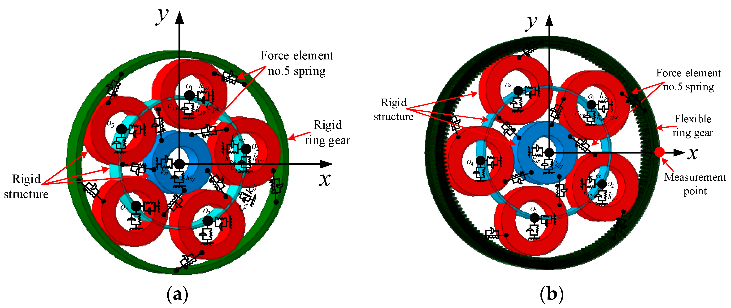
2. Modeling of Planetary Transmission System Coupled with Vibration of L-Shaped Flexible Structure and Rigid System

Considering that the structural compliance of the flexible ring gear is obviously higher than that of the traditional fixed ring gear, the system vibration caused by the structural vibration will inevitably increase. The vibration of the helicopter’s main reducer becomes more complex, affecting the load sharing and dynamic load performance of the transmission system and the safety and reliability of the helicopter. According to the shortcomings of the dynamics analysis methods, it is necessary to build a planetary transmission system simulation analysis model which can accurately consider all kinds of dynamic excitation of the system and realize the coupling between the vibration of the flexible structure and the vibration of the rigid body system. In addition, it can take into account various excitation such as time-varying meshing stiffness, loaded transmission errors, and meshing impact, so as to provide a tool for analyzing structural vibration characteristics of flexible ring gear and its influence on system dynamic characteristics. Therefore, this paper based on the existing rigid-flexible coupling software platform, the secondary development has successfully solved the shortcomings of the existing rigid-flexible coupling model. The real contact characteristics between gear teeth and various excitation of the system are introduced effectively, which provides technical support for analyzing vibration characteristics of flexible structure and its influence on dynamic characteristics of the system.

2.1. Steps for Building a Coupled Vibration Planetary Transmission System Model
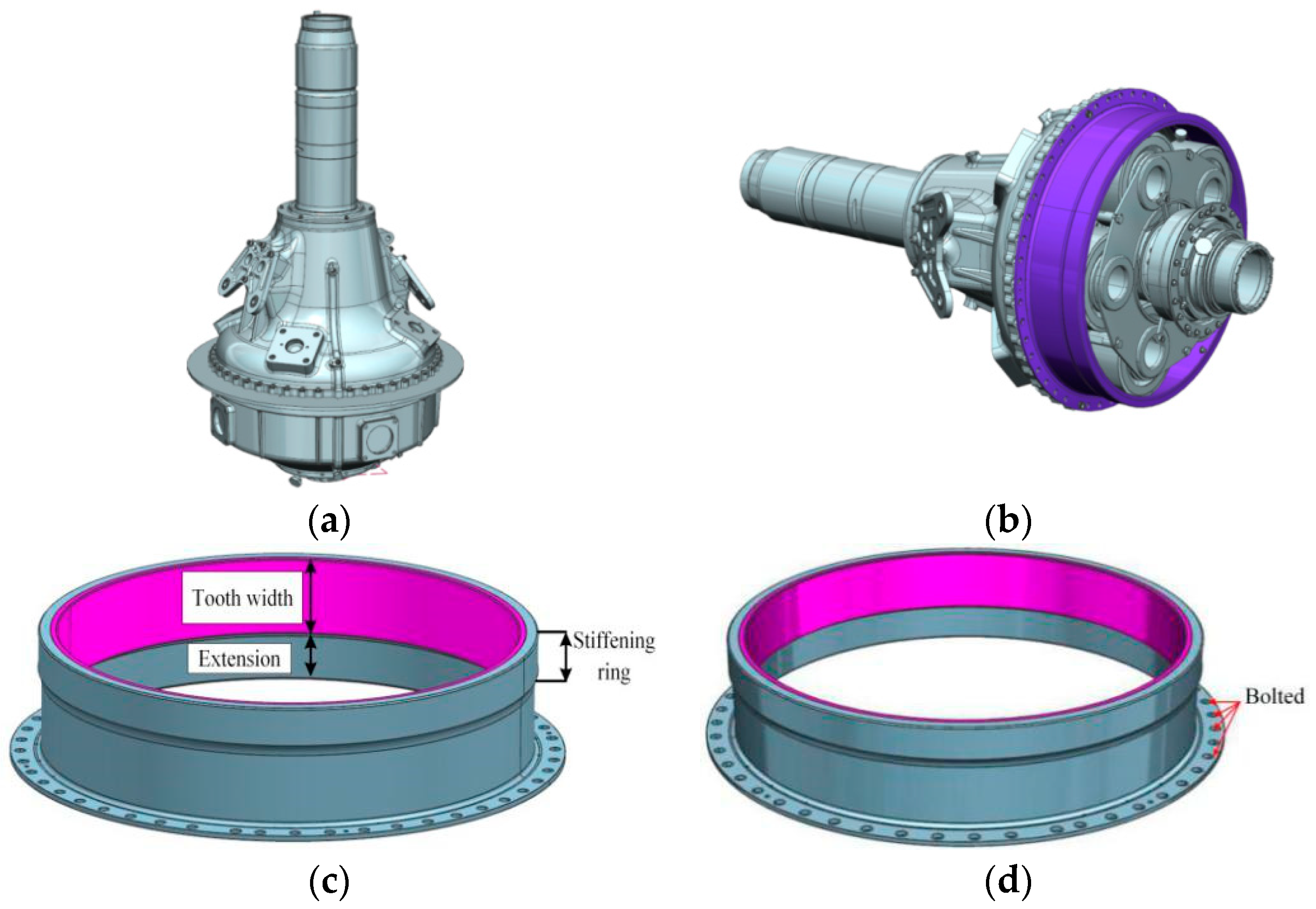
After considering the modeling ideas of various commercial software, SIMPACK, which adopts the relative coordinate modeling idea, is selected as the underlying software in this paper. SIMPACK is a multi-body dynamics software that uses the relative coordinate system to build models, which can describe and predict the kinematics and dynamics performance of complex mechanical systems, and analyze the vibration characteristics, stress status of the system, as well as the displacement, velocity and acceleration of parts.
The parameters of planetary transmission system in this paper are shown in Table 1.
The steps to create a planetary transmission system model coupled with structural vibration and system vibration are as follows:
(a) 
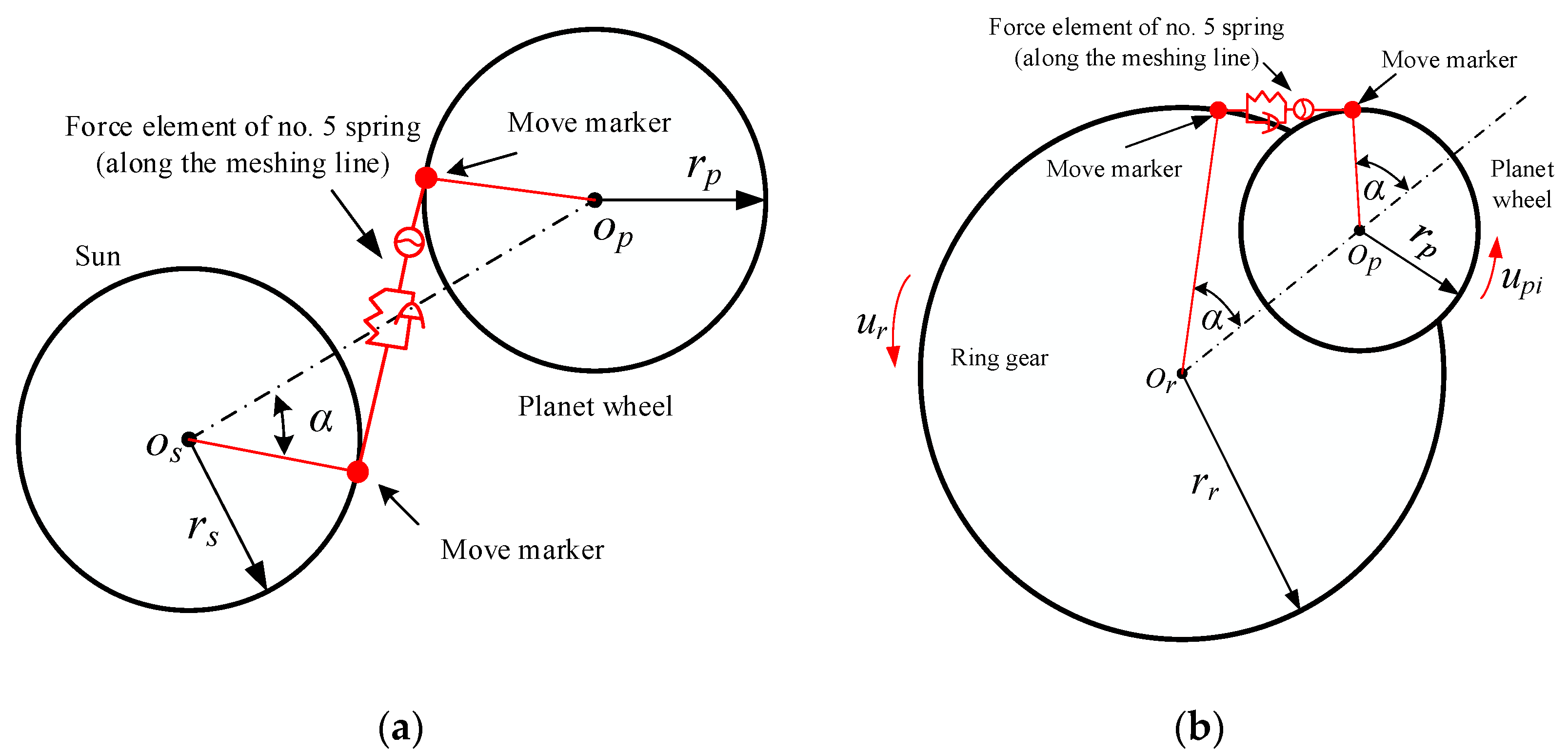
Determine the meshing line position of each internal and external meshing pairs
Since there are many pairs of internal and external meshing pairs in planetary transmission system, the positions of meshing lines and their included angles with coordinate axes are different. The position of meshing line of each internal and external gear pair is determined by determining the relative position relation of each internal and external gear pairs and the included angle relation with the coordinate axis.
(b) 
Set the time varying meshing unit and function relation
Loaded transmission errors is the angle difference between the gear pair deviating from the theoretical position under load. Loaded transmission errors includes both geometric transmission error and comprehensive loaded deformation of tooth surface (including bending deformation, shear deformation, contact deformation and deformation of tooth foundation). The comprehensive time-varying meshing stiffness refers to the comprehensive ability of all tooth pairs to resist tooth deformation during meshing. In this paper, by means of the LTCA model [22], the loaded transmission errors and comprehensive time-varying meshing stiffness of internal and external meshing pair in planetary transmission system can be obtained through analysis and calculation.
According to the meshing line position of each internal and external meshing pairs determined, the ‘move marker’ point between each internal and external meshing pairs is set (refer to Figure 2). The move marker point is the intersection point of meshing line and base circle, and the reference point of the move marker point is set as the joint point of each gear. Since the move marker point has the same rotation characteristic relative to the reference point, the motion relation of the gear pairs can be transformed to the meshing line. Then, the spring force element is set on the meshing line of each internal and external meshing gear pairs. According to the dynamics relationship between the internal and external meshing pairs and SIMPACK secondary development language. Write the input function of the spring force element between each internal and external gear pairs, and decompose the spring force element into the corresponding x axis and y axis according to the angle between the spring force element and the coordinate axis. In the figure, α represents the meshing angle; rs, rp, rr represent the radius of the base circle of the sun wheel, the planet wheel and the ring gear, respectively.
(c) 
Errors, loaded transmission errors and meshing impact are included
The error excitation and loaded transmission errors excitation in the internal and external gear pairs of each branch of the planetary transmission system can be introduced into the function relation by transforming them into along the meshing line. Specific transformation methods can be found in reference [22]. A new spring force element is needed for the meshing impact excitation. Fourier expansion is performed on the meshing impulse excitation and the resultant function is fitted. By writing the corresponding function relation, the introduction of the meshing impact excitation is realized.
(d) 
Other components
In addition, bearings, splines, and other components in the planetary transmission system can be introduced according to the actual working conditions, so as to enrich the whole simulation model and achieve more accurate analysis of the system. As this paper focuses on the flexible ring gear, it is not repeated here. So far, a rigid coupling simulation model of planetary transmission system can be established, which accurately considers the real meshing characteristics of ring gear.
(e) 
Create flexible body of ring gear
Firstly, the finite element model of ring gear is constructed and the main node of the ring gear is determined. The central point is usually taken as the main node, and the main node will be the point of transferring force and vibration with the sun wheel and planet wheel, so as to realize the transmission of interaction between the flexible ring gear and other rigid bodies. Then, the ring gear flexible body file (.fbi file) was obtained, and the original rigid ring gear of the planetary transmission system was replaced, so as to realize flexible processing of the model and obtain the rigid-flexible coupling model of the system, as shown in Figure 3b. So far, the planetary transmission system model was established, which could accurately consider the time varying meshing stiffness of internal and external gear pairs, errors, and the meshing impact.

2.2. Flexible Body Theory

The elastic deformation of the flexible body in the coupled model can’t be directly replaced by the traditional motion equation of the rigid body system, but the displacement u i ( x , t ) of the flexible body in the system can be expressed by the motion equation of an individual fixed reference frame. That is, coordinate y i ( t ) and small deformation w ( x , t ) are expressed as [23]:
u i ( x , t ) = y i ( t ) + w ( x , t )
The approximation of the lower mode of w ( x , t ) is:
w ( x , t ) j = 1 δ i q j i ( t ) w j i ( x )
In general, finite element analysis based on flexible body can select mode q j i ( t ) corresponding to the natural mode w j i ( x ) . Function w j i ( x ) is the characteristic mode, static mode, or frequency response mode in the frequency range. Through the development of this theory, the existing modal synthesis theory is obtained.
Modal synthesis theory is adopted to transform the displacement deformation of components subjected to external forces into linear superposition of components’ modes, so as to realize rigid-flexible coupling of the system. Modal synthesis is to decompose a complex structure into several simpler substructures. The vibration form of the whole structure is obtained by using the vibration form of each substructure. In order to solve the inherent characteristics of the system and analyze the dynamic response, only a few main modes (main modes) of the substructure need to be calculated. So, you can effectively reduce the degrees of freedom without changing the physical nature of the system.

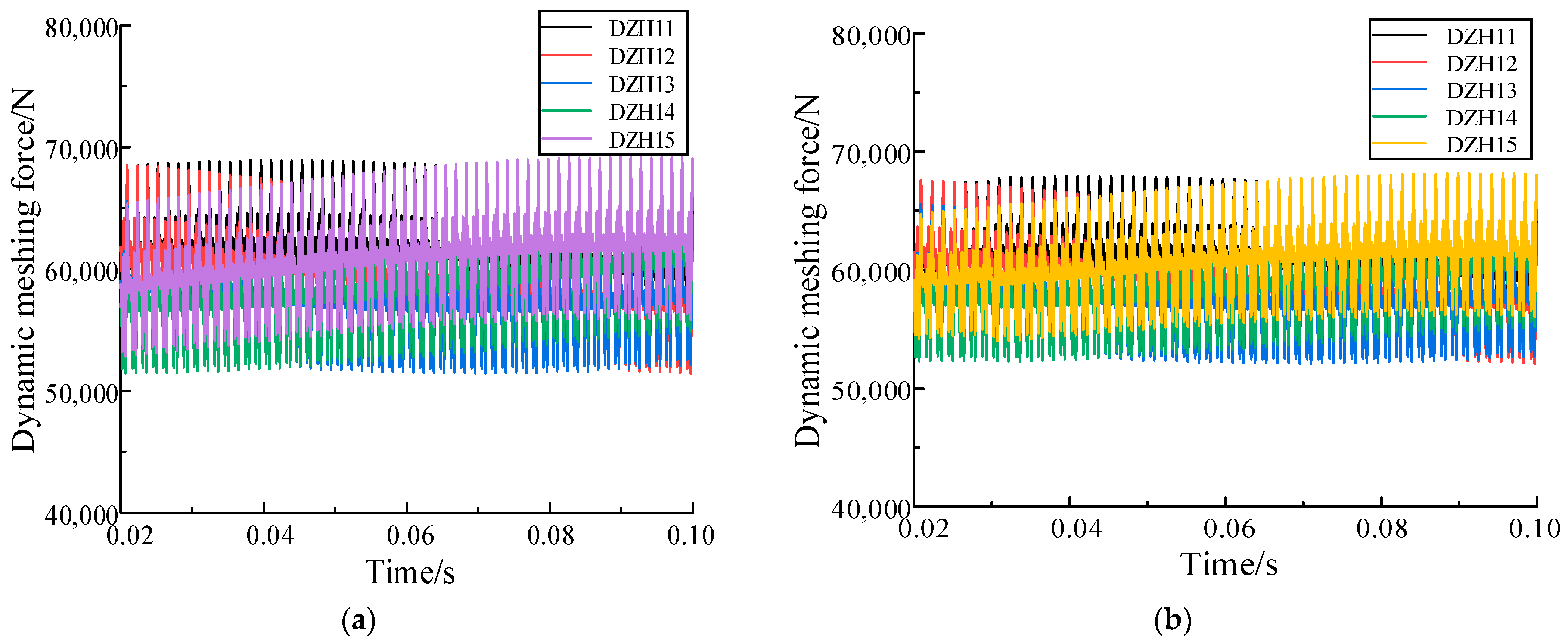
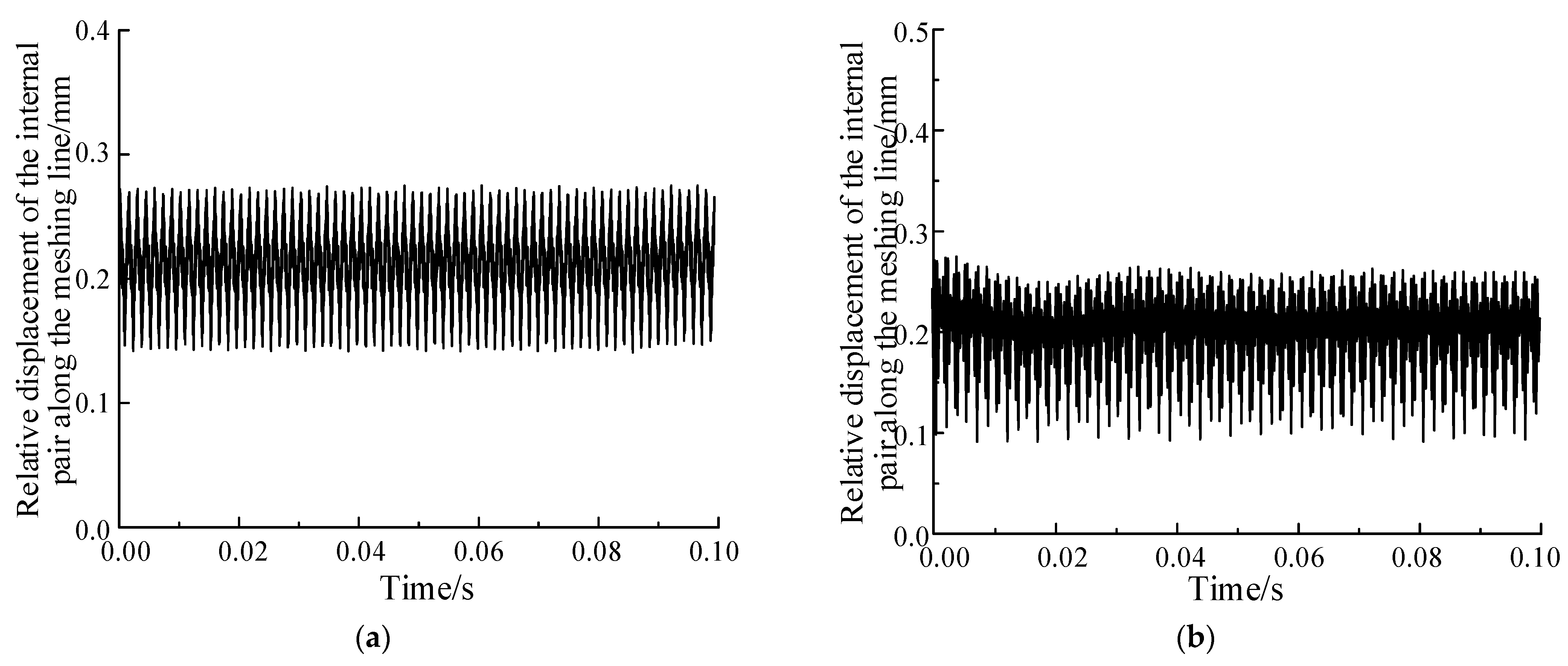
2.3. Comparison of Coupled Model and Lump Mass Method

In order to verify the accuracy of the coupling model, the dynamic meshing force of the system obtained by the rigid coupling model and the lumped mass method under the same working conditions and excitation is firstly compared in this paper.
The comparison between Figure 4 and Figure 5 shows that the dynamic meshing forces of all branches fluctuate sinusoidal function when the sun wheel (ring gear) of the system has errors, and the dynamic meshing forces of all branches are interrelated and meet the system balance. The mean and waveform of the simulation results obtained by the lumped mass method and rigid coupling model are basically consistent, which verifies the correctness of the proposed coupling model.
Then, the difference between the rigid-flexible coupling model and the lumped mass method is further compared to obtain the dynamic characteristics of the system before and after considering the comprehensive influence of the vibration mode of the flexible ring gear structure. Figure 6 shows the comparison of the relative displacement responses of the planetary wheel and the ring gear along the meshing line in the system before and after considering the flexibility of the L-shaped ring gear and the structural vibration at working speeds.
It can be seen from Figure 6 that the dynamic characteristics of the system change significantly after the structural vibration is taken into account. When the internal ring gear flexibility and structural vibration are not taken into account, the relative displacement fluctuation amplitude along the meshing line of the planetary transmission system is small and regular, and there is no irregular change, indicating that the transmission of the system is stable. When the flexibility and structural vibration of the ring gear are taken into account, the relative displacement mean value and fluctuation amplitude of the internal meshing pair along the meshing line of the system change obviously, and do not change completely regularly, which will have a great impact on the smoothness of planetary transmission system and affect the load sharing and dynamic load factor performance. Therefore, it is very important and necessary to fully consider the flexibility and vibration characteristics of the structure when analyzing the dynamic characteristics of the system. After the above analysis, the system response under the comprehensive influence of the vibration modes of each structure of the ring gear can be obtained, but the defect is that the characteristics of the vibration modes of each structure and their influence on the dynamic characteristics of the system cannot be further defined. Therefore, it is difficult to guide planetary transmission system design, which is also a problem existing in many literature analyses at present. In order to provide some reference for the structural design of flexible ring gear, an in-depth analysis of the vibration mode characteristics of each structure of ring gear and its influence on the dynamic characteristics of the system is carried out below.

3. Structural Vibration Characteristics of L-Shaped Flexible Ring Gear and Its Influence on System Dynamic Characteristics

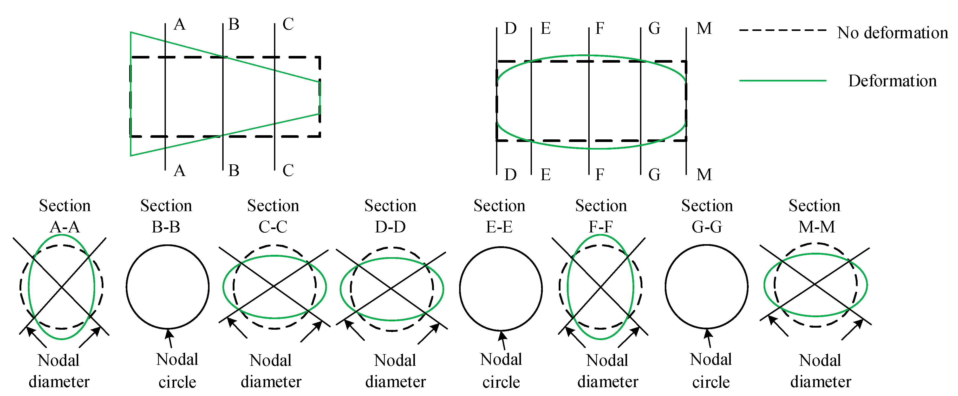
3.1. Type of Structural Vibration

For the ring gear, its macroscopic shape is thin-walled cylindrical. Its vibration mode is shown in Figure 7. There are three vibration modes: a nodal diameter type, nodal circle type, and a hybrid nodal diameter and nodal circle type. According to the number of nodal diameters and nodal circles, the vibration modes of each mode can be accurately judged as m nodal diameters or n nodal circles.
For the L-shaped flexible ring gear structure, the first 20 modes of natural vibration are obtained by using finite element software. The main natural vibration modes of L-shaped flexible ring gear and the main frequencies that may cause resonance under the operating conditions of the system are covered (Table 2). Subsequently, the types of modal natural modes were analyzed, and the analysis results are shown in Table 3.

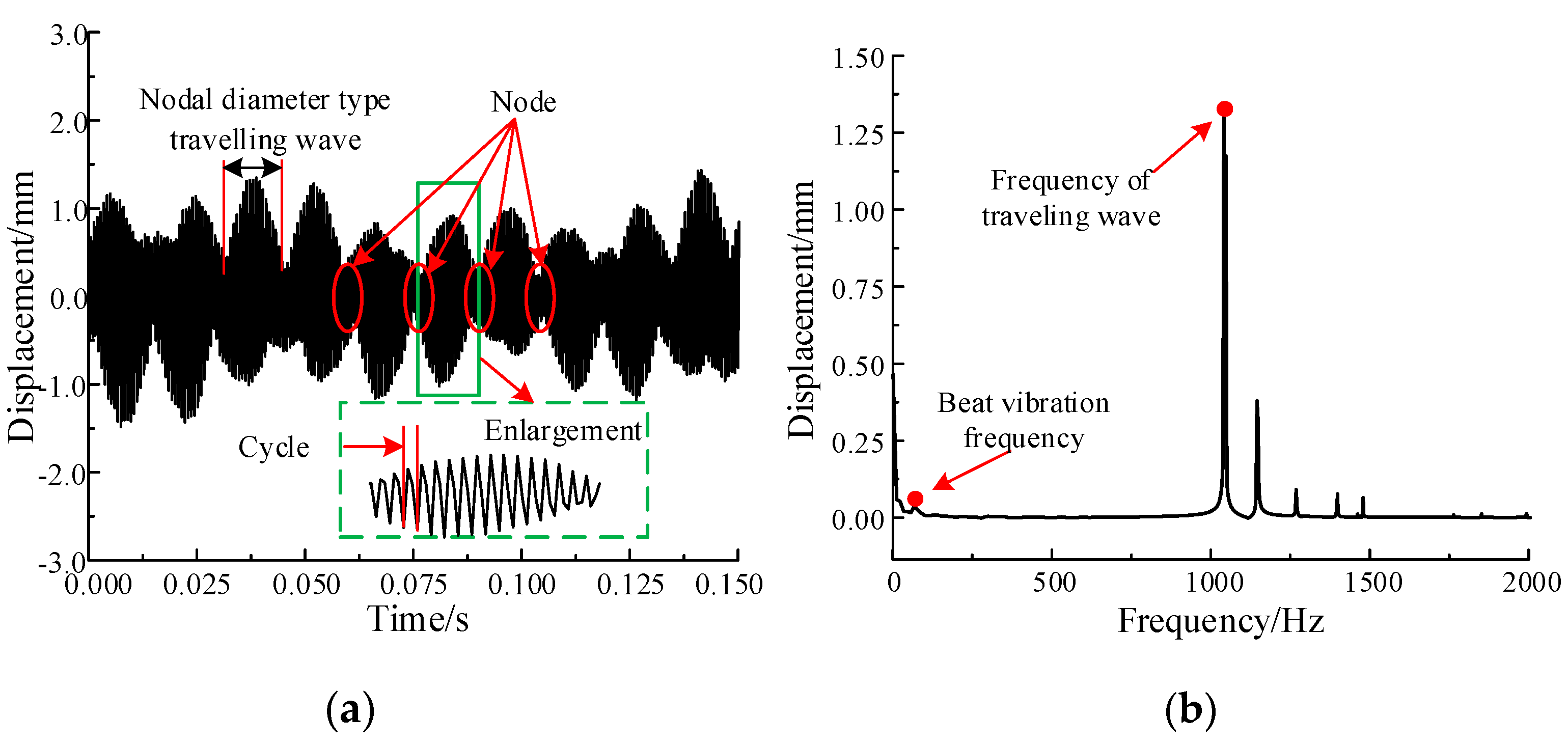
3.2. Characteristics of Nodal Diameter Vibration

From the point of view of gear failure, much of the damage of gear is caused by nodal diameter vibration. When the ring gear produces node diameter vibration, the radial displacement of each point can be expressed as [23]:
x = X ( r ) cos ( m θ ) cos ( p t )
where, x represents the radial displacement of each point; X(r) represents the amplitude of each point; m represents the number of nodal diameter; θ represents the circumference angle; p represents the circular frequency, f = p/2π; f represents the static frequency.
Expand the right side of Equation (3) according to the trigonometric series:
x = X ( r ) 2 [ cos ( m θ + p t ) + cos ( m θ p t ) ]
Xcos( + pt)/2 and Xcos(pt)/2 are called moving waves, that is, the vibration can always be decomposed into two traveling waves with the same frequency as the original vibration, half of the amplitude of the original vibration and opposite direction of motion. The position equation of nodal diameter is:
cos ( m θ ± p t ) = 0
θ = ± p t m + π 2 m
The time derivative of Equation (6) is obtained, and the rotational angular velocity of the corresponding traveling wave is:
θ ˙ = ± p m
When the gear is rotating at an angular speed of ωd, if the observer is rotating at the same speed, he will see a nodal line vibrating with respect to the wheel. It can also be considered as the superposition of two traveling waves with equal size and opposite propagation direction (one rotates in the same direction as the wheel, and the other rotates in the opposite direction) and the same angular velocity. If observed in the stationary coordinate, the two travelling waves should be superimposed with the angular velocity of the gear ωd in addition to their own rotational speed. In this case, the travelling waves before and after will no longer be equal.
θ ˙ = ± p d m + ω d
where, ωd represents the rotational angular velocity of the gear; p d represents circle frequency. Due to the effect of the mass centrifugal force of the inner gear ring itself, p d is generally slightly larger than p .
When the traveling wave rotates, the particle on the gear oscillates circumferentially with its position on the traveling wave. As the gear has m nodal diameters, it can be seen from the static coordinate that the particle on the gear vibrates circumferentially for m times. The gear vibration frequency can be obtained from the static coordinate by multiplying the number of nodal diameters by the traveling wave speed. That is:
m θ ˙ = ± p d + m ω d
m θ 2 π = ± p d 2 π + m ω d 2 π
f d = p d 2 π , ω d 2 π = N 60
The frequencies are all positive. Therefore, the natural frequencies of the before and after traveling wave vibration of the gear are:
f f = f d + m N / 60
f b = f d m N / 60
However, as the ring gear of 2K-H planetary transmission system adopted in this paper is a fixed part, ω d = 0 . Thus there are:
f f = f b = f d = f
where ff represents the natural frequency of the before wave vibration; fb represents the natural frequency of after traveling wave vibration; fd represents the moving frequency; and N indicates the speed of the gear. The above formula indicates the rotational speed of before wave and after wave is the same, and only one traveling wave vibration exists. Since the ring gear in the 2K-H planetary transmission system is a fixed part, the frequency of the before wave is equal to the after wave, and the dynamic frequency is equal to the static frequency. Therefore, the excitation frequency that can arouse the node diameter type traveling wave is the meshing frequency.
Table 4 shows the sun wheel input speed of the planetary transmission system when the nodal diameter type traveling wave resonance of the L-shaped flexible ring gear occurs. When the running speed is the same as the resonance speed, the corresponding nodal diameter type traveling wave vibration will be caused.
In order to understand the characteristics of nodal diameter type travelling wave vibration and its influence on the ring gear structure, with the help of rigid-flexible coupling vibration model, the input speed of the sun wheel was selected as 1752 rpm, which was close to the five nodal diameter travelling wave resonance speed. The variation of radial displacement response on the rim with time when traveling wave resonance occurred was obtained by solving the problem. The displacement response obtained is shown in Figure 8a.
The measuring point of displacement response on the rim of L-shaped flexible ring gear is shown in Figure 3b, which can accurately reflect the maximum displacement response generated on the rim when traveling wave resonance occurs.
As can be seen from Figure 8, at the resonance speed, the displacement response on the rim presents an obvious periodic vibration, which is characterized by beat vibration. Firstly, its radial vibration response is approximately simple harmonic vibration, and a fluctuation period of gear rotation is about 16 meshing cycles (when the load is applied for a cycle, the total number of traveling wave vibration cycles is equal to the teeth of the ring gear). Secondly, when the load is applied in a circle, the radial displacement response at the measured point has ten nodes, which is equivalent to the five nodal diameter resonance. The envelope of the maximum value is approximately a sine or cosine curve, which is in good agreement with the theoretical wave curve of the nodal diameter type vibration. In addition, when resonance occurs, the displacement response on the rim is significantly enhanced compared with the amplitude at the working speed, which will have a great impact on the structural vibration of the flexible ring gear, so the generation of traveling wave resonance should be avoided as far as possible.

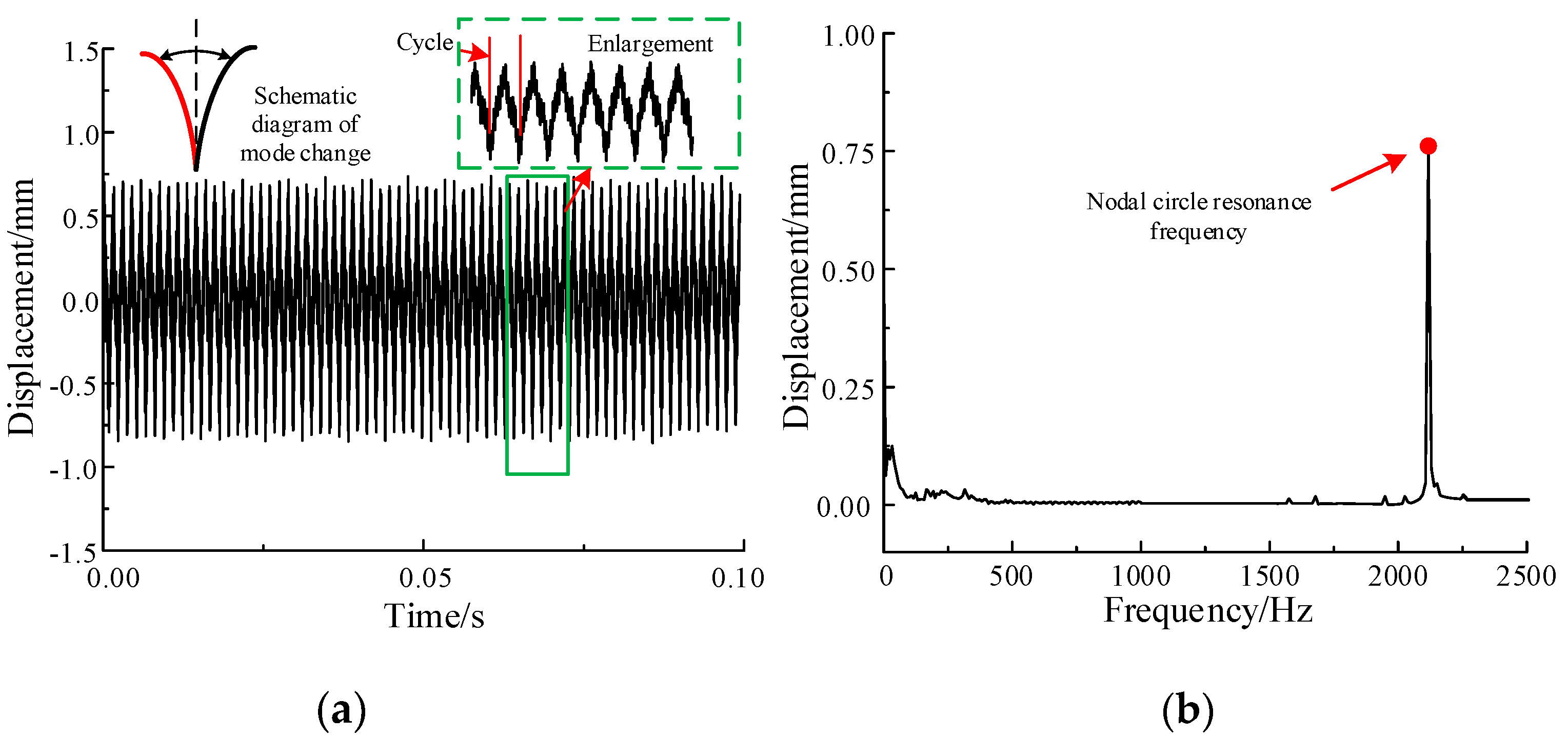
3.3. Analysis of Nodal Circle Vibration Characteristics

In order to understand the nodal circle vibration characteristics, the displacement response on rim with time of L-shaped flexible ring gear was obtained by referring to the same method of the previous section.
The selected input speed of the sun wheel is 3352 rpm, which is close to the resonant frequency of nodal circle on 2069 Hz. As can be seen from Figure 9, when the nodal circle resonance occurs, the displacement response on the rim is quite different from that of the nodal diameter resonance, and the displacement response on the rim is basically consistent in each meshing period without obvious beat vibration phenomenon. There is no vibration node, and the displacement response under each meshing period is regular. In addition, the nodal circle vibration is due to the axial expansion along the ring gear of the wave. Therefore, it does not produce the form of traveling wave vibration, and its axial wave form is mainly determined by the number of nodal circle modes generated. Therefore, the influence of meshing on transmission process is less than that of nodal diameter type vibration.

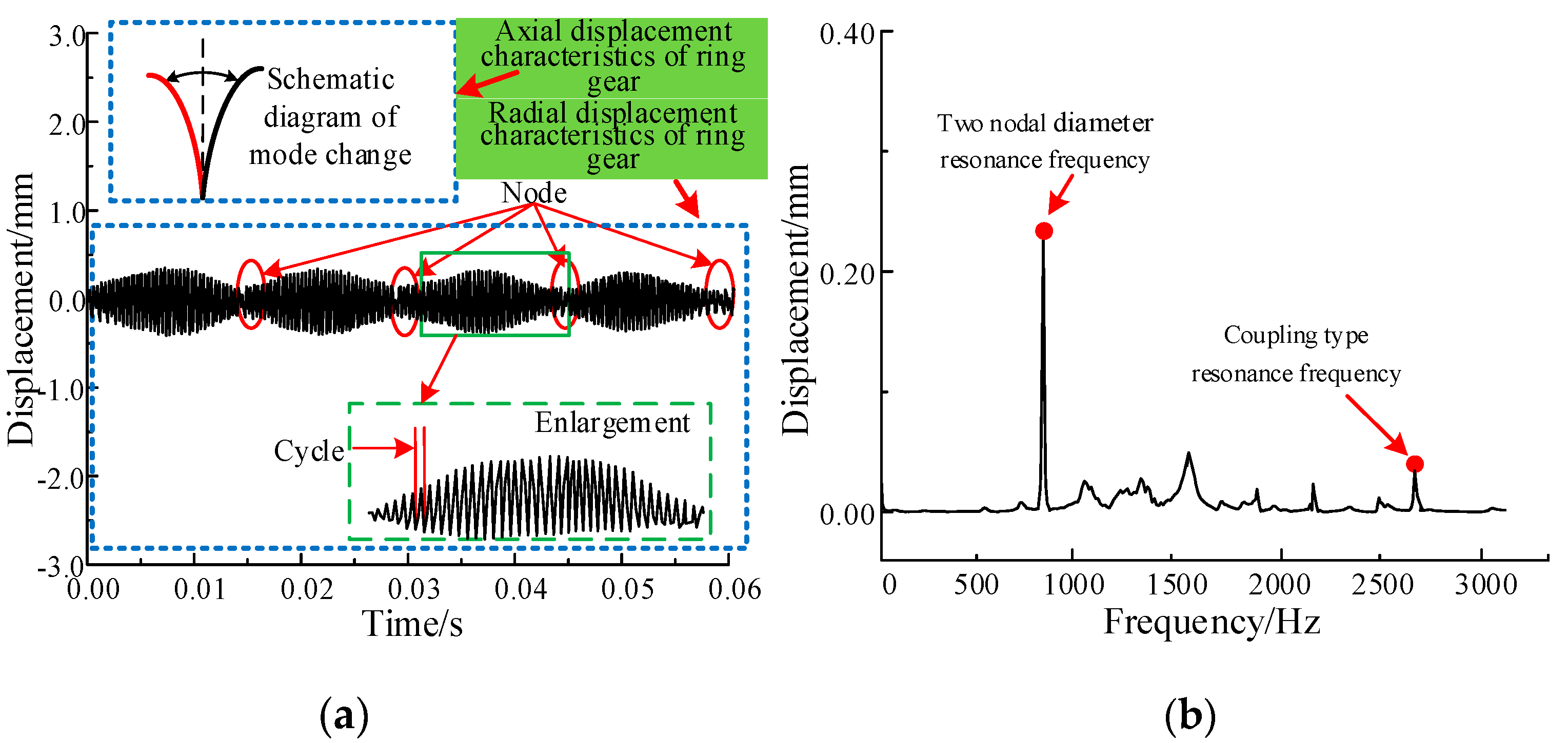
3.4. Analysis of Coupling Nodal Diameter and Nodal Circle Vibration Characteristics

The same method and measuring points are used to analyze the characteristics of coupling nodal diameter and nodal circle vibration. The radial displacement response of L-shaped flexible ring gear under coupling nodal diameter and nodal circle vibration is also obtained accurately. The displacement response obtained is shown in Figure 10. Here, for the L-shaped flexible ring gear, the input speed of the sun wheel is 4160 rpm. This speed corresponds to the meshing frequency of the L-shaped flexible inner gear ring at 2567.8 Hz, which is close to the resonant frequency of the coupling type. The displacement response obtained is shown in Figure 10a. As can be seen from Figure 10, when the coupling vibration of nodal diameter and nodal circle occurs, the coupling vibration mode of nodal diameter and nodal circle is a high order vibration mode. Therefore, when resonance occurs, it has little influence on the vibration of the structure. In addition, the coupling vibration is the superposition coupling of nodal diameter vibration and nodal circle vibration. The displacement response at the measuring point of the rim has the characteristics of the beat vibration, which can be clearly seen as the two nodal diameter travelling wave resonance.

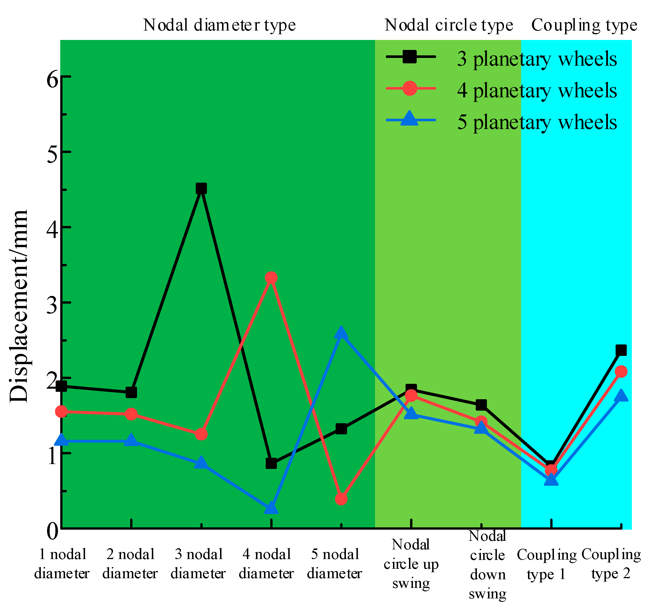
3.5. Relationship between Structural Modes and the Number of Planetary Wheels

The number of planetary wheels used in planetary transmission system is varied, but the correlation between the number of planetary wheels and the vibration of system structure is rarely studied. The analysis of the relationship between the number of planetary wheels and structural vibration can provide reference for the design of planetary transmission system. In this section, the L-shaped flexible ring gear planetary drive system is taken as an example, and the relationship between the number of planetary wheels and the structural vibration of ring gear is preliminarly analyzed and obtained. The specific results are shown in Table 5 and Figure 11 below.
The first five order nodal diameter vibration is the main vibration. Therefore, the first five steps of pitch shape vibration of L-shaped flexible ring gear are selected. At the same time, the nodal circle mode and coupling modes were added to solve and compare. In Figure 11, the maximum value comparison diagram of radial vibration displacement response of L-shaped flexible ring gear under three planetary wheels, four planetary wheels, and five planetary wheels is drawn, respectively.
According to the comparison, when the planetary transmission system adopts three planetary wheels, the vibration amplitude of the corresponding third nodal diameter mode is the largest. When the planetary transmission system adopts four planetary wheels, the vibration amplitude of the corresponding four nodal diameter mode is the largest. When the planetary transmission system adopts five planetary wheels, the vibration amplitude of the corresponding five nodal diameter mode is the largest. In addition, the vibration amplitude of the displacement response of the flexible ring gear gradually decreases with the increase of the number of planetary wheels. When the system adopts five planetary wheels, the vibration amplitude of the structure of the system is the minimum. For the nodal circle type, the vibration of the nodal circle up swing type is obviously stronger than that of the nodal circle down swing type. The influence of coupling mode on structure vibration is weaker than that of nodal diameter mode and nodal circle mode, and the frequency of coupling mode is generally higher. Therefore, the corresponding operating conditions generally do not appear. The above analysis can provide some theoretical reference for the selection and design of the number of planetary wheels in planetary transmission system.

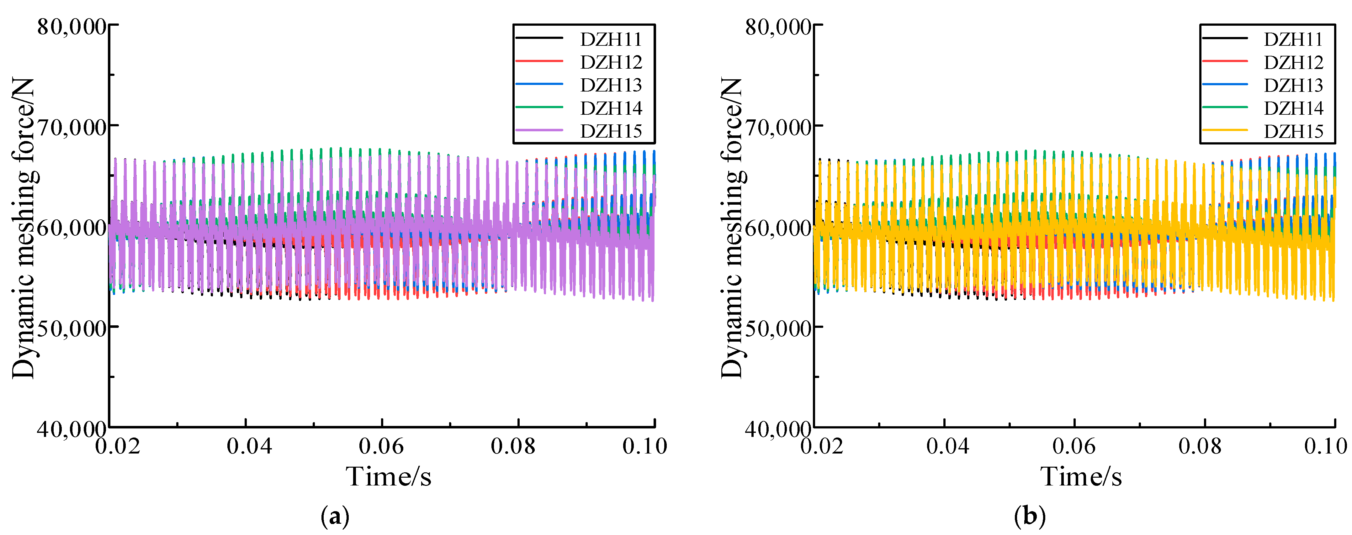
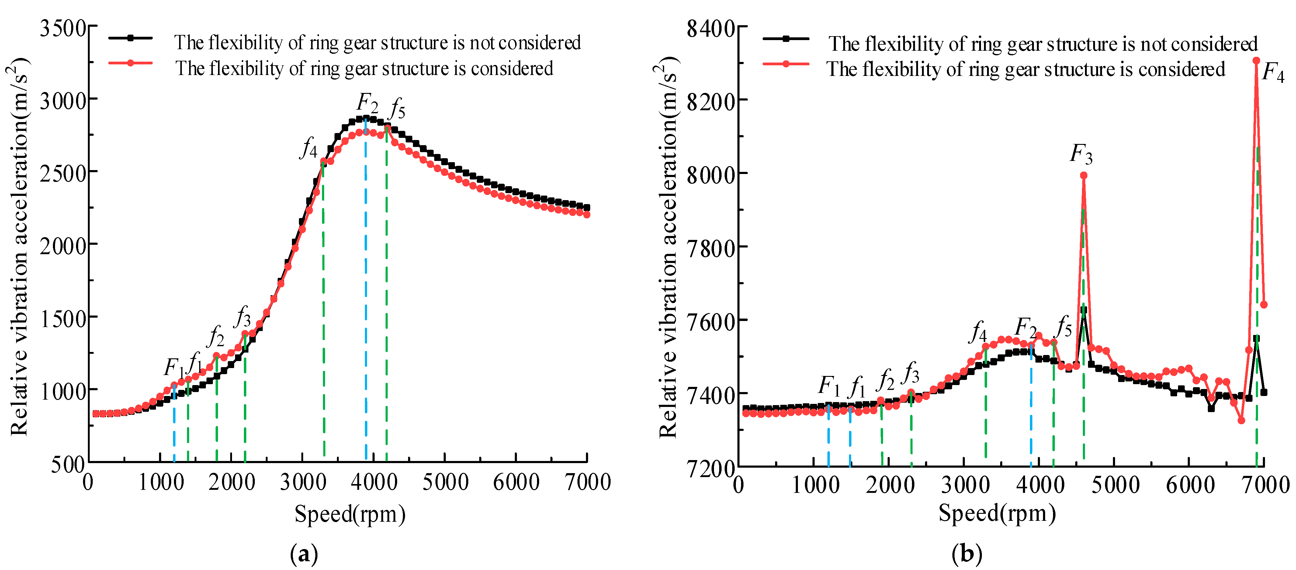
3.6. Influence of L-Shaped Flexible Ring Gear on Dynamic Response of Planetary Transmission System under All Working Conditions

In order to realize the dynamic performance of helicopter main reducer under actual working conditions, it is also necessary to predict the vibration of main reducer under different input speeds. Therefore, this section calculates the change trend of the root mean square value of the relative vibration acceleration along the meshing line of the internal and external meshing pairs of the planetary transmission system when the input speed of the sun wheel changes in [100 rpm, 7000 rpm] and before and after the flexible ring gear structure is included. As shown in Figure 12, the variation trend of the root mean square value of the relative vibration acceleration of the internal and external meshing pairs of the planetary transmission system with the input speed is shown.
As can be seen from Figure 12a, the root mean square value of the relative vibration acceleration increases with the increase of the input speed. When the input speed exceeds 3937.5 rpm, it decreases with the increase of the speed and gradually tends to be stable. When the structural vibration of the ring gear is not included, there are two obvious peaks (F1 and F2) in the variation trend curve of the relative vibration acceleration of the L-shaped flexible ring gear, and the external meshing pair of the system will cause strong vibration at the above two speeds. When the structural vibration of the ring gear is included, the relative vibration acceleration of the external meshing pair of the system decreases slightly as a whole, and five new small peaks (f1 to f5) appear, and the vibration at the original F1 increases slightly. According to the analysis, F1, f1, f2, and f3, respectively, correspond to the three nodal diameter, two nodal diameter, five nodal diameter and one nodal diameter traveling wave resonance frequency of L-shaped ring gear, while f4 and f5 correspond to the nodal circle up swing mode and coupling mode.
As can be seen from Figure 12b, since the ring gear is a fixed part, the growth range of the root mean square value of the relative vibration acceleration of the internal meshing gear pair is significantly weaker than that of the external meshing gear pair with the increase of the rotating speed. However, the overall mean value of relative vibration acceleration of internal meshing pair is stronger than that of external meshing pair. When the structural vibration of the ring gear is not included, there are four peaks (F1 to F4) in the internal meshing pair, and the vibration caused by F3 and F4 is the strongest. When the structural vibration of the internal ring gear is included, the relative vibration acceleration of the system decreases slightly in the low-speed range. In the high-speed range, the relative vibration acceleration of the system increases to a certain extent, and the fluctuation is more violent and chaotic, and several new peaks (f1 to f5) appear. After analysis, it can be seen that F1, f1, f2, and f3 correspond to the frequencies of three nodal diameter, two nodal diameter, five nodal diameter and one nodal diameter traveling wave resonance of L-shaped flexible ring gear, and f4 and f5 correspond to the nodal circle up swing mode and coupling mode of L-shaped flexible ring gear.

4. Conclusions

Based on SIMPACK software and its secondary development, this paper creates a system rigid-flexible coupling model that can accurately consider the dynamic excitation and structural vibration of planetary transmission system. The model solves the problems concerning that the flexibility and structural vibration of each component cannot be accurately introduced when the lumped mass method is used in the existing literature, as well as the huge amount of calculation and convergence difficulty of the finite element method. It also avoids the problems of the rigid-flexible coupling model in the existing literature, such as the inability to accurately define the time-varying meshing stiffness of the gear, the inability to really consider the actual meshing state of the gear, and the chaotic fluctuation of the meshing force caused by rigid contact. With the help of the coupling model, this paper further analyzes and obtains the structural vibration characteristics of L-shaped flexible ring gear and it influence on the system vibration.
(1)
When the nodal diameter traveling wave vibration is generated, the displacement response presents obvious periodic envelope vibration, which has the characteristics of beat vibration, the displacement response amplitude is significantly enhanced, and the unbalance loading effect of L-shaped flexible ring gear will be further increased.
(2)
When the nodal circle type resonance occurs, the displacement response on the rim does not show periodic envelope vibration. Compared with the nodal diameter traveling wave vibration, the resonance amplitude is smaller, resulting in the continuous change of the unbalance loading position on the tooth surface of L-shaped flexible ring gear. The coupling mode is a high order mode, which has the least influence on the structural vibration.
(3)
When the number of nodal diameters is equal to the number of planetary gears, the vibration displacement response of the structure is the largest. In addition, the vibration displacement response of traveling wave with low nodal diameter is stronger than that with high nodal diameter.
(4)
The low order mode and nodal diameter mode are not conducive to the load sharing performance of the system, and the nodal circle shaking mode will make the load sharing and dynamic load performance of the system worse.

Author Contributions

Conceptualization, S.H.; methodology, S.H. and Z.F.; software, S.H. and Y.G.; validation, C.L. and X.H.; formal analysis, S.H.; investigation, S.H.; resources, S.H.; data curation, S.H.; writing-original draft preparation, S.H.; writing-review and editing, S.H.; visualization, S.H.; supervision, Z.F.; project administration, S.H., C.L. and X.H.; funding acquisition, S.H., C.L. and X.H. All authors have read and agreed to the published version of the manuscript.

Funding

This research was funded by [the National Science Foundation of China] grant number [52105060] and [Natural Science Basic Research Program of Shanxi] grant number [2022JM271] and [Talent Introduction Fund of Anhui University of Science and technology] grant number [13220020].

Institutional Review Board Statement

Not applicable.

Informed Consent Statement

Not applicable.

Acknowledgments

The authors would like to thank the financial assistance and support from the National Science Foundation of China (no.52105060) and Natural Science Basic Research Program of Shaanxi (Program No.2022JM271) and Natural Science Special Project of Education Department of Shaanxi Province (No.21JK0790). We also thank anonymous reviewers and editors for their valuable comments and suggestions.

Conflicts of Interest

The authors declare that they have no conflicts of interest regarding the publication of this paper.

References

  1. Xu, H.C.; Qin, D.T. Vibration response of flexible spur ring gear with elastic foundation under internal excitation. J. Mech. Eng. 2008, 9, 161–167. [Google Scholar] [CrossRef]
  2. Qin, D.T. International gear transmission research status. J. Chongqing Univ. 2014, 8, 1–10. [Google Scholar]
  3. Hidaka, T.; Terauchi, Y.; Nagamura, K. Dynamic behavior of planetary gear: 7th report, influence of the thickness of the ring gear. Bull. JSME 1979, 22, 1142–1149. [Google Scholar] [CrossRef]
  4. Kahraman, A.; Ligata, H.; Singh, A. Influence of ring gear rim thickness on planetary gear set behavior. J. Mech. Des. 2012, 132, 021002. [Google Scholar] [CrossRef]
  5. Kahraman, A.; Vijayakar, S. Effect of internal gear flexibility on the quasi-static behavior of a planetary gear set. J. Mech. Des. 2001, 123, 408–415. [Google Scholar] [CrossRef]
  6. Kahraman, A.; Kharazi, A.A.; Umrani, M. A deformable body dynamic analysis of planetary gears with thin rims. J. Sound Vib. 2003, 262, 752–768. [Google Scholar] [CrossRef]
  7. Wang, L.X.; Wu, S.M.; Liu, J.H.; Chen, L.K. Dynamic characteristics analysis of the planetary gear system with the flexible ring. Mach. Des. Manuf. 2018, 1, 40–43. [Google Scholar]
  8. Bao, H.Y.; Zhou, X.J.; Zhu, R.P.; Lu, F.X. Load sharing analysis of planetary gear train with meshing beyond pitch point considering flexible deformable ring. J. Cent. South Univ. (Nat. Sci.) 2016, 47, 3005–3010. [Google Scholar]
  9. Li, L. Research on load-sharing design technology of flexible gear ring of planetary gear train. Xi’an Univ. Technol. 2019, 24, 286–289. [Google Scholar] [CrossRef]
  10. Hu, S.; Fang, Z.; Xu, Y.; Guan, Y.; Shen, R. Characteristics analysis of the new flexible ring gear for helicopter reducer. Proc. Inst. Mech. Eng. Part K J. Multi-Body Dyn. 2021, 235, 353–374. [Google Scholar] [CrossRef]
  11. Hu, S.Y.; Fang, Z.D.; Xu, Y.Q.; Shen, R. Analysis and comparison of the flexible and load sharing and dynamic characteristics load factor of the structure type of ring gear. J. Chongqing Univ. 2020, 12, 1–16. [Google Scholar]
  12. Ren, C.; Cui, B.Z.; Wang, B. Simulation research of Planetary wheel wear Fault based on ADAMS. Manuf. Technol. Mach. Tools 2019, 8, 113–116. [Google Scholar]
  13. Ma, C.Y.; Yi, J.D.; Xu, Y.G. Dynamic simulation analysis of planetary gearbox based on rigid-flexible coupling model. J. Beijing Univ. Technol. 2019, 45, 719–726. [Google Scholar] [CrossRef]
  14. Guo, H.Z.; Tang, C.J.; Chen, J.F. Dynamic simulation of planetary gear Train based on ADAMS. J. Mech. Transm. 2013, 5, 86–89. [Google Scholar]
  15. Lu, Y.; Ma, X.G.; Shu, Q.L. Planetary Gear Train dynamics Simulation based on RecurDyn. J. Shenyang Li Gong Univ. 2008, 27, 76–79. [Google Scholar]
  16. Ma, X.G.; Yang, W.; You, X.M. Multi-body dynamical analysis on rigid-flexible coupling for planetary gear system. Chin. J. Constr. Mach. 2009, 7, 24–30. [Google Scholar]
  17. Jia, X.P.; Fan, S.G.; Yu, K.L. Dynamical simulation of planetary coupling mechanism based on RecurDyn. J. Hunan Inst. Sci. Technol. (Nat. Sci. Ed.) 2014, 1, 43–46. [Google Scholar]
  18. Xu, H.B.; Xu, T.J.; Huang, Y.P. Analysis of Load Sharing of Planetary Gear Train Considering the Flexibility of Planet Carrier. J. Mech. Transm. 2016, 3, 107–111. [Google Scholar]
  19. Huang, X.C. Dynamics characteristic analysis of a multistage gear transmission mechanism based on SIMPACK. J. Mech. Transm. 2014, 38, 148–150. [Google Scholar]
  20. Chen, X.H.; Huang, Z.H.; Pu, J.L. Dynamics Simulation Analysis of Flexible Wheel set Based on ANSYS and SIMPACK. Electr. Drive Locomot. 2014, 1, 41–45. [Google Scholar]
  21. Miu, B.R.; Fang, X.H.; Fu, X.T. SIMPACK Dynamics Analysis Basics Tutorial; Southwest Jiao Tong University Press: Chengdu, China, 2008. [Google Scholar]
  22. Hu, S.Y.; Fang, Z.D.; Xu, Y.Q.; Guan, Y.B.; Shen, R. Meshing impact analysis of planetary transmission system considering the influence of multiple errors and its effect on the load sharing and dynamic load factor characteristics of the system. Proc. Inst. Mech. Eng. Part K J. Multi-Body Dyn. 2020, 235, 57–74. [Google Scholar] [CrossRef]
  23. Yan, L.T.; Zhu, Z.G.; Li, Q.H. Vibration of High-Speed Rotating Machinery; National Defense Industry Press: Beijing, China, 1994. [Google Scholar]
Figure 1. Three-dimensional diagram of L-shaped flexible ring gear and its planetary transmission system. (a) Main reducer, (b) planetary transmission system, (c) structural sketch, and (d) fixed form.
Machines 10 00339 g001
Figure 2. SIMPACK spring unit and move marker point setting diagram. (a) Setting between sun and planet wheel and (b) setting between ring gear and planet wheel.
Machines 10 00339 g002
Figure 3. Simulation model of planetary transmission system in SIMPACK. (a) Rigid coupling model and (b) rigid-flexible coupling model.
Machines 10 00339 g003
Figure 4. Dynamic meshing force with sun wheel error. (a) Lumped mass method and (b) rigid coupling model.
Machines 10 00339 g004
Figure 5. Dynamic meshing force with ring gear error. (a) Lumped mass method and (b) rigid coupling model.
Machines 10 00339 g005
Figure 6. Compares the relative displacements of internal meshing pair along the meshing line before and after the flexibility of L-shaped ring gear and structural vibration. (a) Lumped mass method and (b) rigid-flexible coupling model.
Machines 10 00339 g006
Figure 7. Vibration mode of ring gear.
Machines 10 00339 g007
Figure 8. Radial displacement response of rim of L-shaped flexible ring gear. (a) Radial displacement response and (b) spectrum of radial displacement response.
Machines 10 00339 g008
Figure 9. Radial displacement response of rim of L-shaped flexible ring gear. (a) Radial displacement response and (b) spectrum of radial displacement response.
Machines 10 00339 g009
Figure 10. Radial displacement response of rim of L-shaped flexible ring gear. (a) Radial displacement response and (b) spectrum of radial displacement response.
Machines 10 00339 g010
Figure 11. Comparison of maximum amplitude of radial vibration displacement response.
Machines 10 00339 g011
Figure 12. Trend of root mean square value of relative vibration acceleration with speed. (a) External meshing pair and (b) internal meshing pair.
Machines 10 00339 g012
Table 1. Basic parameters of the L-shaped flexible ring gear planetary transmission system.
ParametersUnitSunPlanetary GearL-Shaped Flexible Ring Gear
Tooth number Z1 and Z24855162
Normal module mnmm3.8
Normal pressure angle αndeg22.5
Face width Bmm88
Addendum hamm6.66.63.35
Dedendum hfmm2.052.054.825
Elastic modulus EGPa210
Density ρg/cm37.85
Speed vrpm1128
PowerkW2958.8
Table 2. The first 20 order natural frequencies of L-shaped flexible ring gear.
OrderFrequency/HzOrderFrequency/HzOrderFrequency/HzOrderFrequency/Hz
1645.376863.00111558.70162206.70
2645.6271081.60121559.00172207.40
3742.5881081.90132069.00182238.50
4744.3291388.10142128.10192430.20
5862.68101388.40152131.10202567.80
Table 3. The first 20 vibration modes of L-shaped flexible ring gear.
Machines 10 00339 i001 Machines 10 00339 i002 Machines 10 00339 i003 Machines 10 00339 i004 Machines 10 00339 i005
Three nodal diameterThree nodal diameterFour nodal diameterFour nodal diameterTwo nodal diameter
Machines 10 00339 i006 Machines 10 00339 i007 Machines 10 00339 i008 Machines 10 00339 i009 Machines 10 00339 i010
Two nodal diameterFive nodal diameterFive nodal diameterOne nodal diameterOne nodal diameter
Machines 10 00339 i011 Machines 10 00339 i012 Machines 10 00339 i013 Machines 10 00339 i014 Machines 10 00339 i015
Six nodal diameterSix nodal diameterNodal circle up swingSeven nodal diameterSeven nodal diameter
Machines 10 00339 i016 Machines 10 00339 i017 Machines 10 00339 i018 Machines 10 00339 i019 Machines 10 00339 i020
Coupling type 1Coupling type 1Nodal circle down swingNodal circle up swingCoupling type 2
Table 4. Traveling wave frequency and speed of L-shaped flexible ring gear.
TypeThree Nodal DiameterFour Nodal DiameterTwo Nodal DiameterFive Nodal DiameterOne Nodal DiameterSix Nodal DiameterSeven Nodal Diameter
Resonance speed (rpm)1045.731203.251397.861752.592249.242525.673448.31
Resonance frequency (Hz)645.37742.58862.681081.601388.101558.702128.10
Table 5. Comparison of vibration displacement response fluctuation amplitude.
TypeResonance Speed (rpm)3 Wheels/mm4 Wheels/mm5 Wheels/mm
One nodal diameter2249.241.88921.55381.1610
Two nodal diameter1397.861.80831.52001.1600
Three nodal diameter1045.734.51421.25370.8600
Four nodal diameter1203.250.86583.33120.2585
Five nodal diameter1752.591.32500.39192.5865
Nodal circle up swing3352.541.84421.76621.5120
Nodal circle down swing3627.191.6421.41811.3210
Coupling type 13575.670.82830.76880.6340
Coupling type 24160.782.36672.08441.7485
Publisher’s Note: MDPI stays neutral with regard to jurisdictional claims in published maps and institutional affiliations.

