Article

Development of an Anthropomorphic and Dexterous Dual-Arm System for Aerial Cooperative Bimanual Manipulation

1
Ji Hua Laboratory, Foshan 528200, China
2
Academy for Engineering & Technology-AI and Robot, Fudan University, Shanghai 200082, China
*
Author to whom correspondence should be addressed.
Machines 2022, 10(4), 273; https://doi.org/10.3390/machines10040273
Submission received: 18 February 2022 / Revised: 8 April 2022 / Accepted: 8 April 2022 / Published: 11 April 2022
(This article belongs to the Section Robotics, Mechatronics and Intelligent Machines)

Abstract

:
It is a challenging task for an aerial manipulator to complete dual-arm cooperative manipulation in an outdoor environment. In this study, a new dual-arm aerial manipulator system with flexible operation is developed. The dual-arm manipulator system is designed for the application of aerial manipulation, and it has the characteristics of low weight, low inertia, and a humanoid arm structure. The arm structure is composed of customized aluminum parts, each manipulator contains four degrees of freedom, similar to the arrangement of human joints, including shoulder yaw, shoulder pitch, elbow pitch, and wrist roll. Next, the workspace of the dual-arm manipulator is simulated and analyzed, and the relevant kinematic and dynamic models are deduced. Finally, through the lift load, accuracy and repeatability, cooperative bimanual manipulation tests on the test bench, and multiple groups of outdoor flight tests, the relevant performance analysis and verification of the dual-arm aerial manipulator system are carried out. The test results evaluate the feasibility of the designed dual-arm aerial manipulator system for outdoor cooperative manipulation.

1. Introduction

With the continuous maturity of navigation and control technology, unmanned aerial vehicles (UAVs) have been widely used in more and more fields, such as aerial photography [1], power line inspection [2], environmental modeling, and measurement [3], etc. However, most of these applications perceive the environment through the camera on the flight platform and can not actively operate the external environment, which limits the practical application range of aerial robots. In recent years, a new type of aerial robot with active operation ability, which is composed of a multi-degree-of-freedom manipulator and flight platform, has gradually become a research hotspot [4,5,6,7]. Compared with the traditional UAV, the operational aerial robot carrying the manipulator on the flight platform can obviously break through the limitations and deal with more operation scenarios, such as high-altitude sensor installation [8], aerial maintenance [9,10], goods sampling in areas inaccessible to humans [11], etc. Therefore, aerial manipulators have broad development prospects and have attracted the attention of a large number of researchers and commercial companies [12].
The aerial movement of the manipulator affects the real-time stability of the flight platform system, so the aerial operation is more challenging than the ground operation. For potential aerial operation applications, many research teams have designed a variety of aerial manipulator systems [13,14,15,16]. Due to the simple modeling of the system control and the easy arrangement of the single-arm structure at the center of mass of the system, the existing research mainly focuses on the single-arm aerial manipulator [17]. For example, Tognon et al. [18] designed a light aerial manipulator with two degrees of freedom for the detection of industrial equipment and carried out relevant tests for verification. Zhang et al. [19] studied the stability control of the aerial manipulator for grasping tasks in a strong wind interference environment, and relevant experimental results show that the controller can effectively make the aerial manipulator hover stably for control tasks. In order to realize the aerial cooperative operation of multiple aerial manipulators, Kim et al. [20] proposed a motion planner to ensure the safety of aerial maneuvering on the basis of analyzing the dynamic characteristics of the aerial manipulator and conducted relevant tests to verify it. The main challenge for aerial manipulators in grasping or contacting objects is how to solve the influence of manipulator motion and external force on the stability of aircraft. In the previous research, different control strategies are proposed and verified by corresponding aerial platform tests, including PI-D [21], adaptive controllers [22], multi-layer control architecture [23], and variable parameter integral backstepping [24], etc.
Compared with the single-arm aerial manipulator, the dual-arm aerial manipulator has the characteristics of a wide operation range and stable grasping, and more importantly, it can carry out the complicated aerial humanoid two-handed operation. Therefore, in recent years, more and more researchers have carried out research on the dual-arm aerial manipulator. For example, Suarez et al. [25,26,27,28,29,30] conducted continuous research work on dual-arm aerial manipulators, not only designing a lightweight and compliant dual-arm manipulator structure but also conducting tests and verifications applied to power lines and pipelines. For the application of valve rotation, Orsag et al. [31,32] proposed a dual-arm aerial manipulator system with multiple degrees of freedom and conducted the stability study and test verification of the manipulator under the contact force with the environment. Ramon-Soria et al. [33,34] designed a low-cost and lightweight 3D printed dual manipulator for aerial operation applications and conducted research and test verification of a vision-based autonomous grasping method. In addition, Ding et al. [35], Aguirre et al. [36], Caballero et al. [37], Yu et al. [38], and Lippiello et al. [39] also studied the relevant directions of the dual-arm aerial manipulator. Interestingly, some researchers have begun to study the multi-arm aerial manipulator. Recently, Paul et al. [40] developed a novel aerial operating system with three manipulators, which can not only grasp objects of various sizes but also use the manipulator as adaptive landing gear in uneven terrain.
From the existing research, there are few pieces of research on aerial manipulators with two arms or multiple arms, and most of them have been started in recent years. The existing research mainly focuses on the structural design of the aerial manipulator, system modeling, system stability control, and manipulator contact operation control algorithm. The relevant operational tests are usually just a simple aerial grab test or simulation verification. So far, there are few pieces of research on the application of dual-arm manipulators in complex assembly aerial operations, especially the aerial cooperative bimanual manipulation similar to humans.
This study mainly focuses on the development of a new dual-arm aerial manipulator with a dexterous operation function. The dual-arm manipulator is similar in size to human arms and can be integrated into a commercial multi-rotor platform. The dual-arm cooperative operation can be realized in an outdoor environment, as shown in Figure 1. The paper is structured as follows. The dual-arm aerial manipulator system is described in detail in Section 2. Subsequently, the kinematic model and dynamic model of the system are presented in Section 3. In Section 4, the related performance test and outdoor operation test of the dual-arm aerial manipulator are carried out. Finally, some conclusions are given in Section 5.

2. System Description

2.1. Dual-Arm Manipulator

The dual-arm manipulator better expands the operating range of the aerial robot to the target object. For example, a dual-arm manipulator can simultaneously grasp and manipulate two different objects, or handle large objects that cannot be manipulated by a single arm. When facing complex aerial operation requirements, the dual-arm aerial manipulator obviously has many advantages, because it can adapt to a variety of operation requirements, including the realization of the same complex cooperative operation as human hands. The design requirements of the manipulator system in this paper mainly consider two aspects: (1) The dual-arm manipulator has the characteristics of flexible movement and can realize the cooperative assembly operation just like human hands, and (2) The manipulator system can be integrated into the multi-rotor platform, and the dual-arm manipulator has the characteristics of low weight and low rotational inertia.

2.1.1. General Overview

Figure 2 shows the 3D model rendering of the designed dual-arm manipulator structure. The left and right arms of the structure are symmetrical, and each arm has four degrees of freedom. The joints from the top (shoulder) to the bottom (wrist) include shoulder yaw, shoulder pitch, elbow pitch, and wrist roll, which are similar to the arrangement of human joints. The overall structure adopts the bionic design principle, and the size proportion of the shoulder width of the two arms, the upper arm, and the forearm is similar to that of the human arm. This design draws on the structural advantages of the humanoid arm.
The ZED 2 stereo camera is mounted in the middle of the shoulders, which has a wide field of vision of 120°, low distortion, and good space target detection performance. The gripper is controlled by the actuator to open and close, which can grasp and operate the target object. Different operation requirements are taken into consideration in the structural design, so the clamping jaw adopts a modular design, which means that the corresponding end effector can be replaced for different operation scenarios.
In order to reduce the impact on the aerial platform caused by the movement of the dual manipulator, multiple actuators are placed as close as possible to the base of the aerial platform. In this way, the position of the center of mass of the manipulator is closer to the position of the center of mass of the aircraft, which is beneficial to reduce the inertia generated when the manipulator moves. The actuators used in the dual-arm structure are special intelligent servo systems for the robot. These servos integrate motor, gear, electronic equipment, and communication into a compact structure, which can provide high torque to weight ratio and real-time position information of the servo system. It also has temperature, voltage, and locked rotor protection. The servo control mode adopts the damping control mode, that is, the holding force of the steering gear can be set to realize the stability of the manipulator during operation. The model of the servo system and the main parameters related to each joint are shown in Table 1, in which the rotation angle range is measured according to the actual operating range of the designed manipulator structure.

2.1.2. Materials for the Frame Structure

When designing a dexterous aerial manipulator, another important concern is how to take into account the lightness of mass. As the densities of aluminum and carbon fiber are 2.8 g/cm3 and 1.8 g/cm3, respectively, they not only have low mass density and high strength performance, but also have lower manufacturing costs, so these two materials are mainly used in the design. The structure mainly uses aluminum parts for support and connection, and the dual manipulator structure contains a total of 41 aluminum parts. Except for the shoulder support plate, most of the parts have a thickness of 2 mm. In addition, a carbon fiber tube is used only in the forearm structure, with a diameter of 24 mm and a thickness of 2 mm.
As shown in Figure 2, excluding the binocular camera, the total mass of the dual-arm manipulator is 1.9 kg. The mass composition of the manipulator structure includes four parts, namely aluminum parts, actuators, carbon fiber, and other parts. Among them, aluminum parts account for 54.9%, and the main structures are made of aluminum materials; actuators account for 36.7%, and the two arms contain 10 actuators; carbon fiber accounts for 2.1%, and only two forearms use carbon fiber tubes in the entire structure, so the proportion is not high; other parts account for 6.3%, including actuator connecting wires, connecting screws, and other connecting parts, etc.

2.1.3. Workspace

The range of motion of the end effector directly determines the workspace of the aerial manipulator, and its size is an important index to measure the performance of the dual-arm robot. The workspace is the set of all the positions and postures that can be reached by the end effector. It is more complicated to solve the dual-arm manipulator with eight degrees of freedom through analytical formula, but it is relatively simple and fast to use the computer to solve it by numerical calculation. Therefore, in order to intuitively analyze the workspace of the dual-arm manipulator, this study establishes the robot model and uses the MATLAB simulation tool to analyze the workspace of the end effector.
The workspace of the manipulator designed in this study is determined by the shoulder joint and elbow joint, so the movable joints in the simulation model include the shoulder yaw joint, shoulder pitch joint, and elbow pitch joint. Figure 3a shows the simulation model established based on the dual-arm manipulator model and modified Denavit-Hartenberg (D–H) parameters. In the numerical calculation, the Monte Carlo method is used to solve the workspace, that is, N random quantities are generated by using the random function within the rotation angle range of each joint of the dual-arm manipulator, and the obtained random value of the joint angle is substituted into the forward kinematics equation, so as to obtain the position of the end effector [41]. The angle parameter setting in the simulation model takes into account the angle limit of the actual actuators. In addition, the landing gear is retracted during aerial operation, which takes into account that the landing gear will not affect the movement of the manipulator.
In Figure 3a, the red cylinder represents a movable joint, so both the left arm and the right arm have four corresponding red cylinders. For the red cylinder displayed at the coordinate [0,0,0] position, it is not a movable joint, but a benchmark for symmetrical modeling of the left arm and right arm. This is a fixed constraint during simulation analysis. In Figure 3b, in order to illustrate the workspace of a single manipulator on the YZ plane, the shoulder yaw joint is fixed and the other two joints can move. Figure 3c shows the projection of the dual-arm manipulator workspace on the XY plane, in which the left manipulator workspace and the right manipulator workspace are represented in blue and red respectively. Figure 3d shows the schematic diagram of the three-dimensional workspace of the dual-arm manipulator. The intersection area of blue and red in Figure 3c,d is the workspace that can be reached by two arm cooperative operation, and the union area represents the workspace that can be reached by single-arm operation.

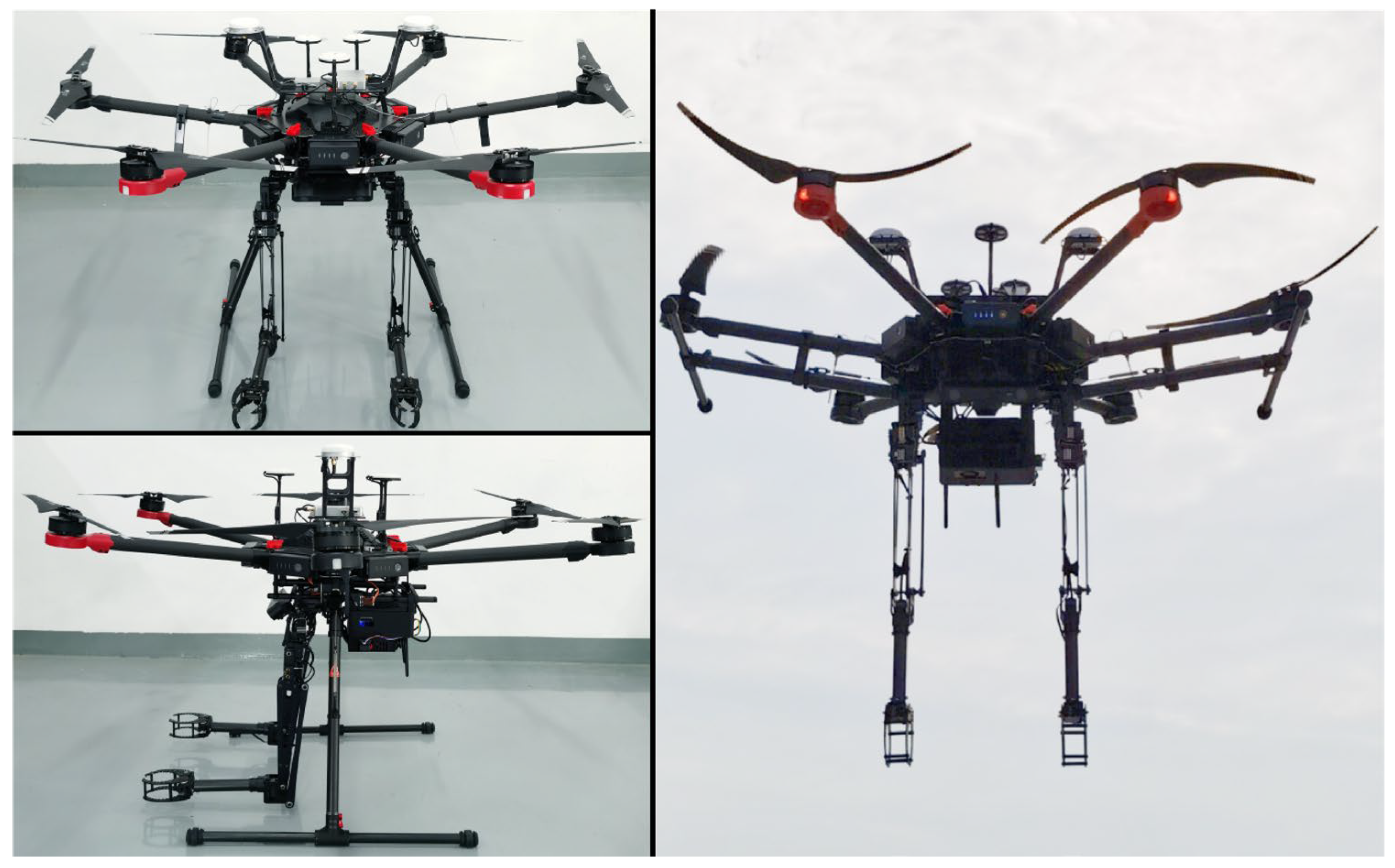
2.2. Aerial Manipulation System

2.2.1. Aerial Platform

The dual-arm manipulator designed in this study adopts a modular design and can be controlled and operated independently. The advantage is that it can be easily integrated into a commercial multi-rotor platform and can quickly and effectively carry out outdoor aerial operations. In general, the most relevant requirements when selecting a multi-rotor platform for aerial maneuvering applications are payload and time of flight, which determine the size and weight of the platform. At the same time, the influence of landing gear on the motion range and workspace of the manipulator during aerial operation should also be considered. As shown in Figure 4, the dexterous and lightweight dual-arm manipulator system developed in this study is integrated into DJI Matrice 600 Pro, in which the shoulder support plate structure is connected to the carbon fiber crossbar between the landing gear legs through lifting lugs.
The load of Matrice 600 Pro can reach 6 kg, and the hovering time is 16 min when the load is 6 kg. The system is equipped with a professional DJI A3 Pro flight control system and three sets of redundant Inertial Measurement Unit (IMU) and Global Navigation Satellite System (GNSS) modules. The A3 Pro adopts a fully optimized attitude resolution and multi-sensor fusion algorithm, and the system has good adaptability to ensure stable flight. The positioning accuracy and hovering stability of the flight platform are critical for the stable operation of the manipulator in the air, and the Matrice 600 Pro can be equipped with high-precision DJI Real-Time Kinematic (D-RTK) GNSS. D-RTK adopts dynamic difference technology, which can theoretically provide centimeter-level positioning accuracy. Traditional UAVs use barometers to determine the height, which is very susceptible to airflow fluctuations and is prone to serious height errors. D-RTK can provide more reliable height information, which will provide a platform stability guarantee for aerial manipulator operation.

2.2.2. Hardware/Software Architecture

The hardware/software structure of the developed dual-arm aerial manipulator system is shown in Figure 5. The aerial manipulator system is sent and controlled by the ground control station. A ZED 2 stereo camera is integrated into the system, which includes a magnetometer, barometer, and IMU to provide visual feedback and relevant image data to the ground control station and aerial processing system. The aerial manipulator system is equipped with a Jetson Xavier NX computer board, with Ubuntu 18.04 LTS, including 6-core NVIDIA Carmel ARM CPU, which is used for visual image and information processing in the air. The task manager can realize the remote operation, position control, visual servo, and other functions of the aerial manipulator system, and keep updating the status information of each servo actuator. The aerial flight system consists of a six-rotor platform and a DJI A3 Pro flight control system. The flight system can be controlled wirelessly by a remote controller.
The manipulator consists of two groups of servo systems, each arm is a group. Each arm includes three UART servos, as shown in Table 1, and two servos for the wrist and gripper. Each servo is identified by a unique ID so the control system can individually access each servo actuator to read its state and control its position. In the Figure, the PCA9685PW Servo Driver is a drive board for wrist and claw actuators. A WiFi/BT module is installed in the manipulator controller for data communication between the manipulator controller and the ground control station. The dual-arm aerial manipulator system is powered by a 22.2 V 6000 mAh Li-Po battery. Due to the different demand voltages of each module, the Li-Po battery provides 5 V, 8 V, and 12 V, respectively, through the step-down module.

2.2.3. Control

As shown in Figure 5, the controller of the dual-arm aerial manipulator system includes multi-rotor platform control and manipulator control, and the two parts are integrated through the Task Manager. Multi-rotor platform control uses a commercial DJI A3 Pro flight controller. Manipulator control includes the left arm controller and right arm controller.
The joint servo in the manipulator system is a position servo, and the control command of the joint adopts the angle value. Figure 6 shows the control structure of the dual-arm manipulator, the trajectory control of the manipulator is based on the inverse kinematics method. Through the desired trajectory position (PL, PR) in Cartesian space, a series of way-points (PkL, PkR) at the end of the manipulator are obtained. Through the obtained way-points, the inverse kinematics solution is used to obtain the angle control variables (qL, qR) required for the motion of each joint of the manipulator, and finally, make the motion trajectory of the end-effector meet the desired requirements.

3. Modeling

3.1. Kinematic Model

The aerial manipulator system contains three reference coordinate systems, namely ΣI, ΣB, and ΣE. Among them, ΣI is the earth fixed inertial coordinate system; ΣB is the multi-rotor body coordinate system, and the coordinate origin O coincides with the center of mass of the multi-rotor flight platform; ΣE is the coordinate system at the end of the manipulator, including the left arm ΣE1 and the right arm ΣE2.
p b = x , y , z T and v b = v x , v y , v z T are the absolute position and velocity of the multi-rotor flight platform in ΣI, respectively. The orientation of the six-rotor flight platform can be extracted from the ZYX Euler Angle, namely Φ b = ψ , θ , ϕ T . R B I represents the rotation matrix from ΣB to ΣI, and the specific form is:
R B I = c θ c ϕ s ψ s θ c ϕ c ψ s ϕ c ψ s θ c ϕ + s ψ s ϕ c θ s ϕ s ψ s θ s ϕ + c ψ c ϕ c ψ s θ s ϕ s ψ c ϕ s θ s ψ c θ c ψ c θ
where c and s are cosine function and sine function respectively.
The position and orientation of the end of the manipulator in ΣI are p e and R e respectively, which are related to the position and orientation of the multi-rotor flight platform as follows:
p e = p b + R B I p B b e R e = R B I R B b e
where p B b e and R B b e are the position and orientation of the end of the manipulator relative to the multi-rotor flight platform in ΣB, respectively.
The velocity and angular velocity of the end of the manipulator in ΣI are expressed as v e and ω e , respectively. By differentiating Equation (2), the relationship between v e and ω e and the velocity and angular velocity of the multi-rotor flight platform is as follows:
v e = v b + R B I ω b B × p B b e + v B b e ω e = R B I ω b B + ω B b e
where ω B b is the angular velocity of the multi-rotor flight platform in ΣB; v B b e and ω B b e are the velocity and angular velocity of the end of the manipulator in ΣB relative to the multi-rotor flight platform, respectively; v B b e and ω B b e have the following relationship with the joint angular velocity of the manipulator:
v B b e ω B b e = J B b e q q ˙
where q and q ˙ are the joint angle and joint angular velocity vectors of the manipulator, respectively. J B b e q is the Jacobian matrix of the manipulator and a function of the joint angle of the manipulator.

3.2. Dynamic Model

The dual-arm aerial manipulator system uses the Euler–Lagrangian method [25,42] to establish the dynamic model of the system:
d d t L ξ ˙ L ξ = Γ + Γ e x t
L ξ , ξ ˙ = K ξ , ξ ˙ V ξ
where L is the Lagrangian, defined as the difference between the kinetic energy K and the potential energy V of the system; Γ represents the generalized force generated by the system input; and Γext represents the generalized force corresponding to the external unmodeled disturbance; ξ is the vector of generalized coordinates.
This vector ξ includes the position of the multi-rotor and its orientation, along with the joint positions of two manipulators:
ξ = r U A V T , η U A V T , q 1 T , q 2 T T
where r UAV and η UAV are the position and orientation of the multi-rotor with respect to the inertial frame ΣI. q i = q 1 i , q 2 i , q 3 i , q 4 i T is the joint position vector for the i-th manipulator.
The aerial manipulator system can be regarded as a whole, in which the multi-rotor is connected to a fixed base through a 6-DOF joint, each manipulator is a subsystem, and the kinetic energy of the system is the sum of the kinetic energy of its various subsystems. System kinetic energy can be expressed as follows:
K = K U A V + K a r m s
where KUAV is the kinetic energy of the multi-rotor platform, and Karms is the kinetic energy of the dual-arm manipulator.
The potential energy due to gravity can be calculated with respect to the system center of mass as: V = g M T z c m . Here g is the acceleration due to gravity, M T is the total mass of the whole system, z c m is the altitude of the mass center of the whole system.
The equation of motion of the aerial manipulator system can be expressed in the following general form:
M ξ ξ ¨ + C ξ , ξ ˙ ξ ˙ + G ξ = Γ + Γ e x t
where M, C, G are, respectively, the inertia matrix, the centrifugal and Coriolis terms, and the gravitational force term.

4. Experimental Results

In order to evaluate the performance of the designed dual-arm aerial manipulator system, four tests are carried out with reference to the aerial manipulation benchmark [43]. Including lift load, accuracy and repeatability, cooperative bimanual manipulation, and outdoor flight tests.

4.1. Lift Load

The ability of lift load can reflect the operation ability of the manipulator on objects of different masses. This section evaluates the performance of the designed manipulator by carrying out lift load tests of different masses. The designed tests will be carried out on the test bench, as shown in Figure 7a. In the initial state, the entire mechanical arm is in a vertical state (as shown in Figure 7a), and the gripper clamps a rubber cylinder with a mass of 200 g. The whole lifting process is rotated by the elbow pitch joint actuator to lift the external load, while the other joint actuators are fixed. The whole lifting process lasts for 4 s, and the lifting angle of the forearm θ1 changes from 0° to 90° and it stops when the forearm reaches the horizontal position (as shown in Figure 7c). The manipulator controller generates the rotation angle of the elbow pitch joint actuator in a uniform process. Figure 7 shows the image sequence of the manipulator during the whole external load lifting process.
Figure 8 shows the power consumption of the elbow pitch joint actuator and the change of rotation angle θ2 during the external load lifting process. The real-time voltage and current of the actuator are obtained through the computer control interface, and then the power consumption is obtained. In this process, the actuator rotation angle θ2 varies from 0° to 110°. In Figure 9, the changes in the power consumption state of the elbow actuator under different loads and different measurement angles are analyzed. In this test, the swing angle of the elbow actuator is raised every 10° until the rotation angle reaches 110°, and the forearm is raised to the horizontal position. In this Figure, 0 g indicates that there is no external load on the gripper, and the entire lifting load corresponds to the weight of the arm itself.

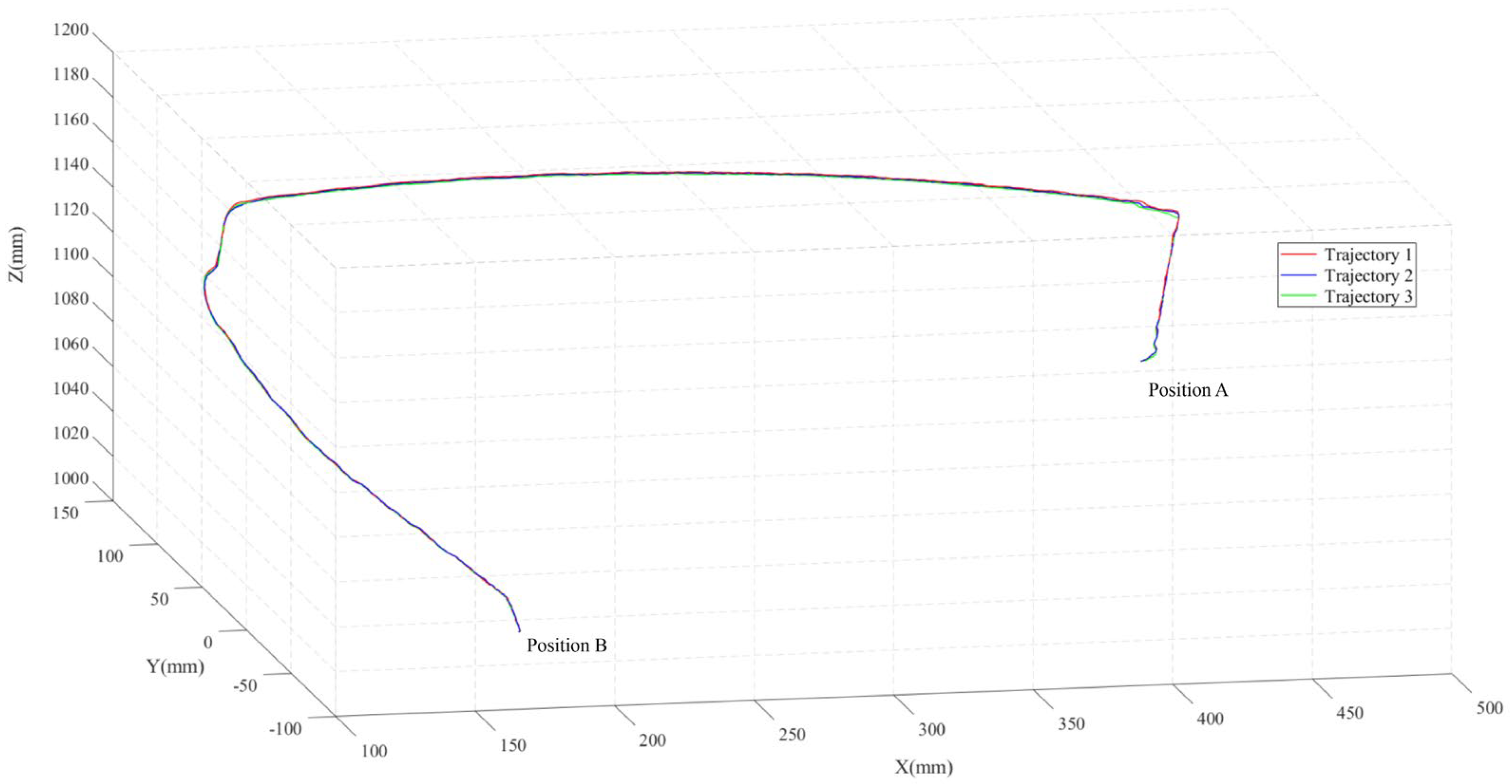
4.2. Accuracy and Repeatability

The motion trajectory accuracy and repeatability of the manipulator when operating the target object is an important aspect to reflect the operating performance. As shown in Figure 10, the relevant verification is carried out on the test bench by analyzing the motion trajectory of the manipulator during operation. The specific process is as follows: an object is placed at position A, and the right manipulator needs to grasp the object from position A and transfer it to position B. During the whole transfer operation, the gripper of the manipulator holds the object tightly. In the test, position A is 80 mm higher than position B in the vertical direction, and the mass of the captured object is 100 g. The whole test process is carried out in the environment where the motion capture system is arranged, and as shown in Figure 10, a reflective marker is fixed at the end of the right manipulator for motion trajectory capture. The motion capture system uses 12 infrared cameras for motion capture, the motion capture accuracy is 0.2 mm, and the sampling frequency of the system is 60 frames in 1 s. During the test, the same manipulator trajectory control program is repeated three times to record the motion trajectory of the end of the manipulator so as to analyze the accuracy and repeatability of each joint.
Figure 11 shows the trajectory data result of the marker of the right manipulator in the motion capture system. In order to evaluate the accuracy and repeatability, the manipulator carried out three complete operations, which are represented by lines of three different colors in the figure. It can be seen intuitively from Figure 11 that the motion trajectory of the manipulator has good repeatability during three complete operations.
The accuracy and repeatability of the manipulator trajectory are further quantitatively analyzed, and the amplitude deviation between trajectory 1 and trajectory 2 is calculated, as shown in Figure 12. Among them, the mean error is the root mean square error of the corresponding points of the trajectory 1 data and the trajectory 2 data, and the trajectory error is the deviation error between the corresponding points of the two trajectories at the same time. The mean error in Figure 12 is 0.56 mm, which shows that the designed aerial manipulator system has good control accuracy. The fluctuation range of the trajectory error is between 0 mm and 2.5 mm, which is mainly caused by the minimum control accuracy of the servo actuator itself and the structural hardware conditions, which is within the acceptable range. The less trajectory deviation at the end of the manipulator indicates that the designed manipulator has good operation accuracy and repeatability.

4.3. Cooperative Bimanual Manipulation

Compared with the single-arm aerial manipulator, the dual-arm aerial manipulator has the characteristics of a wide operation range. More importantly, the dual-arm aerial manipulator can carry out humanoid complex operations with both hands, such as the cooperative operation of two different workpieces, which will also be encountered in the aerial operation scene. At this time, it is obvious that the single-arm aerial manipulator cannot complete the task. In this test, the assembly operation of two different workpieces is carried out to verify that the designed manipulator system has the ability of cooperative bimanual manipulation. As shown in Figure 13, the test process is as follows: the left arm grabs the blue cylindrical boss, the right arm grabs the orange ring, gradually approaches the two workpieces, and finally inserts the ring into the boss. Among them, the outer diameter of the cylindrical boss is 38 mm, the inner diameter of the ring is 40 mm, and the weight of each of the two workpieces is 80 g. During the test, the reflective markers will be pasted on the two workpieces, respectively, as shown in the Figure, and the motion capture system will record the position changes of the two markers.
Figure 14 shows the position trajectory changes of two workpieces clamped by the left arm and the right arm on the XZ plane, respectively. It can be seen that in the whole operation process, the motion trajectory of the reflective markers of the left arm and the right arm is smooth, and finally can achieve better dual-arm cooperative operation accuracy. By analyzing the position trajectory of two operated workpieces, the cooperative operation ability of two arms can be reflected.

4.4. Outdoor Flight Tests

Considering the complex and multi-factor influence of the outdoor environment, it is challenging to carry out outdoor operations and application of the aerial manipulator system. This section will verify the feasibility of the designed aerial manipulator system for outdoor operation through two parts of aerial tests. In these tests, the wind scale of the outdoor environment is less than 1, and the flight control system uses the DJI A3 Pro autopilot.
The first part is the hovering manipulation stability test, including three groups of tests:
(1)
Test 1: The mechanical arm is vertically stationary, and each joint actuator does not move. Testing the height position change of the whole system when hovering at 2 m.
(2)
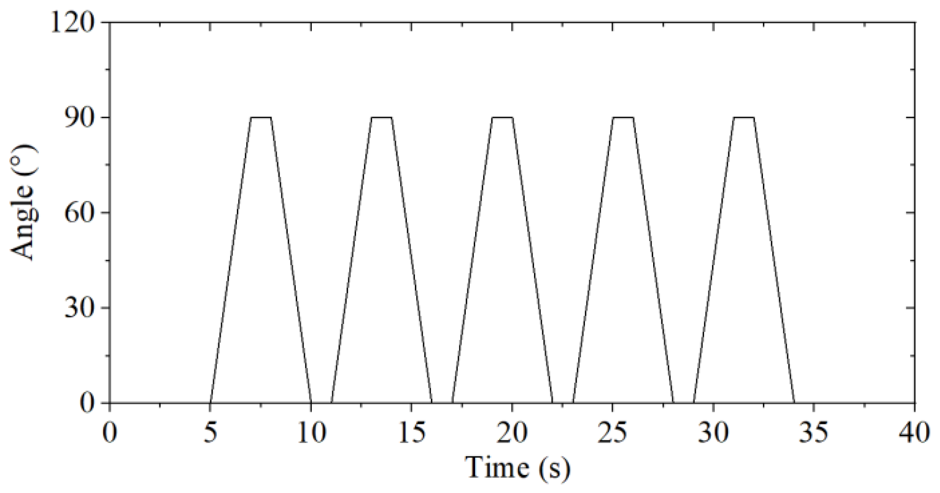
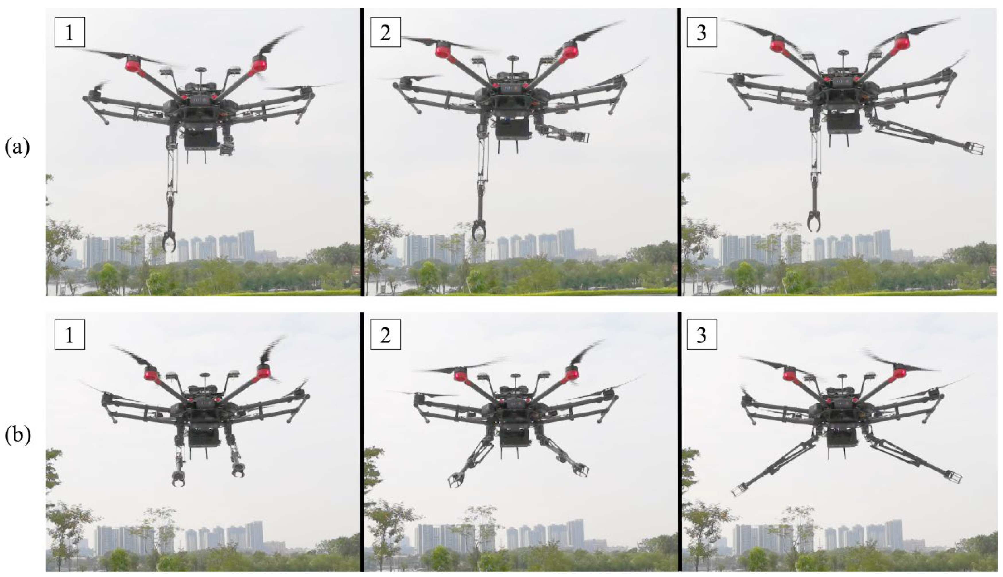
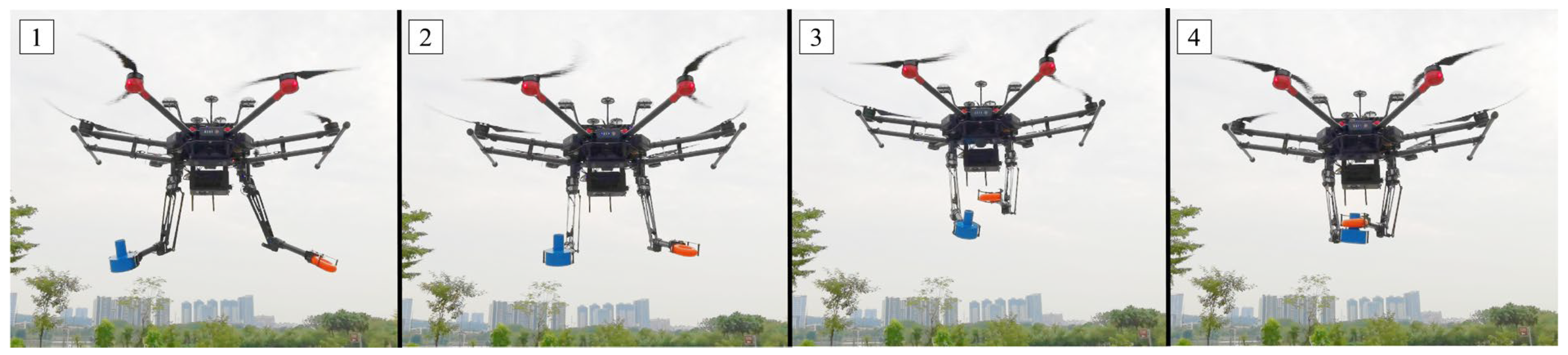
Test 2: The left mechanical arm does not move vertically, the shoulder yaw actuator angle of the right mechanical arm rotates, as shown in Figure 15, and other joint actuators do not move. Testing the influence of single-arm wide range motion on the stability of the system. The image sequence of the test process is shown in Figure 16a.
(3)
Test 3: The angles of the shoulder yaw actuators of the left and right manipulator arms rotate, as shown in Figure 15, at the same time, and the other joint actuators do not move. Testing the influence of two arms' motion on the stability of the system. The image sequence of the test process is shown in Figure 16b.
Figure 17 shows the height position change of the aerial manipulator system during hovering test 1, which is measured by an additional laser range sensor. The measurable distance of the sensor is 0.06–30 m, and the measurement accuracy is centimeter level. Compared with the predetermined height of 2 m, the maximum deviation of aerial platform height change is 19 cm. Outdoor hovering accuracy is affected by wind, navigation, flight control, and other factors, and the average hovering accuracy of the system in the test is within 10 cm.
Figure 18 and Figure 19 respectively show the acceleration changes in three directions of the aerial manipulator system in test 2 and test 3. It can be found that the maximum acceleration change in the X-axis and Y-axis directions is less than 0.2 m/s2, while the acceleration in the Z-axis direction fluctuates around 9.8 m/s2. There is no large acceleration mutation in the aerial manipulator system during the test. When the single-arm or dual-arm manipulator moves, the movement of the manipulator will inevitably cause some disturbance to the aerial platform. Considering that the force feedback of the manipulator is not provided to the attitude controller, the motion of the manipulator has no significant effect on the aerial platform. Therefore, the test results can quantitatively verify that the designed dual-arm aerial manipulator has the characteristics of low weight and low inertia.
The second part is the dual-arm cooperative manipulation test. The operation process in this test is similar to that in Section 4.3. The goal is to insert the ring grabbed by the right arm into the boss grabbed by the left arm. As shown in Figure 20, the aerial operation process of the dual-arm manipulator system is shown. In this process, two manipulators can operate two different workpieces smoothly and complete the cooperative operation task. The test results show that the aerial dual-arm manipulator system is feasible for outdoor cooperative bimanual manipulation.

5. Conclusions

In this study, we focused on the development of a new dual-arm aerial manipulator system with dexterous operation functions. The conclusions are summarized as follows:
(1)
A dual-arm manipulator system with low weight, low inertia, and a humanoid arm structure for aerial manipulation was developed. The weight of the dual-arm manipulator is 1.9 kg, and the arm frame structure supporting the servo actuator is composed of 41 customized aluminum parts. Each manipulator contains four degrees of freedom, similar to the arrangement of human joints, including shoulder yaw, shoulder pitch, elbow pitch, and wrist roll. The workspace of the dual-arm manipulator was simulated and analyzed, and the relevant kinematic and dynamic models were deduced.
(2)
Through various types of tests, the related performance of the dual-arm aerial manipulator system was analyzed and verified. Through the lift load, accuracy and repeatability, and cooperative bimanual manipulation tests on the test bench, the relevant operating performance of the designed dual-arm manipulator system was quantitatively evaluated. In the outdoor test, the manipulator was integrated on the commercial six-rotor platform, and the characteristics of low weight and low inertia of the designed dual-arm manipulator were verified through several groups of tests. At the same time, the test results showed the feasibility of the designed dual-arm aerial manipulator system for outdoor operation.
An application difficulty of aerial operation in an outdoor environment is how to control a dual-arm manipulator system with multiple actuators to perform cooperative operations. Therefore, in future work, a man–machine interactive remote manipulator control based on motion transmission will be considered. This will make it easy for the dual-arm aerial manipulator system to realize complex operation action control and can be better applied to a variety of scenarios with the requirements of aerial operation tasks.

Author Contributions

Conceptualization, P.Y. and H.W.; methodology, P.Y. and H.W.; software, H.W.; validation, P.Y. and H.W.; formal analysis, H.W.; investigation, Z.L.; data curation, H.W.; writing—original draft preparation, P.Y.; writing—review and editing, P.Y.; visualization, H.W.; supervision, Z.D. and L.Z.; project administration, P.Y.; funding acquisition, P.Y. All authors have read and agreed to the published version of the manuscript.

Funding

This research was funded by the Ji Hua Laboratory (X201301XB200; X190021TB194; X190021TB190).

Conflicts of Interest

The authors declare no conflict of interest.

References

  1. Reinoso, J.F.; Gonçalves, J.E.; Pereira, C.; Bleninger, T. Cartography for civil engineering projects: Photogrammetry supported by unmanned aerial vehicles. Iran. J. Sci. Technol. Trans. Civ. Eng. 2018, 42, 91–96. [Google Scholar] [CrossRef]
  2. Yang, L.; Fan, J.; Liu, Y.; Li, E.; Peng, J.; Liang, Z. A review on state-of-the-art power line inspection techniques. IEEE Trans. Instrum. Meas. 2020, 69, 9350–9365. [Google Scholar] [CrossRef]
  3. Annis, A.; Nardi, F.; Petroselli, A.; Apollonio, C.; Arcangeletti, E.; Tauro, F.; Belli, C.; Bianconi, R.; Grimaldi, S. UAV-DEMs for small-scale flood hazard mapping. Water 2020, 12, 1717. [Google Scholar] [CrossRef]
  4. Yu, Y.; Ding, X.; Zhu, J.J. Dynamic modeling and control for aerial arm-operating of a multi-propeller multifunction aerial robot. Adv. Robot. 2017, 31, 665–679. [Google Scholar] [CrossRef]
  5. Sun, Y.; Jing, Z.; Dong, P.; Huang, J.; Chen, W.; Leung, H. A Switchable Unmanned Aerial Manipulator System for Window-Cleaning Robot Installation. IEEE Robot. Autom. Lett. 2021, 6, 3483–3490. [Google Scholar] [CrossRef]
  6. Meng, X.; He, Y.; Han, J. Survey on aerial manipulator: System, modeling, and control. Robotica 2020, 38, 1288–1317. [Google Scholar] [CrossRef]
  7. Mimmo, N.; Macchelli, A.; Naldi, R.; Marconi, L. Robust motion control of aerial manipulators. Annu. Rev. Control 2020, 49, 230–238. [Google Scholar] [CrossRef]
  8. Hamaza, S.; Georgilas, I.; Fernandez, M.; Sanchez, P.; Richardson, T.; Heredia, G.; Ollero, A. Sensor installation and retrieval operations using an unmanned aerial manipulator. IEEE Robot. Autom. Lett. 2019, 4, 2793–2800. [Google Scholar] [CrossRef] [Green Version]
  9. Ollero, A.; Heredia, G.; Franchi, A.; Antonelli, A.; Kondak, K.; Sanfeliu, A.; Viguria, A.; Dios, J.R.M.; Pierri, F.; Cortes, J.; et al. The aeroarms project: Aerial robots with advanced manipulation capabilities for inspection and maintenance. IEEE Robot. Autom. Mag. 2018, 25, 12–23. [Google Scholar] [CrossRef] [Green Version]
  10. Chermprayong, P.; Zhang, K.; Xiao, F.; Kovac, M. An integrated delta manipulator for aerial repair: A new aerial robotic system. IEEE Robot. Autom. Mag. 2019, 26, 54–66. [Google Scholar] [CrossRef]
  11. Kutia, J.R.; Stol, K.A.; Xu, W. Aerial manipulator interactions with trees for canopy sampling. IEEE/ASME Trans. Mechatron. 2018, 23, 1740–1749. [Google Scholar] [CrossRef]
  12. Khamseh, H.B.; Janabi-Sharifi, F.; Abdessameud, A. Aerial manipulation—A literature survey. Robot. Auton. Syst. 2018, 107, 221–235. [Google Scholar] [CrossRef]
  13. Trujillo, M.Á.; Martínez-de Dios, J.R.; Martín, C.; Viguria, A.; Ollero, A. Novel aerial manipulator for accurate and robust industrial NDT contact inspection: A new tool for the oil and gas inspection industry. Sensors 2019, 19, 1305. [Google Scholar] [CrossRef] [PubMed] [Green Version]
  14. Hamaza, S.; Georgilas, I.; Heredia, G.; Ollero, A.; Richardson, T. Design, modeling, and control of an aerial manipulator for placement and retrieval of sensors in the environment. J. Field Robot. 2020, 37, 1224–1245. [Google Scholar] [CrossRef]
  15. Bartelds, T.; Capra, A.; Hamaza, S.; Fumagalli, M. Compliant aerial manipulators: Toward a new generation of aerial robotic workers. IEEE Robot. Autom. Lett. 2016, 1, 477–483. [Google Scholar] [CrossRef] [Green Version]
  16. Ruggiero, F.; Lippiello, V.; Ollero, A. Aerial manipulation: A literature review. IEEE Robot. Autom. Lett. 2018, 3, 1957–1964. [Google Scholar] [CrossRef] [Green Version]
  17. Mohiuddin, A.; Tarek, T.; Zweiri, Y.; Gan, D. A survey of single and multi-UAV aerial manipulation. Unmanned Syst. 2020, 8, 119–147. [Google Scholar] [CrossRef]
  18. Tognon, M.; Chávez, H.A.T.; Gasparin, E.; Sable, Q.; Bicego, D.; Mallet, A.; Lany, M.; Santi, G.; Revaz, B.; Cortes, J.; et al. A truly-redundant aerial manipulator system with application to push-and-slide inspection in industrial plants. IEEE Robot. Autom. Lett. 2019, 4, 1846–1851. [Google Scholar] [CrossRef] [Green Version]
  19. Zhang, G.; He, Y.; Dai, B.; Gu, F.; Yang, L.; Han, J.; Liu, G. Aerial grasping of an object in the strong wind: Robust control of an aerial manipulator. Appl. Sci. 2019, 9, 2230. [Google Scholar] [CrossRef] [Green Version]
  20. Kim, S.; Seo, H.; Shin, J.; Kim, H.J. Cooperative aerial manipulation using multirotors with multi-dof robotic arms. IEEE/ASME Trans. Mechatron. 2018, 23, 702–713. [Google Scholar] [CrossRef]
  21. Korpela, C.; Orsag, M.; Pekala, M.; Oh, P. Dynamic stability of a mobile manipulating unmanned aerial vehicle. In Proceedings of the 2013 IEEE International Conference on Robotics and Automation, Karlsruhe, Germany, 6–10 May 2013; pp. 4922–4927. [Google Scholar]
  22. Caccavale, F.; Giglio, G.; Muscio, G.; Pierri, F. Adaptive control for UAVs equipped with a robotic arm. IFAC Proc. Vol. 2014, 47, 11049–11054. [Google Scholar] [CrossRef] [Green Version]
  23. Ruggiero, F.; Trujillo, M.A.; Cano, R.; Ascorbe, H.; Viguria, A.; Peréz, C.; Lippiello, V.; Ollero, A.; Siciliano, B. A multilayer control for multirotor UAVs equipped with a servo robot arm. In Proceedings of the 2015 IEEE International Conference on Robotics and Automation (ICRA), Seattle, WA, USA, 26–30 May 2015; pp. 4014–4020. [Google Scholar]
  24. Jimenez-Cano, A.E.; Martin, J.; Heredia, G.; Ollero, A.; Cano, R. Control of an aerial robot with multi-link arm for assembly tasks. In Proceedings of the 2013 IEEE International Conference on Robotics and Automation, Karlsruhe, Germany, 6–10 May 2013; pp. 4916–4921. [Google Scholar]
  25. Suarez, A.; Jimenez-Cano, A.E.; Vega, V.M.; Heredia, G.; Rodriguez-Castaño, A.; Ollero, A. Design of a lightweight dual arm system for aerial manipulation. Mechatronics 2018, 50, 30–44. [Google Scholar] [CrossRef] [Green Version]
  26. Suarez, A.; Heredia, G.; Ollero, A. Physical-virtual impedance control in ultralightweight and compliant dual-arm aerial manipulators. IEEE Robot. Autom. Lett. 2018, 3, 2553–2560. [Google Scholar] [CrossRef] [Green Version]
  27. Suarez, A.; Grau, P.; Heredia, G.; Ollero, A. Winged aerial manipulation robot with dual arm and tail. Appl. Sci. 2020, 10, 4783. [Google Scholar] [CrossRef]
  28. Suarez, A.; Real, F.; Vega, V.M.; Heredia, G.; Rodriguez-Castano, A.; Ollero, A. Compliant bimanual aerial manipulation: Standard and long reach configurations. IEEE Access 2020, 8, 88844–88865. [Google Scholar] [CrossRef]
  29. Suarez, A.; Heredia, G.; Ollero, A. Design of an anthropomorphic, compliant, and lightweight dual arm for aerial manipulation. IEEE Access 2018, 6, 29173–29189. [Google Scholar] [CrossRef]
  30. Cacace, J.; Orozco-Soto, S.M.; Suarez, A.; Caballero, A.; Orsag, M.; Bogdan, S.; Vasiljevic, G.; Ebeid, E.; Rodriguez, J.; Ollero, A. Safe Local Aerial Manipulation for the Installation of Devices on Power Lines: AERIAL-CORE First Year Results and Designs. Appl. Sci. 2021, 11, 6220. [Google Scholar] [CrossRef]
  31. Korpela, C.; Orsag, M.; Oh, P. Towards valve turning using a dual-arm aerial manipulator. In Proceedings of the 2014 IEEE/RSJ International Conference on Intelligent Robots and Systems, Chicago, IL, USA, 14–18 September 2014; pp. 3411–3416. [Google Scholar]
  32. Orsag, M.; Korpela, C.; Bogdan, S.; Oh, P. Dexterous aerial robots—Mobile manipulation using unmanned aerial systems. IEEE Trans. Robot. 2017, 33, 1453–1466. [Google Scholar] [CrossRef]
  33. Ramon-Soria, P.; Arrue, B.C.; Ollero, A. Grasp planning and visual servoing for an outdoors aerial dual manipulator. Engineering 2020, 6, 77–88. [Google Scholar] [CrossRef]
  34. Perez-Jimenez, M.; Ramon-Soria, P.; Arrue, B.C.; Ollero, A. Hecatonquiros: Open-source hardware for aerial manipulation applications. Int. J. Adv. Robot. Syst. 2020, 17, 1729881420921622. [Google Scholar] [CrossRef]
  35. Yu, Y.; Ding, X. Safe landing analysis of a quadrotor aircraft with two legs. J. Intell. Robot. Syst. 2014, 76, 527–537. [Google Scholar] [CrossRef]
  36. Aguirre, O.A.; Nacato, J.C.; Andaluz, V.H. Virtual simulator for collaborative tasks of aerial manipulator robots. In Proceedings of the 2020 15th Iberian Conference on Information Systems and Technologies (CISTI), Seville, Spain, 15 July 2020; pp. 1–6. [Google Scholar]
  37. Caballero, A.; Béjar, M.; Rodriguez-Castaño, A.; Ollero, A. Motion planning for long reach manipulation in aerial robotic systems with two arms. In Proceedings of the 2017 European Conference on Mobile Robots (ECMR), Paris, France, 6–8 September 2017; pp. 1–7. [Google Scholar]
  38. Yu, P.; Wang, Z.; Wong, K.C. Exploring aerial perching and grasping with dual symmetric manipulators and compliant end-effectors. Int. J. Micro Air Veh. 2019, 11, 1756829319877416. [Google Scholar] [CrossRef] [Green Version]
  39. Lippiello, V.; Fontanelli, G.A.; Ruggiero, F. Image-based visual-impedance control of a dual-arm aerial manipulator. IEEE Robot. Autom. Lett. 2018, 3, 1856–1863. [Google Scholar] [CrossRef]
  40. Paul, H.; Miyazaki, R.; Ladig, R.; Shimonomura, K. TAMS: Development of a multipurpose three-arm aerial manipulator system. Adv. Robot. 2021, 35, 31–47. [Google Scholar] [CrossRef]
  41. Peidró, A.; Reinoso, Ó.; Gil, A.; Marín, J.M.; Payá, L. An improved Monte Carlo method based on Gaussian growth to calculate the workspace of robots. Eng. Appl. Artif. Intell. 2017, 64, 197–207. [Google Scholar] [CrossRef]
  42. Suarez, A.; Sanchez-Cuevas, P.J.; Heredia, G.; Ollero, A. Aerial Physical Interaction in Grabbing Conditions with Lightweight and Compliant Dual Arms. Appl. Sci. 2020, 10, 8927. [Google Scholar] [CrossRef]
  43. Suarez, A.; Vega, V.M.; Fernandez, M.; Heredia, G.; Ollero, A. Benchmarks for aerial manipulation. IEEE Robot. Autom. Lett. 2020, 5, 2650–2657. [Google Scholar] [CrossRef]
Figure 1. Dual-arm manipulator system for aerial cooperative bimanual manipulation.
Machines 10 00273 g001
Figure 2. Structure diagram of 8-DOF lightweight and dexterous dual-arm manipulator.
Machines 10 00273 g002
Figure 3. (a) Simulation model of workspace analysis; (b) Workspace projection on YZ plane; (c) Workspace projection on XY plane; (d) Schematic diagram of three-dimensional workspace.
Machines 10 00273 g003
Figure 4. Aerial manipulation system with different views.
Machines 10 00273 g004
Figure 5. The hardware/software architecture of the dual-arm aerial manipulator system.
Machines 10 00273 g005
Figure 6. Schematic diagram of arm control structure.
Machines 10 00273 g006
Figure 7. Lift load test of single manipulator when the external load is 200 g: (a) θ1 = 0°; (b) θ1 = 45°; (c) θ1 = 90°.
Machines 10 00273 g007
Figure 8. The change of power consumption and rotation angle of elbow actuator in the test of lifting 200 g external load.
Machines 10 00273 g008
Figure 9. Power consumption of elbow pitch actuator under different external loads.
Machines 10 00273 g009
Figure 10. Motion trajectory accuracy and repeatability test of manipulator.
Machines 10 00273 g010
Figure 11. Trajectory analysis of manipulator when moving object from position A to position B.
Machines 10 00273 g011
Figure 12. Deviation analysis of trajectory 1 and trajectory 2.
Machines 10 00273 g012
Figure 13. Test of cooperative bimanual manipulation.
Machines 10 00273 g013
Figure 14. Analysis of position trajectory changes in cooperative dual-arm manipulation test.
Machines 10 00273 g014
Figure 15. Change of rotation angle of shoulder yaw joint actuator.
Machines 10 00273 g015
Figure 16. Image sequence of hovering manipulation stability test in outdoor: (a) reciprocating swing of single-arm; (b) reciprocating swing of dual-arm.
Machines 10 00273 g016
Figure 17. Change of hovering height of dual-arm manipulator when it is stationary.
Machines 10 00273 g017
Figure 18. Acceleration variation of flight platform during single-arm reciprocating swing.
Machines 10 00273 g018
Figure 19. Acceleration variation of flight platform during dual-arm reciprocating swing.
Machines 10 00273 g019
Figure 20. Image sequence of dual-arm cooperative manipulation test outdoors.
Machines 10 00273 g020
Table 1. The main parameters of the arm joint.
JointServo ModelStall Torque (N·m)No-Load Speed (rad/s)Rotation Range (°)Actuator
Weight (g)
Shoulder yawRX8-U45H-M4.59.52[0,120]82
Shoulder pitchRX8-U45H-M4.59.52[0,100]82
Elbow pitchRX8-U45H-M4.59.52[0,110]82
Wrist rollPower HD-S151.514.5±9052
GripperPower HD-S151.514.5[0,90]52
Publisher’s Note: MDPI stays neutral with regard to jurisdictional claims in published maps and institutional affiliations.

