Article

Increasing Bending Performance of Soft Actuator by Silicon Rubbers of Multiple Hardness

1
School of Mechanical Engineering and Automation, Beihang University, Beijing 100191, China
2
Beihang Hangzhou Innovation Institute Yuhang, Hangzhou 311121, China
3
Key Laboratory of Intelligent Manufacturing Technology for Aeronautics Advanced Equipment, Ministry of Industry and Information Technology, Beihang University, Beijing 100191, China
*
Author to whom correspondence should be addressed.
Machines 2022, 10(4), 272; https://doi.org/10.3390/machines10040272
Submission received: 16 February 2022 / Revised: 20 March 2022 / Accepted: 7 April 2022 / Published: 11 April 2022
(This article belongs to the Topic Recent Advances in Robotics and Networks)

Abstract

:
In this study, a method for fabricating actuators made of various silicone materials is proposed to improve the flexural performance of soft-body actuators. Specifically, the redundant deformation part of the soft actuator was replaced with a material with higher hardness to limit the redundant deformation of the soft actuator. Materials with lower hardness were used to produce the main deformation part of the soft actuator, so that the soft body actuator could perform greater bending under the same air pressure and create a greater bending force. In addition, the fabricated actuator was divided into three regions in this study: the periphery of the chamber, the chamber wall (the main curved part), and the bottom surface of the actuator. The impact on the overall performance of soft-body actuators when using silicone materials with different hardness in these three regions was explored in this study. According to the idea of the multi-hardness silicone structure, an actuator with seven chambers was fabricated, and the performance of the actuator was improved by 90.72% compared with the uniform material actuator.

Graphical Abstract

1. Introduction

As soft robotic technology develops, soft robots are being applied to different fields such as medical, sorting and transporting, and bio-inspired products owing to their outstanding advantages such as strong adaptability, gentle man-machine interaction, simple control, fast iteration of design, and biomimetic nature [1]. Nevertheless, current soft robots made of flexible materials (polymers [1], elastomers [1], hydrogels [2], and particles [3]) still have some problems. Actually, many actuating pneumatic soft robots that adapt to air as a power supply have difficulty sustaining a stable working state under high load or high acceleration owing to the compressibility of air. Moreover, the energy efficiency of pneumatic soft robots is rather low because most energy is lost during redundant deformation and inflation/deflation. In addition, the response speed of soft robots is lower than that of traditional rigid robots, and hysteresis occurs during the actuation. Therefore, increasing the response speed, bending performance, and tip capacity generated by bending has been the focus of researchers in the field of soft robots.
Soft robots can be operated with several different drive modes including pneumatics, shape-memory alloys and electrically powered methods, and their motions are divided into fast (>1 Hz) and slow (<0.1 Hz) responses [1]. Using a shape memory alloy (SMA), a single fast actuation (<100 ms) can be achieved [4], in which deformation occurs within 100 ms, and a linear velocity of over 0.2 m/s is generated. The electrically powered methods can offer several advantages, including high-speed actuation, high strain, silent operation, and self-sensing, but they need to have a rigid frame and pre-stretch to successfully finish the actuating task. The electro-hydraulic method is a newly developed electrically powered actuating method. Kellaris and Mao proposed different electrohydrodynamic actuators to solve the aforementioned problems and already showed the potential application in the medical, industrial, and robotic areas [5,6]. The pneumatic actuation method is more favored than the others because of its advantages, such as simple mode and strong pressure resistance. High-speed actuation with gas is achieved using the explosion of a mixture of methane and oxygen in a gas-filled mesh to generate rapid (millisecond) pressure pulses [7]. While this explosion can produce rapid motion, precise control of the robot’s motion is currently not possible and combustion is not a suitable power source for applications in medicine. Therefore, traditional and safe pneumatic networks capable of fast startup (>1 Hz) over the entire range of motion are required for soft robots.
With the purpose of increasing the bending performance of soft actuators, Marchese et al. [8] studied the types and actual manufacturing methods of current soft actuators and elaborated the main factors that affect the bending or deformations of various soft actuators, establishing frameworks and basics of subsequent research on soft actuators. Based on research on the energy efficiency of soft robots, Shui et al. [9] analyzed the reasons for the low energy efficiency of soft robots and proposed plausible methods for improving the energy efficiency of soft robots in the future. Related studies have adopted unique designs or fabrication methods to increase the bending performance of soft actuators. For example, metals or polymers with low melting points are used in soft actuators to achieve variable stiffness of soft actuators [10,11,12]. Some researchers have used shape memory alloys and polymers as a means of actuation [13,14]. Other researchers have used particle or layer jamming to improve the loading capacity of soft actuators. The use of multiple materials to fabricate actuators is a research topic. Zhang et al., Byrne et al., and du Pasquier et al. [15,16,17] fabricated soft actuators through multi-material 3D printing and achieved improvements in the performance of soft actuators.
So far, there are many methods that help improve the performance of soft actuators. Many researchers believed that stiffness modulation is a promising solution to improve the performance (exerting sufficient force and maintaining position stably) of pneumatic soft robots [18]. Brown et al. [3] designed a universal robotic gripper based on the jamming of granular materials to improve the stiffness of the gripper. Similarly, Chen et al. [18] utilized the so-called jamming approaches to achieve stiffness modulation, and the stiffness can be improved by the interaction between different adjacent particles. Mao et al. [19] investigate the contraction waves of Belousov–Zhabotinsky gel, which could be a potential material used for soft actuators. However, studies on changing the local ballet structures of pneumatic soft actuators and restricting redundant deformations of these local structures to increase bending performance are rare. Mosadegh et al. [20] developed ballonet structures for pneumatic soft actuators by varying the thickness of the actuator ballonets. This design enabled the actuator to respond quickly to air pressure and yield greater tip forces. In addition, some studies [21,22,23] changed the bottom materials of soft actuators or introduced non-stretchable layers to increase the bending curves or tip forces of the actuators. Albadi et al. [24] designed a gripper with variable stiffness that was capable of grasping a wide range of objects without complex control schemes. The gripper could deform to conform to the object being grasped, indicating that the gripper was easy to control with simple grasping steps. In addition, the soft nature of the gripper makes it more suitable for handling fragile and delicate objects than traditional rigid grippers. Fei et al. [25] proposed the addition of a bending device to a gripper to improve its adaptability. With a double-sided air chamber, the gripping stiffness and strength of the gripper jaw can be adjusted by changing the pressure and pressure difference between the two air chambers, and the deflection stiffness and strength can be adjusted by the wrist in the same way.
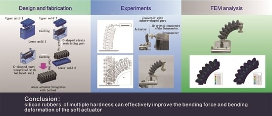
Actually, different parts of a soft actuator may have different functions and be caused different deformation. Based on this consideration, focusing on the local structures of soft actuators and restricting unexpected deformations, that is, reducing the stretching of non-actuating parts, can also effectively increase the bending performance of soft actuators. Inspired by this idea, this study proposes a unique design and fabrication method for pneumatic soft actuators. The actuator is divided into three parts, and various silicon rubbers with different hardness values are used to fabricate these parts according to practical requirements. The C-shaped peripheral parts and actuator ballonets that easily undergo redundant deformation and the bottom part of the actuator can be fabricated using relatively harder silicon rubbers. As such, the bending performance and tip forces generated by pneumatic soft actuators can be increased to a certain degree. The results of both computer simulations and physical printing experiments conducted by us will also be reported to demonstrate the effectiveness of the proposed methodology.

2. Structural Design and Finite Element Analysis

2.1. Structural Design

By analyzing the deformation of the pneumatic soft-body actuator under load, a new type of multi-material soft-body actuator was proposed in this study to reduce the local deformation of the actuator and improve its bending performance. Generally, a pneumatic soft-body actuator can be viewed as an array of several simple air chambers. According to the deformation characteristics of the air chamber when the actuator is actuated, the air chamber can be divided into three main units: the ballonet wall, C-shaped strain-restricting part, and bottom (Figure 1). The ballonet wall is the main driving unit of the soft actuator and bending of the actuator is realized by the expansion and deformation of the ballonet wall. It can be observed that the actual deformation degree of the C-shaped strain-restricting part was limited, and the degree of softness and hardness of the bottom is related to the tip force output by the soft body actuator. To this end, this study aims to investigate the influence of the ballonet wall, C-shaped strain-restricting part, and bottom made of silicone with different hardness on the performance of the pneumatic soft body actuator.
According to the driving principle of ordinary pneumatic actuators, the bending of the actuator is caused by uneven deformation between the ballonet wall and bottom. The ballonet wall deformed more than the bottom, causing the entire actuator to flex. The deformation of the air chamber is mainly due to the bending deformation of the ballonet wall, including expansion and stretching. Therefore, to ensure a larger deformation of the air chamber and achieve better bending performance, the ballonet wall can be made of softer silicone rubber, which can produce a larger deformation under the same pneumatic pressure. Although the C-type strain-restricting part does not actually affect the overall bending performance of the soft-body actuator, the local expansion of the C-shape strain- restricting part, caused by excessive input of aerodynamic load or too small material hardness of the part, hinders the bending deformation of the soft body actuator and reduces the energy use efficiency.
The dimensional information of the actuator can be found in Figure 1. Actually, the whole length and width of the actuator can be changed according to the working requirement, so we only paid attention to the design of one single chamber. From the zoom in area, we define three key parameters of the actuator, i.e., the space between adjacent digits (denoted as a), the wall thickness of one chamber (denoted as b), and the thickness of the chamber bottom (denoted as c). The space between adjacent digits should be as small as possible in order to transfer the inflation to a bending moment. The wall thickness b is uniform and should be determined carefully. If b is too large, the deformation of the actuator is limited, and if b is too small, the strength of the entire actuator is weak especially for the situation with large deformation. It should be mentioned that the bottom of the actuator is not a simple cuboid (see the cross-section of the actuator in Figure 1), so the thickness c that we defined can be considered as an effective thickness. The other part of the actuator bottom is used to fit the shape of objects.

2.2. FEM Analysis

In this study, the ABAQUS numerical simulation software was used to simulate the bending performance of a soft actuator composed of a ballonet wall, a C-shaped strain-restricting part, and a bottom made of silicone with different hardness to study the influence of different hardness silicone materials on the performance of the soft-body actuator. First, a soft actuator model is established, as shown in Figure 1. The soft actuator consists of 7 air chambers. The ballonet wall, C-shaped strain-restricting part, and bottom of each chamber are shown in Figure 1 in different colors. The Abaqus 6.11 computer-aided engineering (CAE) software package (Simulia, Dassault Systems) was used in this study to solve the soft-body actuator simulation process using standard/implicit finite element methods. Based on the model of the soft body actuator shown in Figure 1, the model was divided into tetrahedral meshes via hypermesh, and a simulation model was established, as shown in Figure 2.
To ensure accuracy, the simulation model had 900,070 tetrahedral mesh elements and 199,540 mesh nodes. Based on the actual application, we selected silicone rubber as the material of the software actuator and defined six silicone rubber materials according to the difference in hardness of different silicone rubbers, whose elastic modulus and Poisson’s ratio are shown in Table 1. To simulate the actual working conditions of the soft-body actuator, this study defines the boundary conditions of the simulation model: (1) considering the influence of gravity on the actuator; (2) under no-load conditions, both the inside and outside of the air chamber of the soft-body actuator are affected by 1 atmosphere; and (3) as the outer surfaces of adjacent air chambers are squeezed against each other in the inflation and expansion process of the actuator, the interaction between the surfaces of adjacent air chambers is set (as shown in Figure 2).
Because the simulation analysis mainly discussed the influence of the hardness of the silicone material in different parts of the soft actuator on the bending performance, one end of the simulation model was set as the loading end (as shown in Figure 2), and a gas with a pressure of 30, 40, 50, and 60 Kpa were used as the input of the simulation, respectively. By analyzing the bending angle of the loaded soft-body actuator (the bending angle is defined as the angle between the planes where the head and tail ends of the soft actuator are in the loaded state, as shown in Figure 3), the effect of hardness changes in the C-shaped strain-restricting parts (Simulation 1), ballonet wall (Simulation 2), and bottom (Simulation 3) on the bending performance of the soft actuator was investigated in this study. The material properties of each component are listed in Table 2.
The results of the three experiments are shown in Figure 4. Generally, for simulations 1–3, it can be clearly seen that as the increase of the air pressure, the bending angle becomes larger and larger intuitively. However, in Simulation 1, by changing the hardness of the silicon material in the C-shape strain-restricting part, we found that the bending angle of the soft actuator decreased continuously with an increase in the hardness of the silicon material. However, from the bending results and stress distribution of the soft actuator shown in Figure 5 (the hardness of the C-shaped strain-restricting part is Si-58), it can be seen that the C-shaped strain-restricting part bears greater stress. Therefore, when using a C-shaped strain-limiting part with high hardness, the deformation of the air chamber can be limited, and the ballonet wall can be fully expanded to avoid the large deformation of the C-shaped strain-restricting part (see the situation mentioned in Section 4 for details). However, the degree of expansion of the ballonet wall is directly related to the bending performance of the soft-body actuator. From the results of Simulation 2, it can be seen that when the hardness of the ballonet wall is Si-10, the overall actuation effect of the soft body actuator is the best. Hence, the ballonet wall should be made of softer silicone material. In addition, it can be observed from the simulation results that the hardness of the base has a limited effect on the bending angle of the soft-body actuator. Although it is slightly decreased, the effect is not obvious compared with the C-shaped strain-restricting part and ballonet wall. As such, from the simulation results, the authors think that obviously, the softest material should be used to make the ballonet wall, and meanwhile, considering that C-shaped strain-restricting part can limit the redundant deformation of the actuator, the authors plan to use a silicone rubber with greater hardness (e.g., Si-58). Moreover, for the bottom of the actuator, we believe that the tip force is related to hardness of bottom, which will be verified in the following experimental section.

3. Fabrication

The soft actuator was fabricated via mold casting, and the fabrication process is shown in Figure 6. In order to successfully fabricate the soft actuator, the authors carefully designed the fabrication molds, which consist of two lower molds and two upper molds (Figure 6). The corresponding molds were 3D printed using a stereolithography 3D printer (Form 2, Formlabs cooperation). First, the upper mold for producing the C-shaped strain-restricting part, the corresponding lower mold, and harder silicon rubber are used to form a C-shaped strain-restricting part. Then, the upper mold is withdrawn, but the C-shaped strain-restricting part is left in the lower mold. Subsequently, based on the above production, the upper mold for producing the ballonet wall and softer silicon rubber is used to form the ballonet wall, so that the upper part of the actuator is completed. The upper part of the actuator (which included a C-shaped strain-restricting part and ballonet wall) was removed from the lower mold, and another lower mold was applied to form the bottom of the actuator. The entire actuator was completed after fabricating the bottom. The dimensions of the actuator (length × width × height) are 47 mm × 18 mm × 18.75 mm.
It is noteworthy that the outermost ballonet walls on both sides are still made of harder silicon rubber so that the connecting parts are unable to slide out from the connectors at both ends, ensuring airtightness and normal actuation.
As for fabricating materials, because the effects of silicon rubbers with different hardness have been simulated, in order to verify the simulation result, in this paper, we will fabricate different actuators and do the comparisons. When fabricating the actuator, a principle is followed, according to which the hardness of the C-shaped strain-restricting part should be greater than that of the ballonet wall, because this principle ensures the aforementioned restriction of redundant deformation. The Shore A harnesseses of the adopted silicon rubbers are 10, 20, 30, 40, 50, and 58 (i.e., the Si-10, Si-20, Si-30, Si-40, Si-50, and Si-58 mentioned in Section 2). The exact materials that satisfy all hardnesses are listed in Table 3. In order to describe the actuator when it is fabricated by multiple silicon rubbers, a definition of description format of actuator based on the hardness composition of the actuator is employed: “hardness of C-shaped strain-restricting part-hardness of ballonet wall-hardness of bottom”. For example, “58-30-58” describes an actuator fabricated using different silicon rubbers. The adopted silicon rubbers were obtained from Elkem Cooperation and Smooth-On Cooperation, and the details are listed in Table 1.

4. Experiments

Actuators with different hardness compositions were fabricated to explore the effects of the hardness of each actuator component. For the experimental groups, the hardness of one component was the only variable in each group, and the hardness of the other two components was fixed based on the test experience. When exploring the effects of the hardness of the C-shaped strain-restricting part, the hardness of the C-shaped strain-restricting part was set to 30, 40, 50, and 58, while the hardness of the ballonet wall was fixed at 30, while the hardness of the bottom was 58. As for the effects of the ballonet, the hardness of both the C-shaped strain-restricting part and the bottom are fixed at 58, and the hardness of the ballonet wall changes within 10, 20, 30, 40, and 50. For the effects of the bottom, the hardness of the bottom was set to 10, 20, 30, 40, 50, and 58, while the hardness of the ballonet wall was fixed at 30, and the hardness of the C-shaped strain-restricting part was 58. The above discussion and testing range are the same as the simulation.

4.1. Tip Force Tests

The experimental settings for the tip force measurement test are shown in Figure 7. A test platform was established, in which the air pump (not shown in Figure 7) supplied compressed air, the proportional valve (ITV1030-311N, SMC Corporation, Tokyo, Japan) adjusted the pneumatic pressure of the gas circuit, and a barometer (DP102, Panasonic Corporation, Osaka, Japan) was applied to monitor the real-time pressure value. The position of the actuator was fixed using a supporting bracket connected to a holding bench. As shown in Figure 7b, the actuator was placed vertically when measuring the tip force such that the direction of the tip force would be horizontal. Thus, a horizontally placed dynamometer (SF-500, Wenzhou Yiding Instrument Manufacturing Co., Ltd., Wenzhou, China), along with 3D printed connectors, was used to measure the tip force of the actuator.
It should be noted that, in order to measure the tip force, two different connectors for both ends of the actuator were designed. A connector at the bottom end ensures that the actuator is fixed, and the other connector with a sphere-shaped part ensures that it makes sufficient contact with the dynamometer when the actuator bends. The connector of the dynamometer was also redesigned and 3D printed, and its relatively larger contact area ensured its contact with the sphere-shaped connector of the actuator during testing. The surface of the dynamometer connector was covered with silicone oil to reduce the influence of friction. The tip forces in the aforementioned experimental groups were measured. Five measurements were performed for each actuator, and the average was recorded as the tip-force value. For every experimental group, the tip forces under pressure of 30, 40, 50, and 60 kPa were also measured. This pressure setting was decided for the reason that some harder actuators are difficult to actuate when the pressure is too low, while local expansion or inflation rupture happens at high pressure.
The experimental results of tip force are shown in Figure 8. The data suggest that if the C-shaped strain-restricting part has reached a certain hardness, the tip forces will increase owing to the restriction of the redundant deformation. However, the soft C-shaped strain-restricting part hinders the generation of the tip force. As for the phenomenon that the actuator “30-30-58” generates larger tip force than “40-30-58”, it can possibly be attributed to slight local expansion of C-shaped strain-restricting part of “30-30-58” actuator that increases the bending angle, thus increasing tip force slightly. For the ballonet wall, which is the main actuating part, the data show the tendency of the tip force to increase with a decrease in the hardness of the ballonet wall. In addition, an increase in pneumatic pressure helps increase the tip force to a relatively large extent if the ballonet wall is softer. Regarding the bottom of the actuator, which is the transmission medium of the tip force, the experimental data suggest that an actuator with a harder bottom generates a larger tip force. When the bottom is soft, the outputting tip force is hindered owing to lateral expansion and redundant deformation of the bottom.
In this experiment, the actuator that made by single silicone rubber (Shore A hardness 50) is also tested, and its tip force under pneumatic pressure of 30, 40, 50, and 60 kPa, is 0.31, 0.5, 0.66, and 0.97 N respectively. A comparison with its multi-silicon rubber counterparts suggests that actuators with softer ballonet walls and harder bottoms can generate more tip force than actuators made of single silicon rubber, especially at high pneumatic pressures. For example, the tip force generated by actuator “58-10-58” under 60 kPa pressure is 1.85 N, which shows an increase of 90.72% compared to 0.97 N generated by a single rubber actuator.

4.2. Bending Angle Test

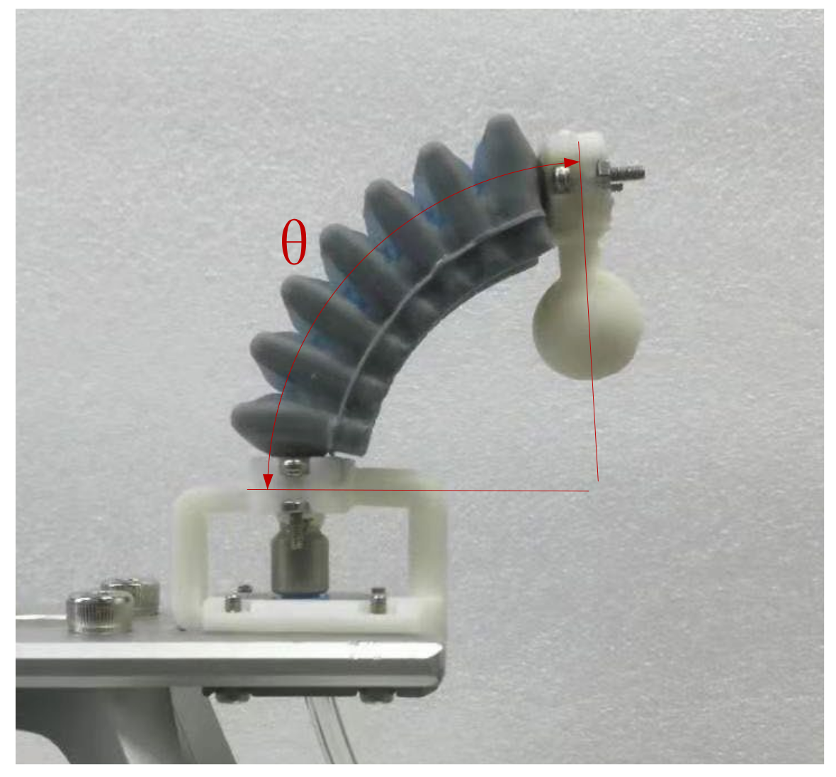
The definition of bending angle can be found in Section 2. In this experiment, the bending angle was also measured on the same test platform of tip force test. Photographs of the actuators were captured by the camera, and the bending angle value was measured through the photo. Because the geometric structure of the connectors is matched with that of the actuators, the bending angle θ can be measured using connectors at both ends.
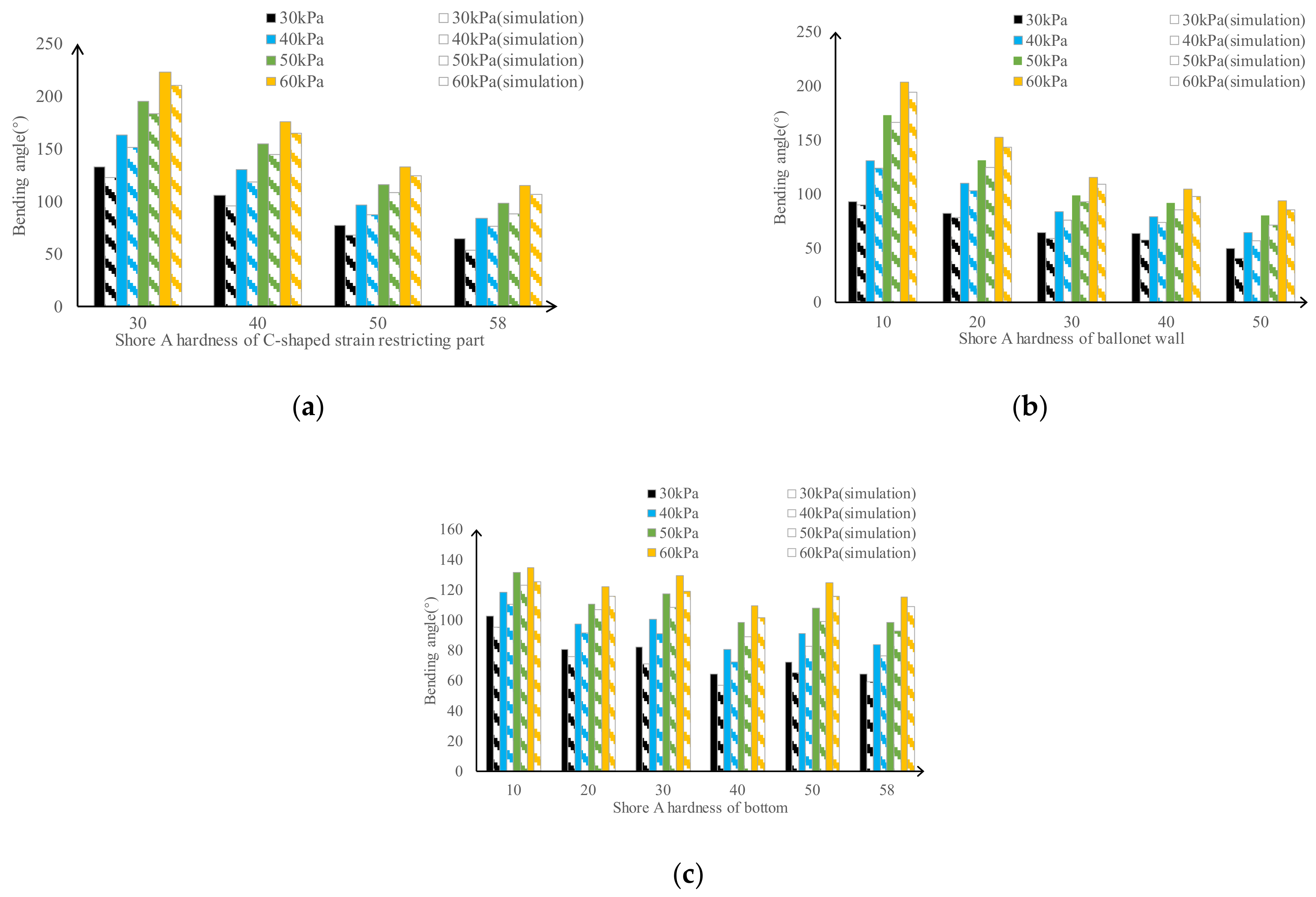
The experimental data for the bending angles of the actuators are presented in Figure 9. To have a better illustration, we merged the data from simulation listed in Figure 4 into Figure 9. The data suggest that the C-shaped strain-restricting part has less influence on the bending angles because this component mainly restricts lateral deformation and other redundant deformations. In general, the bending angle decreased with an increase in the hardness of the C-shaped strain-restricting part. Softer ballonets lead to a greater bending angle because it is the main actuating part, which is consistent with the results of the tip force. Regarding the effects of bottom hardness, generally, the tendency is that a softer bottom results in a greater bending angle. However, a certain amount of data are contrary to this tendency, which may be attributed to the fact that the bottom has little influence on free bending. Considering the previous tip force results of the bottom, a softer bottom helps to bend while restricting the exertion force, so a larger bending angle would not certainly represent a larger tip force. Therefore, it can be concluded that the bending angle is not the only criterion for evaluating the bending performance of the actuator. Both the tip force and bending angle should be considered.
The simulation data suggest that the FEM analysis results were consistent with the experimental results, and the tendency was basically the same. The simulated bending-angle data are approximately 10° smaller than the experimental results. This deviation may be due to the simulation settings and differences between the nominal and actual performances of the silicon rubbers.
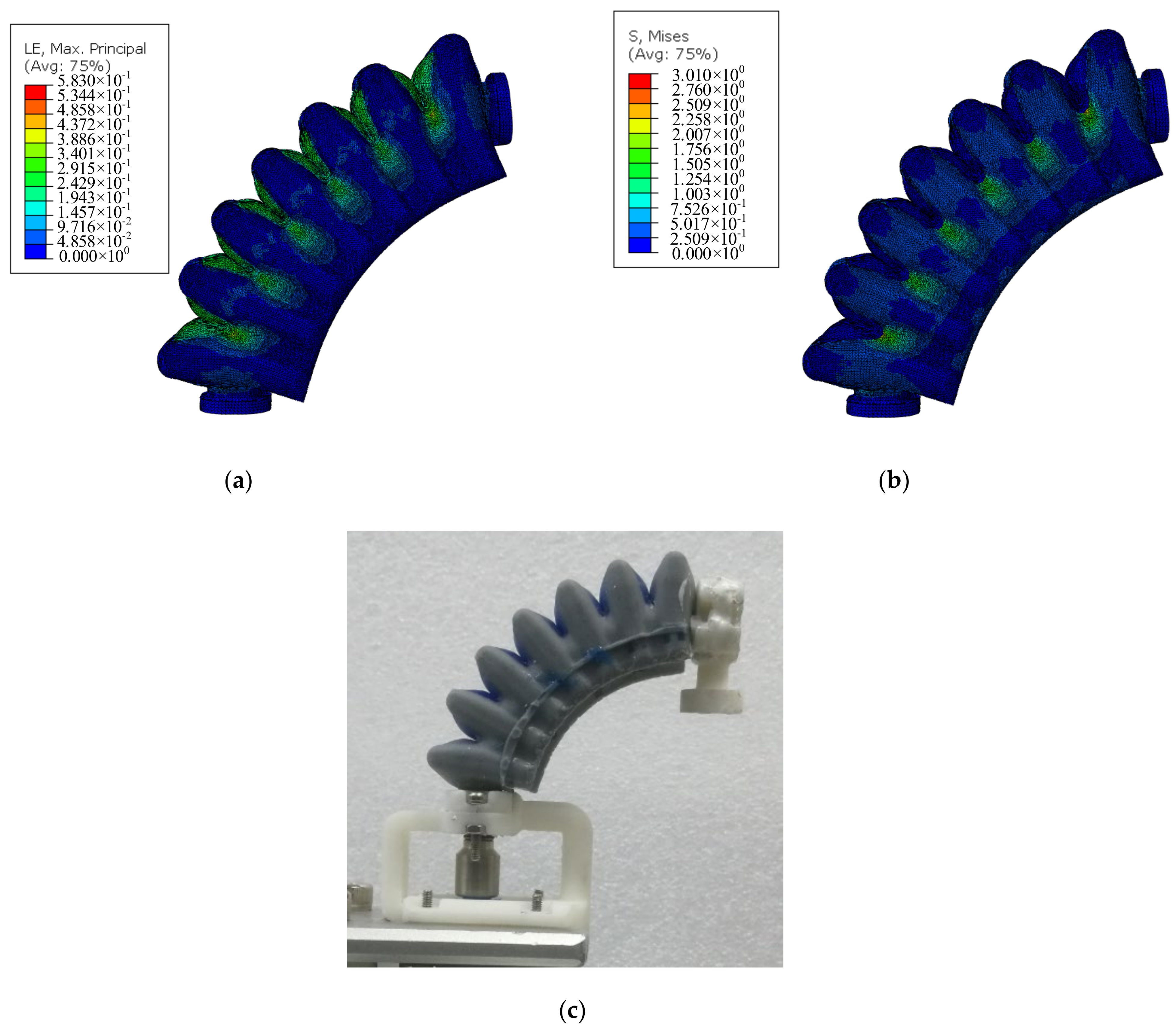
Moreover, we displaced the simulation result and the actual bending result in Figure 10. The result shows that bending behavior of the actuator “58-50-58” under 60 kPa pressure is analogous to that of actual actuator. The simulation results indicate that the region that undergoes the largest stress is located on the junction area of two ballonets in the C-shaped strain-restricting part, which is a region where rupture easily occurs according to practical test experiences. The largest strain appears at the ballonet wall and the junction area, which is consistent with the actual tendency. In summary, it can be seen that the simulation model that we constructed is correct which can provide a simulation pipeline for simulating the similar soft actuator structure, and for the bending angle test, we can finally obtain the optimized the material composition for different parts of the soft actuator according to the characteristics of its motion.

4.3. The Effectiveness of C-Shaped Strain-Restricting Part

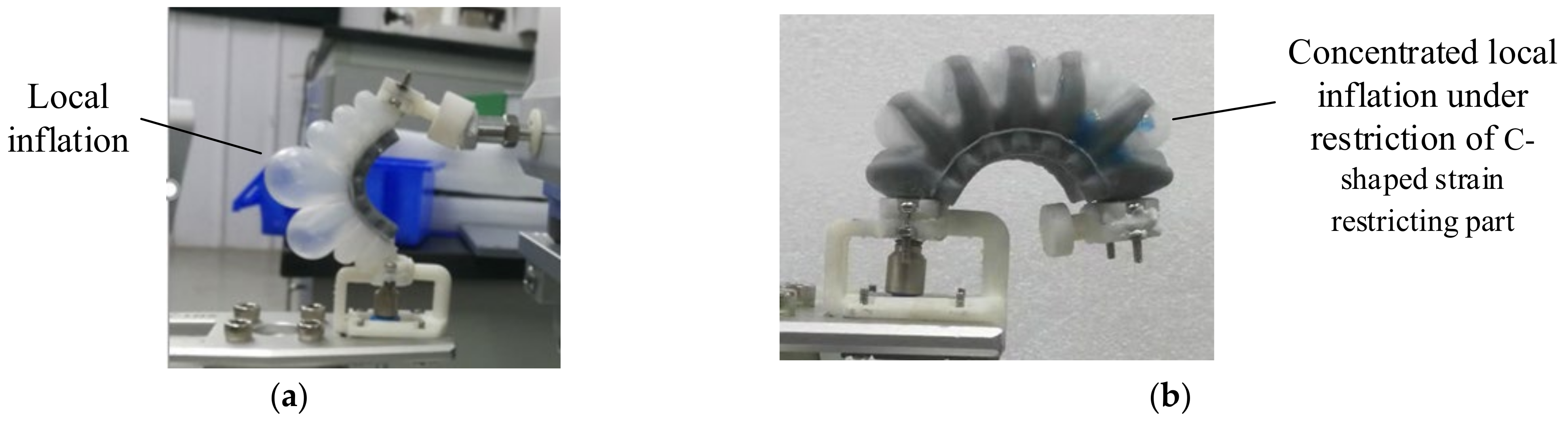
However, if the actuator is made of only one silicon rubber, a softer rubber would not lead to better results because local expansion or expansion would occur (shown in Figure 11), deteriorating the life and normal actuation of the actuator. In contrast, if a multi-silicon rubber structure of the actuator is applied, as shown in Figure 11b, the harder C-shaped strain-restricting part reduces lateral expansion and deformation. Although a softer ballonet wall (Shore A hardness of 10) may expand locally, this expansion is directed in the direction that aids the bending actuation. This comparison verified that the harder C-shaped strain-restricting part was beneficial for increasing the bending performance of the actuator.
Overall, for the three defined components of the actuator, a hardened C-shaped strain-restricting part (Shore A hardness greater than 50), softer ballonet wall, and harder bottom resulted in better bending performance of the actuator. A higher pneumatic pressure leads to a greater output tip force.

5. Conclusions

In this study, an actuator composed of silicon rubber with multiple hardness is designed and fabricated. The design of dividing the actuator into three components and using the corresponding silicon rubbers to fabricate them is beneficial for reducing redundant and unexpected deformations, thus increasing the bending performance of the actuator. The relatively harder C-shaped strain-restricting part, softer ballonet wall, and harder bottom contributed to a better actuator performance. The experimental results revealed that the degree of bending is an indication of the bending performance to some extent, but it is not the only criterion. The harder bottom part, which acts as a transmission medium for the tip force, helps the actuator to generate a greater tip force.
Some aspects of the work in this research need to be improved or added, such as optimizing the actuator structure, improving the simulation accuracy, and verifying the adhesion between different silicone rubbers.
The actuator design of this study provides a new design concept for pneumatic actuators that adopt a ballonet to actuate. If the three components of the actuator are fabricated through 3D printing or other manufacturing methods, many soft materials can be used to fabricate the actuator; thus, many designs may arise. In addition, this research provides a solution for improving the bending performance of pneumatic actuators wholly fabricated using silicon rubbers.

Author Contributions

Methodology, S.C. and X.J.; field investigation, S.C. and X.J.; data curation, S.C. and X.J.; writing—original draft preparation, S.C. and C.Z.; writing—review and editing, X.J., C.Z. and F.X. All authors have read and agreed to the published version of the manuscript.

Funding

This research received no external funding.

Institutional Review Board Statement

Not applicable.

Informed Consent Statement

Not applicable.

Data Availability Statement

Data are contained within the article.

Conflicts of Interest

The authors have no conflict of interest.

References

  1. Ilievski, F.; Mazzeo, A.D.; Shepherd, R.F.; Chen, X.; Whitesides, G.M. Soft robotics for chemists. Angew. Chem. Int. Ed. 2011, 123, 1930–1935. [Google Scholar] [CrossRef]
  2. Otake, M.; Kagami, Y.; Kuniyoshi, Y.; Inaba, M.; Inoue, H. Inverse kinematics of gel robots made of electro-active polymer gel. In Proceedings of the 2002 IEEE International Conference on Robotics and Automation, Washington, DC, USA, 11–15 May 2002. [Google Scholar]
  3. Brown, E.; Rodenberg, N.; Amend, J.; Mozeika, A.; Steltz, E.; Zakin, M.R.; Lipson, H.; Jaeger, H.M. Universal robotic gripper based on the jamming of granular material. Proc. Natl. Acad. Sci. USA 2010, 107, 18809–18814. [Google Scholar] [CrossRef] [Green Version]
  4. Lin, H.T.; Leisk, G.G.; Trimmer, B. GoQBot: A caterpillar-inspired soft-bodied rolling robot. Bioinspir. Biomim. 2011, 6, 026007. [Google Scholar] [CrossRef]
  5. Kellaris, N.; Gopaluni Venkata, V.; Smith, G.M.; Mitchell, S.K.; Keplinger, C. Pea-no-HASEL actuators: Muscle-mimetic, electrohydraulic transducers that linearly contract on activa-tion. Sci. Robot. 2018, 3, eaar3276. [Google Scholar] [CrossRef] [Green Version]
  6. Mao, Z.; Iizuka, T.; Maeda, S. Bidirectional electrohydrodynamic pump with high symmetrical performance and its application to a tube actuator. Sens. Actuators A Phys. 2021, 332, 113168. [Google Scholar] [CrossRef]
  7. Shepherd, R.F.; Stokes, A.A.; Freake, J.; Barber, J.; Snyder, P.W.; Mazzeo, A.D.; Cademartiri, L.; Morin, S.A.; Whitesides, G.M. Using explosions to power a soft robot. Angew. Chem. Int. Ed. 2013, 52, 2892–2896. [Google Scholar] [CrossRef]
  8. Marchese, A.D.; Katzschmann, R.K.; Rus, D. A Recipe for Soft Fluidic Elastomer Robots. Soft Robot. 2015, 315, 700–711. [Google Scholar] [CrossRef] [Green Version]
  9. Shui, L.; Zhu, L.; Yang, Z.; Liu, Y.; Chen, X. Energy efficiency of mobile soft robots. Soft Matter 2017, 13, 8223–8233. [Google Scholar] [CrossRef]
  10. Yoshida, S.; Morimoto, Y.; Zheng, L.; Onoe, H.; Takeuchi, S. Multipoint Bending and Shape Retention of a Pneumatic Bending Actuator by a Variable Stiffness Endoskeleton. Soft Robot. 2018, 5, 718–725. [Google Scholar] [CrossRef]
  11. Zhang, Y.F.; Zhang, N.; Hingorani, H.; Ding, N.; Wang, D.; Yuan, C.; Zhang, B.; Gu, G.; Ge, Q. Fast-Response, Stiffness-Tunable Soft Actuator by Hybrid Multimaterial 3D Printing. Adv. Funct. Mater. 2019, 29, 1806698. [Google Scholar] [CrossRef]
  12. Al-Rubaiai, M.; Pinto, T.; Qian, C.; Tan, X. Soft actuators with stiffness and shape modulation using 3D-printed conductive polylactic acid material. Soft Robot. 2019, 6, 318–332. [Google Scholar] [CrossRef]
  13. Akbari, S.; Sakhaei, A.H.; Panjwani, S.; Kowsari, K.; Serjouei, A.; Ge, Q. Multimaterial 3D Printed Soft Actuators Powered by Shape Memory Alloy Wires. Sens. Actuators A Phys. 2019, 290, 177–189. [Google Scholar] [CrossRef] [Green Version]
  14. Liu, J.A.-C.; Gillen, J.H.; Mishra, S.R.; Evans, B.A.; Tracy, J.B. Photothermally and magnetically controlled reconfiguration of polymer composites for soft robotics. Sci. Adv. 2019, 5, eaaw2897. [Google Scholar] [CrossRef] [Green Version]
  15. Zhang, Y.F.; Ng, C.J.X.; Chen, Z.; Zhang, W.; Panjwani, S.; Kowsari, K.; Yang, H.Y.; Ge, Q. Miniature Pneumatic Actuators for Soft Robots by High-Resolution Multimaterial 3D Printing. Adv. Mater. Technol. 2019, 4, 1900427. [Google Scholar] [CrossRef]
  16. Du Pasquier, C.; Chen, T.; Tibbits, S.; Shea, K. Design and Computational Modeling of a 3D Printed Pneumatic Toolkit for Soft Robotics. Soft Robot. 2019, 6, 657–663. [Google Scholar] [CrossRef]
  17. Byrne, O.; Coulter, F.; Glynn, M.; Jones, J.F.; Ní Annaidh, A.; O’Cearbhaill, E.D.; Holland, D.P. Additive Manufacture of Composite Soft Pneumatic Actuators. Soft Robot. 2018, 5, 726–736. [Google Scholar] [CrossRef]
  18. Chen, Y.; Li, Y.; Li, Y.; Wang, Y. Stiffening of soft robotic actuators—Jamming ap-proaches. In Proceedings of the 2017 IEEE International Conference on Real-time Computing and Robotics (RCAR), Okinawa, Japan, 14–18 July 2017; pp. 17–21. [Google Scholar]
  19. Mao, Z.; Kuroki, M.; Otsuka, Y.; Maeda, S. Contraction waves in self-oscillating polymer gels. Extrem. Mech. Lett. 2020, 39, 100830. [Google Scholar] [CrossRef]
  20. Mosadegh, B.; Polygerinos, P.; Keplinger, C.; Wennstedt, S.; Shepherd, R.F.; Gupta, U.; Shim, J.; Bertoldi, K.; Walsh, C.J.; Whitesides, G.M. Pneumatic networks for soft robotics that actuate rapidly. Adv. Funct. Mater. 2014, 24, 2163–2170. [Google Scholar] [CrossRef]
  21. Li, Y.; Chen, Y.; Ren, T.; Li, Y.; Choi, S.H. Precharged Pneumatic Soft Actuators and Their Applications to Untethered Soft Robots. Soft Robot. 2018, 5, 567–575. [Google Scholar] [CrossRef]
  22. Natividad, R.; Del Rosario, M., Jr.; Chen, P.C.; Yeow, C.H. A Reconfigurable Pneumatic Bending Actuator with Replaceable Inflation Modules. Soft Robot. 2018, 5, 304–317. [Google Scholar] [CrossRef]
  23. Heung, K.H.; Tong, R.K.; Lau, A.T.; Li, Z. Robotic Glove with Soft-Elastic Composite Actuators for Assisting Activities of Daily Living. Soft Robot. 2019, 6, 289–304. [Google Scholar] [CrossRef] [PubMed]
  24. Al-Ibadi, A.; Nefti-Meziani, S.; Davis, S. Active Soft End Effectors for Efficient Grasping and Safe Handling. IEEE Access 2018, 6, 23591–23601. [Google Scholar] [CrossRef]
  25. Fei, Y.; Wang, J.; Pang, W. A Novel Fabric-Based Versatile and Stiffness-Tunable Soft Gripper Integrating Soft Pneumatic Fingers and Wrist. Soft Robot. 2019, 6, 1–20. [Google Scholar] [CrossRef] [PubMed]
Figure 1. Structure of the pneumatic actuator.
Machines 10 00272 g001
Figure 2. Simulation model and boundary condition of the pneumatic actuator.
Machines 10 00272 g002
Figure 3. Definition of the bending angle of the actuator.
Machines 10 00272 g003
Figure 4. Simulation data of bending angle: (a) Simulation 1: the hardness of C-shaped strain-restricting part. (b) Simulation 2: the hardness of ballonet wall as variable. (c) Simulation 3: the hardness of bottom as variable.
Machines 10 00272 g004
Figure 5. The cross-section view of stress distribution of the actuator.
Machines 10 00272 g005
Figure 6. Fabrication of the actuator.
Machines 10 00272 g006
Figure 7. The test platform and experimental settings for measuring tip force: (a) The established test platform, the air pump is not shown. (b) Experimental settings for measuring tip force of the actuator.
Machines 10 00272 g007
Figure 8. Experimental data of actuator tip force: (a) The hardness of C-shaped strain-restricting part as variable. (b) The hardness of ballonet wall as variable. (c) The hardness of bottom as variable.
Machines 10 00272 g008
Figure 9. Experimental data and simulation data of bending angle: (a) The hardness of C-shaped strain-restricting part as variable. (b) The hardness of ballonet wall as variable. (c) The hardness of bottom as variable.
Machines 10 00272 g009
Figure 10. Experimental actuator bending and simulated bending. The hardness composition of the actuator is “58-50-58” and pneumatic pressure is 60kPa: (a) Simulation results that show the distribution of strain. (b) Simulation results that show the distribution of stress. (c) Actual bending of the actuator.
Machines 10 00272 g010
Figure 11. Description of function of hard C-shaped strain-restricting part: (a) Local expansion of actuator ballonet without hard C-shaped strain-restricting part. The composition of the shown actuator is “30-30-58”. (b) Hard C-shaped strain-restricting part is introduced to the actuator, making local expansion concentrate in the direction favorable for bending. The composition of the shown actuator is “58-10-58”.
Machines 10 00272 g011
Table 1. Material properties of silicon rubbers that used in the simulation.
MaterialModulus of Elasticity (Mpa)Poisson’s Ratio
Si-100.15170.47
Si-200.33780.47
Si-300.59290.47
Si-400.62050.47
Si-503.42530.47
Si-585.28080.47
Table 2. Material properties for 3 different simulation tests.
C-Shaped Strain-Restricting PartBallonet WallBottom
Simulation 1Si-30, Si-40, Si-50, Si-58Si-30Si-58
Simulation 2Si-58Si-10, Si-20, Si-30, Si-40, Si-50Si-58
Simulation 3Si-58Si-30Si-10, Si-20, Si-30, Si-40, Si-50, Si-58
Table 3. Silicon rubbers that used in this research.
Silicon RubberCooperationShore A Hardness
Bluesil RTV 3460Elkem58
Bluesil RTV 3039Elkem50
SORTA-Clear 40Smooth-On40
Dragon skin 30Smooth-On30
Dragon skin 20Smooth-On20
Dragon skin 10Smooth-On10
Publisher’s Note: MDPI stays neutral with regard to jurisdictional claims in published maps and institutional affiliations.

