Article

Research into the Impact of Spindle Speed and Feed Rate Changes on the Life of a Deep-Drilling Technology Tool

1
Faculty of Manufacturing Technologies with a Seat in Presov, Technical University of Kosice, Bayerova 1, 080 01 Presov, Slovakia
2
Faculty of Industrial Engineering, Robotics and Production Management, Technical University of Cluj-Napoca, Bulevardul Muncii nr. 103-105, 400641 Cluj-Napoca, Romania
*
Author to whom correspondence should be addressed.
Machines 2022, 10(4), 268; https://doi.org/10.3390/machines10040268
Submission received: 8 March 2022 / Revised: 25 March 2022 / Accepted: 6 April 2022 / Published: 8 April 2022
(This article belongs to the Special Issue Advances in Computer-Aided Technology)

Abstract

:
The drilling process in real production places ever-increasing demands on the length and accuracy of the holes made. The drilling of holes beyond a length-to-diameter ratio of 5–10 is called deep drilling. The aim of the research was to determine in detail the deep-drilling process input conditions, their impact on the stability of the cutting process and the degree to which the output requirements were achieved. The focus of the analysis was on how the monitored technological and physical impacts translate into achieving the required gun-drill life and the quality and dimensional accuracy of deep holes, as well as their overall impact on tool life. Based on the analysis, tests were conducted to verify the impact of individual parameters on tool life. The obtained results were then statistically evaluated and optimized. Drawing on the evaluated experimental results, solutions and procedures were proposed and implemented in the environment of a real operation. This research obtained the optimal values of the frequency of rotation and displacement to ensure maximum tool life while maintaining the efficiency of the production of drilled parts. At the same time, based on the research, a methodology and recommendations for deep-drilling technology were developed.

1. Introduction

The rapid development of new technologies and growing consumer demands mean that companies are trying to find new and more efficient ways of developing and researching their products and, thus, receive the retroactive economic benefits of production. Current technical progress and the application of specific solutions and innovations, thanks to which manufacturing companies can promptly improve established procedures and techniques, is expected to ensure high production efficiency. One such major technological operation is the drilling process [1].
The drilling of deep holes can be carried out in several ways: with a rotating workpiece or with a rotating tool, or with a tool rotating simultaneously with the rotating workpiece. Regardless of the drilling method, the basic principles of drilling and, moreover, the correct choice of cutting speed and feed rate, remain unchanged [2,3]. Successful chip formation and its removal from the cutting edge without damaging the tool and workpiece are, in principle, the most important factors influencing the quality of drilled holes [4]. Small-diameter holes are created using the technology of deep (gun-drill tool) drilling with the STS (single-tube system). An alternative to STS technology in cases where the drilling of a smaller production series is carried out and a specialized machine is not available is the ejector system [5,6]. Due to the state-of-the-art development of carbide monolithic tools, it is currently possible to make holes with smaller diameters with carbide screw augers featuring length-to-diameter ratios of up to 30 mm [7].
Both the design and the materials and coating used in deep-drilling technology have evolved [8]. The most recent solution is the design of gun-drill tool bodies with interchangeable cutting plates and interchangeable guide surfaces that provide the additional adjustment of dimensions using different washer widths [9]. Nevertheless, even with the use of the latest auger design, one of the most important conditions for maintaining a stable process is still relevant, namely the application of sufficient cutting fluid pressure to dissipate heat, to remove chips and to provide the cutting process with lubrication [10,11,12]. Other influences, such as the stability and accuracy of the machine, the properties of the machined material, the technological parameters and the use of a suitable tool also enter the process. All these factors affect the resulting process, which must, first and foremost, take into account the economic viability of production [13,14,15].
Several important authors from the worldwide scientific community address the issue of deep drilling. Hong J. et al. discuss a new method of data monitoring to estimate tool wear when making holes with the application of deep-drilling technology. The proposed monitoring method is a Gaussian regression process (GRS) based on a combination of force, torque and vibration signals that are extracted from a predefined segment. The results show that the accuracy of the tool wear estimate can be improved by the method proposed, which significantly outperforms other methods. Examples include linear regression and support vector regression [16]. In their publications, focusing on the force system and performance of the AlSi 1045 cutting steel drilling rig, Wang Y. et al. describe a drilling-force system created by integrating the forces on the main cutting edge by wear and outer diameter (OD) and mechanical equilibrium equations using a specific energy model, which consists of geometric parameters, machining parameters and material properties [17]. The researchers Zhang X. et al. are engaged in similar research and the development of high-quality augers with precisely controllable tool geometry. Through planned experiments, they experiment with the effects of changes in apex deviations on deviations in hole flatness. Through a series of FEM analyses and further measurements of the internal rolling of the machined holes, it was concluded that unbalanced cutting force components, applied to previously drilled holes due to inconsistent apex displacement, cause newly formed holes to deviate from the thin wall due to the greater material strain on the thin-walled side relative to the side with thick walls [18]. Studies of precision and surface roughness after deep drilling have been carried out by Kirsanov, S.V. and Babaev A.S., particularly on sintered carbide and water-resistant coating, which have higher wear resistance and ensure the lower surface roughness of drilled holes [19]. Based on their experimental results, Mann J.B. et al. conducted research in the field of drilling effects with overlapping controlled low-frequency modulation (MAM) and on the surface structures created after deep drilling [20]. With development of science and technology, the precision of the individual-component manufacturing process by deep-drilling technology increases together with the demand and constantly growing requirements for the tools and equipment needed for these operations. Therefore, Zhang K.L. researched the improvement in the accuracy and efficiency of these devices for real use in practice [21]. Schnabel D. et al. deal with deep-drilling processes resulting in small holes and openings, addressing especially the cooling and lubrication of the machined zone, which translates into longer tool life. In their publication, they model the movement of the cooling lubricant during the drilling process using the finite volume and the hydrodynamics of cooled particles. The results prove that changing the coolant close to the cut guarantees the desired cooling effect. The coolant is modeled by the smooth-pin hydrodynamics method and the end-point method is used to describe the points. This study also provides transient simulations of the hydrodynamics of the smooth particles, which show insufficient weight, and recommends replacing the cutting edges corresponding to the steady state and the results of the simulation of the final volume with a complete bore filled with coolant [22]. In their studies on point formation and wear behavior during the drilling process of titanium-coated forged steel S 48CS1V, Wang Y. et al. point out the complex wear of the hard carbide tool in the chip-forming tests performed on this steel. They claim that high alternative stress resulted in plastic strain, and that for atomic absorption, cold welding caused the carbide substrate grains to detach from the cobalt bond, thus causing the wear and tear of the tool [23]. In addition to turning and milling, drilling holes with augers is the most commonly used method in machining technology. A great number of machined holes is naturally reflected in the significant consumption of augers not only by individual companies, but also on a global scale. The choice of suitable types and auger design solutions therefore has a significant impact on the accuracy, efficiency and productivity of drilling, as well as on its economical use and consumption [24].
Drilling is a technological process resulting in circular cross-section holes. Their length depends on the design requirements and it is often necessary to drill holes with depths of up to five times their diameter [25]. This type of operation is referred to as deep drilling. Deep-drilling technology places greater emphasis on the cutting process than standard-hole (≤5D) drilling. To ensure a stable cutting process, as well as dimensional accuracy and quality standards, the following requirements must be met [26,27]:
(a)
The design of the tool must ensure good guidance of the tool in the hole and the geometry of the cutting part of the tool must ensure the formation of chips that can be easily removed from the hole area.
(b)
The tool must be sufficiently rigid to be able to drill efficiently in order to ensure that the drilling process runs smoothly.
(c)
The design of the tool must allow smooth chip removal from the hole area to ensure the smooth running of the drilling process and to prevent damage to the tool.
(d)
The technology must ensure a favorable relationship between cutting productivity and production economy through the appropriate choice of machine and other working conditions while adhering to all the required technical conditions for the accuracy of the drilled part.
(e)
The tool design must provide the prescribed dimensional accuracy, geometric shape and surface quality.
Monolithic long screw augers STS22 1130 and STS 22 1150 or augers with internal cooling STS 22 1154, manufactured with cutting fluid supply conduits, are used for drilling deep holes. Because the auger grooves fill quickly with chips, the augers need to be pulled out of the hole often to cool and remove the chips. This type of drilling is called intermittent drilling [28]. To avoid auger overload, the work cycle for augers ranging between 10 to 30 mm in diameter is selected according to the following established rules: the first bore is drilled to a depth of 2.5 to 4D; for subsequent bores, the hole is deepened gradually by 2D, 1.5D, 1D; and every subsequent attempt deepens the bore by 0.5D. Drills with an automatic work cycle operate in such a way that the auger spindle returns to its initial position at rapid traverse upon reaching a certain depth. After the chips have been emptied, it returns to the bottom of the hole at rapid traverse and continues drilling [29,30].
Due to difficult working conditions, the cutting ratios are reduced compared to those in short-hole drilling. Taking these values as a basis, for a hole depth of L = 3 to 15D, the cutting speed is reduced to 0.9 or further down, to 0.4, while the feed rates are reduced to 0.3–0.6 times of the basic values.
Carbide augers work similarly to HSS. They are manufactured up to a length of 30xD and they always feature internal cooling, thanks to which they do not require an intermittent work cycle. A precondition is a pilot hole, which must meet the hole accuracy requirements, usually in IT8. The depth of the pilot hole is given by at least 2D. Compared to HSS drills, TK drills can be used for drilling at higher speeds. The feed rate for TK drills can be set min. 5 times higher and set spindle speed min. 3 times higher compared to HSS, which depends on the manufacturer’s recommendations. The drills can also be cooled with oil mist (MQL), which is capable of ensuring good conditions for the stable cutting process [31].
The gun-drill tool is a single-wedge tool with internal flushing and external chip removal. It consists of three basic parts—the drill head, the drill tube, and the clamping shank. The tool has an outer straight V-shaped path and an inner conduit for the coolant and lubricant. The liquid flows through the tool axis, bypasses the cutting edge, carries away the emerging chips and washes them out of the hole through the external path. The drill head is typically carved from carbide, but in cases involving larger diameters, it can be made of steel with carbide elements (cutting edge and guide surfaces) bonded to them. The head has guide surfaces ground along the circumference, which are in contact with the drilled material during drilling. For larger diameters, replaceable elements (plates and guide surfaces) are widely used in current work. The forces acting on the tool during drilling strongly press the guide surfaces of the head against the wall of the drilled hole, so that the surface is slightly deformed, resulting in the high machining quality typical of all deep-drilling tools.
The aim of this research was to obtain the optimal values of the two main parameters influencing the tool life of deep-drilling technology, namely the feed rate and the tool rotation frequency. The first series of tests was performed to obtain the optimal spindle speed at a constant feed rate of 0.04 mm·min−1. The second series of tests was focused on finding the optimal value of the feed rate while maintaining a constant spindle speed of 2600 min−1.

2. Methodology

For the purposes of the experiment, the TBT gun drill 10.5 × 380 K15 shown in Figure 1 was used. It is a gun drill with a brazed carbide head, 10.5 mm in diameter and with a total length of 380 mm. The effective gun-drill length corresponds to the length of the hole on the test part, which is 280 mm. The carbide head type guide surfaces are of G design, complemented with a longitudinal groove on the main cutting edge, which helps to create chips. The carbide head is coated with TiAlN coating, which increases the auger’s life. The smooth clamping shank is 20 mm in diameter and is designed for clamping in a hydraulic clamp. The selected gun-drill tool is clamped in a Schunk hydro clamp of TENDO ES type. Clamping is carried out directly in the connection cone of the clamp.
To present and analyze the input conditions, an Ishikawa diagram was constructed, as shown in Figure 2. The main axis of the diagram represents the main problem and the individual influences that affect the tool life during the deep-drilling process. Based on the aforementioned factors influencing tool life, the individual effects in this diagram were verified under real engineering operation. The main factors affecting tool life in deep-drilling are the tool, the workpiece material, the tool geometry, the machine, the clamping and the coolant.
Tests of the gun-drill tool life were performed in real production in a plant. The series of tests verified the technological and technical recommendations of the gun-drill manufacturer for a stable cutting process on a given part using deep-drilling technology.

2.1. Experimental Machinery

Testing was carried out under the automotive production conditions at the production line. The machine used for testing in the real production process was a thickness planer and boring center with a portal loader from CZ-Tech Celakovice of the ZAH720 type. Two heads were used on the ZAH720 machine, as shown in Figure 3; the right head was designed for VDI clamping and the other for Bolt-one. The tool holders used were from ALGRA. Electromechanical turrets of the TAN series are designed for installation on CNC lathes. They are used for clamping dovetail toolholders according to VDI 3425 for use in the automatic positioning of toolholders consisting of a solid base and a rotating head made of hardened ground steel. The cooling of the machining center tools is ensured by a system of devices, which consists of a low-pressure pump, a high-pressure pump, a filter, and a small-metal-particle magnetic filter. The coolant pump provides the pressure necessary to cool, lubricate and clean all chips off the tools. A wall-plus pump was used for these needs, supplying a coolant pressure of 18 bar at a flow rate of 10.5 L/min. Its power was sufficient for standard cooling of the turning tools and of the pilot auger. A Grundfos MTS high-pressure pump was used to cool the gun-drill tool.

2.2. Parameters of the Test-Part Selection

The transmission input shaft shown in Figure 4 was selected as a test part, with a lubrication hole 10.5 mm in diameter and 280 mm long. The deep-drilling tests were performed on the shaft of a six-speed DSG gearbox. Deep-hole drilling consists of drilling a 240 millimeter-long hole 10.5 mm in diameter. This was a lubrication hole, the diameter of which was also chosen with regard to the requirement of relieving the shaft. A vertical lubrication hole with a diameter of 3 mm, located at the end of the shaft, must be smoothened after drilling due to formation of sharp edges up to 10.5 mm in diameter. For this reason, the drilling method was adapted to drill a diameter of 10.5 mm to full extent before drilling a perpendicular hole with a diameter of 3 mm and again applying a drilling cycle to smoothen the D3 hole with the gun-drill. At this point, increased wear on the side edge of the cannon auger occurred, as this was an intermittent cut.
The material used for the part selected to test the deep-drilling process complied with the company standard. With its composition and properties, the material resembled the 16MnCr5 and EN 10184. The chemical composition, according to the company standard, is presented in Table 1.
The STS 14220 material is a high-grade structural steel for cementation, which is well thermoformable. It is well machinable and weldable after soft and cold annealing. This steel is used for the production of machine parts with the possibility of refining up to diameters of 35 mm for cementation with high core strength, with the use for the production of shafts, gears, camshafts or gear couplings. This semi-finished product is supplied as a form of die forging.

2.3. Pilot-Hole Drilling

When using a gun-drill tool on conventional machines, it is necessary to drill a pilot hole as a guide, the length of which must be between 1 and 1.5 times the gun-drill diameter. For correct guidance, the hole must be within a D8 tolerance. The pilot hole is usually drilled at a greater depth, where the carbide auger has a significantly higher feed rate and, thus, reduces machining time. For a specific part, the gun drill is designed with respect to the given hole profile and the design of the auger is more graded. The pilot gun-drill tool Carbide 10.5/14.5, shown in Figure 5, is made of K40UF carbide from Konrad Friedrichs.

3. Statistical Evaluation and Optimization

3.1. Dependence of the Number of Drilled Holes up to the Moment of Tool Damage When Changing the Speed-Constant Feed Rate

The manufacturer-recommended values were used to test the technological parameters of a given part of the transmission shaft, with the cutting speed ranging from 70 to 100 m·min−1 for the given workpiece material. Figure 6 shows a plotted representation of the course of the number of drilled holes up to the moment the tool was damaged at different speeds and a constant feed rate of 0.04 mm·min−1.
The cutting speed of 70–100 m·min−1 represents the spindle speed, which ranged from 2100 to 3000 min−1. The selected spindle test range speed was 2400–2900 min−1. The tests were performed on a randomly selected gun-drill tool, while new augers and those that had been re-ground several times were excluded. Figure 7 shows the dependence of the number of drilled holes up to the moment of the tool damage and the length of the drilling time on the tool spindle speed.
The resulting values of the number of holes drilled up to the moment the tool was damaged and, thus, the life of the gun-drill tool under different speeds, show a significantly decreasing service life at speeds above 2700 min−1, as shown in Figure 7. The speed of 2700 min−1 corresponded to the cutting speed of 90 m·min−1. This value seems to be the most suitable both in terms of the tool life and in terms of the operation time; at the cutting speed of 90 m·min−1, the length of the drilling operation was 82 s.

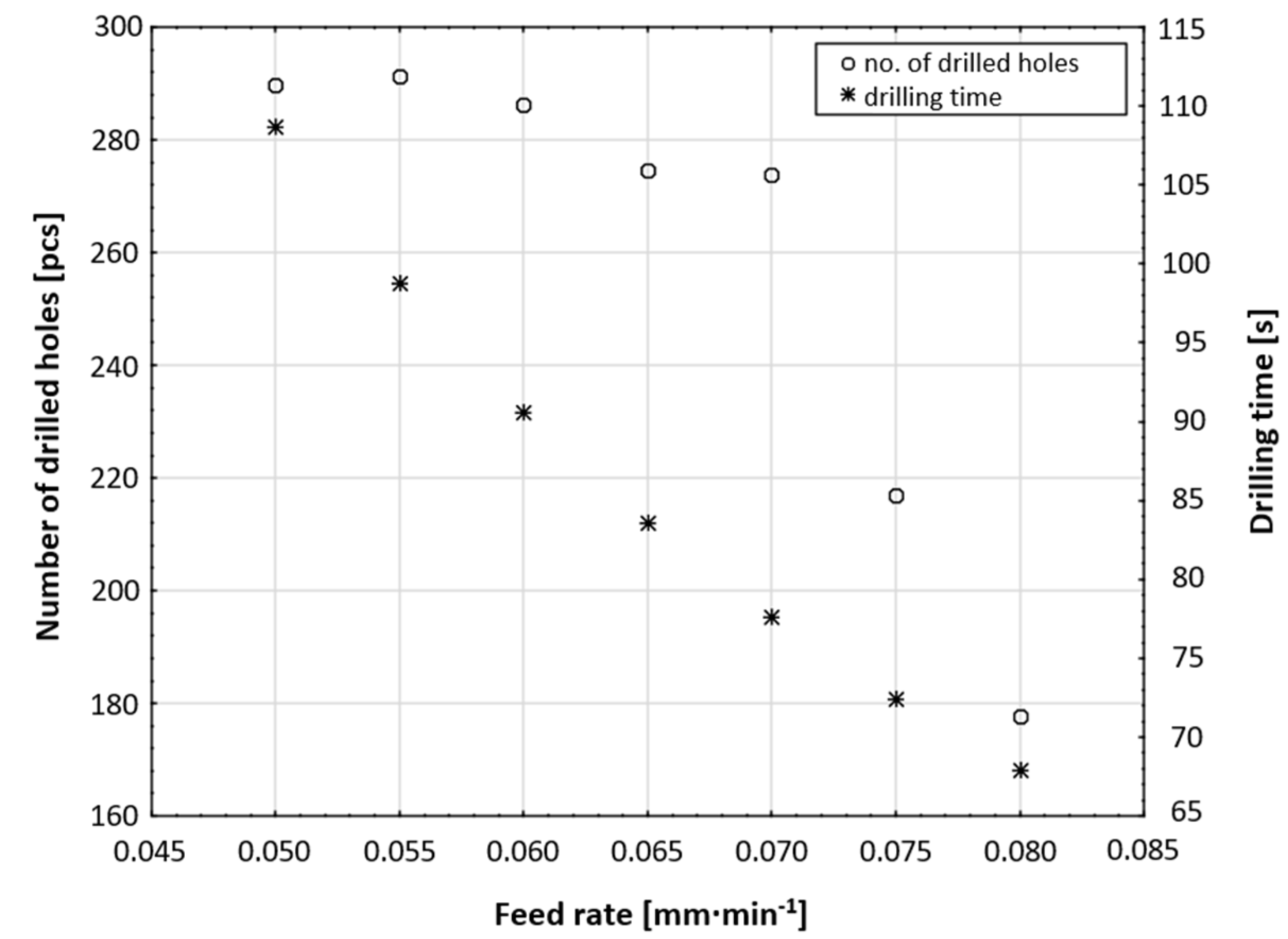
3.2. Dependence of the Number of Drilled Holes up to Moment of Tool Damage When Changing the Feed Rate-Constant Speed

For testing the technological parameters on the selected test part, the speed was also based on the values recommended by the manufacturer, while the feed rate for the given workpiece material was given in the range of 0.03–0.06 mm·min−1. This range was significantly lower than the range already used at the thickness planer. Feed rate values of 0.065 mm·min−1 were used as a standard. A test interface of 0.05–0.08 mm·min−1 was chosen for the testing. A constant value of 2600 min−1 was chosen for the speed.
Figure 8 and Figure 9 show plotted dependencies representing the number of holes drilled up to the moment the tool was damaged due to a change in the feed rate, as well as both the dependence of the number of holes drilled up to the moment of tool damage and the duration of the drilling operation on the change in feed rate.
The resulting values of the number of holes drilled up to the moment of damage to the gun-drill tool at different feed rates showed a significantly decreasing tool life at feed rates above 0.07 mm·min−1. The values of the number of holes drilled up to the moment the tool was damaged as a function of the feed are shown in Figure 9. In the tests, the feed rate of 0.55 mm·min−1 resulted in the longest gun-drill tool life, but the drilling time was 98.8 s, which is economically inefficient. In light of the economic efficiency of the deep-drilling operation, a value of 0.07 mm·min−1 appears to be the most suitable feed-rate value, with the operation lasting 82 s in this case.
The reduction in the number of holes drilled by increasing the feed was due to poorer chip removal from the tool and the consequent increase in tool temperature. The heat generation raised the temperature above the melting point of the alloying elements (e.g., Co and W) and the consequent mechanical properties, hardness and chemical wear resistance of the drill bit decreased dramatically due to the peeling of the alloying elements. Heat shock generated vertical or oblique cracks on the blade. These cracks widened and merged and, subsequently, broke the blade.

3.3. Statistical Evaluation and Optimization of the Dependence of the Auger Life at a Constant Feed Rate and Different Spindle Speeds

Figure 10 and Figure 11 show a comparison between the plotted number of holes drilled up to the moment of tool damage and the speed used in the experiment. The results of the comparisons subject to the specified parameters are subsequently presented in Table 2 and Table 3, which compare the obtained measurement results based on the number of drilled holes up to the moment of tool damage in terms of the change in experimental speed.
The value of the achieved level of significance of the Kruskal–Wallis variance analysis (p = 0.0008) makes it possible to state that there was a significant relationship between the speed and the number of drilled holes up to the moment of tool damage, with a significance level of 5%. In other words, speed has a statistically significant effect on tool life. A closer analysis of the multiple comparisons of the p values shows that there was a statistically significant difference between the number of holes drilled up to the moment of tool damage at: 2900 min−1 and 2400 min−1; 2900 min−1 and 2500 min−1; 2900 min−1 and 2600 min−1; and 2900 min−1 and 2700 min−1, respectively. To analyze the dependence of the number of drilled holes up to the moment of tool damage on speed, four different models were considered (Table 4), indicating their basic characteristics.
A plotted representation of the individual models examining the dependence of the number of holes drilled up to the moment of tool damage on speed, according to Table 4, is shown in Figure 12.
The quadratic model was chosen for the resulting analysis, which is shown in Figure 13, since the highest value of the adjusted determination index demonstrated the ability of the model to describe the data. The resulting general expression of the model is as follows:
a + b v + c v 2
where a is the absolute term, v is the speed, b is the linear term and c is the quadratic term.
1324.217 + 1.3334511 v 0.000269 v 2
The numerical values of the individual terms are given in Table 5. A plotted representation of the quadratic model in the ranges of the speeds used is shown in Figure 14.
In general, we obtain stationary points if we set the first derivation of the dependence function to zero:
dv 1324.217 + 1.3334511 v 0.000269 v 2 = 0
1.3334511 0.000538 v = 0
A plotted representation of the first derivation of the investigated function is shown in Figure 15, presenting the course of the first derivation of the number of drilled holes up to the moment of tool damage and speed change.
By solving the following equation (Solve (1.3334511 − 0.000538v = 0, v)) we arrive at the stationary point:
v 2478.533643122677
By inserting the value of the stationary point into the original dependence of the number of drilled holes up to the moment of tool damage depending on the change in speed, we obtain the value of the local function maximum sought (due to the fact that the second derivation of the function <0), that is to say, the number of drilled holes up to the moment of tool damage at a speed of 2478.53 min−1:
328.2847064044704 ,   v 2478.5336431226765

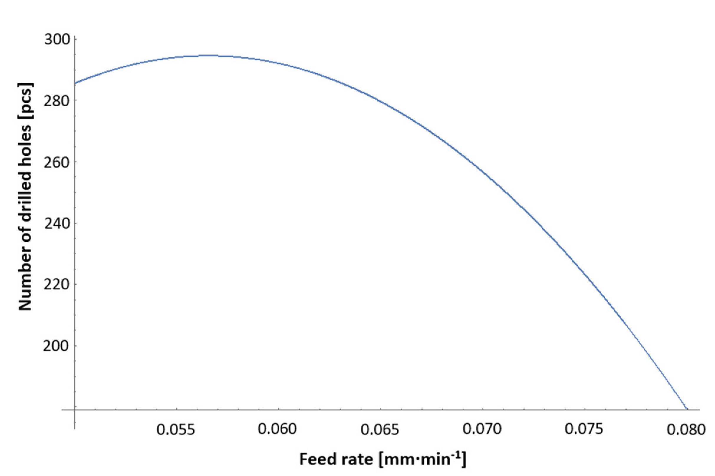
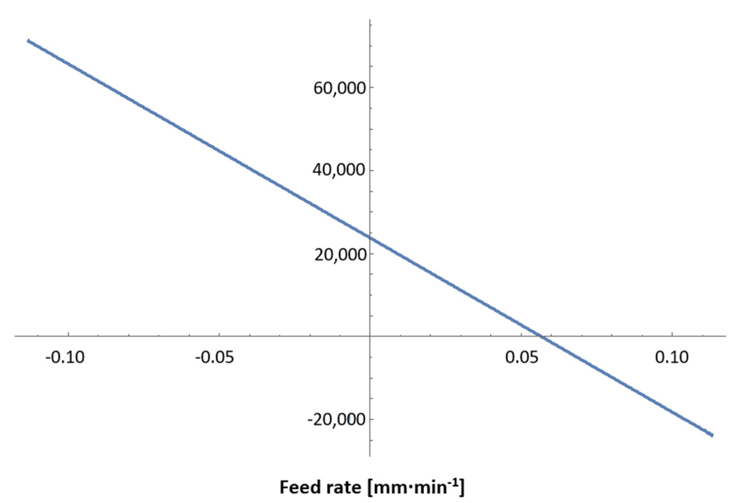
3.4. Statistical Evaluation and Optimization of the Dependence of the Number of Holes Drilled up to the Moment of Tool Damage When Changing the Feed Rate at a Constant Speed

Figure 16 and Figure 17 show a graph illustrating a comparison of the number of holes drilled and the drilling time up to the moment of tool damage under the different feed rates used in the experiment. The results of the comparisons subject to the specified parameters are subsequently presented in Table 6 and Table 7, which compare the measurement results obtained based on the number of holes drilled up to the moment of tool damage in terms of the changed experimental feed rate.
The value of the achieved level of significance of the Kruskal–Wallis variance analysis (p = 0.0008) makes it possible to state that there was a significant relationship between the speed and the number of holes drilled up to the moment of tool damage, with a significance level of 5%. In other words, feed rate has a statistically significant effect on tool life. A closer analysis of the multiple comparisons of p values shows that there was a statistically significant difference between the number of holes drilled at of the following feed rates: 0.075 mm·min−1 and 0.05 mm·min−1; 0.075 mm·min−1 and 0.055 mm·min−1; and 0.075 mm·min−1 and 0.06 mm·min−1, respectively. Furthermore, this also applied to the following feed rates: 0.08 mm·min−1 and 0.05 mm·min−1; 0.08 mm·min−1 and 0.055 mm·min−1; 0.08 mm·min−1 and 0.06 mm·min−1; 0.08 mm·min−1 and 0.065 mm·min−1; and 0.08 mm·min−1 and 0.07 mm·min−1, respectively.
To analyze the dependence of the number of drilled holes on the feed rate, five different models were considered, as presented in Table 8, which provides their basic characteristics.
A plotted representation of the individual models according to Table 8 is shown in Figure 18.
The quadratic model was chosen for the resulting analysis, since the highest value of the adjusted determination index demonstrated the ability of the model to describe the data. The resulting general expression of the model is as follows:
a + b f + c f 2
where a is the absolute term, f is the feed rate, b is the linear term and c is the quadratic term.
The numerical values of the individual terms are given in Table 9, which lists the basic parameters of the quadratic model of the dependence of the number of holes drilled up to the moment of tool damage on the feed rate.
A plotted representation of the quadratic model in the range of the feed rates used is shown in Figure 19.
In general, we obtain stationary points if we set the first derivation of the dependence function to zero:
df 376.414 + 23736.19 f 209904.8 f 2 = 0
23736.19 419809.6 f = 0
A plotted representation of the first derivation of the investigated function is shown in Figure 20.
By solving the following Equation (10), we arrive at the stationary point:
f 0.056540369729515476
By inserting the value of the stationary point into the original dependence of the number of holes drilled up to the moment of tool damage on the feed rate, the value of the local function maximum sought is obtained (due to the fact that the second derivation of the function <0), that is to say, the number of the holes drilled up to the moment of tool damage at the feed rate of 0.0565 mm·min−1 is:
294.6121792850139 , f 0.056540369729515476

4. Recommended Conditions for Drilling with Gun-Drill Tool on a CNC Machine Using a Pilot-Hole Guide

Currently, there is a great demand in the engineering industry for a radical reduction in the preparation time and rationalization of the development process for the rapid application of new methods and techniques. Global competition and increasing demands in the field of product life require not only the modernization of production capacities, but also new, innovative methods ensuring the smooth running of technological means. One such method is the deep-drilling process, which is used when it is necessary to create holes with depths of up to ten times their diameters. Based on long-term tests and the statistical processing of technological and physical parameters, it is possible to establish the following recommendations for deep-drilling technology.
Gun drill of the L10.5 × 380 DIN 1835A 20 × 50 CHIP GROOVE type.
Procedure for inserting a gun-drill tool:
  • Stop the auger before the hole-rapid traverse.
  • Slowly insert the auger at a counter-clockwise speed (or without speed, at a maximum of 50 min−1) with cooling.
  • Once the auger has been inserted into the pilot hole, switch on full speed and cooling.
  • Start the drilling process.
  • When the full depth of the hole is reached, switch off the feed rate, stop the spindle speed with a delay and switch off the high-pressure cooling with a small delay.
  • Slide the auger out of the hole at rapid traverse.
Testing conditions and recommendations for maximizing service life in terms of the speed and feed-rate settings:
  • A feed rate of 0.07 mm·min−1.During the testing of the stable service life at the given feed rate, in the event of a change in input conditions (deviation in the workpiece material), it is recommended to reduce the feed-rate value to 0.06 mm·min−1.
  • A speed of 2700 min−1. During the testing of the stable service life at the given speed, in the event of a change in input conditions (deviation in the workpiece material), it is recommended to reduce the speed value to 2600 min−1.
Conditions specified by the manufacturer and verified by testing:
  • Coolant pressure >30 bar; the manufacturer recommends that it be above 35 bar.
  • Emulsion percentage >9% (the manufacturer recommends over 12%).
  • The pilot hole must be 1–1.5xD long.
  • The pilot-hole tolerance must be in H8.
  • The pilot-hole apex angle should be >140°.
  • The cutting speed varies, depending on the workpiece material used (the tested cutting speed, which showed the highest service life values, was 90 m·min−1).
  • The feed rate varies, depending on the workpiece material used (the material tested by us showed the highest tool life at a feed rate of 0.07 mm·min−1).
  • The pilot-hole drilling deviation should be <0.02 mm in all axes.
  • Gun-drill tool deviation <0.02 mm in all axes.
  • The minimum length of the drilling part of the gun-drill tool should be 1.5xD.
  • Fixed clamping in the hydraulic clamp.
In order to successfully maximize the service life of gun-drill tools, no limit deviations from the prescribed properties and composition of the material being machined may occur. The service life of the augers is also affected by the functional condition of the machine tools–spindle backlash, machine vibration, guide backlash and leaks in the fluid supply conduit, as well as the consequent loss of pressure.

5. Conclusions

Through measurement, the general recommendations of the manufacturer were verified and proven to be informative in real operation conditions. Based on extensive tests and the resulting statistically processed data, the parameters were correlated with the subsequent methodology for deep-drilling technology. Various technological parameters were tested in a series of tests performed during real engineering production, which were subjected to statistical evaluation. As part of the statistical analysis of the dependences of the monitored input factors, such as the feed rate and speed, a nonlinear regression analysis was performed in order to identify the most suitable optimization function. The quadratic function was chosen as the most suitable function based on the criterion of the best possible description of the experimentally obtained results, while the adjusted determination index was chosen as the criterion for the dependence of the tool life on the feed rate. Based on this dependence, it reached the value of 77.25%. Thus, it can be stated that the chosen model can explain 77.25% of the variability in the measured values. The optimization itself was based on the quadratic optimization function, reaching its local maximum at a feed rate of 0.0565 mm·min−1, with the predicted value of the number of holes drilled up to the moment of tool damage being 294.61. For the analysis of the dependence of the tool life on the speed, the quadratic function was chosen again as a nonlinear regression analysis based on the criterion of the adjusted determination index as the ability of the model to explain the variability in the measured data. Based on this dependence, the value of the adjusted determination index was 98.24%; therefore, the model could not explain the remaining 1.76% of the measured data. Based on the analysis, the optimization function reached its maximum at a speed of 2478.334 min−1, with the predicted value of the number of holes drilled up to the moment of tool damage being 328.285.
Further research will examine other parameters, such as temperature and pressure of the coolant, with a comparison of the selection of carbide tools for making holes using deep-drilling technology.

Author Contributions

M.P. processed and evaluated the data and wrote the paper; M.K. conceived and designed the experiments; J.P. performed the experiments and measurements; S.D.G. and V.C. performed the data curation. All authors have read and agreed to the published version of the manuscript.

Funding

This research received no external funding.

Data Availability Statement

Not applicable.

Acknowledgments

This paper has been elaborated in the framework of the project KEGA 038TUKE-4/2021, VEGA 1/0051/20 and project APVV-18-0316.

Conflicts of Interest

The authors declare no conflict of interest. The founding sponsors had no role in the design of the study; in the collection, analyses, or interpretation of data; in the writing of the manuscript; or in the decision to publish the results.

References

  1. Neo, D.W.K.; Liu, K.; Kumar, A.S. High throughput deep-hole drilling of Inconel 718 using PCBN gun drill. J. Manuf. Processes 2020, 57, 302–311. [Google Scholar] [CrossRef]
  2. Strodick, S.; Berteld, K.; Schmidt, R.; Biermann, D.; Zabel, A.; Walther, F. Influence of cutting parameters on the formation of white etching layers in BTA deep hole drilling. Tech. Mess. 2020, 87, 674–682. [Google Scholar] [CrossRef]
  3. Ozerkan, H.B.; Cogun, C. Electrochemical small diameter deep hole drilling of powder metal steel. Trans. Famena 2020, 44, 47–58. [Google Scholar] [CrossRef]
  4. Vasilko, K.; Murcinkova, Z. Experimental study of chip shapes in grinding by unique quick stop method and the ground subsurface layers micro-hardness. J. Mech. Sci. Technol. 2019, 33, 1341–1347. [Google Scholar] [CrossRef]
  5. Zhang, Z.; Liu, S.; Zhang, Y.; Wang, C.H.; Zhang, S.; Yang, Z.; Xu, W. Optimization of low-power femtosecond laser trepan drilling by machine learning and a high-throughput multi-objective genetic algorithm. Opt. Laser Technol. 2022, 148, 107688. [Google Scholar] [CrossRef]
  6. Steininger, A.; Bleicher, F. In-process monitoring and analysis of whirling motions in boring and trepanning association deep drilling. MM Sci. J. 2019, 2019, 3122–3128. [Google Scholar] [CrossRef]
  7. Arrospide, E.; Bikandi, I.; Larranaga, I.; Cearsolo, X.; Zubia, J.; Durana, G. Harnessing deep-hole drilling to fabricate air-structured polymer optical fibres. Polymers 2019, 11, 1739. [Google Scholar] [CrossRef] [Green Version]
  8. Garza, C.; Das, R.; Shterenlikht, A.; Pavier, M. Measurement of assembly stress in composite structures using the deep-hole drilling technique. Compos. Struct. 2018, 202, 119–126. [Google Scholar] [CrossRef] [Green Version]
  9. Li, L.; He, N.; Hao, X.Q.; Yang, Y.F. Deep-hole gun drilling mechanics model of Ti6Al4V alloy based on Johnson and Cook flow stress model. Int. J. Adv. Manuf. Technol. 2019, 104, 4497–4508. [Google Scholar] [CrossRef]
  10. Haddag, B.; Nouari, M.; Moufki, A. Experimental analysis of the BTA deep drilling and a new analytical thermomechanical model for assessment of cutting forces and BTA drill design. Int. J. Adv. Manuf. Technol. 2020, 106, 455–469. [Google Scholar] [CrossRef]
  11. Panda, A.; Duplak, J. Comparison of theory and practice in analytical expression of cutting tools durability for potential use at manufacturing of bearings. Appl. Mech. Mater. 2014, 616, 300–307. [Google Scholar] [CrossRef]
  12. Dobransky, J.; Mikus, R.; Ruzbarsky, J. Comparison of cooling variants by simulation software. Mater. Technol. Qual. Assur. 2013, 801, 75–80. [Google Scholar] [CrossRef]
  13. Gao, T.; Li, C.H.; Wang, Y.; Liu, X.; An, Q.; Li, H.N.; Zhang, Y.; Cao, H.; Liu, B.; Wang, D.; et al. Carbon fiber reinforced polymer in drilling: From damage mechanisms to suppression. Compos. Struct. 2022, 286, 115232. [Google Scholar] [CrossRef]
  14. Lu, H.; Zhao, X.; Tao, B.; Ding, H. A state-classification approach for light-weight robotic drilling using model-based data augmentation and multi-level deep learning. Mech. Syst. Signal Processing 2022, 167, 108480. [Google Scholar] [CrossRef]
  15. Bornschlegel, B.; Haasler, D.; Finger, J.; Grizmann, D.; Trautz, M.; Gillner, A. Deep drilling of structural timber with high power ultrashort pulsed laser radiation. J. Laser Micro Nanoeng. 2020, 15, 195–203. [Google Scholar] [CrossRef]
  16. Hong, J.; Zhou, J.H.; Chan, H.L.; Zhang, C.; Xu, H.; Hong, G.S. Tool condition monitoring in deep hole gun drilling: A data-driven approach. In Proceedings of the 2017 IEEE International Conference on Industrial Engineering and Engineering Management (IEEM), Singapore, 10–13 December 2017; pp. 2148–2152. [Google Scholar] [CrossRef]
  17. Wang, Y.; Jia, W.; Zhang, J. The force system and performance of the welding carbide gun drill to cut AISI 1045 steel. Int. J. Adv. Manuf. Technol. 2014, 74, 1431–1443. [Google Scholar] [CrossRef]
  18. Zhang, X.; Leong, T.G.; Liu, K.; Anantharajan, S.K. Effect of apex offset inconsistency on hole straightness deviation in deep hole gun drilling of Inconel 718. Int. J. Mach. Tools Manuf. 2018, 125, 123–132. [Google Scholar] [CrossRef]
  19. Kirsanov, S.V.; Babaev, A.S. The study of deep holes accuracy and surface roughness after gun drilling. In Proceedings of the 2014 International Conference on Mechanical Engineering, Automation and Control Systems (MEACS), Tomsk, Russia, 16–18 October 2014; pp. 1–4. [Google Scholar] [CrossRef]
  20. Mann, J.B.; Saldana, C.; Guo, Y.; Yeung, H. Effects of controlled modulation on surface textures in deep-hole drilling. SAE Int. J. Mater. Manuf. 2013, 6, 24–32. [Google Scholar] [CrossRef] [Green Version]
  21. Zhang, W.; He, F.; Xiong, D. Gundrill life improvement for deep-hole drilling on manganese steel. Int. J. Mach. Tools Manuf. 2004, 44, 327–331. [Google Scholar] [CrossRef]
  22. Schnabel, D.; Oezkaya, E.; Biermann, D.; Eberhard, P. Modeling the motion of the cooling lubricant in drilling processes using the finite volume and the smoothed particle hydrodynamics methods. Comput. Methods Appl. Mech. Eng. 2018, 329, 369–395. [Google Scholar] [CrossRef]
  23. Wang, Y.; Yan, X.; Li, B.; Tu, G. The study on the chip formation and wear behavior for drilling forged steel S48CS1V with TiAlN-coated gun drill. Int. J. Refract. Met. Hard Mater. 2012, 30, 200–207. [Google Scholar] [CrossRef]
  24. Wegert, R.; Guski, V.; Mohring, H.C.; Schmauder, S. Temperature monitoring in the subsurface during single lip deep hole drilling. Tech. Mess. 2020, 87, 757–767. [Google Scholar] [CrossRef]
  25. Aized, T.; Amjad, M. Quality improvement of deep-hole drilling process of AISI D2. Int. J. Adv. Manuf. Technol. 2019, 69, 2493–2503. [Google Scholar] [CrossRef]
  26. Arunkumar, N.; Thanikasalam, A.; Sankaranarayanan, V.; Senthilkumar, E. Parametric optimization of deep-hole drilling on AISI 1045 steel and online tool condition monitoring using an accelerometer. Mater. Manuf. Processes 2018, 33, 1751–1764. [Google Scholar] [CrossRef]
  27. Chu, N.H.; Nguyen, D.B.; Ngo, N.K.; Nguyen, V.D.; Tran, M.D.; Vu, N.P.; Ngo, Q.H.; Tran, T.H. A new approach to modelling the drilling torque in conventional and ultrasonic assisted deep-hole drilling processes. Appl. Sci. 2018, 8. [Google Scholar] [CrossRef] [Green Version]
  28. Han, C.; Luo, M.; Zhang, D.H.; Wu, B.H. Iterative learning method for drilling depth optimization in peck deep-hole drilling. J. Manuf. Sci. Eng. Trans. ASME 2018, 140, 121009. [Google Scholar] [CrossRef]
  29. Valicek, J.; Harnicarova, M.; Hlavaty, I.; Grznarik, R.; Kusnerova, M.; Hutyrova, Z.; Panda, A. A new approach for the determination of technological parameters for hydroabrasive cutting of materials. Mater. Werkst. 2016, 47, 462–471. [Google Scholar] [CrossRef]
  30. Hoekstra, B.; Shekarian, A.; Kolasangiani, K.; Oguamanam, D.C.D.; Zitoune, R.; Bougherara, H. Effect of machining processes on the damage response and surface quality of open hole hybrid carbon/flax composites: An experimental study. Compos. Struct. 2022, 285, 115244. [Google Scholar] [CrossRef]
  31. Panda, A.; Duplak, J.; Jurko, J.; Pandova, I. Roller bearings and analytical expression of selected cutting tools durability in machining process of steel 80MoCrV4016. Appl. Mech. Mater. 2013, 415, 610–613. [Google Scholar] [CrossRef]
Figure 1. Gun-drill tool used in the experiment.
Machines 10 00268 g001
Figure 2. Ishikawa diagram.
Machines 10 00268 g002
Figure 3. ZAH720 thickness planer workspace.
Machines 10 00268 g003
Figure 4. Transmission shaft of the part tested in the experiment.
Machines 10 00268 g004
Figure 5. Pilot gun-drill tool Carbide 10.5/14.5 used in the experiment.
Machines 10 00268 g005
Figure 6. Plotted number of holes drilled up to the moment the tool was damaged when the speed changed and the feed rate remained constant.
Machines 10 00268 g006
Figure 7. Dependence of the number of holes drilled up to the moment of tool damage on the cutting speed.
Machines 10 00268 g007
Figure 8. Plotted number of holes drilled until the tool was damaged, when the feed rate changed and the speed remained constant.
Machines 10 00268 g008
Figure 9. Dependence of the number of drilled holes up to the moment of tool damage and the operation’s duration on the change in feed rate.
Machines 10 00268 g009
Figure 10. Plotted comparison of the number of drilled holes up to the moment of tool damage and the speed used in the experiment.
Machines 10 00268 g010
Figure 11. Dependence of the number of holes drilled up to the moment of tool damage and drilling time on speed used in the experiment.
Machines 10 00268 g011
Figure 12. Plotted representation of individual models examining the dependence of the number of the holes drilled up to the moment of tool damage on speed change.
Machines 10 00268 g012
Figure 13. Plotted selected quadratic model of the dependence of the number of holes drilled up to the moment of tool damage on speed change.
Machines 10 00268 g013
Figure 14. The course of dependence of the number of holes drilled up to the moment of tool damage in the range of the speeds used.
Machines 10 00268 g014
Figure 15. The course of the first derivation of dependence of the number of drilled holes up to the moment of tool damage and speed change.
Machines 10 00268 g015
Figure 16. Plotted comparison of the number of holes drilled and the feed rates used in the experiment.
Machines 10 00268 g016
Figure 17. Dependence of the number of drilled holes and drilling time on feed rates used in the experiment.
Machines 10 00268 g017
Figure 18. Plotted representation of individual models for examining the dependence of the number of holes drilled up to the moment of tool damage on the feed rate.
Machines 10 00268 g018
Figure 19. Course of dependence of the number of holes drilled up to the moment of tool damage in the range of the feed rates used.
Machines 10 00268 g019
Figure 20. The course of the first derivation of the dependence of the number of holes drilled up to the moment of tool damage and the feed rate.
Machines 10 00268 g020
Table 1. Chemical composition of the drilled part given in %.
CSiMnPSCrAlN
0.14–0.22≤0.121.00–1.50≤0.0350.02–0.0350.80–1.300.015–0.040≤0.015
Table 2. Results of a comparison of the number of holes drilled up to the moment of tool damage in terms of speed change.
Kruskal–Wallis ANOVA by Ranks. Number of Drilled Holes (Analysis). Independent (Grouping) Variable: Spindle Speed. Kruskal–Wallis Test: H (5, N = 60) = 21.13129, p = 0.0008
CodeValid NSum of RanksMean Rank
2400 min−1110376.500037.65000
2500 min−1210410.500041.05000
2600 min−1310360.000036.00000
2700 min−1410354.500035.45000
2800 min−1510203.500020.35000
2900 min−1610125.000012.50000
Table 3. Results of multiple comparisons of p values of the number of drilled holes up to the moment of tool damage in terms of speed.
Multiple Comparisons of p Values (Two-Tailed). Number of Drilled Holes (Analysis). Independent (Grouping) Variable: Spindle Speed. Kruskal–Wallis Test: H (5, N = 60) = 21.13129, p = 0.0008
2400 min−1
R: 37.650
2500 min−1
R: 41.050
2600 min−1
R: 36.000
2700 min−1
R: 35.450
2800 min−1
R: 20.350
2900 min−1
R: 12.500
2400 min−1 1.0000001.0000001.0000000.4013620.019220
2500 min−11.000000 1.0000001.0000000.1206080.003851
2600 min−11.0000001.000000 1.0000000.6764090.039334
2700 min−11.0000001.0000001.000000 0.7978840.049479
2800 min−10.4013620.1206080.6764090.797884 1.000000
2900 min−10.0192200.0038510.0393340.0494791.000000
Table 4. Comparison table of the model for analyzing the dependence of the number of holes drilled up to the moment of tool damage and speed.
Model AICcBICSSERMSER-Square
Linear Machines 10 00268 i00158.57937945.954658304.025718.71816660.8377591
Exponential 2P Machines 10 00268 i00259.13386746.509145333.461339.13046180.822051
Quadratic Machines 10 00268 i00375.24567834.41271532.9446433.31384180.9824194
Logistic 3P Machines 10 00268 i00478.80652637.97356459.6386214.45864780.9681743
Table 5. Basic parameters of the quadratic model of dependence of the number of holes drilled up to the moment of tool damage on speed change.
ParameterEstimateStd. ErrorLower 95%Upper 95%
Intercept−1324.217379.86959−2068.748−579.6862
Slope1.33345110.28755710.76984951.8970527
Quadratic−0.000269−0.000542 −0.000376−0.000163
Table 6. Results of the comparison of the number of holes drilled up to the moment of tool damage in terms of feed rate.
Kruskal–Wallis ANOVA by Ranks. Number of Drilled Holes (Analysis). Independent (Grouping) Variable: Feed Rate. Kruskal–Wallis Test:
H (6, N = 70) = 44.78770 p = 0.0000
CodeValid NSum of RanksMean Rank
0.05 (mm·min−1)110496.000049.6000
0.055 (mm·min−1)210499.500049.9500
0.06 (mm·min−1)310468.500046.8500
0.065 (mm·min−1)410400.000040.0000
0.07 (mm·min−1)510406.000040.6000
0.075 (mm·min−1)610155.000015.5000
0.08 (mm·min−1)71060.00006.0000
Table 7. Results of multiple comparison of p values of the number of holes drilled up to the moment of tool damage in terms of change in the feed rate.
Multiple Comparisons of p Values (Two-Tailed). Number of Drilled Holes (Analysis). Independent (Grouping) Variable: Cut Feed Kruskal–Wallis Test:
H (6, N = 70) = 44.78770 p = 0.0000
0.05 mm·min−1
R: 49.60
0.055 mm·min−1
R: 49.950
0.06 mm·min−1
R: 46.850
0.065 mm·min−1
R: 40.000
0.07 mm·min−1
R: 40.600
0.075 mm·min−1
R: 15.500
0.08 mm·min−1
R: 6.0000
0.05 (mm·min−1) 1.0000001.0000001.0000001.0000000.0037620.000035
0.055 (mm·min−1)1.000000 1.0000001.0000001.0000000.0032260.000029
0.06 (mm·min−1)1.0000001.000000 1.0000001.0000000.0120110.000151
0.065 (mm·min−1)1.0000001.0000001.000000 1.0000000.1491840.003930
0.07 (mm·min−1)1.0000001.0000001.0000001.000000 0.1221830.003018
0.075 (mm·min−1)0.0037620.0032260.0120110.1491840.122183 1.000000
0.08 (mm·min−1)0.0000350.0000290.0001510.0039300.0030181.000000
Table 8. Comparison table of the model for analyzing the number of holes drilled up to the moment of tool damage and feed rate.
Model AICcBICSSERMSER-Square
Quadratic Machines 10 00268 i005637.77225646.1508532,812.78122.1301380.7725013
Cubic Machines 10 00268 i006637.74334648.0483231,729.03121.925850.7700151
Quartic Machines 10 00268 i007639.73713651.8947631,547.31622.0305090.781275
Linear Machines 10 00268 i008672.86817679.2500255,944.28628.6829230.6121251
Exponential 2P Machines 10 00268 i009679.18499685.5668461,227.50730.0067410.5754953
Table 9. Basic parameters of the quadratic model of the dependence of the number of drilled holes up to the moment of tool damage on the feed rate.
ParameterEstimateStd ErrorLower 95%Upper 95%
Intercept−376.4143127.18298−625.6884−127.1402
Slope23,736.193979.324515,936.85831,535.523
Quadratic−209,904.830,542.492−269,766.9−150,042.6
Publisher’s Note: MDPI stays neutral with regard to jurisdictional claims in published maps and institutional affiliations.

