Article

Vibration Responses of the Bearing-Rotor-Gear System with the Misaligned Rotor

1
School of Mechanical Engineering, Anhui Polytechnic University, Wuhu 241000, China
2
School of Mechanical and Vehicle Engineering, Taiyuan University of Technology, Taiyuan 030024, China
*
Author to whom correspondence should be addressed.
Machines 2022, 10(4), 267; https://doi.org/10.3390/machines10040267
Submission received: 16 March 2022 / Revised: 6 April 2022 / Accepted: 6 April 2022 / Published: 8 April 2022
(This article belongs to the Special Issue Fault Diagnosis and Health Management of Power Machinery)

Abstract

:
The bearing-rotor-gear system is an important mechanical component for transmitting motion and power. Due to the complex responses, the condition assessment of the transmission system becomes more difficult. Thus, a model of the bearing-rotor-gear system with a misaligned rotor is built for implementing the complex response analysis. The misalignment rotor is realized by offset connection of couplings, and the creative excitation force is transferred to the bearing inner ring through the rotor. The constructed model is checked by the corresponding experiment. From the simulation results, it is found that vibration responses are modulated by rotor frequencies, and there are rotor frequencies, harmonic frequencies of bearings, and gear pairs in the spectrum. When the misalignment defect is deepening, the high-order harmonic responses are excited. If the revolving speed increases, the modulation of the rotor frequencies is accentuated, the vibration intensity generated by gear pairs is attenuated, while the harmonic response and super-harmonic response of bearings can be suppressed, and the system vibrates mainly at the low-frequency band. When the load becomes higher, the amplitudes of the rotor frequencies, meshing frequencies, and defect frequencies are all increased.

1. Introduction

The bearing-rotor-gear system is often used in the machinery industry. The torque, speed, and rotation direction are adjusted by gear pairs, and the bearing plays an indispensable supporting role; the bearing and gear pair are connected by the rotor [1,2,3]. However, due to the harsh working environment, manufacturing and assembly accuracy, eccentric wear of the rotor, thermal expansion, and other factors, misalignment defects of the rotor are often caused [4,5]. When there is a misalignment rotor in the system, the bending deformation and wear of the rotor may be generated [6]. Thereupon, localized failures of gear pairs and bearings will be caused [7,8,9]. Moreover, the vibration response is more complicated, and the system operating state is not easy to be identified [10]. Therefore, it is meaningful to build a model for vibration analysis of the bearing-rotor-gear system with the misaligned rotor.
In recent years, lots of researchers have paid attention to the responses of rotor-coupling-bearing systems with misalignment defects, and the motion law and vibration characteristics have been summarized by using the established model, which provides an important theoretical basis for the identification of rotor systems. According to the Lagrange energy equations and the modal synthesis method, an analytical model of the rotor-coupling-bearing system with the misaligned rotor was built by Xu [11], and the results were verified by experiments [12]. The forces by gear and spline couplings are described by Marmol [13]. Based on this conclusion, the misalignment defect caused by the flexible coupling was further analyzed by Y.S. Lee [14], who used beam elements to replace the flexible coupling. Then, the model was improved by Hussain [15] and DeSmidt [16], and the vibration characteristic of the rotor system with misaligned rigid couplings was studied. Through this improved model, Hussain and Redmon [17] investigated the vibration characters of the rotor system further. The response of the flexible disc with misaligned couplings was studied by Dewell [18]. The amplitude of the even-numbered super-harmonics was most sensitive to the angular misalignment. The model of the rotor-bearing system was built by Sekharl [19], and the reaction forces and moments of the flexible coupling were input into this model. It was also found that the fundamental frequency component is hardly affected by the misalignment defect, but the second super-harmonic is severely affected. Lees [20] proposed a model of dual-rotor systems with misaligned rigid couplings and found that the harmonic components are caused by torsion and bending deformations of the rotor. The dynamic model of the rotor system supported by journal bearings was proposed by Pennacchi [21], and the effects of misalignment defects on the nonlinear characteristics of the system were analyzed.
Through the above literature, vibration responses of the rotor-bearing system with the misaligned rotor have been discussed by lots of researchers. However, the influence of a misaligned rotor on vibration responses of the bearing-rotor-gear system is rarely revealed. Moreover, the response of gearboxes is more complicated. Therefore, an analytical model of the bearing-rotor-gear system with the misaligned rotor is proposed. The misaligned defect is realized by the offset connection of the coupling, and the caused excitation forces are transferred to the bearing inner ring through the rotor, then the vibration responses are analyzed. Finally, the obtained model is checked by the relative experiments. The work described in the paper could improve the basic theory of rotor dynamics, and the origin for some components in the complex vibration frequencies of the bearing-rotor-gear system may be explained. The obtained results also could provide theoretical support for the fault diagnosis of rotating mechanical systems.

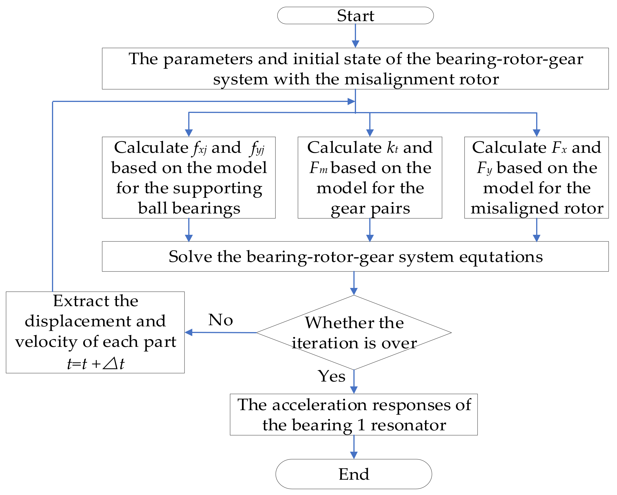
2. Dynamic Model for the Bearing-Rotor-Gear System with the Misaligned Rotor

In order to avoid the extreme complexity of the model, some reasonable simplifications are made: the rotor is rigid, the axial movement of the transmission system is ignored, and the misalignment defect is realized by the offset connection of the coupling.

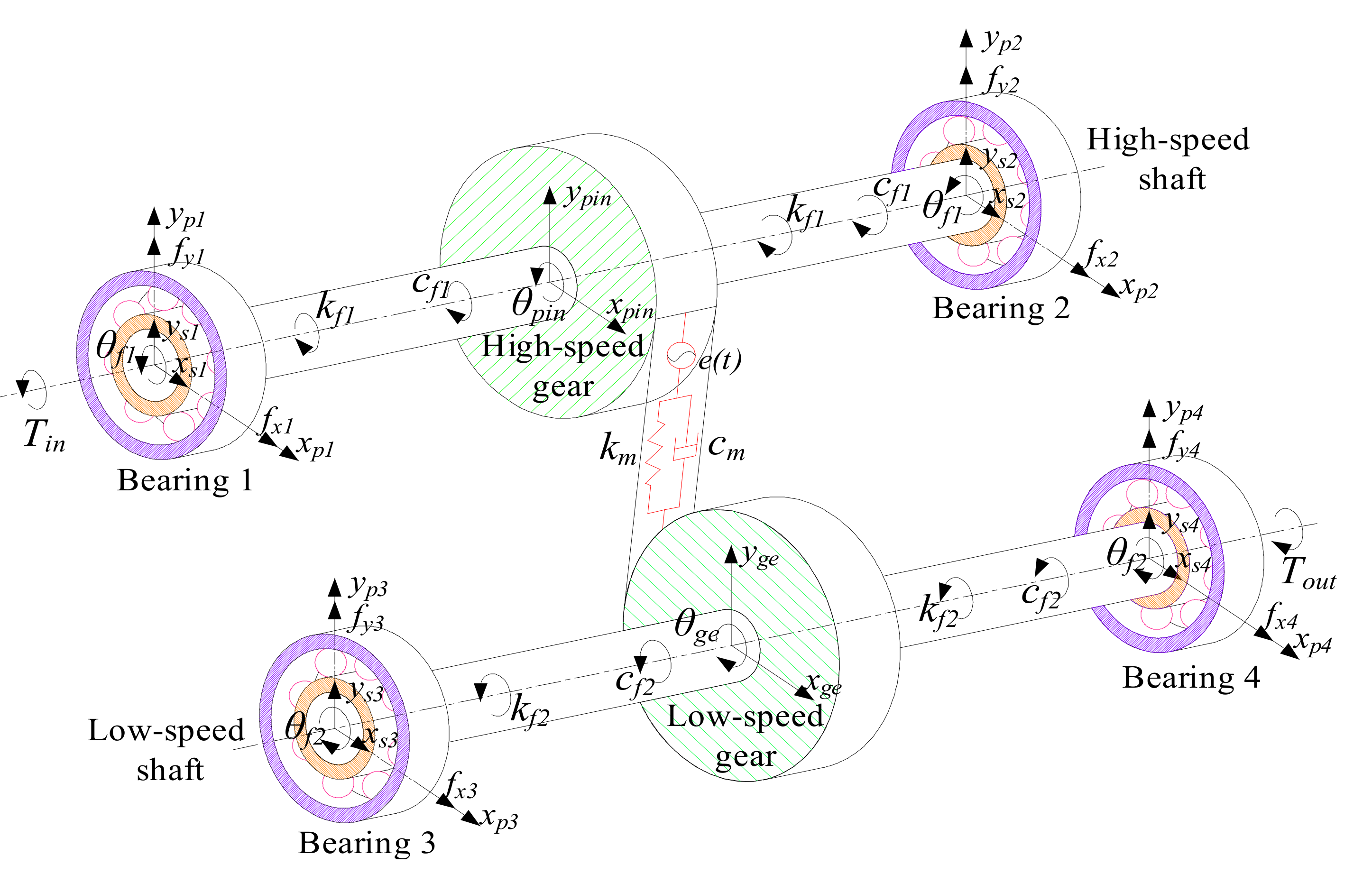
2.1. Dynamic Model for the Bearing-Rotor-Gear System

According to the Lagrange energy equations, a model is given for the bearing-rotor-gear system, which is shown in Figure 1. The corresponding system equations are [22]:
{ I f 1 θ ¨ f 1 + c f 1 θ ˙ f 1 θ ˙ p i n + k f 1 θ f 1 θ p i n = T i n m s 1 x ¨ s 1 + c s x 1 x ˙ s 1 x ˙ p i n + k s x 1 x s 1 x p i n + f x 1 + F x = 0 m s 1 y ¨ s 1 + c s y 1 y ˙ s 1 y ˙ p i n + k s y 1 y s 1 y p i n + f y 1 + F y = 0 m p 1 x ¨ p 1 + c p x 1 x ˙ p 1 + k p x 1 x p 1 f x 1 = 0 m p 1 y ¨ p 1 + c p y 1 + c r 1 y ˙ p 1 + k p y 1 + k r 1 y p 1 k r 1 y r 1 c r 1 y ˙ r 1 f y 1 = 0 m r 1 y ¨ r 1 + c r 1 y ˙ r 1 y ˙ p 1 + k r 1 y r 1 y p 1 = 0 I p i n θ ¨ p i n c f 1 θ ˙ f 1 θ ˙ p i n k f 1 θ f 1 θ p i n = R p i n F M m p i n x ¨ p i n + c s x 1 x ˙ p i n x ˙ s 1 + c s x 2 x ˙ p i n x ˙ s 2 + k s x 1 x p i n x s 1 + k s x 2 x p i n x s 2 = 0 m p i n y ¨ p i n + c s y 1 y ˙ p i n y ˙ s 1 + c s y 2 y ˙ p i n y ˙ s 2 + k s y 1 y p i n y s 1 + k s y 2 y p i n y s 2 = F M m s 2 x ¨ s 2 + c s x 2 x ˙ s 2 x ˙ p i n + k s x 2 x s 2 x p i n + f x 2 = 0 m s 2 y ¨ s 2 + c s y 2 y ˙ s 2 y ˙ p i n + k s y 2 y s 2 y p i n + f y 2 = 0 m p 2 x ¨ p 2 + c p x 2 x ˙ p 2 + k p x 2 x s 2 f x 2 = 0 m p 2 y ¨ p 2 + c p y 2 + c r 2 y ˙ p 2 + k p y 2 + k r 2 y p 2 k r 2 y r 2 c r 2 y ˙ r 2 f y 2 = 0 m r 2 y ¨ r 2 + c r 2 y ˙ r 2 y ˙ p 2 + k r 2 y r 2 y p 2 = 0 m s 3 x ¨ s 3 + c s x 3 x ˙ s 3 x ˙ g e + k s x 3 x s 3 x g e + f x 3 = 0 m s 3 y ¨ s 3 + c s y 3 y ˙ s 3 y ˙ g e + k s y 3 y s 3 y g e + f y 3 = 0 m p 3 x ¨ p 3 + c p x 3 x ˙ p 3 + k p x 3 x s 3 f x 3 = 0 m p 3 y ¨ p 3 + c p y 3 + c r 3 y ˙ p 3 + k p y 3 + k r 3 y p 3 k r 3 y r 3 c r 3 y ˙ r 3 f y 3 = 0 m r 3 y ¨ r 3 + c r 3 y ˙ r 3 y ˙ p 3 + k r 3 y r 3 y p 3 = 0 I g e θ ¨ g e c f 2 θ ˙ f 2 θ ˙ g e k f 2 θ f 2 θ g e = R g e F M m g e x ¨ g e + c s x 3 x ˙ g e x ˙ s 3 + c s x 4 x ˙ g e x ˙ s 4 + k s x 3 x g e x s 3 + k s x 4 x g e x s 4 = 0 m g e y ¨ g e + c s y 3 y ˙ g e y ˙ s 3 + c s y 4 y ˙ g e y ˙ s 4 + k s y 3 y g e y s 3 + k s y 4 y g e y s 4 = 0 m s 4 x ¨ s 4 + c s x 4 x ˙ s 4 x ˙ g e + k s x 4 x s 4 x g e + f x 4 = 0 m s 4 y ¨ s 4 + c s y 4 y ˙ s 4 y ˙ g e + k s y 4 y s 4 y g e + f y 4 = 0 m p 4 x ¨ p 4 + c p x 4 x ˙ p 4 + k p x 4 x p 4 f x 4 = 0 m p 4 y ¨ p 4 + c p y 4 + c r 4 y ˙ p 4 + k p y 4 + k r 4 y p 4 k r 4 y r 4 c r 4 y ˙ r 4 f y 4 = 0 m r 4 y ¨ r 4 + c r 4 y ˙ r 4 y ˙ p 4 + k r 4 y r 4 y p 4 = 0 I f 2 θ ¨ f 2 + c f 2 θ ˙ f 2 θ ˙ g e + k f 2 θ f 2 θ g e = T o u t
where If1, If2, Ipin, and Ige are the inertia moment of input rotor, output rotor, driving gear, and driven gear; θf1, θf2, θpin, and θge are the relative rotation angles; mpj, msj, and mrj are the mass of outer ring, inner ring, and resonator in the supporting bearings, j = 1,2,3,4; mpin and mge represent the driving and driven gear, kpxj, kpyj, ksxj, ksyj, and kryj are the stiffness of outer ring, inner ring, and resonator; cpxj, cpyj, csxj, csyj, and cryj are the relative damping; xpj, xsj, xpin, and xge are the displacement of the outer ring, inner ring, driving gear, and driven gear in the x direction; ypj, ysj, ypin, yge, and yrj are the displacement in the y direction; Rpin and Rge are the base radius of driving and driven gear; Tin and Tout are motor torque and load torque; fxj and fyj are contact forces in the supporting bearings; Fx and Fy are the excitation forces generated by the misaligned rotor; FM is the meshing force for the gear pairs.

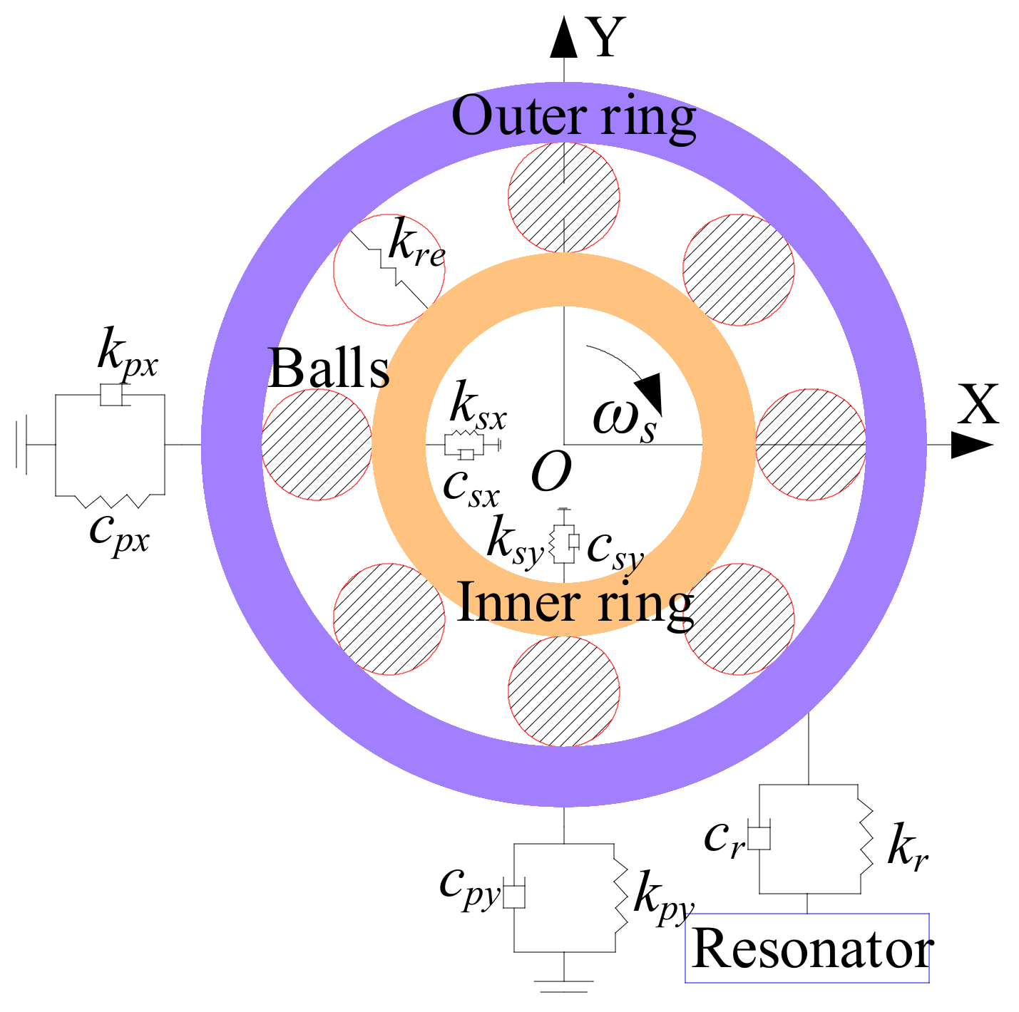
2.2. Model for the Supporting Ball Bearings

In order to obtain contact forces in the supporting bearings, the model for the supporting ball bearings is developed. As shown in Figure 2, the interaction between the outer ring and resonator in the bearing is simplified as a spring-damping system in the y direction, which is similar to the acceleration sensor for obtaining the acceleration signal of the system. Contact forces are calculated based on the Hertz method, and viscous force is ignored. Bearing 1 is an example, and the relative forces can be given as [23]:
f x 1 = k r e 1 i = 1 n b γ i ε i n cos θ i f y 1 = k r e 1 i = 1 n b γ i ε i n sin θ i
where: nb is the number of balls; kre1 and cre1 are the equivalent stiffness and damping coefficient between the ball and raceway; the value of n is 1.5; i is the serial number of balls. θi is the azimuth angle of ith ball and can be simulated by:
θ i = 2 π i 1 n b + 1 d b d m w s 2 t + θ 0
In the above equation, db is the ball diameter; dm denotes the bearing pitch diameter; θ0 represents the initial angle of the ith ball; ws and εi represent angular speed and contact deformation between the ring and the ball, and the expression is:
ε i = y s y p sin θ i + x s x p cos θ i c b w
where cbw is the bearing clearance, and γi is given as:
γ i = 1 δ i > 0 0 else        

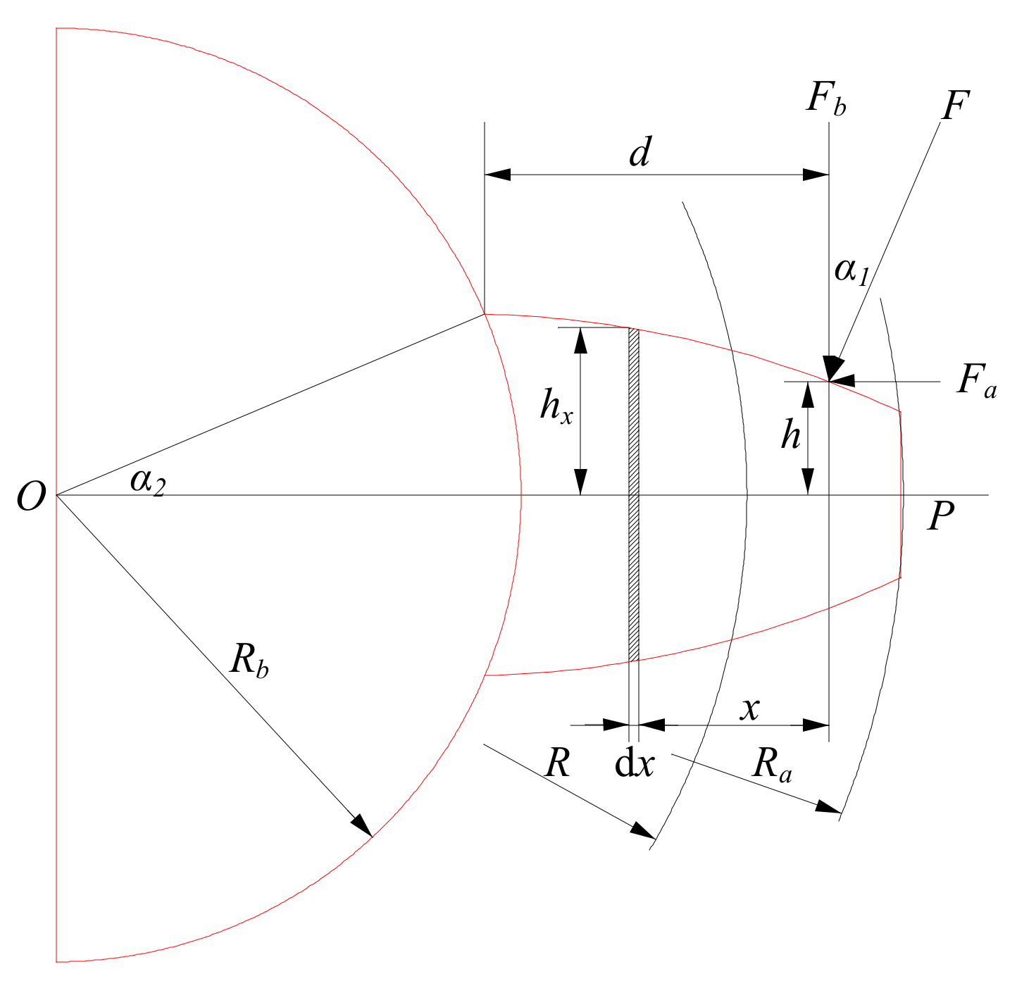
2.3. Model for the Gear Pairs

The meshing force FM between the gear pairs includes the viscous force Fc and elastic force Fk, and the relative expressions can be given as:
F M = F k + F c F k = k t R p i n θ p i n R g e θ g e y p i n + y g e e t F c = c t R p i n θ ˙ p i n R g e θ ˙ g e y ˙ p i n + y ˙ g e e ˙ t  
where ct is the meshing damping, kt is the meshing stiffness [24], which is:
1 k t = i = 1 2 1 k b 1 , i + 1 k s 1 , i + 1 k a 1 , i + 1 k h , i + 1 k f 1 , i + 1 k s 2 , i + 1 k f 2 , i + 1 k a 2 , i + 1 k b 2 , i double       tooth 1 k s 1 + 1 k b 1 + 1 k a 1 + 1 k h + 1 k f 1 + 1 k h + 1 k f 2 + 1 k b 2 + 1 k a 2 + 1 k h + 1 k s 2 sin gle       tooth
where kb, ks, kh, kf, and ka denote bending stiffness, contact stiffness, radial stiffness, deformation potential stiffness, and shear stiffness; 1 is for the driving gear, and 2 is for the driven gear. The calculation methods for the above stiffness are based on the cantilever beam model, which can be seen in Figure 3. In this figure, α1 is the actual meshing angle, α2 is half of the tooth angle. F is the meshing force, which can be decomposed into Fa and Fb. hx is the distance between any point on the tooth profile and OP, h is the distance between the actual meshing point and OP. Rb, R, and Ra are the base radius, the pitch radius, and the tip radius. dx is the integral element, x is the distance between dx and the actual meshing point, and d is the upper limit of the integral, which means the radial distance between the actual meshing point and the base circle. More details have been listed in the works of [25,26,27].
et is the transmission error, which is simulated by trigonometric functions [28]:
e t = e o + e m sin 2 π f m t + φ o
where em and eo represent the fluctuation and average error, φo is the initial phase, fm is the meshing frequency, and the relative calculation equation is listed in Appendix A.

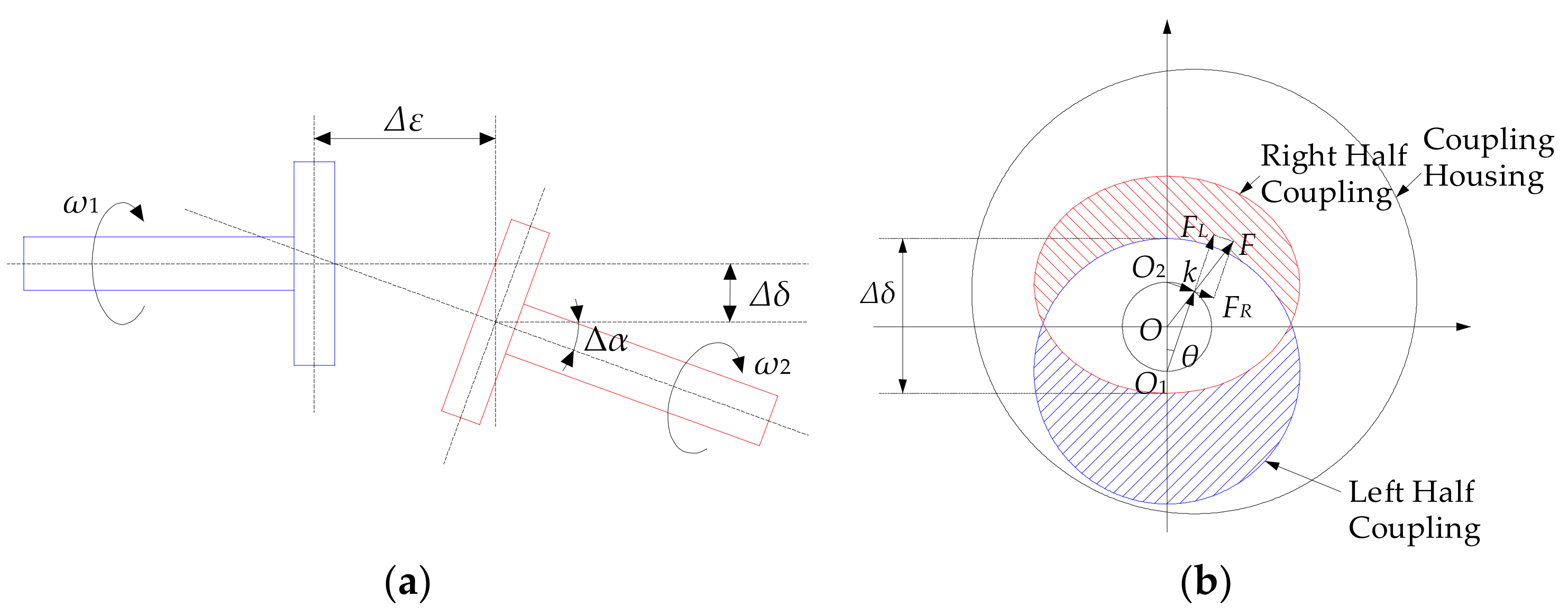
2.4. Model for the Misaligned Rotor
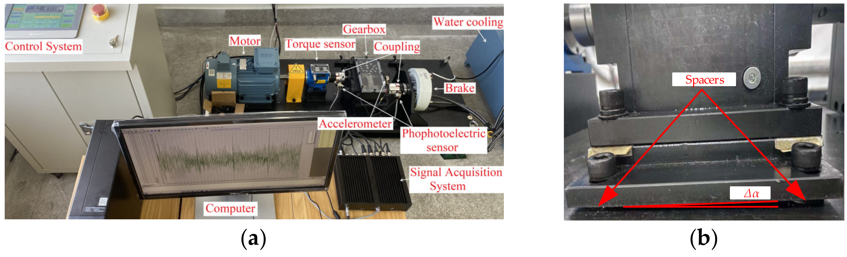
The excitation forces Fx and Fy are generated by the misaligned rotor, and a relative model is constructed. As shown in Figure 4a, the misaligned rotor is modeled by the offset connection of the coupling between the motor output rotor and the gearbox input rotor, ∆δ represents parallel misalignment, ∆α represents angular misalignment, and ∆ε is the distance from the left to the right in the coupling. The comprehensive misalignment ∆L of the rotor is expressed as [29]:
Δ L = Δ δ + Δ ε tan Δ α
In Figure 4b, the coordinate system is established, O is the static center of coupling housing, the dynamic center k of the coupling housing is (x,y), and the input angular velocity of the bearing-rotor-gear system is ω. The angular velocity of the coupling housing is also dθ/dt = ω. According to the geometric relationships, the dynamic center k can be obtained as:
x = Δ L sin θ cos θ = 1 2 Δ δ + Δ ε tan Δ α sin 2 θ y = Δ L cos θ cos θ 1 2 Δ L = 1 2 Δ δ + Δ ε tan Δ α cos 2 θ
Then, the following equation can be obtained:
2 x t 2 = 2 ω 2 Δ δ + Δ ε tan Δ α sin 2 θ 2 y t 2 = 2 ω 2 Δ δ + Δ ε tan Δ α cos 2 θ
Thus, the acceleration of the dynamic center k of the coupling is:
α k = 2 x t 2 2 + 2 y t 2 2 = 2 ω 2 Δ δ + Δ ε tan Δ α
The exciting forces generated by the coupling are FL and FR, respectively, and the resultant force is F, which can also be further decomposed as [30,31]:
F x = F sin 2 ω t = m c α k sin 2 ω t = 2 m c ω 2 Δ δ + Δ ε tan Δ α sin 2 ω t F y = F cos 2 ω t = m c α k cos 2 ω t = 2 m c ω 2 Δ δ + Δ ε tan Δ α cos 2 ω t
where mc is the mass of the coupling housing.

3. Results

The Runge–Kutta method is selected for solving the gear-rotor-bearing system equations. The acceleration response in the vertical axis of the resonator in bearing 1 is given, which can be used to discuss the vibration characteristic of the system. In order to highlight the frequency components, the acceleration response is in the process of the logarithm, and the corresponding unit is also changed from the original m/s2 to dB. The bearing types and defect frequencies are selected in Table 1, and the relative calculation equations are listed in Appendix A. The parameters for the bearing-rotor-gear system are shown in Table 2 and Table 3. The calculation process can be seen in Figure 5.
For verifying the theoretical model, the relative experiment is performed. The test bench of the bearing-rotor-gear system is shown in Figure 6a. The defective rotor can be seen in Figure 6b, the misalignment defect is realized by adding spacers to the fixing bolts of the gearbox, and the offset connection between the motor output rotor and the gearbox input rotor can be controlled by the number of spacers. The transmission ratio of gear pairs is 23:81, and the supporting bearing types are 6308 and 6304, which are manufactured in the NSK Ltd, Tokyo, Japan. The speed of the motor is set as 1800 rpm, and the load torque is 30 Nm. The acceleration sensor is used for measuring the vibration signal, and the sampling frequency is 30 kHz. The measuring point is on the bearing housing, which is the closest to the misaligned coupling. Moreover, the acceleration responses in the vertical direction are sampled. Finally, the measured time-domain signal is processed by using a four-layer wavelet transform [32], and the high-frequency signal of each layer is filtered, then the low-frequency signal in the fourth layer is reconstructed to achieve low-pass filtering and noise reduction.
After the experiment is performed, the acceleration responses are measured, and the comparison between the experiment and simulation can be seen in Figure 7. As shown in Figure 7a, when the rotor system is misaligned, the time-domain responses for the bearing-rotor-gear system are modulated by the rotor frequency fr1, the time-domain response fluctuates up and down, and the interval between adjacent shocks is the rotor frequency fr1. The frequency-domain response for the gearbox is given in Figure 7b. There are rotor frequency fr1 and harmonic frequencies, such as fo1 ± fr1, fm ± fr1. Through the comparison, it is found that frequency components obtained by the experiment are far more than the simulation result. This is mainly because there are some simplifications in this theoretical model; the uncertain excitations in the experiment can rarely be considered. However, the frequency components obtained by the calculation method can all be found in the experiment result. Thus, the theoretical model is verified.

4. Discussion

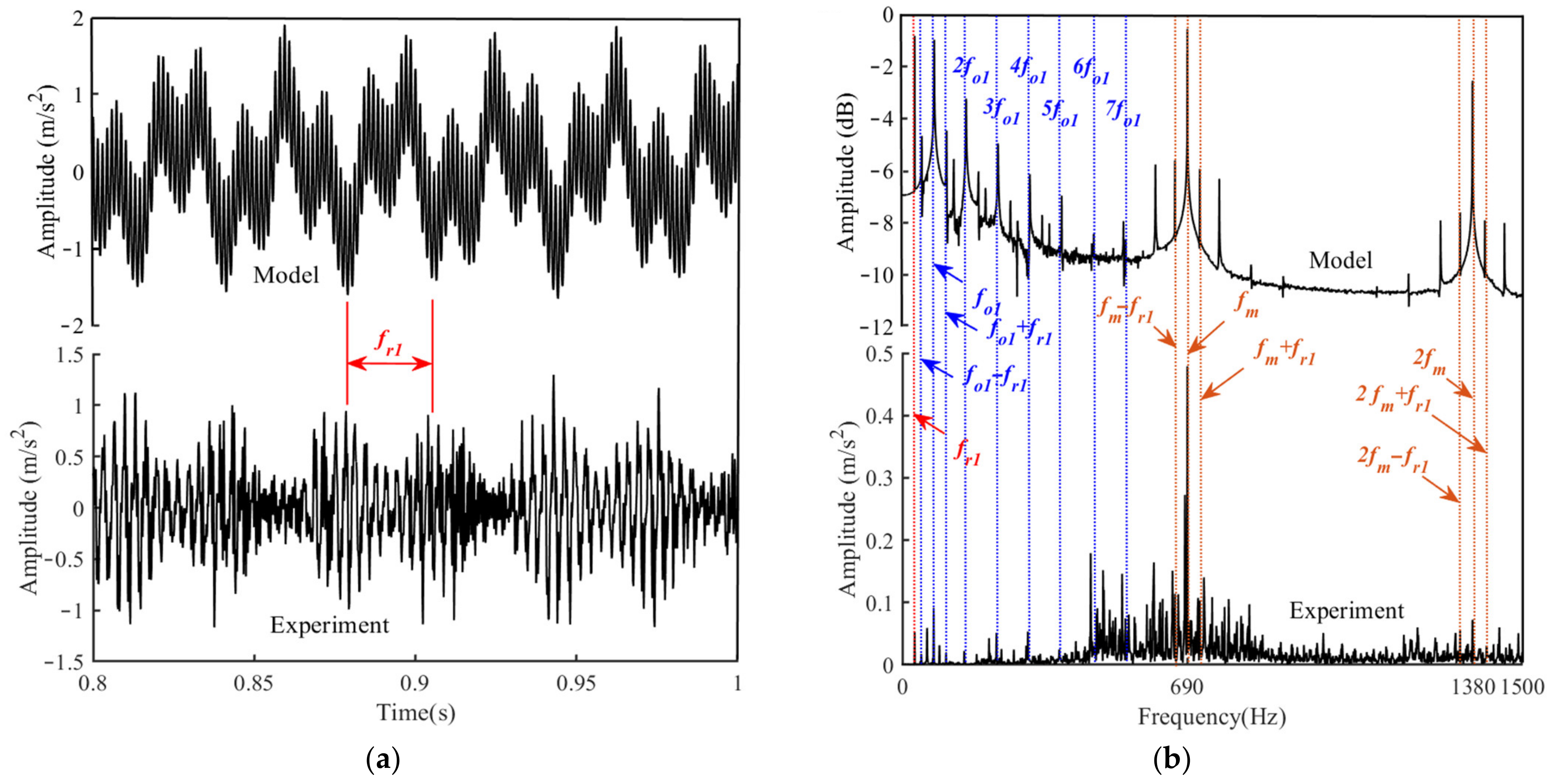
4.1. Vibration Response for the Bearing-Rotor-Gear System with the Misaligned Rotor

Based on the built model, vibration responses of the bearing-rotor-gear system with the misaligned rotor are investigated. The results are given in Figure 8. As shown in Figure 8a, acceleration responses of the healthy bearing-rotor-gear system are relatively stable, and time-domain response is slightly modulated by defect frequency fo1. When the rotor is misaligned, there are obvious fluctuations on the response curve, which is modulated by the rotor frequency fr1. With the increase in the comprehensive misalignment ∆L, the fluctuation trend increases, and the amplitude modulation of fr1 on the response curve is enhanced. Figure 8b shows the frequency-domain response of the bearing-rotor-gear system. It is found that the spectrum of the healthy system is mainly composed of outer raceway frequency in the bearings and meshing frequency between the gear pairs, such as fo1, 2fo1, 3fo1, 4fo1, fm, and 2fm. When there is a misalignment rotor, the rotor frequency and the relative harmonic frequencies can also be found, such as fr1, fo1 ± fr1, fo1 ± 2fr1, and fm ± fr1. These harmonic frequencies are mainly excited by the misalignment rotor, and the harmonic frequencies for the bearing are extremely sensitive. As the misalignment defect deepens, the frequency components of the spectrum become more complex, and there are high-order harmonic frequencies, such as 2fo1 ± fr1, 3fo1 ± fr1, fm ± 2fr1, 2fm ± fr1, and 2fm ± 2fr1. This indicates that higher-order harmonic responses are excited with the deepening misalignment defect.
In order to discuss the vibration characteristic of the bearing-rotor-gear system with the misaligned rotor, some indicators are given, which are shown in Figure 9. The root mean square (RMS) and peak-to-peak (xp-p) in the statistics method are used to process the acceleration responses, which are listed in Figure 6a. When the comprehensive misalignment of the rotor magnifies from ∆L = 0 to ∆L = 0.2 + 0.2 × tan(1°)mm, xp-p, and RMS are consistently increasing, the vibration generated by the system becomes more severe. The amplitudes of the rotor frequency fr1, defect frequency fo1, and meshing frequency fm are extracted, and the relative results are plotted in Figure 6b–d. It is found that the amplitude of fr1 magnifies continuously with the aggravation of the defect degree, and the amplitude modulation effect is enhanced. In addition, the amplitude of fo1 and the harmonic frequency fo1 + fr1 is also increasing, which means that the fundamental frequency and harmonic responses of the bearing are enhanced, and the support and modulation effect of the bearing is also strengthened. The change in the amplitude of fm is almost imperceptible, and the amplitude of fm ± fr1 is increasing. The fundamental frequency response for the gear pairs is almost unaffected. However, the relative harmonic response is enhanced.

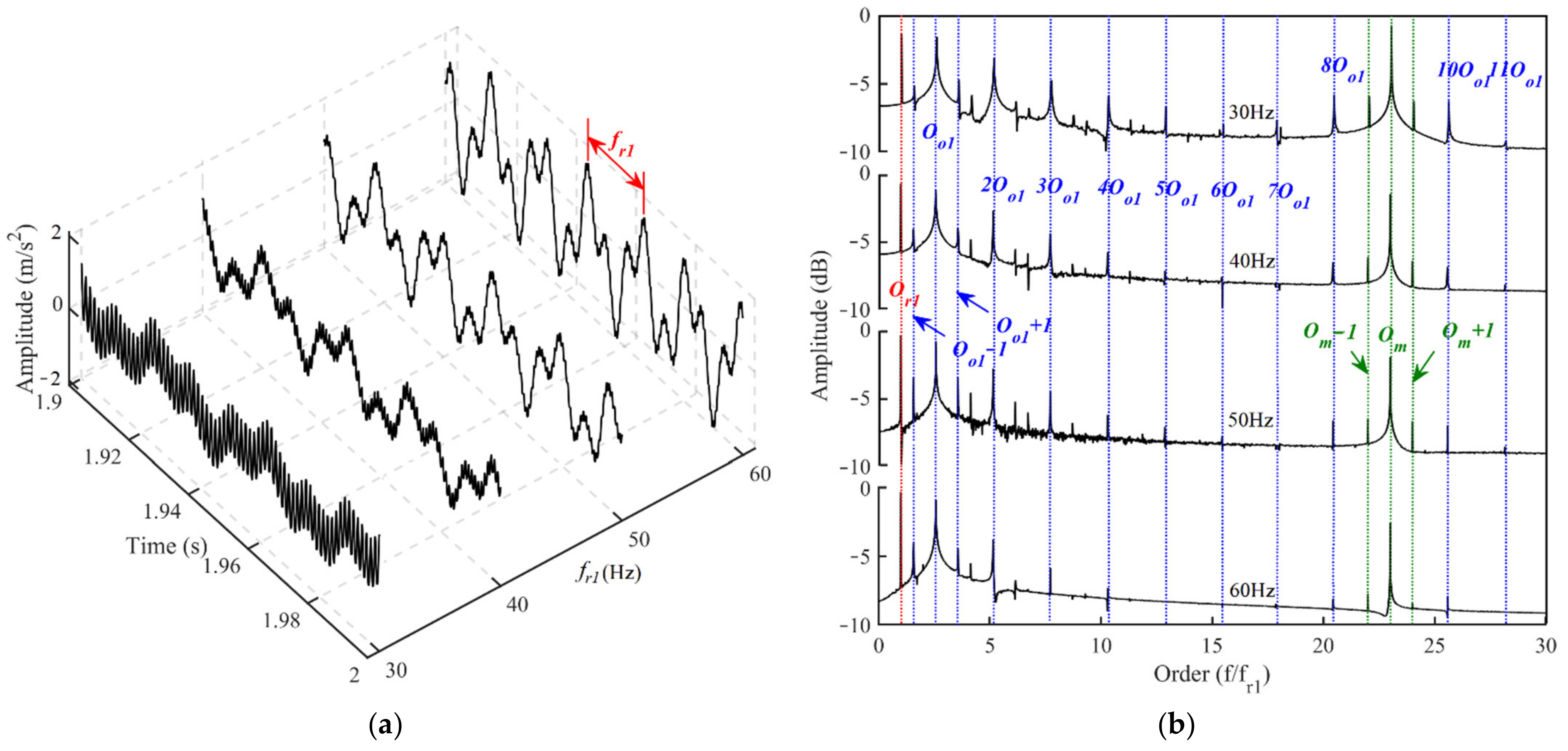
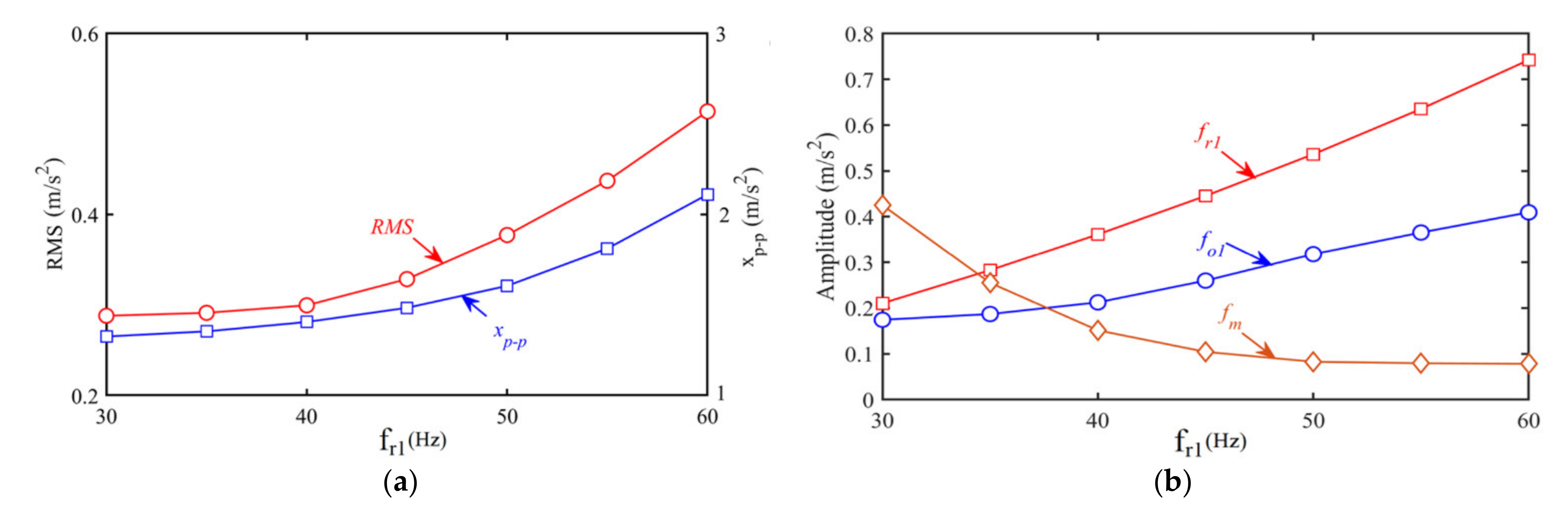
4.2. Influence of Speed on Vibration Responses for the Bearing-Rotor-Gear System

When the input speed is increasing, vibration characters of the bearing-rotor-gear system may become more obvious. Thus, for discussing the influence of speed on vibration responses of the bearing-rotor-gear system with a misaligned rotor, the comprehensive misalignment is set to ∆L = 0.1 + 0.1 × tan (1°) mm, the input speed is set as rotor frequency fr1, the relative results are given in Figure 10. As seen in Figure 10a, when the input speed is raised, the fluctuation of the time-domain response is more severe, and the amplitude modulation effect of the rotor frequency fr1 and the defect frequency fo1 is enhanced. The interval between adjacent shocks is the rotor frequency fr1, so the modulation effect of the rotor frequency is more obvious. In order to facilitate the comparison of the frequency-domain response, the order analysis method in the work of [33] is used to discuss the frequency composition of the spectrum at different speeds, as shown in Figure 10b. The frequency order Or1 of the input rotor is defined as 1, then the fundamental order of the bearing outer raceway is Oo1 = 0.5nbfr1(1 − dbdm)⁄fr1 = 2.57, and the fundamental order of the gear pairs is Om = z1fr1fr1 = 23. When the input speed is raised, the composition of the order spectrum is similar. There are still Or1, Oo1, and Om, as well as the harmonic order, such as Oo1 ± 1 and Om ± 1. However, the higher-order frequency is difficult to find, and the harmonic orders are mainly distributed in the low-frequency band, which shows that the super-harmonic response and high-order harmonic response of bearings and gear pairs can be blocked so that the bearing and gear pair mainly vibrate at the fundamental frequency or low-frequency band.
The same method is used to quantify vibration responses at different speeds, which is shown in Figure 11. The amplitudes of xp-p and RMS magnify with the increasement of the input speed. On the contrary, the amplitude of fm is reduced, which means the vibration of the gear pairs is no longer the main source of system vibration. The fundamental frequency response of the gear pairs is weakened due to the misalignment defect, and the vibration of the transmission system is mainly caused by the misalignment defect and the supporting action of the bearing.

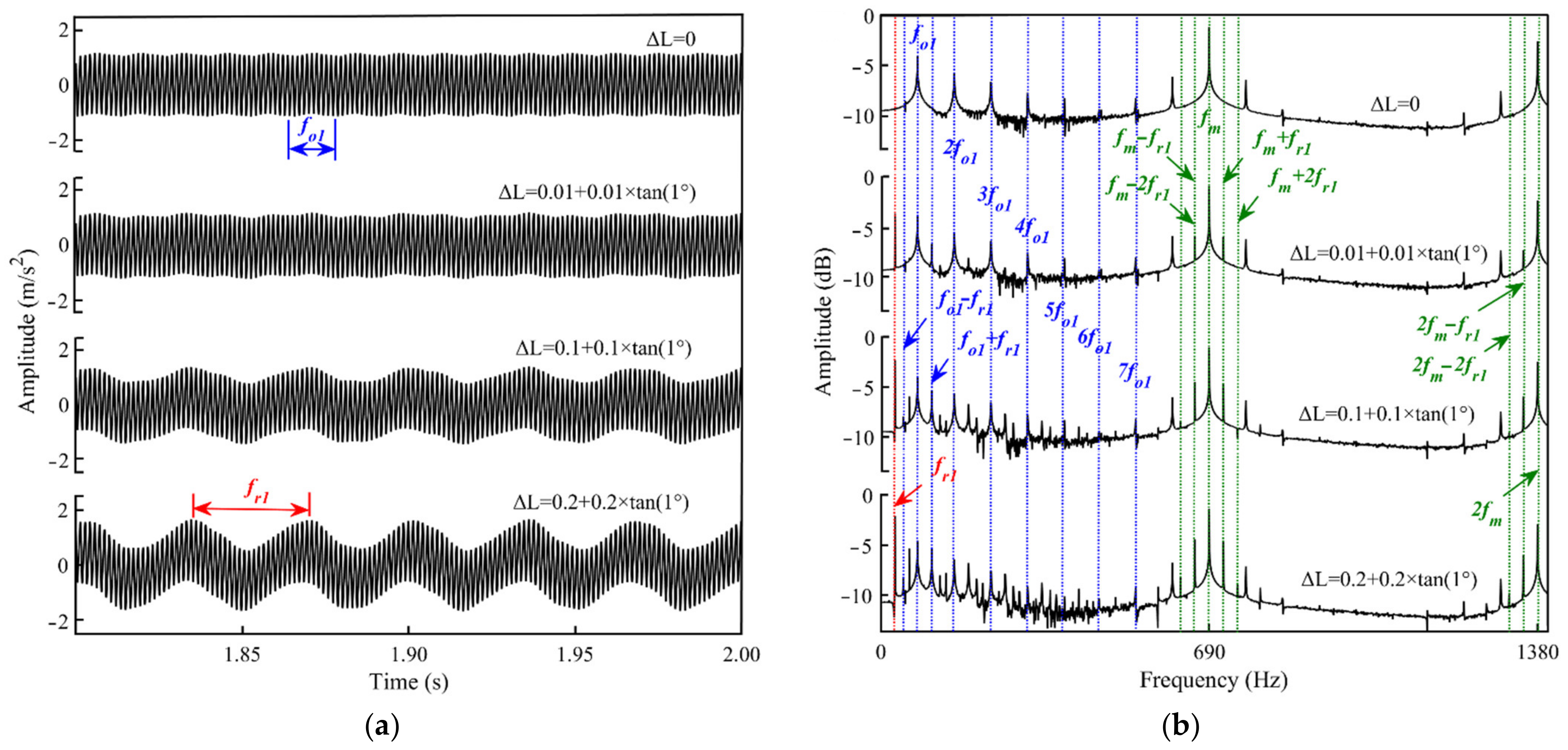
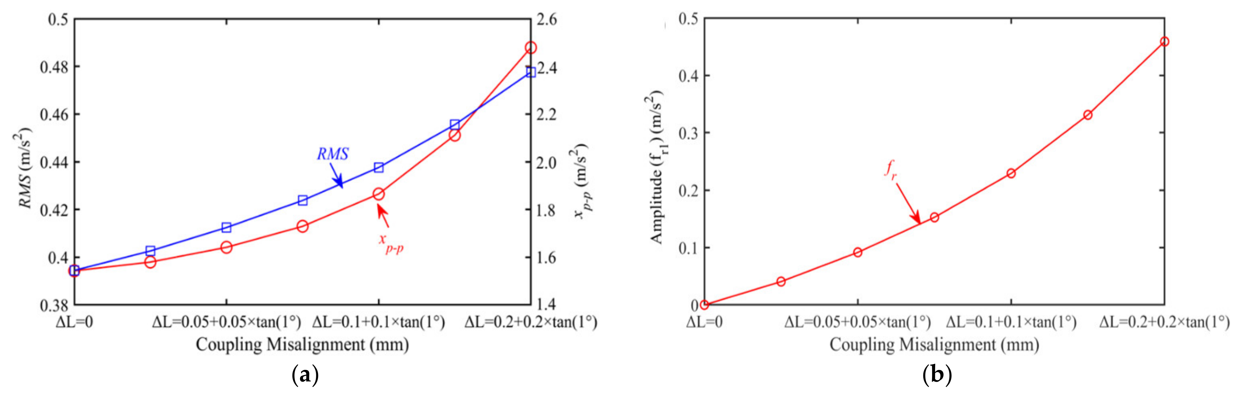
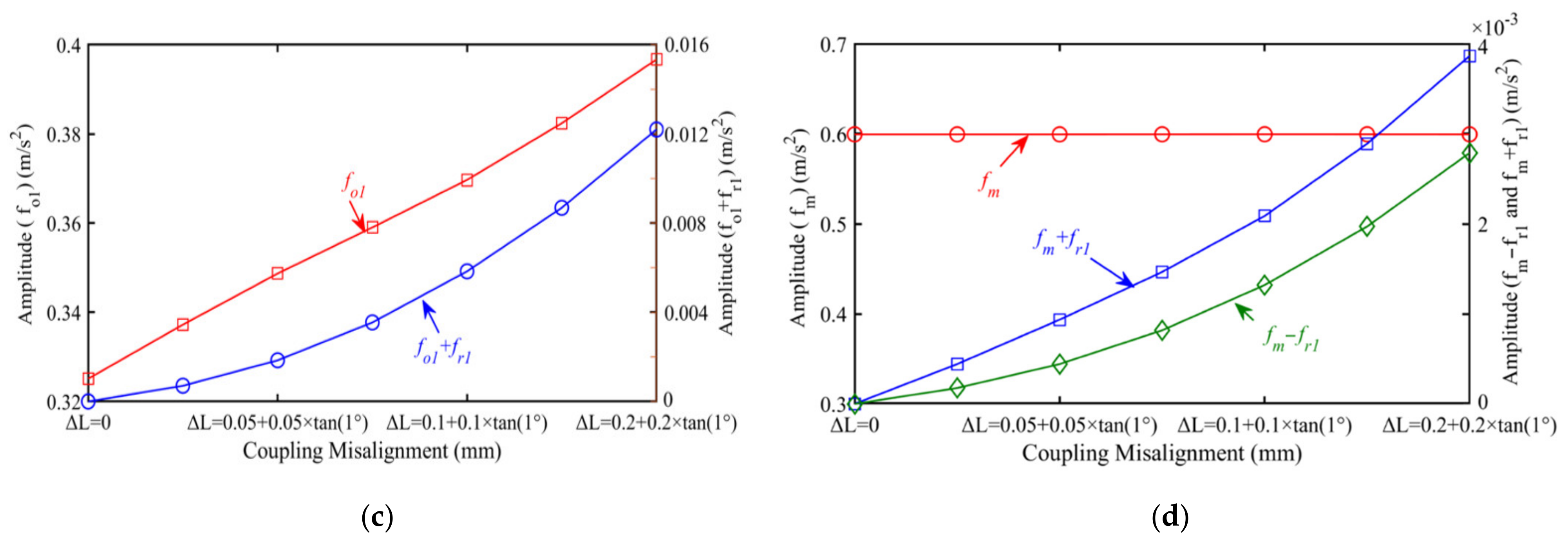
4.3. Influence of Load on Vibration Responses of the Bearing-Rotor-Gear System

When the bearing-rotor-gear system with the rotor misalignment defect is operated under different loads, the comprehensive misalignment is set to ∆L = 0.1 + 0.1 × tan (1°) mm, and the input rotational frequency fr1 is 30 Hz. The relative results are shown in Figure 12. It can be seen that the acceleration responses are little affected by the load, and the response curves under different loads are similar. As the load increases, only the amplitude of the response is in enlargement. The spectrum composition under different loads is also extremely similar, such as fr1, fo1, fo1 ± fr1, fm, and fm ± fr1, and there are no other new frequency components in the spectrum.
The amplitudes of the frequencies are extracted in Figure 13. When the load increases, the amplitudes of fr1, defect frequency fo1, and meshing frequency fm are also enlarged, which indicates the vibration caused by the bearings and the gear pairs is intensified, and the amplitude modulation of fr1 is also enhanced. The amplitudes of the harmonic frequencies fo1 ± fr1 and fm ± fr1 are both increasing, and the harmonic response is also enhanced.

5. Conclusions

In order to realize vibration responses of the bearing-rotor-gear system with the misaligned rotor, a mathematical model is established. The bearings and the gear pairs are stitched by the misalignment rotor. The misalignment defect is realized by the offset connection of the coupling, and the excitation forces are transferred to the bearing inner ring through the rigid rotor. The established model is verified by the experiment. The main conclusions are summarized as follows:
(1)
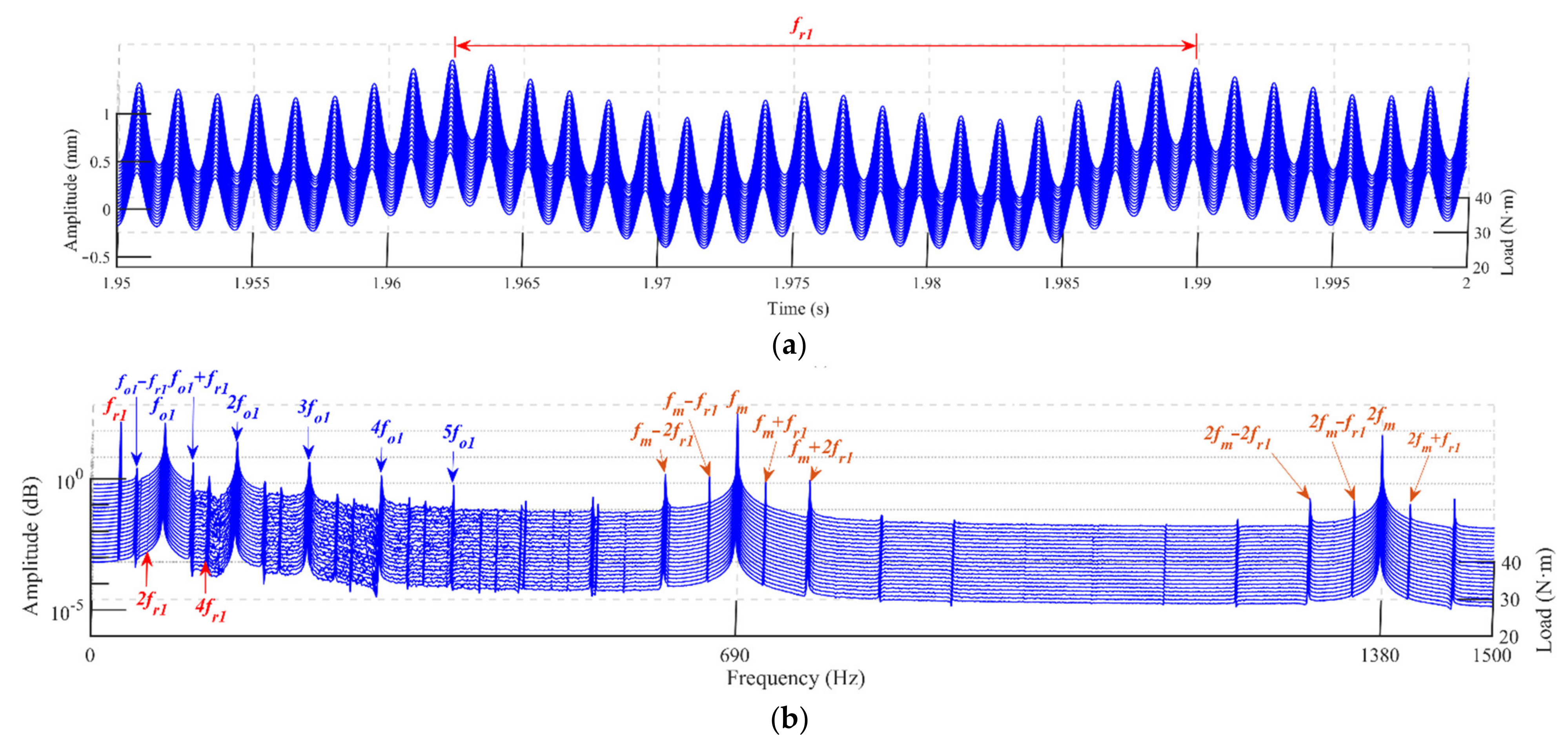
When there are misalignment defects on the rotor, the vibration responses of the system are modulated by rotor frequencies, and there are rotor frequencies in the spectrum. Harmonic responses of gear pairs and the bearing outer raceways are excited. As the misalignment defect deepens, the high-order harmonic responses increase.
(2)
The modulation caused by the rotor misalignment defect is accentuated. When the input speed is raised, the vibration caused by the gear pairs is attenuated, the harmonic response and super-harmonic response of the bearings can be suppressed, and the system vibrates mainly at the fundamental frequency.
(3)
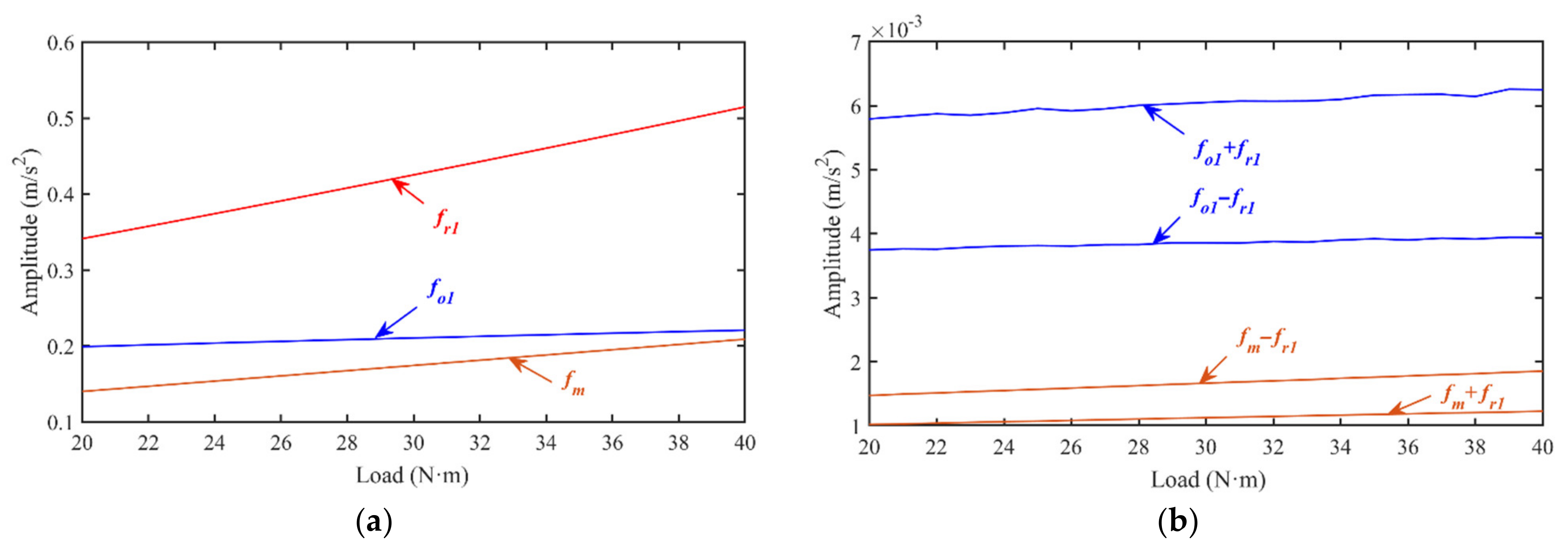
When the load is increasing, the amplitude of the rotor frequency, meshing frequency, and defect frequency of the bearing outer raceway are all enlarged.

Author Contributions

Conceptualization, F.W.; methodology, F.W.; software, F.W.; validation, F.W.; formal analysis, P.D.; investigation, P.D.; resources, P.D. and J.W.; data curation, P.D.; writing—original draft preparation, P.D.; writing—review and editing, L.N. and J.W.; visualization, P.D.; supervision, J.W.; project administration, L.N. All authors have read and agreed to the published version of the manuscript.

Funding

The work described in this paper was supported by the National Natural Science Foundation of China (no. 51905001) and the Science and Technology of Wuhu (no. 2021yf09).

Institutional Review Board Statement

Not applicable.

Informed Consent Statement

Not applicable.

Data Availability Statement

Not applicable.

Conflicts of Interest

There are no personal circumstances or interest that may be perceived as inappropriately influencing the representation or interpretation of reported research results in this paper.

Appendix A

The defect frequencies are calculated by the following equations [33,34]:
(1)
Rotor frequency
f r = w s 60
(2)
Bearing outer ring frequency
f o = f r 2 n b 1 d b d m
(3)
Bearing inner ring frequency
f i = f r 2 n b 1 + d b d m
(4)
Meshing frequency for the gear pairs
f m = z 1 f r

References

  1. Zhou, S.; Song, G.; Ren, Z.; Wen, B. Nonlinear dynamic analysis of coupled bearing-rotor-gear system with the effect of internal and external excitations. Chin. J. Mech. Eng. 2015, 29, 281–292. [Google Scholar] [CrossRef]
  2. Song, C.; Bai, H.; Zhu, C.; Wang, Y.; Feng, Z.; Wang, Y. Computational investigation of off-sized bearing rollers on dynamics for hypoid gear-shaft-bearing coupled system. Mech. Mach. Theory 2021, 156, 104177. [Google Scholar] [CrossRef]
  3. Xiao, H.; Zhou, X.; Liu, J.; Shao, Y. Vibration transmission and energy dissipation through the gear-shaft-bearing-housing system subjected to impulse force on gear. Measurement 2017, 102, 64–79. [Google Scholar] [CrossRef]
  4. Zhang, Y.; Fang, B.; Kong, L.; Li, Y. Effect of the ring misalignment on the service characteristics of ball bearing and rotor system. Mech. Mach. Theory 2020, 151, 103889. [Google Scholar] [CrossRef]
  5. Tuckmantel, F.W.; Cavalca, K.L. Vibration signatures of a rotor-coupling-bearing system under angular misalignment. Mech. Mach. Theory 2019, 133, 559–583. [Google Scholar] [CrossRef]
  6. Jalan, A.K.; Mohanty, A.R. Model based fault diagnosis of a rotor-bearing system for misalignment and unbalance under steady-state condition. J. Sound Vib. 2009, 327, 604–622. [Google Scholar] [CrossRef]
  7. Jiang, H.; Shao, Y.; Mechefske, C.K. Dynamic characteristics of helical gears under sliding friction with spalling defect. Eng. Fail. Anal. 2014, 39, 92–107. [Google Scholar] [CrossRef]
  8. Wen, C.; Meng, X.; Fang, C.; Gu, J.; Xiao, L.; Jiang, S. Dynamic behaviors of angular contact ball bearing with a localized surface defect considering the influence of cage and oil lubrication. Mech. Mach. Theory 2021, 162, 104352. [Google Scholar] [CrossRef]
  9. Dhamande, L.S.; Chaudhari, M.B. Compound gear-bearing fault feature extraction using statistical features based on time-frequency method. Measurement 2018, 125, 63–77. [Google Scholar] [CrossRef]
  10. Dal, A.; Karaçay, T. Effects of angular misalignment on the performance of rotor-bearing systems supported by externally pressurized air bearing. Tribol. Int. 2017, 111, 276–288. [Google Scholar] [CrossRef]
  11. Xu, M.; Marangoni, R. Vibration analysis of a motor-flexible coupling-rotor system subject to misalignment and unbalance, Part I: Theoretical model and analysis. J. Sound Vib. 1994, 176, 663–679. [Google Scholar] [CrossRef]
  12. Xu, M.; Marangoni, R. Vibration analysis of a motor-flexible coupling-rotor system subject to misalignment and unbalance, Part Ⅱ: Experiment validation. J. Sound Vib. 1994, 176, 681–691. [Google Scholar] [CrossRef]
  13. Marmol, R.A.; Smalley, A.J.; Tecza, J.A. Spline Coupling Induced Nonsynchronous Rotor Vibrations. J. Mech. Des. 1980, 102, 293–303. [Google Scholar] [CrossRef]
  14. Lee, Y.S.; Lee, C.W. Modeling and vibration analysis of misaligned rotor-ball bearing systems. J. Sound Vib. 1999, 224, 17–32. [Google Scholar] [CrossRef]
  15. Al-Hussain, K.M. Dynamic stability of two rigid rotors connected by a flexible coupling with angular misalignment. J. Sound Vib. 2003, 266, 217–234. [Google Scholar] [CrossRef]
  16. DeSmidt, H.; Wang, K.; Smith, E. Coupled torsion-lateral stability of a shaft-disk system driven through a universal joint. J. Appl. Mech. 2002, 69, 261–273. [Google Scholar] [CrossRef]
  17. A1-Hussain, K.; Redmond, I. Dynamic response of two rotors connected by rigid mechanical coupling with parallel misalignment. J. Sound Vib. 2002, 249, 483–498. [Google Scholar] [CrossRef]
  18. Dewell, D.; Mitchell, L. Detection of a misaligned disk coupling using spectrum analysis. J. Vib. Acoust. 1984, 106, 9–16. [Google Scholar] [CrossRef]
  19. Sekhar, A.S.; Prabhu, B.S. Effects of coupling misalignment on vibrations of rotating machinery. J. Sound Vib. 1995, 185, 655–671. [Google Scholar] [CrossRef]
  20. Lees, A.W. Misalignment in rigidly coupled rotors. J. Sound Vib. 2007, 305, 261–271. [Google Scholar] [CrossRef]
  21. Pennacchi, P.; Vania, A.; Chatterton, S. Nonlinear effects caused by coupling misalignment in rotors equipped with journal bearings. Mech. Syst. Signal Process 2012, 30, 306–322. [Google Scholar] [CrossRef] [Green Version]
  22. Sawalhi, N.; Randall, R.B. Simulating gear and bearing interactions in the presence of faults. Mech. Syst. Signal Process 2008, 22, 1924–1951. [Google Scholar] [CrossRef]
  23. Wang, F.T.; Jing, M.Q.; Yi, J.; Dong, G.; Liu, H.; Ji, B. Dynamic modelling for vibration analysis of a cylindrical roller bearing due to localized defects on raceways. Proc. Inst. Mech. Eng. Part K J. Multi-Body Dyn. 2015, 229, 39–64. [Google Scholar] [CrossRef] [Green Version]
  24. Ma, R.; Chen, Y.; Cao, Q. Research on dynamics and fault mechanism of spur gear pair with spalling defect. J. Sound Vib. 2012, 331, 2097–2109. [Google Scholar] [CrossRef]
  25. Jia, S.X.; Howard, I. Comparison of localized spalling and crack damage from dynamic modeling of spur gear vibrations. Mech. Syst. Signal Process 2006, 20, 332–349. [Google Scholar] [CrossRef]
  26. Chen, Z.; Ji, P. Research on the variation of mesh stiffness and transmission error for spur gear with tooth profile modification and wear fault. Eng. Fail. Anal. 2021, 122, 105184. [Google Scholar] [CrossRef]
  27. Dai, H.; Long, X.; Chen, F.; Xun, C. An improved analytical model for gear mesh stiffness calculation. Mech. Mach. Theory 2021, 159, 104262. [Google Scholar] [CrossRef]
  28. Ma, R.; Chen, Y. Research on the dynamic mechanism of the gear system with local crack and spalling failure. Eng. Fail. Anal. 2012, 26, 12–20. [Google Scholar] [CrossRef]
  29. Inayat-Hussain, J.I. Nonlinear dynamics of a statically misaligned flexible rotor in active magnetic bearings. Commun. Nonlinear Sci. Numer. Simul. 2010, 15, 764–777. [Google Scholar] [CrossRef]
  30. Wu, K.; Liu, Z.; Ding, Q. Vibration responses of rotating elastic coupling with dynamic spatial misalignment. Mech. Mach. Theory 2020, 151, 103916. [Google Scholar] [CrossRef]
  31. Prabhakar, S.; Sekhar, A.S.; Mohanty, A.R. Crack versus coupling misalignment in a transient rotor system. J. Sound Vib. 2003, 266, 773–786. [Google Scholar] [CrossRef]
  32. Long, L.; Wen, X.; Lin, Y. Denoising of seismic signals based on empirical mode decomposition-wavelet thresholding. J. Vib. Control 2021, 27, 311–322. [Google Scholar] [CrossRef]
  33. Harris, T.A. Advanced Concepts of Bearing Technology, 1st ed.; John Wiley & Sons, Inc.: New York, NY, USA, 2006. [Google Scholar]
  34. Dai, P.; Wang, J.; Yan, S.; Huang, S.; Wang, F.; Liu, J. Vibration characteristics of the gear shaft-bearing system with compound defects under variable operating conditions. Proc. Inst. Mech. Eng. Part K J. Multi-Body Dyn. 2022, 236, 113–129. [Google Scholar] [CrossRef]
Figure 1. Dynamic model of the bearing-rotor-gear system.
Machines 10 00267 g001
Figure 2. Model of the supporting ball bearing.
Machines 10 00267 g002
Figure 3. Cantilever beam model.
Machines 10 00267 g003
Figure 4. The model for the misalignment rotor: (a) the misaligned rotor; (b) exciting forces.
Machines 10 00267 g004
Figure 5. The flow chart of the calculation process.
Machines 10 00267 g005
Figure 6. Experimental equipment: (a) the bearing-rotor-gear system test bench; (b) the rotor misalignment defect.
Machines 10 00267 g006
Figure 7. The comparison between experiment and simulation: (a) time-domain response; (b) frequency-domain response.
Machines 10 00267 g007
Figure 8. Vibration characters of the bearing-rotor-gear system with the misaligned rotor: (a) acceleration response; (b) frequency spectrum.
Machines 10 00267 g008
Figure 9. Indicators for vibration characteristics of the bearing-rotor-gear system with the misaligned rotor: (a) RMS and xp-p; (b) amplitudes of fr1; (c) amplitudes of fo1 and fo1 + fr1; (d) amplitudes of fm and fm ± fr1.
Machines 10 00267 g009aMachines 10 00267 g009b
Figure 10. Influence of speed on vibration characters of the bearing-rotor-gear system: (a) acceleration response; (b) frequency spectrum.
Machines 10 00267 g010
Figure 11. Indicators for vibration characteristics of the bearing-rotor-gear system at different speeds: (a) RMS and xp-p; (b) amplitudes of fr1, fo1, and fm.
Machines 10 00267 g011
Figure 12. Influence of load on vibration characters of the bearing-rotor-gear system: (a) acceleration responses; (b) frequency spectrum.
Machines 10 00267 g012
Figure 13. Indicators for vibration characteristics of the bearing-rotor-gear system at different loads: (a) amplitudes of fr1, fo1, and fm; (b) amplitudes of fo1 ± fr1 and fm ± fr1.
Machines 10 00267 g013
Table 1. Bearing types and defect frequencies.
BearingsTypesDefect Frequency of
Inner Raceway fi/Hz
Defect Frequency of Outer Raceway fo/Hz
Bearing 16304132.7981.13
Bearing 26304132.7981.13
Bearing 3630837.7121.92
Bearing 4630837.7121.92
Table 2. Main parameters of the gear pairs.
ParametersDriving GearDriven Gear
Pressure angle α/(°)2020
Modulus m/mm22
Number of teeth z2381
Young’s modulus E/GPa216216
Tooth width W/mm2424
Table 3. Parameters of the bearing-rotor-gear system model.
ParametersValue
Inertia moment of input rotor If1/(kg⋅m2)0.0021
Inertia moment of driving gear Ipin/(kg⋅m2)4.365 × 10−4
Inertia moment of driven gear Ige/(kg⋅m2)8.362 × 10−4
Inertia moment of output rotor If2/(kg⋅m2)0.0105
Load Tout(N/m)30
Average transmission error eo/m3.0 × 10−5
Transmission fluctuation range em/m2.0 × 10−5
Torsional stiffness of rotor kf1, kf2/(Nm/rad)4.4 × 105
Torsional damping of rotor cf1, cf2/(Nms/rad)5.0 × 105
Support stiffness in the bearings ksj, kpj, krj/(N/m) 6.7 × 10⁷
Support damping in the bearings csj, cpj, crj/(Ns/m)1.8 × 105
Mass of coupling housing mc/kg1
Mass of driving gear mpin/kg0.96
Mass of driven gear mge/kg2.88
Rotation frequency of input rotor fr1/Hz30
Meshing frequency fm/Hz690
Publisher’s Note: MDPI stays neutral with regard to jurisdictional claims in published maps and institutional affiliations.

