1. Introduction
In the traction gear transmission of high-speed EMUs, the gears undergo elastic deformation due to the contact stress, which causes the gear base circle pitch to change, causing the gears to interfere at the critical point of meshing and meshing. At the same time, due to factors such as gear matching errors, the gears cause dynamic loads or shock during transmission. The impact of biting in and out will cause vibration and noise in the gear meshing process, which affects the comfort of passengers and endangers the safe driving of the train. Therefore, it is necessary to study further the stability of traction gear transmission and vibration and noise reduction technology. Gear modification is a universal step-up transmission performance, reduces vibration and noise, and improves passenger comfort. It is an efficient path to optimize gear modification using the simulation method of finite element analysis, constructing the optimization model of gear modification parameters, and settling by the optimization algorithm. Gao et al. optimized the design of a specific marine gear shift and improved the hydraulic oil supply system. The experimental results indicate that the gear modification and improved hydraulic oil supply system can effectively improve the vibration performance of the gearbox [
1]. Zhang et al. chose a sensible modification plan to modify the small sun gear of an electric vehicle gearbox. Comparing the simulation results indicates that proper modification can reduce the gear transmission vibration and noise [
2]. Liu et al. made a micro-modification of the gear, after which the trans-mission error of the gear pair was reduced by about 30%, and the contact stress was significantly reduced [
3]. Xu et al. studied the star gear system, and the conclusions proved that the gear modification could improve the gear transmission condition [
4]. Dorofeev et al. optimized the tooth profile modification parameters to reduce the gear transmission error [
5]. Han et al. proposed an energy method combined with a genetic algorithm to modify the optimization plan. Gears optimized by this method have a suitable damping effect [
6]. Tang et al. combined BP neural network and genetic algorithm to explore gear modification and finally obtained the optimal vibration effect modification parameter combination [
7]. MA et al. used Romax to build the three-dimensional model of gear reducer and optimized gear micro-geometric modification method using a genetic algorithm. Finally, verified the gear modification effect [
8]. Liu et al. used the NSGA-II to optimize the gear modification amount based on the minimum load-bearing transmission error amplitude [
9]. Kalinin analyzed the dynamic characteristics of gears under different modification parameters and proved the necessity of changing the calculation method of tooth profile modification parameters [
10]. Zhou et al. used Romax software to establish a reliable dual-clutch transmission gear system model. We sampled a combination of gear comprehensive modification parameters and the use of a genetic algorithm for optimization [
11]. Zhang et al. studied a particular type of planetary gear and solved the modification amount of gear by combining genetic algorithms [
12]. Yang et al. applied the Kriging model and genetic algorithm to gear modification and achieved satisfactory results [
13].
Most of the above studies have established mathematical models for measuring the noise intensity by gear transmission error amplitude, dynamic meshing force fluctuation, tooth surface stress distribution, acceleration, Etc., ignoring the system’s acoustic response field effect is impossible to perform ideally and accurately. A small number of scholars started to study the modification and optimization to reduce the radiated noise of the gear transmission. Timm et al. conducted a force analysis and structural finite element simulation on the automobile mechanical transmission pump casing and obtained the position of the pump with the high load. Results of the vibroacoustic model were compared with the sound pressure level of the pump measured in a semi-anechoic chamber [
14]. Zhang used gear modification as an optimization method to complete the radiation noise analysis of a medium-duty truck manual transmission case through the direct boundary element method. Tang et al. used the acoustic boundary element method to solve the radiated noise of EMU gears and predicted the radiated noise [
15]. The research conclusions have guiding significance for the study on noise reduction of EMU gears [
16]. Hua et al. used Kisssoft combined with Virtual. Lab software to design the gear shape and noise reduction. Calculations indicate that the gear shape modification dramatically reduces the sound power level of the gearbox [
17]. Wang used the acoustic boundary element method to solve the noise distribution cloud map of the bevel gearbox under specific working conditions, and the research results provided theoretical support for gear vibration and noise reduction [
18]. Tang et al. used RBF neural network to build a predictive model of radiated noise from EMU gear transmission. The optimization model of modification parameters is constructed, then the multi-island genetic algorithm is taken to solve the model to obtain the minimum noise [
19]. To solve the gear noise problem, Phi. CH et al. [
20] used a mathematical model to estimate the impact on the sound pressure level. Based on the establishment of gearbox modal parameters, the technical progress of gear angular vibration analysis and the influence of self-excited vibration on gear noise are described.
Most of the above studies used the acoustic boundary element method to study the gear transmission noise as a basis for noise reduction. However, they did not combine the intelligent algorithm to optimize the parameters of the modification. The reason is that it is difficult to define the effective law of gear structural parameters on noise, and configured mathematical relationship model more complicated, involving intermediate multibody dynamics, a plurality of field mode theory, acoustics, is the difficulty interdisciplinary. Moreover, more parameters relate to gear modification, and each parameter will affect the other, which makes the coupling difficult. In view of the above series of difficulties, this paper adopts Romax software which integrates modeling, shape modification and dynamic simulation functions, and firstly establishes a parameterized model of EMU gear transmission system. Then, according to the theory of gear modification, a comprehensive modification method combining tooth orientation and tooth profile is determined. The dynamic simulation analysis of gear system is carried out, and the corresponding vibration response characteristics are obtained. Combined with radiation noise theory, acoustic boundary element method (BEM) was used to solve the radiation noise of gear system casing, and then a complete simulation process from dynamics to acoustics was established, and the noise data under different modification parameters was obtained. The prediction model of modification parameters-radiation noise was built by GRNN, and the optimization model of modification parameters aiming at minimizing the radiated noise was solved by PSO algorithm. Finally, the optimal combination data of modification parameters was obtained, and the effectiveness of the results was verified by experimental simulation.
2. Parametric Design of Traction Gear Transmission System
Taking a certain EMU traction gear transmission system as the research object, the parametric modeling is carried out by using Romax software. Then select the appropriate modification plan, calculate the modification parameter amount, determine the reasonable sampling method, and prepare for the follow-up work.
2.1. Construction of the Traction Gear Transmission Parameterized Model
According to the parameters of the traction gear transmission system of the EMU (summarized in
Table 1), Romax software is used to structure the simulation model. The three-dimensional model established is described in
Figure 1.
2.2. Selection of Modification Scheme
Axial modification is the corresponding modification of the tooth surface in the tooth direction. It can achieve the purpose of improving the gear surface load distribution and increasing the gear carrying capacity. At the same time, the vibration and impact of gear during meshing can be reduced to prolong the service life of the gear. Generally, drum shape modification is the primary method of axial modification. The general methods of tooth profile modification are top and root trimming. The purpose is to optimize the dynamic performance of gear transmission, effectively reduce the transmission error, and make the gear system more stable and reliable.
Through analysis and a combination of related theories, combining tooth axial with tooth profile modification is adopted. Under the premise to ensure the modification effect, combining traditional and actual work experience, the gear modification is carried out only for the drive gear, pinion.
2.3. Calculation of Modification Parameters and Determination of Sampling Scheme
Tooth profile modification value is not only affected by the elastic deformation of the gear teeth when loaded but also related to the deviation of the base section during manufacturing, expressed as the formula:
Here: is the amount of tooth profile modification (µm); is the amount of elastic deformation when the gear is loaded (µm); is the machining base pitch error (µm).
Refer to GB/Z6413.1-2003 to obtain the elastic deformation of the gear as:
Here: is the gear service coefficient under working conditions; represents the branching coefficient; means the tooth width (mm); represents the end face pressure angle (); represents the tangential force (N); represents the meshing stiffness (N/(mm·µm)). Let us take 1 for both and .
The tangential force of the gear drive can be expressed as follows:
In Formula (3): means the tangential force (N); is the diameter of the gear index circle (mm); is the nominal torque (N·m).
Factual data can be found in the Romax software, torque N·m; indexing circle diameter mm; end face pressure angle ; meshing stiffness N/(mm·µm); machining base pitch error µm. It can be calculated that the maximum value of the pinion tooth profile modification amount is 11.60 µm.
Determine the amount of drum repair tooth modification is a crucial step. It has a significant influence on the later modification effect.
According to the calculation method of drum shape modification in ISO 6336-1 standard, the method is the use of Formulas (4) and (5) of the drum, and the modification formula is incorporated by reference experience:
Here: is the toothed drum modification amount (µm); means the tooth width (mm); represents the tooth direction error determined by the accuracy (µm); represents the coefficient determined by the accuracy level, and the value is 2.0 under the 6th level of accuracy.
The calculation shows that the maximum amount of drum shape of the pinion gear is 17 µm.
Based on the calculated gear modification parameters, the amount of drum modification, inclination, and profile modification of the pinion is determined by combining the sampling data. The data range setting is as illustrated in
Table 2.
3. Dynamics and Noise Simulation Analysis of Traction Gear Transmission System
The dynamics simulation analysis of the gear transmission system model is carried out, including unit load, analysis of transmission error, modal analysis, and bearing vibration acceleration analysis. The acoustic BEM is used to carry out an acoustic numerical simulation to solve the magnitude of its radiated noise. The results can be used for the following modification work and the comparative basis of the final modified effect. The specific parameters of high-speed conditions are as follows: motor output torque: 499.31 N·m; motor output speed: 6102 rpm; power: 320 kW. Material properties of gear pair are defined as shown in
Table 3. Material properties of gearbox are shown in
Table 4.
3.1. Analysis of Gear Unit Load
Unit load distribution is an important indicator to evaluate the quality of the shape modification and noise reduction. It can visually reflect the distribution of contact spots and can be used as a reference basis for the ultimate modification quality. Uniform load distribution is conducive to the stable operation of gear transmission.
The unit load of the gear is the average load P (N/mm) of the unit length along the tooth surface contact line, which can be represented as:
Here: indicates the average load acting on the tooth surface (N); means the length of the contact line along the tooth surface (mm).
Analyzing the related theories and combining Formula (6), the unit load analysis of the traction gear transmission of EMU is carried out with the aid of Romax software, and obtain the load distribution per unit length of the pinion and the wheel as shown in
Figure 2 and
Figure 3.
From the analysis of
Figure 2 and
Figure 3, it is observed that the contact spots formed in gear set under high-speed working conditions manifest that the left side of the gear set is subject to a more significant stress load, while the right tooth surface is subject to a smaller stress load. It shows a severe phenomenon of eccentric load in the meshing process of gear-pair, which makes it easier to produce meshing impact and vibration noise. The purpose of the uniform load should be achieved in the subsequent modification.
3.2. Transmission Error Analysis
Gear transmission error means the difference between the peak values of the transmission error curve, which has a more significant impact on the transmission noise during the operation of the gear transmission system. The theoretical expression is as follows:
Here: is the transmission error (µm); indicates the pitch circle radius of the driving wheel (µm); represents the radius of the driving wheel pitch circle (µm); means the theoretical transmission angle of the driving wheel (); represents the theoretical transmission angle of the driven wheel ().
Since the installation error and meshing impact cannot be avoided, the actual transmission angle of the driven wheel is:
Here: represents the actual transmission angle of the driven wheel (); is the angular deviation value caused by the transmission error ().
Using Romax software to analyze the transmission error of gear set, the curve of transmission error is shown in
Figure 4, and the corresponding data are integrated into
Table 5.
Analysis of the graph found gear set transmission error value 0.503 μm, subsequent modification to make the gear transmission error can be reduced, which can reduce noise.
3.3. Modal Analysis of Gearbox
Modal analysis of the EMU gearbox is equivalent to analyzing the gearbox’s natural frequency and modal vibration mode. The natural frequency refers to the frequency at which the gear pair meshes under specific working conditions. The mode shape is the state of the transmission system and the box under a specific mode when the gear pair is meshing or the rotating shaft is running. It radiates to the entire system, causing its shape to deform.
The dynamic equation of an undamped free vibration system can be obtained by Fourier transform:
Here: represents the mass matrix of the system; represents the stiffness matrix; represents the eigenvector which does not change with time; the eigenvalue represents the natural frequency.
The modal analysis is actually to study the vibration of the gearbox of the EMU under a certain modal. Based on the existing theory and practical experience, when the load vibrates the box, the resonance of the low-order mode has a worse impact on the box. Through the analysis of the modal theory, combined with the calculation formula, the Romax software is used to extract the first 10 modes of the gearbox, and the results are shown in
Table 6. Among them, the mode shape of the first mode is depicted in
Figure 5.
Combined with the analysis of modal data and mode shapes, it is helpful to understand the gearbox structure characteristics and avoid the gearbox’s resonant problem.
3.4. Analysis of Bearing Vibration Acceleration
Vibration response analysis is a crucial part of dynamics analysis, and it is also the core step of EMU gear transmission noise analysis. Therefore, the vibration response of the transmission gear under high-speed working conditions should be solved first, and then the noise response characteristics should be analyzed.
The forced vibration equation of an undamped system is as follows:
Here: represents the vibration displacement (mm); represents the vibration acceleration (); represents the system excitation load (N).
The excitation load of the harmonic response is as follows:
Here: represents the load amplitude (N); represents the natural vibration frequency of the system (Hz); represents the load phase angle ().
To analyze the vibration of the entire gear system, the targeted selection of five different locations of nodes. The specific location of the node in the gearbox is exhibited in
Figure 6. The frequency harmonic response amplitude curve of each node on the gear system is exhibited in
Figure 7.
Figure 7 shows the characteristics of each node of the system under the response frequency curve. The obtained results are saved in
file format, which can be used as the excitation conditions of the forced vibration response of the gearbox in the subsequent acoustic simulation analysis to obtain the surface vibration response data of the gearbox. It provides boundary conditions for boundary element analysis.
3.5. Numerical Analysis of Gear Transmission System Noise
The acoustic radiation is calculated by extracting the surface mesh of the gearbox structure through the Helmholtz boundary integral equation of the boundary element method (BEM). Described gear transmission vibration and noise radiation to the surrounding air, Helmholtz acoustic boundary element equations for the system can be represented by the following formula:
Here: means the sound pressure (); represents the sound transfer vector; is the corresponding frequency (); is the average velocity of the vibration of the surface unit of the structure ().
The sound pressure
and the average velocity
at any point in the gear transmission system radiated sound field from the sound source
satisfy:
Here: means the number of nodes on a cell ; represents the sound pressure at the node of the boundary element; represents the average velocity at the node of the element; represents the shape function of the element.
This article studies the noise radiation of the transmission gear system in the air and how to reduce the noise through gear modification. That is, to improve the noise source. Therefore, the sound power is selected as the acoustic quantity to measure the magnitude of the noise. At the same time, to facilitate comparison, the calculation result of the acoustic simulation uses the root mean square (RMS) value of the acoustic power level over the entire frequency.
Acoustic radiation is actually the transmission of acoustic energy, and the acoustic energy radiated by the sound source in unit time is called acoustic power. The average sound energy passing through a plane of area
perpendicular to the direction of sound wave diffusion in unit time is called the average sound power, which can be expressed as:
Here:
represents the velocity of sound;
represents the area in the direction of sound wave diffusion;
means the sound energy density, and its calculation formula is as follows:
Here:
is the original volume of the acoustic energy unit;
is the pressure of the medium at rest;
is the density of the medium. For the convenience of comparison, the sound power level is defined as follows:
Here: the reference sound power .
Import the finite element model of gear box into Virtual. Lab to define shell attributes, and detailed parameters are shown in
Table 3. Then the bearing vibration response excitation (
file) calculated in Romax is applied to the gear box in Virtual. Lab, the forced vibration response analysis of the shell is carried out, and the result is used as the acoustic boundary element condition. The vibration response data on the model volume grid obtained by the response analysis are transferred to the acoustic grid through data transfer, and then the vibration response of the acoustic grid can be excited. The finite element model of the gearbox and the obtained vibration response data is imported into the acoustic boundary element module of Virtual. Lab for acoustic simulation analysis to solve the noise level of the gear transmission system [
21].
Calculating cabinet noise radiation needs to define the properties of the sound field material and the field point grid. The sound field medium of this model is set to air, and the ISO standard spherical field is used. The basic parameter settings are as follows: the reference sound intensity is set to ; the reference sound pressure is set to ; the air density is set to 1.225 ; the sound speed is set to 340 .
Virtual. Lab uses the acoustic boundary element method to generate the ISO standard spherical sound field diagram, exhibited in
Figure 8. The point on the spherical sound field is 1 m away from the centre of the gear transmission system. The sound pressure level nephogram of the gear transmission radiated noise obtained is shown in
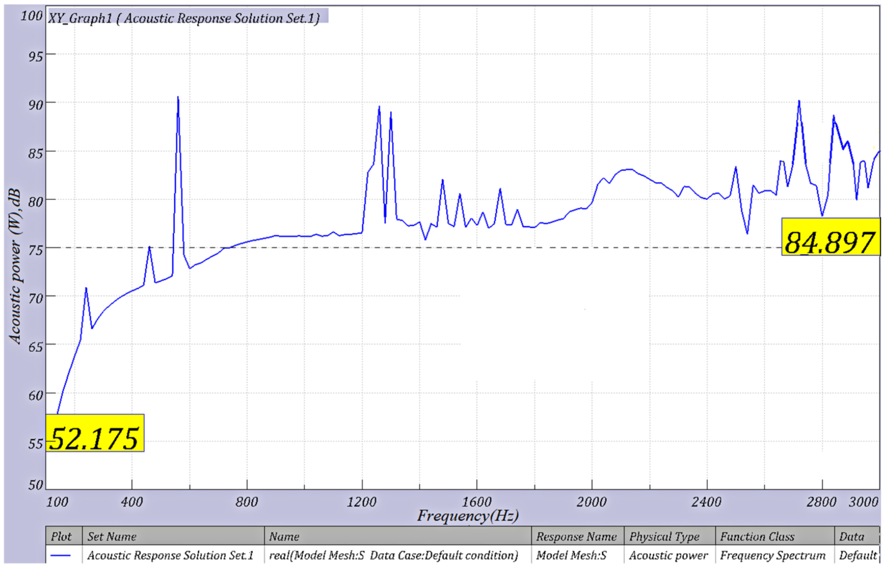
Figure 9. The acoustic pressure level cloud diagram, combined with the Formulas (15)–(17), the radiated noise acoustic power level curve and RMS of acoustic power level can be obtained, as shown in
Figure 10.
The acoustic power curve is shown in
Figure 10. Combined with the software, the RMS of the acoustic power level of the EMU gear transmission system radiated noise is 96.59 dB. According to the TSI 2008/232/CE regulations on noise limits, when the EMU is running at high speed (speed
300
), the noise outside the car should be
91 dB. Therefore, it is necessary to modify the gears of the EMU to reduce the transmission noise.
4. Noise Prediction Model of Traction Gear Transmission System Based on Generalized Regression Neural Network
The combination of modification parameters is extracted through the optimal Latin hypercube sampling design (OptLHD). The modification parameters were imported into Romax software in turn to establish the gear modification model, and the dynamic simulation analysis was carried out. Then, the acoustic boundary element module of Virtua. Lab software is used for acoustic simulation analysis of gear system casing, and radiation noise data corresponding to different modification parameters are obtained. Based on the obtained data, using generalized regression neural network (GRNN) to construct the required noise prediction model.
4.1. Data Sampling Based on Optimal Latin Hypercube
The OptLHD module in Isight software was used to sample the range of modification parameters in
Table 2, and 100 groups of modification parameter data were obtained.
Latin Hypercube Design (LHD)’s working principle is as follows: uniformly divide each coordinate space of n-dimensional space into m parts to form an n-dimensional space with m samples expressed as m × n LHD. Latin Hypercube performs well in terms of pace-filling ability and has a solid ability to fit nonlinear responses. However, its disadvantage is the uneven distribution of test points. OptLHD principle of the method with LHD similar, but the space such as a probability distribution, thus improving the problem of uneven LHD test points, improved fitting precision experiment factors. The sample data extracted by the OptLHD method are uniformly distributed, as shown in
Figure 11.
4.2. Constructing the Noise Prediction Model of Gear Transmission System
The 100 sets of modification parameter combinations obtained by sampling are imported into Romax software in turn to establish a gear modification model, and dynamic simulation analysis is carried out. Then use the Virtual. Lab software acoustic boundary module for acoustic analysis. Obtain multiple sets of data with modification parameters as input and radiation noise size as output.
Collecting noise data obtained by simulation, a correspondence relationship is formed with the noise parameter modification, as shown in
Table 7.
The 100 groups of gear modification parameters were sampled as the input data of the prediction model, and the corresponding radiated noise data were taken as the output data. Based on this, the noise prediction model of EMU traction gear transmission system is constructed. Generalized regression neural network (GRNN) to give the desired radiation noise prediction model.
GRNN is built by radial basis function neuron combined with linear neuron, which belongs to a radial basis function neural network. It often uses for function approximation. It has a good predictive ability for small sample data sets, and it also has enormous advantages in dealing with unstable data. Combining the analysis with the data samples of this study, GRNN was selected to construct a modification parameters-noise prediction model due to the small number of data samples.
Three modification parameters are selected as the input of the neural network model, and the radiated noise of the gear transmission system is used as the output. The radiated noise prediction model is constructed:
Here: is the RMS value (dB) of the acoustic power level corresponding to the scanning frequency band of the radiated noise; is the pinion tooth drum modification amount (µm); represents the amount of pinion tooth inclination (µm); represents the amount of pinion tooth profile modification (µm).
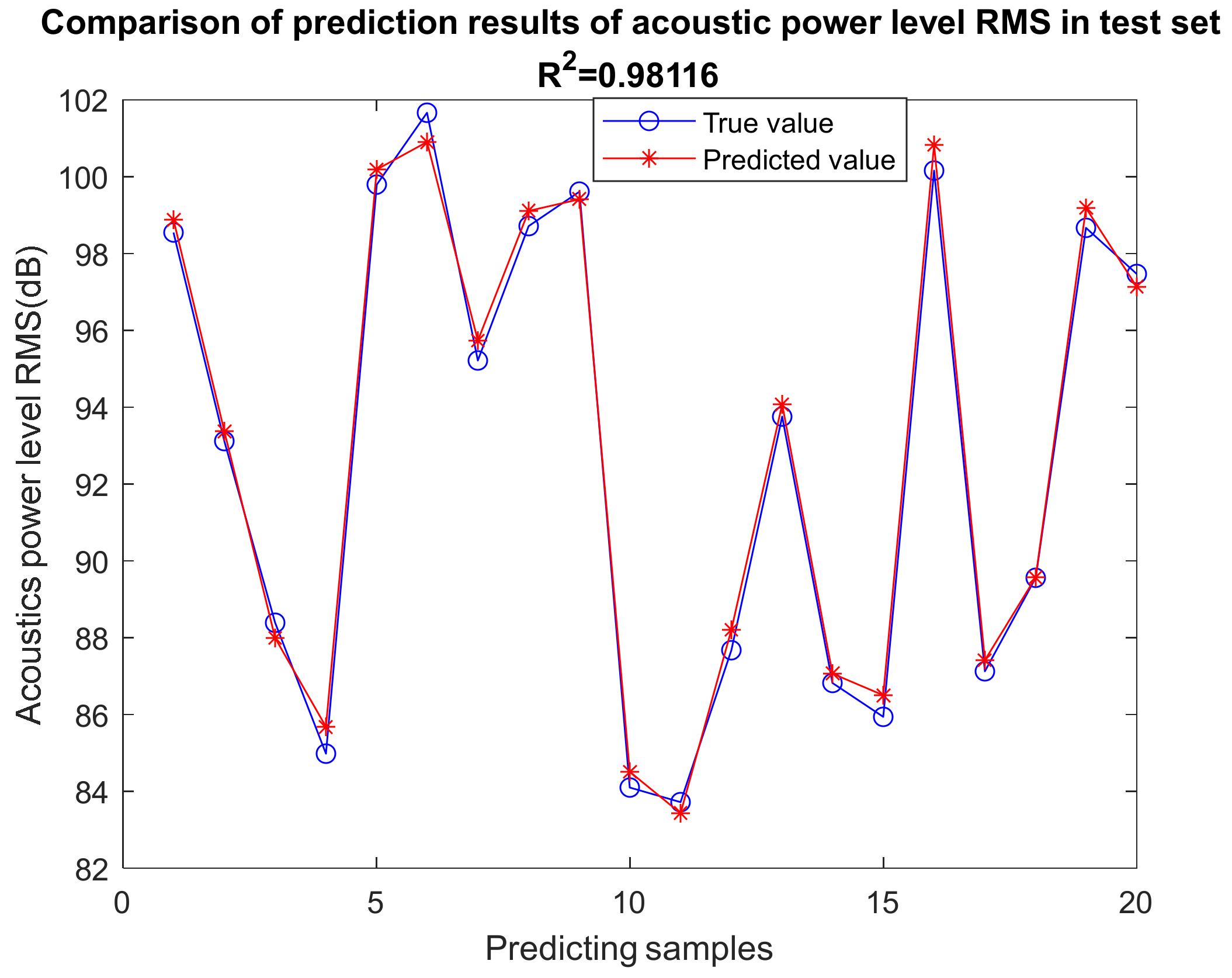
80% of the modification parameters-noise data were randomly selected as the training set of GRNN, and the remaining 20% were used to test the model. The number of neurons in the input layer was set to 3, the number of neurons in the mode layer was set to 100, and the transfer function was selected as Gaussian function to create the prediction model. The fitting effect of the test set of the GRNN on the data is illustrated in
Figure 12.
Generally speaking, when the goodness of fit R
2 reaches 0.9 or more, it indicates that the prediction model has a solid fitting ability. As is clear from
Figure 12, the goodness of fit R
2 of this model reaches 0.98116, which proves that the optimized model fits the gear modification parameter-radiation noise data set well, indicating that the constructed prediction model can accurately predict noise.
5. Establishing an Optimization Model of Gear Modification Parameters to Minimize Noise
A gear modification parameter optimization model is to minimize noise is constructed, and the model is solved by the particle swarm optimization (PSO) algorithm [
22]. The optimization goal of the model is shown in Equation (19), which represents the acoustic power level RMS value of the transmission system radiated noise; the constraint conditions are shown in Equation (20), which represents the modification range of the pinion drum modification amount, the tooth inclination, and the tooth profile modification amount.
Here: is the RMS value (dB) of the minimum acoustic power level corresponding to the scanning frequency band of the radiated noise; is the pinion tooth drum modification amount (µm); means the pinion tooth inclination amount (µm); represents the amount of pinion tooth profile modification (µm).
PSO uses particle swarms to search for the optimal particles in the solution space instead of the crossover and mutation operations of genetic algorithms. Simple and easy to implement; no need to adjust complex parameters.
The PSO algorithm solves the optimization model, sets relevant parameters, and obtains the optimal solution after optimization, as shown in
Table 8:
6. Effect Analysis of Gear Modification Noise Reduction Design Noise
The optimized combination of gear modification parameters is imported into Romax to establish the traction gear modification parametric mode. Unit load analysis, transmission error analysis, and vibration acceleration analysis of the gearbox are carried out in the process of dynamic simulation analysis under high-speed working conditions. The acoustic boundary element method is used for acoustic simulation analysis to obtain the RMS value of the acoustic power level. The gear transmission error value after the optimized modification is illustrated in
Table 9. The load distribution per unit length of the pinion and the wheel is illustrated in
Figure 13 and
Figure 14, and the acoustic power level curve is shown in
Figure 15. Compared with simulation analysis results before optimizing modification, as shown in
Table 10.
According to the data in
Table 8 and
Table 10, it can be seen that there is only a 0.83% error between the sound power level RMS value of 82.80 dB obtained by solving the model and the simulation value of 83.49 dB obtained through the actual simulation process of the optimal parameter, which verifies the GRNN model reliability. Furthermore, the gear transmission error after the modification has been reduced from 0.503 µm to 0.087 µm, a decrease of 0.416 µm, and the reduction rate is 89% compared with that before the modification; the unit load distribution of the gear set is improved from serious unbalanced load to uniform load; the RMS value of the acoustic power level was reduced from 96.59 dB to 83.49 dB, a 13.10 dB reduction, a 14% reduction. Since the simulation environment is different from reality, the transmission medium of gear transmission noise in the simulation environment is air, and there is no noise reduction work carried out during the transmission process. Therefore, in reality, the noise level that passengers hear in the train compartment should be lower. In a word, the research results show that the optimized result is excellent in noise reduction of the gear transmission system, thereby improving the passenger experience.
7. Conclusions
Given vibration and noise during the operation of the EMU, this study constructed a parametric modification model of the gear transmission system of the EMU, and a reasonable modification scheme is designed. The dynamic simulation analysis of the system is carried out to study its dynamic characteristics. The boundary element method is used to solve the radiated noise of the transmission system, and the modified parameter radiated noise prediction model is constructed by using the GRNN combined with Romax and Virtual. Lab, the optimization model of gear modification parameters, is established and solved by the PSO algorithm. The actual simulation results show that the gear transmission error is considerably reduced. The contact spot is significantly improved, and the RMS value of the acoustic power level was decreased from 96.59 dB to 83.49 dB, a 13.10 dB reduction, a 14% reduction. It is shown that the design can effectively reduce the radiated noise of the gear transmission system and improve the comfort of passengers. This study overcomes the shortcomings of using indirect indicators such as contact load or vibration to reflect the noise reduction effect but directly solves the radiated noise of gear transmission. Moreover, coupled with the intelligent algorithm to optimize, the experimental results are under a certain degree of guiding significance for the study on EMU modification and noise reduction. The main contributions of this paper are as follows:
- (1)
Taking the traction gear transmission system of a certain EMU under high-speed working conditions as the research object, a dynamics and sound radiation simulation process is established to solve the noise level of the gear transmission system. Based on the parametric modification model of the gear, the batch acquisition of gear transmission noise simulation data with different modification parameters is realized.
- (2)
GRNN is used to explore the mapping relationship between gear modification parameters and gear transmission radiated noise and build a modification parameter-noise prediction model. Then, with the explicit goal of reducing noise, the shaping parameters’ optimization model is established, the particle swarm algorithm is introduced to solve the model, and the optimal shaping parameter values are obtained. Based on the obtained simulation data, the prediction output data and the simulation output data are mutually confirmed to ensure the validity and accuracy of the prediction model and the optimal solution.
There will inevitably be some omissions in this research, and there is still much work to be studied. Hope to further supplement and improve in future research:
- (1)
Due to the limited experimental conditions, the experimental process of this study is limited to computer simulation, and the results are not verified in practical application. In future work, simulation combined with practical application can be used to do further research.
- (2)
This research only considers the high-speed working conditions of the gear transmission system, and the working conditions of the gear transmission system in the actual operation of the EMU are complicated and changeable. Establishing the optimization criteria for the modification design of the EMU gear transmission system under multiple working conditions needs further study.


