Article

High Temperature Mechanical Properties and Microstructure Evolution of Ti-6Al-4V Alloy Linear Friction Welding Joints

School of Mechanical Engineering and Automation, Beihang University, Beijing 100191, China
*
Author to whom correspondence should be addressed.
Machines 2022, 10(2), 151; https://doi.org/10.3390/machines10020151
Submission received: 19 January 2022 / Revised: 14 February 2022 / Accepted: 14 February 2022 / Published: 18 February 2022
(This article belongs to the Section Advanced Manufacturing)

Abstract

:
The combination of linear friction welding (LFW) and hot forming processes is limited due to a lack of research on the high-temperature flow behavior and microstructure evolution of welded joints. In this paper, an electric-assisted high-temperature uniaxial tensile test platform based on digital image correlation (DIC) is built, and uniaxial tensile tests of Ti-6Al-4V alloy with LFW joints are performed at different temperatures (923–1023 K) and different strain rates (0.001 s−1–0.01 s−1). Then the microstructure of the LFW joints under different hot deformation conditions have been analyzed by scanning electron microscope (SEM), electron backscatter diffraction (EBSD) and transmission electron microscopy (TEM). The results indicate that the high-temperature flow behavior of LFW joints shows an obvious correlation between temperature and strain rate: the yield stress decreases from 203 MPa at 923 K to 105 MPa at 1023 K, and increases from 85 MPa to 130 MPa when the strain rate increases from 0.001 s−1 to 0.01 s−1 at 973 K. The hot deformation mechanisms with deformation conditions have been characterized, which changes from the mechanism of dislocation creep to the mechanism of self-diffusion as the deformation temperature increases from 923 to 1023 K. Especially, the fraction of high angle boundaries (HABs) rapidly rise from 49.2% to 64.1% with the increasing temperatures, the discontinuous dynamic recrystallization (DDRX) become the primary mechanism of nucleation during high-temperature deformation of LFW joints.

1. Introduction

Titanium alloys are highly used for the curvature structure of aircraft, like wings, reinforced frames, and other loading bearing components due to their excellent mechanical properties and electrochemical properties [1,2,3,4,5,6]. Hot stretch forming (HSF) was developed by Cyril Bath Company to solve the problem of poor formability of titanium alloys at ambient temperature. It can realize structural integrity and rapidly integrated form of equal section titanium alloy structure. However, the forming of integral components with high rib complex shapes (e.g., bulkhead) still has limitations [7,8].
Beyond the production of bladed disks (BLISKs) [9], Linear friction welding (LFW) has been proved to be capable of producing net-shape complex titanium pre-forms in the aerospace industry in recent years because of its reliability, low cost, and excellent welding joint quality as an effective connection technique for complicated cross-section parts. The principle is that the smaller workpieces are linked into a pre-form, then machined to the desired size. McAndrew [10] claimed that the LFW technique can produce up to 50% of titanium alloy structural aerospace components such as wings, load-bearing frame beams. Thompson company [11] manufactured the primary bearing wing rib of an aircraft using a combination of linear friction welding and numerical control machining, increasing material usage by more than 40%.
Aside from connecting workpieces with a single-sided surface [12,13,14], various research [10,15,16] are actively investigating non-planar faying surface welding in aero-structures. The Boeing Company and TWI [10] are devoted to uniting trapezoid-shaped workpieces and proposing the multi-contact welding process. Romilly [15] performed an LFW test on a U-shaped geometry and discovered that an over-consuming upset would not influence weld quality, and consuming some material on the branches before beginning consuming on the bottom is a good choice for the non-planar faying surface. Moffath [16] firstly combined LFW with the hot forming process to manufacture titanium alloy curvature structural components, as seen in Figure 1. Firstly, the reinforced rib is welded on the titanium alloy profile by LFW, and then the curvature structure is created by HSF, the final part is obtained after NC machining. This composite forming process can be used for integrated and low-cost production of difficult-to-form materials at room temperature, particularly titanium alloys. However, few researchers have studied the high-temperature mechanical properties of LFW joints, the mechanism of high-temperature mechanical properties of welded joints is unknown, limiting the combination of LFW and other hot forming processes.
Many academics have conducted experimental studies on the mechanical properties of linear friction welding joints at room temperature. Wanjara et al. [17] investigated the effect of welding process parameters on the tensile properties of welded joints at room temperature. Tensile strength decreases and elongation increases as vibration frequency increases, whereas amplitude and friction pressure have little effect on the joint’s tensile strength. Li et al. [18] studied the effect of process parameters on the tensile properties of Ti-6Al-4V (TC4) joint and discovered that the tensile strength and plastic properties of the welded joint reached or even exceeded the base metal, and the weld joint performance is consistent with the results of other titanium alloys reported in other studies [19]. Wang [20] conducted the influence of heat treatment on the mechanical behavior of Ti-6.5Al-3.5Mo-1.5Zr-0.3Si (TC11) alloys, finding that both pre-weld and post-weld heat treatments can enhance the tensile strength while decrease joint elongations. Romero et al. [21] analyzed the micro-hardness of TC4 welded joints and considered that the micro-hardness shape of the whole welded joint takes the form of “W”, and the micro-hardness reaches its maximum in the weld zone, which is consistent with the findings of Wanjara [17].
Some researchers have investigated the microstructure development of linear friction welded joints. Karadge et al. [22] discovered that the weld center zone is a widmanstatten structure composed of refined β grains when the cooling rate approaches 410 K/s. Li et al. [19] found that the weld center zone of TC17 alloy has a fine equiaxed α + β structure, and the α and β grains distributed along the deformation direction in the heat-affected zone (HAZ). According to Frankel et al. [23], the thermo-mechanical affect zone (TMAZ) experiences some minor recrystallization phenomenon since its temperature can reach the β transit temperature. The present research focuses on the impact of various welding process parameters and heat treatment methods on the microstructure of welded joints, but it does not investigate the microstructure evolution of joints during subsequent secondary high-temperature deformation.
However, the study of linear friction welded joints focuses primarily on the microstructure characteristics and the evaluation of mechanical properties at room temperature. The investigation of the microstructure evolution and mechanical behavior laws of welded joints associated with high-temperature deformation is critical. It may not only drive the use of linear friction welding technology in conjunction with other hot forming techniques, but it can also provide guidance for the precision forming of complicated structural members. As a result, the paper offers a detailed study of the high-temperature mechanical properties and microstructure evolution of the LFW joints, with the aim of combining the LFW process with the hot forming process to provide new process guidance for the fabrication of complex titanium alloy structural parts. Then the effects of deformation temperature and strain rate on microstructure evolution were discussed. Consequently, this research could expand the LFW high-temperature material library and broaden the industrial application of this promising process.

2. Materials and Methods

2.1. Material

Baoji Titanium Industry Company Limited provided the TC4 extrusion profiles used in this work, the alloys were extruded at 1050 °C and then heat treated at 750 °C for 2.5 h, and the chemical composition (in wt.%) is listed in Table 1. The TC4 linear friction welding process was tested in a linear friction welding machine (LFW-20T) developed by Beihang University, which is equipped with two hydraulic actuators [17]: the vibration diver could vibrate the workpieces, and the forging driver can apply upsetting force. The main specifications of the LFW welder are shown in Table 2. Table 3 lists the processing parameters chosen for this paper based on the relevant literature [17], including the amplitude, vibration frequency, and applied frictional pressure.

2.2. Current-Assisted High Temperature Uniaxial Tensile Test Platform

To accurately simulate the HSF process environment, we established a current-assisted high-temperature uniaxial tensile test platform, as illustrated in Figure 2. The high-temperature tensile specimen was obtained from the middle plane of the friction welding block perpendicular to the weld center zone. The platform consists of DDL-100 electronic universal testing machine, self-resistance heating system, digital image correlation (DIC) system, an infrared thermal imager temperature measurement system. Tensile force is accurately measured using the PSD-2tSJTH force sensor. It has a measurement range of 0.08–20 KN and an indicator accuracy of 0.3%. The DY-12V1000A type DC regulated constant current power supply with a current regulation accuracy of 0.01 A is used to heat specimens. By regulating the current in real-time, the stability of the sample temperature field is ensured during the test. According to Yuan [24], the gauge length is obtained by the temperature field of the sample using the Fotric 227 S infrared thermal imager. Finally, the DIC system is used to accurately measure the sample’s non-contact true strain. The high-temperature tests were 923–1023 K at 50 K intervals, and the strain rates were 0.001–0.1 s−1 at order magnitude intervals.

2.3. Microstructure Characterization

The titanium alloy rod tensile specimen is used in the single tensile test in this study. The gauge length is 22 mm, and the diameter is 3 mm. The sample is cut perpendicular to the weld center using the wire cutting method, and the tensile direction is parallel to the extrusion direction, as shown in Figure 3. The metallographic sample is quenched in water after the hot tension process to preserve the high-temperature microstructure.
Scanning Electron Microscopy (SEM, JSM-7900F, the acceleration voltage is 15 kV) and Transmission Electron Microscopy (TEM, Tecnia F30) were used to observe the microstructure characteristics of weld center zone (WCZ), thermo-mechanically-affected zone (TMAZ), and parent metal (PM) of tested specimens. Electron backscatter diffraction (EBSD, JSM-7900F) investigations were performed with the accelerating voltage of 20 kV, and the step size is 0.2 µm. The micro-hardness was measured by a THV-1(M)DT tester with a test load of 0.5 kg and a dwell time of 12 s.
The tested samples were prepared by mechanical grinding and polishing for further observation. Then the samples for EBSD and SEM were etched at 248 K for 45 s with a polishing solution of 5% HF + 65% CH3OH + 30% C4H9OH. And EBSD tests were conducted with a step of 0.2 μm in the region of 150 × 170 μm2. While for the TEM observation, the samples were prepared by first grinding samples to a thickness less than 100 μm and then a 3 mm thick disc is punched out, and the sample is prepared at 248 K in the double jet thinning instrument with a polishing solution of 4.8% HClO4 + 59.7% CH3OH + 35.5% C4H9OH.

3. Results

3.1. Tensile Flow Behavior at Elevated Temperatures

The true strain was controlled within 10% based on the HSF process to get accurate stress-strain data before localized necking. To study the effect of deformation temperature on the flow behavior of LFW joints, the true stress-strain curves (σε) of Ti-6Al-4V (TC4) at different deformation temperatures (923–1023 K) with strain rates 0.01 s−1 were shown in Figure 4a. All flow stress curves, including the elastic deformation and yield softening stages, have a similar variation pattern. In the elastic phase, the flow stress increases rapidly as the strain increases. Due to high-temperature softening, the stress curves show a declining tendency once the alloy has reached its peak value. It is concluded that the mechanical property of the LFW joint has an apparent temperature correlation. The 0.2% offset yield stress σ 0.2 [25] was defined at the yield stage to assess the yield strength of the material. The flow stress reduces as temperature increases, the yield stress σ 0.2 drops from 203 MPa to 105 MPa, and the stress difference between 973 K and 1023 K is around 100 MPa.
At 973 K, the effects of different strain rates on the flow behavior of LFW joints were investigated. Figure 4b depicts the true stress-strain curves (σε) at 973 K with different strain rates (0.001 s−1–0.01 s−1). The tension responses of TC4 profiles can be seen to have a positive strain rate correlation within 0.001 s−1 to 0.01 s−1. At 973 K, the yield stress σ 0.2 increases from 85 MPa to 130 MPa as the strain rates increase. The difference in stress between 0.001 s−1 and 0.01 s−1 is approximately 55 MPa.

3.2. Micro-Hardness Tests

The test sites for the micro-hardness test of the LFW joint are picked in the ED-TD plane, with one point every 60 µm near the weld region and one point every 100 µm near the base metal area, as shown in Figure 5a, and the test results are displayed in Figure 5b. The micro-hardness of the LFW joint is distributed symmetrically in a “W” shape in the extrusion direction: the WCZ has the highest hardness due to fine grain strengthening, with a hardness value of 408.9 HV; the TMAZ has a lower hardness value due to the thermal softening effect [21]. As it drifts away from the WCZ, the friction heat effect reduces and the hardness reaches 348 HV as well as the base metal hardness. Additionally, the micro-hardness of the LFW joint shows a single peak distribution in the transverse direction, which decreases from 408.9 HV at the center to 370 HV at the edge. The reason is that the cooling rate at the interface center is significantly higher than that at the edge during the cooling phase [26]. We can observe from the above results that faults are common in the TMAZ of the LFW joints during the high-temperature tension process.

3.3. SEM Obsevation

Figure 6 displayed the SEM backscattered micrographs of TC4 joints at various temperatures (i.e., 293, 923, 973, 1023 K) with a constant strain rate 0.01 s−1. The initial as-received microstructure of LFW joints was comprised of the weld zone and parent metal zone, which consists of almost a single α phase, and the volume fraction of α phase is estimated to be more than 90%, as shown in Figure 6a. The parent metal microstructure has a typical lamella structure with complete β grain and primary α phase lamellar ( α p ) within the grains. Additionally, the grain in the weld center is significantly finer than that in the base metal area, indicating that fine equiaxed α are distributed uniformly in β phase. The coarsening effects of fine grains are visible as the deformation temperature rises [27], and we can see from Figure 6b–d that the thickness of α lamellar increases slightly. Furthermore, as the temperature rises, fine second lamellar ( α s ) grains begin to appear along the original β grain boundary, increasing the fraction of equiaxed grains.

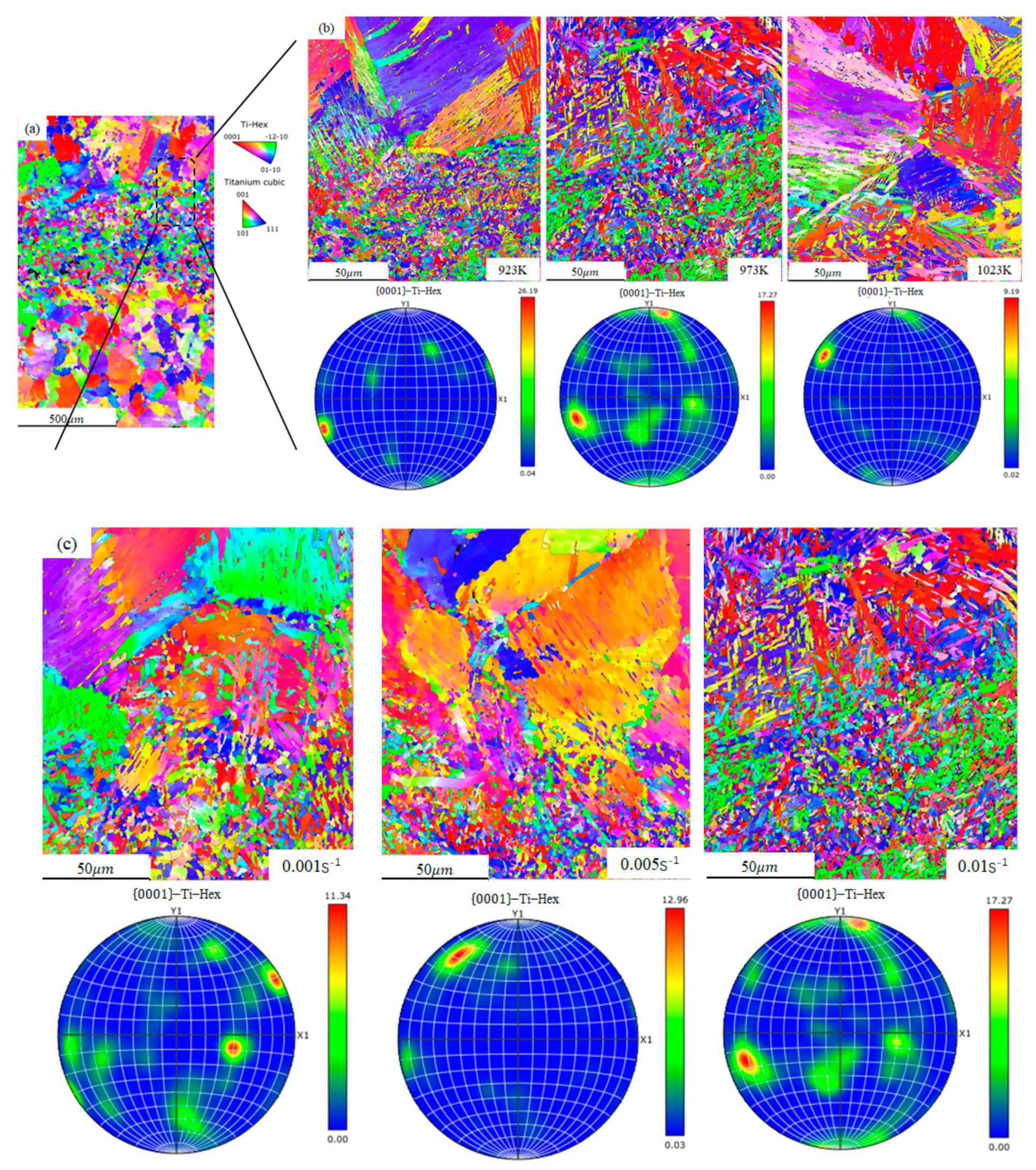
3.4. EBSD Observation

EBSD was used to further illustrate the grain orientation of different zones of LFW joints. Figure 7 displayed the EBSD analyses of the entire LFW joints. Similar to the microstructures as shown in Figure 6, we can conclude from Figure 7a that the widths of WCZ and TMAZ are approximately 0.8 mm and 0.2 mm, respectively. The base metal has a widmanstatten structure with distinct grain boundaries, and the weld zone has an equiaxed microstructure composed of ultrafine grains, which is also consistent with the results in Figure 6. Figure 7b depicts the grain orientation of LFW joints at different temperatures (923, 973, 1023 K), it is clear that all samples contained similar microstructure morphology: all of them consisted of primary α phase lamellar ( α p ), equiaxed α grains, fine second α lamellar ( α s ) and a few retained β phase. The mean grain size of the whole LFW joint increases from 36.1 μ m at 923 K to 39.7 μ m at 1023 K. Furthermore, the texture intensity of the α phase in (0001) basal decreases with increasing temperature. Figure 7c represents the grain orientation of LFW joints at various stain rates (0.001, 0.005, 0.01 s−1), we can also see that the evolution of microstructure is affected by strain rates such as deformation temperature. The average grain size rises from 22.1 μ m at 0.001 s−1 to 37.2 μ m at 0.01 s−1. Like other α titanium alloys [28], the directions in α phase texture are parallel to the TD, and the texture strength of alloy increases with the increase of strain rates.

4. Discussion

4.1. Hot Deformation Mechanism of LFW Joints

As mentioned in Figure 4, the morphologies of the true stress-strain curves under high temperatures are similar: flow stress decreases with the increase of temperature and the decrease of strain rate. Hot deformation behavior is usually attributed to grain growth [29,30], grain boundary sliding [31,32], and dynamic recovery and recrystallization [33,34]. Firstly, the thermal deformation behavior of the alloy is described by Arrhenius kinetic rate Equation [35]:
ε ˙ = A σ n e x p ( Q R T )
where T is the absolute temperature in Kelvin (K), A is a material constant, R is a gas constant (8.314 Jmol−1 K−1), ε ˙ is the strain rate, n is the stress index, and σ is the flow stress (MPa), Q is the activation energy (KJ mol−1).
To calculate the kinetic parameters n and Q, and the Equation (1) can be expressed as:
l n ( ε ˙ ) = l n ( A ) + n l n ( σ ) Q R T  
Thus, when ε ˙ is constant and apply partial derivative of Equation (2), the activation energy Q can be written as:
Q = R 1 m l n σ l n ( 1 / T ) | ε ˙  
where m is the strain rate sensitivity, which is the inverse of the stress index n
m = l n σ l n ( ε ˙ ) | T  
From the above Equations (2)–(4), the value of calculated Q and n under different strain rates and temperatures can be calculated by Equation (3). The results are listed in Table 4. The activation energy Q decreases from 323.9 to 220.7 KJ mol−1 with the temperature rising from 923 to 1023 K. Furthermore, the values of Q increases from 266.5 to 292.8 KJ mol−1 as the strain rate increases from 0.001 to 0.01 s−1.
It is obviously to conclude that the hot deformation mechanism of LFW joints varies depending on the deformation conditions based on flow stress behavior and activation energy. The calculated activation energy is 323.9 KJ mol−1 when the temperature is 923 K with the strain rate is 0.01 s−1. The obtained activation energy is close to the apparent deformation activation energy of α-Ti (346 KJ mol−1) and lies within the dislocation creep activation energy of α-Ti (200–360 KJ mol−1) [36]. Consequently, the hot deformation mechanism under 923 K with strain rate 0.01 s−1 is primarily controlled by the mechanism of dislocation creep, as described by He [27]. As the deformation temperature reaches 1023 K, the calculated activation energy and stress index decrease to 220.7 KJ mol−1 and 4.13, respectively. The activation energy value is much closer to the self-diffusion activation energy of β-Ti (153 KJ mol−1) [37] and α-Ti (204 KJ mol−1) [38]. Therefore, it can be concluded that the hot deformation mechanism may shift from dislocation creep to self-diffusion as the deformation temperature increases from 923 to 1023 K.

4.2. Effect of Temperature and Strain Rates on Microstructure Evolution

4.2.1. Grain Morphology and Size after Hot Deformation with Different Temperatures

Figure 6 and Figure 7 show that the LFW joints are composed of WCZ (complete dynamic recrystallization), TMAZ (partial dynamic recrystallization), and PM (lamellar structure). Following complex secondary deformation, the micromorphology of different regions will be significantly different, affecting the mechanical properties of each region and leading to uneven deformation of the joint. Figure 2 and Figure 3 show that despite the true strain of the welded joint being very small (≤0.1), the gauge length of the high-temperature tensile test exhibits a necking trend. Therefore, we need to conduct more quantitative research on the microstructure evolution under various thermal deformation conditions.
Figure 8 illustrated the evolution of grain morphology and average grain size at different temperatures. The WCZ dynamic crystallization generates an equiaxed structure with fine grains, with an average grain size of about 2 μ m [18,19]. Because heat conduction in the WCZ influences the heat-affected zone, the temperature near the welding center is high, the deformation is large, and the grain size is small, whereas the temperature near the base metal zone is low, the deformation is small, and the grain size is large. The microstructure is characterized by partial dynamic recrystallization [10], with a lower strength than that of the base metal and weld zone. Because the base metal area is far from the weld, its microstructure is unaffected and the original lamellar structure is preserved. Furthermore, the average grain size of different zones changed as the temperature increased: the mean value of WCZ rises from 1.9 μ m at 923 K to 2.3 μ m at 1023 K, and the thickness of α lamellae increases slightly due to the lamellae globularization phenomenon [27], as seen in Figure 8. According to Seshacharyulu et al. [39], lamellae globularization occurs frequently during the hot deformation process of titanium alloy and promotes the rotation of subgrains to relieve the dislocation concentration or the formation of high angle boundaries. The average grain size in PM increased from 43 μ m at 923 K to 48.4 μ m at 1023 K, whereas the grain size in TAMZ changed little: the value firstly decreased from 38.4 to 36.1 μ m , and then increased to 39.7 μ m . The reason is that some fine grains appear along the β grain boundary, but they do not have enough time to fully develop due to the low deformation temperature (1023 K) and small strain (0.1) [40]. The grain size evolution law is consistent with the development hardness test results in Figure 5, and grain boundary strength decreases as grain size increases. According to Hall-Petch relationship [41], this explains why the strength distribution of linear friction welded joints differs.

4.2.2. Grain and Subgrain Boundary (GSB) Structure Evolution after Hot Deformation

The grain subgrain boundary (GSB) evolutions at different temperatures with strain rates of 0.01 s−1 are shown in Figure 9. Previous researchers [27,42] defined and marked low angle boundaries (<5°, LAB), medium angle boundaries (5°–15°, MAB) and high angle boundaries (>15°, HAB) in the GSB image with blue, purple, and red lines, respectively.
Figure 9 illustrated the GSB maps with different deformation temperatures at a strain rate of 0.01 s−1. With increasing deformation temperature, it is clear that the fraction of LAB (blue lines) decreases while the intensity of HAB (red lines) increases. Moreover, as seen in magnification map Figure 9a–c, there are increasingly equiaxed grains with HABs appearing along the original coarse grain boundaries. According to He [27,42], these new fined grains without medium and low angle boundaries are considered to be the potential nucleation sites of newly formed recrystallized grains, which is associated with the high-temperature softening effects.
The microstructure evolution during the high deformation process is highly reliant on Dynamic recrystallization (DRX), which can generate huge numbers of new grains with HABs, thus playing a significant role in the dynamic softening process [42]. To quantitatively describe the effects of subgrain rotation on the DRX nuclei, the number fraction of different orientation angles at different temperatures is summarized in Figure 10. The number fraction of LABs decreases from 42.7% at 923 K to 30.1% at 1023 K, which is transferred to HABs at the higher temperature. Therefore, the fraction of HABs rises rapidly from 49.2% to 64.1% with the increase of temperature. Furthermore, the fractions of MABs remain relatively low (less than 7%) as the temperature in the hot forming process increases [42], which contradicts the mechanism of continuous dynamic recrystallization (CDRX) [43,44]. As a result, discontinuous dynamic recrystallization (DDRX) has emerged as the primary mechanism of nucleation during LFW joint deformation at high temperatures. With increasing temperature, small “new” grains (color grains) appear, which affect the macroscopic mechanical behavior by changing grain orientation or dynamic recrystallization [34], resulting in the flow stress of 923 K is higher than that of 1023 K.

4.2.3. Temperature and Strain Rate Effect on GND Evolution

Dislocation density is not only closely related to the properties of materials but also an important factor affecting the microstructure evolution of materials. In this paper, EBSD is used to quantitatively evaluate the geometrically necessary dislocation (GND) density for predicting the total stored dislocation density [45], and the dislocation morphology was observed by the TEM technique. Figure 11 illustrated the GND evolution of LFW joints at different temperatures. The mean GND density of as-received materials is quantified as 25.53 × 1014 m−2 and the initial microstructure has high stored dislocation energy, as described in Figure 11a, and the detailed observation indicated that the dislocation density of the coarse β grain is lower than that of the WCZ. With the increase of deformation temperature, the average GND dropped from 27.62 × 1014 m−2 at 923 K to 25.49 × 10¹⁴ m−2 at 1023 K. Moreover, as shown in magnification map Figure 11b,c, there are some small grains appearing along the β grain boundaries, similar to the GSB distribution of Figure 9, which implies that dislocation accumulation at grain boundaries and the formation of subgrain boundaries accelerated as a result of CDRX [46,47].
Figure 12 illustrated that the GND evolution of LFW joints at different strain rates at 973 K. As the increase of strain rate, the average GND rised from 27.65 × 10¹⁴ m−2 at a strain rate of 0.001 s−1 to 25.49 × 10¹⁴ m−2 at a strain rate of 0.001 s−1. Clearly, the GND has a positive correlation with strain rate. However, the difference in hot forming time due to strain rate is small (true strain < 0.1), resulting in insufficient grain production, the difference in dislocation density is also small. The main effect of strain rate on flow stress curve is to change grain orientation or increase subgrain boundary [48]. Therefore, we can see from Figure 4b that when the strain rate increases from 0.001 s−1 to 0.1 s−1, the flow stress value increases from 85 to 130 MPa.
TEM technique is used to further characterize the dislocation morphology of α matrix and α/β interface at different temperatures, as shown in Figure 13. As seen in Figure 13a,d, as the strain increases, the dislocation in the α/β interface and α phase will gather rapidly and form a dislocation pile-up, which leads to a rapid increase in flow stress. And the dislocation density in the grain boundary and α phase is high at 923 K. The dislocation pile-up remained and the dislocation net appeared in the α phase as the temperature rises to 973 K. As shown in Figure 13b, the dislocation was primarily concentrated at the α/β interface, and the density of dislocations decreased. Temperature increases the rate of formation of subgrain boundaries, resulting in a decrease in dislocation density [49]. The dislocation density is low at the α/β interface and the α matrix, as shown in Figure 13c,f. As the deformation temperature rises, the phenomenon of dynamic recrystallization becomes more visible, and fine second α phase grains appear in the β matrix. Recrystallization can form HABs and change grain orientation, resulting in more free dislocation movement and wider dislocation spacing, lowering dislocation density and flow stress, according to Zhang [50].

5. Conclusions

In this paper, the high-temperature flow behaviors of TC4 LFW joints and its microstructure evolution under different temperature and strain rates have been investigated. The main conclusions are as follows:
1.
Despite that the high-temperature flow behavior of LFW joints shows a clear correlation between temperature and strain rate, all the flow stress curve exhibits a similar trend: Once the alloy has reached its peak value, the stress curves show a declining tendency due to high-temperature softening. The yield stress σ 0.2 drops from 203 MPa at 923 K to 105 MPa at 1023 K, and rises from 85 MPa to 130 MPa with the strain rates increases from 0.001 s−1 to 0.01 s−1 at 973 K.
2.
The hot deformation mechanism of LFW joints are various under different deformation conditions: the hot deformation mechanism changes from the mechanism of dislocation creep to the mechanism of self-diffusion as the deformation temperature increases from 923 to 1023 K.
3.
The fraction of HABs rapidly rises from 49.2% to 64.1% with the increase of temperature, the discontinuous dynamic recrystallization (DDRX) become the primary mechanism of nucleation during high-temperature deformation of LFW joints.
4.
The grain size in different regions of welded joints has different variation trends: the average grain size in PM increased from 43 μ m at 923 K to 48.4 μ m at 1023 K, while the grain size in TAMZ firstly decreased from 38.4 to 36.1 μ m , then increased to 39.7 μ m due to recrystallization. It is widely existed in hot deformation process of LFW joints and it will promote the rotation of subgrain to relieve the dislocation pile-up or promote the formation of high angle grain boundaries.

Author Contributions

This article is the result of the joint efforts of several authors. Conceptualization, D.L. and X.L.; Formal analysis, C.Z. and X.L.; Methodology, C.Z. and Y.L.; Resources, D.L. and X.L.; Writing—original draft, C.Z.; Writing—review & editing, Y.L.; Literature search, Q.X. All authors have read and agreed to the published version of the manuscript.

Funding

This research was funded by the National Natural Science Foundation of China (51975032), National Natural Science Foundation of China (51775023).

Institutional Review Board Statement

Not applicable.

Informed Consent Statement

Not applicable.

Data Availability Statement

The data presented in this study are available on request from the corresponding author.

Acknowledgments

Special thanks to Liu Xiaochun (Changsha University of Science &Technology) for his support in microstructure characterization. The authors appreciate for their support.

Conflicts of Interest

This article does not contain any studies with human participants or animals performed by any of the authors. Therefore, ethics approval is not applicable. The authors declare no competing interests.

References

  1. Boyer, R.R. An overview on the use of titanium in the aerospace industry. Mater. Sci. Eng. A 1996, 213, 103–114. [Google Scholar] [CrossRef]
  2. Li, C.-L.; Mi, X.-J.; Ye, W.-J.; Hui, S.-X.; Yu, Y.; Wang, W.-Q. A study on the microstructures and tensile properties of new beta high strength titanium alloy. J. Alloys Compd. 2012, 550, 23–30. [Google Scholar] [CrossRef]
  3. Li, Y.; Loretto, M.; Rugg, D.; Voice, W. Effect of heat treatment and exposure on microstructure and mechanical properties of Ti–25V–15Cr–2Al–0.2C (wt%). Acta Mater. 2001, 49, 3011–3017. [Google Scholar] [CrossRef]
  4. Odenberger, E.-L.; Pederson, R.; Oldenburg, M. Finite element modeling and validation of springback and stress relaxation in the thermo-mechanical forming of thin Ti-6Al-4V sheets. Int. J. Adv. Manuf. Technol. 2019, 104, 3439–3455. [Google Scholar] [CrossRef] [Green Version]
  5. Guo, G.; Li, D.; Li, X.; Deng, T.; Wang, S. Finite element simulation and process optimization for hot stretch bending of Ti-6Al-4V thin-walled extrusion. Int. J. Adv. Manuf. Technol. 2017, 92, 1707–1719. [Google Scholar] [CrossRef]
  6. Liu, B.; Liu, Y.B.; Yang, X.; Liu, Y. TITANIUM 2008: Development of international titanium industry, preparation technology and applications. Mater. Sci. Eng. Pow. Metall 2008, 14, 67–73. [Google Scholar]
  7. Zhao, Y.; Guo, H.; Shi, Z.; Yao, Z.; Zhang, Y. Microstructure evolution of TA15 titanium alloy subjected to equal channel angular pressing and subsequent annealing at various temperatures. J. Mater. Process. Technol. 2011, 211, 1364–1371. [Google Scholar] [CrossRef]
  8. Yang, H.; Fan, X.G.; Sun, Z.C.; Guo, L.; Zhan, M. Some advances in local loading precision forming of large scale integral complex components of titanium alloys. Mater. Res. Innov. 2011, 15, s493–s496. [Google Scholar] [CrossRef]
  9. Li, W.; Vairis, A.; Preuss, M.; Ma, T. Linear and rotary friction welding review. Int. Mater. Rev. 2016, 61, 71–100. [Google Scholar] [CrossRef]
  10. McAndrew, A.R.; Colegrove, P.; Bühr, C.; Flipo, B.C.; Vairis, A. A literature review of Ti-6Al-4V linear friction welding. Prog. Mater. Sci. 2018, 92, 225–257. [Google Scholar] [CrossRef]
  11. McAndrew, A.R.; Flipo, B.C.D. Linear Friction Welding for Near Net Shape Manufacturing of Titanium Alloy Ti-6Al-4V Aerospace Components. In Proceedings of the 2018 9th International Conference on Mechanical and Aerospace Engineering (ICMAE), Budapest, Hungary, 10–13 July 2018; pp. 126–130. [Google Scholar] [CrossRef]
  12. Zhao, P.; Fu, L.; Zhong, D. Numerical simulation of transient temperature and axial deformation during linear friction welding between TC11 and TC17 titanium alloys. Comput. Mater. Sci. 2014, 92, 325–333. [Google Scholar] [CrossRef]
  13. Vairis, A.; Frost, M. High frequency linear friction welding of a titanium alloy. Wear 1998, 217, 117–131. [Google Scholar] [CrossRef]
  14. Dalgaard, E.; Wanjara, P.; Gholipour, J. Linear Friction Welding of a Forged Near-α Titanium Alloy. Mater. Sci. Forum 2012, 706–709, 211–216. [Google Scholar]
  15. Romilly, P. Linear Friction Welding for Near Net Shape Manufacturing of Titanium Parts. In Proceedings of the 13th World Conference on Titanium, Hoboken, NJ, USA, 16–20 August 2015; pp. 1423–1427. [Google Scholar] [CrossRef]
  16. Moffat, M.; Romilly, P. Breakthrough technologies in aerospace industry for titanium processing. In Proceedings of the Titanium Europe 2014 Conference, Sorrento, Italy, 19–21 March 2014. [Google Scholar]
  17. Wanjara, P.; Jahazi, M. Linear friction welding of Ti-6Al-4V: Processing, microstructure, and mechanical-property inter-relationships. Met. Mater. Trans. A 2005, 36, 2149–2164. [Google Scholar] [CrossRef]
  18. Li, W.-Y.; Ma, T.; Li, J. Numerical simulation of linear friction welding of titanium alloy: Effects of processing parameters. Mater. Des. 2010, 31, 1497–1507. [Google Scholar] [CrossRef]
  19. Li, W.-Y.; Ma, T.; Yang, S. Microstructure Evolution and Mechanical Properties of Linear Friction Welded Ti-5Al-2Sn-2Zr-4Mo-4Cr (Ti17) Titanium Alloy Joints. Adv. Eng. Mater. 2010, 12, 35–43. [Google Scholar] [CrossRef]
  20. Wang, X.Y.; Li, W.Y.; Ma, T.J.; Yang, X.W. Effects of Pre- and Post-weld Heat Treatments on Microstructure and Mechanical Properties of Linear Friction Welded TC11 Titanium Alloy Joints. J. Net-Shape Form. Eng. 2019, 11, 1–7. [Google Scholar]
  21. Romero, J.; Attallah, M.; Preuss, M.; Karadge, M.; Bray, S. Effect of the forging pressure on the microstructure and residual stress development in Ti–6Al–4V linear friction welds. Acta Mater. 2009, 57, 5582–5592. [Google Scholar] [CrossRef]
  22. Karadge, M.; Preuss, M.; Lovell, C.; Withers, P.; Bray, S. Texture development in Ti–6Al–4V linear friction welds. Mater. Sci. Eng. A 2007, 459, 182–191. [Google Scholar] [CrossRef]
  23. Frankel, P.; Preuss, M.; Steuwer, A.; Withers, P.; Bray, S. Comparison of residual stresses in Ti–6Al–4V and Ti–6Al–2Sn–4Zr–2Mo linear friction welds. Mater. Sci. Technol. 2009, 25, 640–650. [Google Scholar] [CrossRef]
  24. Chen, Y.; Li, S.; Li, Y.; Wang, Y.; Li, Z.; Lin, Z. Constitutive modeling of TA15 alloy sheet coupling phase transformation in non-isothermal hot stamping process. J. Mater. Res. Technol. 2021, 12, 629–642. [Google Scholar] [CrossRef]
  25. Park, S.H.; Lee, J.H.; Moon, B.G.; You, B.S. Tension–compression yield asymmetry in as-cast magnesium alloy. J. Alloys Compd. 2014, 617, 277–280. [Google Scholar] [CrossRef]
  26. Zhao, P.; Fu, L. Strain hardening behavior of linear friction welded joints between TC11 and TC17 dissimilar titanium alloys. Mater. Sci. Eng. A 2015, 621, 149–156. [Google Scholar] [CrossRef]
  27. He, D.; Zhu, J.; Lai, Z.; Liu, Y.; Yang, X. An experimental study of deformation mechanism and microstructure evolution during hot deformation of Ti–6Al–2Zr–1Mo–1V alloy. Mater. Des. 2013, 46, 38–48. [Google Scholar] [CrossRef] [Green Version]
  28. Lin, P.; He, Z.; Yuan, S.; Shen, J. Tensile deformation behavior of Ti–22Al–25Nb alloy at elevated temperatures. Mater. Sci. Eng. A 2012, 556, 617–624. [Google Scholar] [CrossRef]
  29. Rabinovich, M.; Trifonov, V. Dynamic grain growth during superplastic deformation. Acta Mater. 1996, 44, 2073–2078. [Google Scholar] [CrossRef]
  30. Li, F.; Bae, D.; Ghosh, A. Grain elongation and anisotropic grain growth during superplastic deformation in an Al-Mg-Mn-Cu alloy. Acta Mater. 1997, 45, 3887–3895. [Google Scholar] [CrossRef]
  31. Langdon, T.G. Seventy-five years of superplasticity: Historic developments and new opportunities. J. Mater. Sci. 2009, 44, 5998–6010. [Google Scholar] [CrossRef]
  32. Alabort, E.; Kontis, P.; Barba, D.; Dragnevski, K.; Reed, R. On the mechanisms of superplasticity in Ti–6Al–4V. Acta Mater. 2016, 105, 449–463. [Google Scholar] [CrossRef] [Green Version]
  33. McQueen, H. Development of dynamic recrystallization theory. Mater. Sci. Eng. A 2004, 387–389, 203–208. [Google Scholar] [CrossRef]
  34. Sakai, T.; Jonas, J.J. Overview no. 35 Dynamic recrystallization: Mechanical and microstructural considerations. Acta Metall. 1984, 32, 189–209. [Google Scholar] [CrossRef]
  35. Seshacharyulu, T.; Medeiros, S.; Frazier, W.; Prasad, Y. Microstructural mechanisms during hot working of commercial grade Ti–6Al–4V with lamellar starting structure. Mater. Sci. Eng. A 2002, 325, 112–125. [Google Scholar] [CrossRef]
  36. Song, H.-W.; Zhang, S.-H.; Cheng, M. Subtransus deformation mechanisms of TC11 titanium alloy with lamellar structure. Trans. Nonferrous Met. Soc. China 2010, 20, 2168–2173. [Google Scholar] [CrossRef]
  37. Balasubrahmanyam, V.; Prasad, Y. Deformation behaviour of beta titanium alloy Ti–10V–4.5Fe–1.5Al in hot upset forging. Mater. Sci. Eng. A 2002, 336, 150–158. [Google Scholar] [CrossRef]
  38. Bao, R.-Q.; Huang, X.; Cao, C.-X. Deformation behavior and mechanisms of Ti-1023 alloy. Trans. Nonferrous Met. Soc. China 2006, 16, 274–280. [Google Scholar] [CrossRef]
  39. Seshacharyulu, T.; Medeiros, S.; Morgan, J.; Malas, J.; Frazier, W.; Prasad, Y. Hot deformation and microstructural damage mechanisms in extra-low interstitial (ELI) grade Ti–6Al–4V. Mater. Sci. Eng. A 2000, 279, 289–299. [Google Scholar] [CrossRef]
  40. Zhang, S.; Lian, Y.; Chen, Y.; Sun, Y.; Feng, H.; Zhou, Y.; Cao, P. Hot Deformation Behavior and Microstructure Evolution of a TiBw/Near α-Ti Composite with Fine Matrix Microstructure. Metals 2019, 9, 481. [Google Scholar] [CrossRef] [Green Version]
  41. Hansen, N. Hall–Petch relation and boundary strengthening. Scr. Mater. 2004, 51, 801–806. [Google Scholar] [CrossRef]
  42. Liu, Z.; Li, P.; Xiong, L.; Liu, T.; He, L. High-temperature tensile deformation behavior and microstructure evolution of Ti55 titanium alloy. Mater. Sci. Eng. A 2017, 680, 259–269. [Google Scholar] [CrossRef]
  43. Mandal, S.; Bhaduri, A.K.; Sarma, V.S. A Study on Microstructural Evolution and Dynamic Recrystallization During Isothermal Deformation of a Ti-Modified Austenitic Stainless Steel. Met. Mater. Trans. A 2010, 42, 1062–1072. [Google Scholar] [CrossRef]
  44. Lin, Y.; Wu, X.-Y.; Chen, X.-M.; Chen, J.; Wen, D.-X.; Zhang, J.-L.; Li, L.-T. EBSD study of a hot deformed nickel-based superalloy. J. Alloys Compd. 2015, 640, 101–113. [Google Scholar] [CrossRef]
  45. Liang, X.; Dodge, M.; Jiang, J.; Dong, H. Using transmission Kikuchi diffraction in a scanning electron microscope to quantify geometrically necessary dislocation density at the nanoscale. Ultramicroscopy 2018, 197, 39–45. [Google Scholar] [CrossRef] [PubMed]
  46. Humphreys, F.J.; Rohrer, G.S.; Rollett, A. Recrystallization and Related Annealing Phenomena, 2nd ed.; Elsevier: Amsterdam, The Netherlands, 2004. [Google Scholar] [CrossRef]
  47. Momeni, A.; Ebrahimi, G.; Jahazi, M.; Bocher, P. Microstructure evolution at the onset of discontinuous dynamic recrystallization: A physics-based model of subgrain critical size. J. Alloys Compd. 2014, 587, 199–210. [Google Scholar] [CrossRef]
  48. Tahreen, N.; Zhang, D.; Pan, F.; Jiang, X.; Li, D.; Chen, D. Hot deformation and processing map of an as-extruded Mg–Zn–Mn–Y alloy containing I and W phases. Mater. Des. 2015, 87, 245–255. [Google Scholar] [CrossRef]
  49. Ma, L.; Wan, M.; Li, W.; Shao, J.; Han, X.; Zhang, J. On the superplastic deformation mechanisms of near-α TNW700 titanium alloy. J. Mater. Sci. Technol. 2021, 108, 173–185. [Google Scholar] [CrossRef]
  50. Zhang, X.; Cao, L.; Zhao, Y.; Chen, Y.; Tian, X.; Deng, J. Superplastic behavior and deformation mechanism of Ti600 alloy. Mater. Sci. Eng. A 2013, 560, 700–704. [Google Scholar] [CrossRef]
Figure 1. Schematic diagram of linear friction welding and hot stretch bending composite forming process (a) Titanium extruded profile; (b) Linear Firction Welding process; (c) Hot Stretch Formig process; (d) Final component.
Machines 10 00151 g001
Figure 2. Current-assisted high temperature uniaxial tensile test platform.
Machines 10 00151 g002
Figure 3. Cutting position and dimension diagram of unidirectional tensile specimen.
Machines 10 00151 g003
Figure 4. The true stress-strain curves (σ–ε) of LFW joints under different hot deformation conditions. (a) 923, 973, 1023 K; (b) 0.001, 0.005, 0.01 s−1.
Machines 10 00151 g004
Figure 5. Micro-hardness test of LFW joints (a) distribution of testing spots, (b) micro-hardness test results in extrusion direction (ED) and transverse direction (TD).
Machines 10 00151 g005
Figure 6. Microstructure of LFW joints at different deformation temperatures (a) 293 K, (b) 923 K, (c) 973 K, (d) 1023 K.
Machines 10 00151 g006
Figure 7. EBSD analyses of the microstructure in the LFW joints (a) the grain orientation map of the whole joints, (b) the (0001) pole figure and grain orientation of LFW joints at different temperature (923, 973, 1023 K), (c) the (0001) pole figure and grain orientation of LFW joints at different strain rates (0.001, 0.005, 0.01 s−1).
Machines 10 00151 g007
Figure 8. Evolution of grain morphology and size at different temperatures (923–1023 K). (a) grain orientation map of LFW joint; (b) Band contrast of LFW joint.
Machines 10 00151 g008
Figure 9. GSB maps of LFW joints obtained at different temperatures with a strain rate of 0.01 s−1: (a) 923 K, (b) 973 K, (c) 1023 K.
Machines 10 00151 g009
Figure 10. The number fraction of different orientation angle at different temperature with a strain rate of 0.01 s−1.
Machines 10 00151 g010
Figure 11. The GND evolution of LFW joints at different temperatures with a strain rate of 0.01 s−1: (a) 923 K, (b) 973 K, (c) 1023 K.
Machines 10 00151 g011
Figure 12. Geometrically necessary dislocation (GND) density with different strain rate at 973 K: (a) 0.001 s−1, (b) 0.01 s−1.
Machines 10 00151 g012
Figure 13. TEM characterization of α matrix and α/β interface in Ti-6Al-4V alloy during hot deformation: (a) 923 K, (b) 973 K, (c) 1023 K, (d) magnify view at 923 K, (e) magnify view at 973 K, (f) magnify view at 123 K.
Machines 10 00151 g013
Table 1. Chemical compositions of Ti-6Al-4V alloy profile (wt.%).
TiAlVFeON
balance6.264.220.100.130.01
Table 2. Specifications of the LFW-20T welder.
Frequency (Hz)Amplitude (mm)Applied Force (KN)Friction Force (KN)Control Mode
0–60 Hz0–4.50–2000–150Time, upset
Table 3. LFW parameters selected in this paper.
Frequency (Hz)Amplitude (mm)Friction Force (KN)Applied Force (KN)Upset (mm)
30 Hz2.825303.0
Table 4. Values of calculated n and Q under different deformation conditions.
Temperature/KStrain Rate/s−1nQ/(KJ mol−1)
9230.016.06323.9
9735.48292.8
10234.13220.7
9730.0015.48266.5
9730.0055.48279.0
Publisher’s Note: MDPI stays neutral with regard to jurisdictional claims in published maps and institutional affiliations.

