Article

Modeling and Characteristic Analysis of a Cylinder Block/Valve Plate Interface Oil Film Model for 35 MPa Aviation Piston Pumps

1
State Key Laboratory of Fluid Power and Mechatronic Systems, School of Mechanical Engineering, Zhejiang University, No. 38 Zheda Road, Hangzhou 310027, China
2
Zhejiang Development & Planning Institute, Hangzhou 310027, China
3
Aviation Science and Technology Key Laboratory of Aero Electromechanical System Integration, Nanjing Engineer Institute of Aircraft System Jincheng, AVIC, Nanjing 211100, China
*
Authors to whom correspondence should be addressed.
Machines 2022, 10(12), 1196; https://doi.org/10.3390/machines10121196
Submission received: 11 November 2022 / Revised: 4 December 2022 / Accepted: 5 December 2022 / Published: 9 December 2022
(This article belongs to the Special Issue Friction and Lubrication of Mechanical Drive Train Components)

Abstract

:
Oil film characteristics are critical to the high-reliability operation of high-pressure aviation piston pumps (APPs). However, there is still a lack of research on oil film modeling and characteristic analysis of high-pressure APPs. This paper takes the oil film at the cylinder block/valve plate interface of a 35 MPa high-pressure APP as the research object. By introducing a full oil film computational fluid dynamics (CFD) model considering non-isothermal and cavitation effects under multi-field coupling conditions, a cylinder block/valve plate interface oil film model is established, which includes a viscous wedge geometric model, multi-body dynamics model, and full oil film CFD model. The mesh independence test and force balance error analysis ensure the accuracy of the model calculation. Based on the established model, the oil film’s lubricating, sealing, load-bearing, and overturning characteristics are comprehensively and systematically analyzed, and the evolution law of different oil film characteristics with pressure changes is revealed. Moreover, suggestions for improving the structure and operating conditions of a 35 MPa high-pressure APP are proposed to optimize the oil film characteristics of the cylinder block/valve plate interface.

1. Introduction

The aviation piston pump (APP) is the core power component that converts mechanical energy into hydraulic energy and is usually called the “heart” of an aircraft hydraulic system [1]. The swash plate piston pump has become the most widely used APP due to its compact structure, small rotational inertia, large flow rate, and easy control of variables [2]. Unlike piston pumps used in other industrial scenarios, APPs embody the highest level of piston pump technology. APPs not only operate in harsh environments [3] (such as at high pressures (21∼35 MPa), in wide temperature ranges (−55∼135 °C), at high speeds (≥3000 rpm), and at high vibrations (≥30 g), etc. but also have high requirements for power density (≥6 kW/kg) and reliability (such as high mean time between failure (MTBF) (≥25,000 h) and long service life (≥35,000 h)). A focus on high power density and high reliability is one of the main trends in the development of APPs [4]. Studies have shown that increasing the operating pressure is the most effective way to increase the power density of APPs [5]. However, an increase in the operating pressure will destroy the oil film formation conditions in the lubricating interfaces and disturb the lubrication and state of the APP. Furthermore, it will lead to increased leakage or frictional wear, thereby reducing reliability and the life of the APP. The primary functions of the oil film are to provide lubrication, sealing, heat dissipation, and load bearing, which are some of the critical factors that determine the reliability of APPs. Excessive oil film thickness will lead to increased leakage and significantly reduced volumetric efficiency, thereby reducing the energy efficiency of APPs [6]. A small oil film thickness will increase Coulomb frictional and viscous frictional heating between components’ contact surfaces, thereby reducing torque efficiency. The above effects will further lead to the failure of the APP, such as vibration, noise, pulsation, a temperature increase, burned disk flaking, or sticky copper bite. Therefore, the ideal oil film formation conditions and appropriate oil film thickness distribution are key to the high reliability of high-pressure APPs.
The modeling and performance analysis of oil films are crucial for the highly reliable design, fabrication, and predictive maintenance of high-pressure APPs. Although researchers have conducted much research on oil film modeling and performance analysis [7,8,9], most of the research objects were not APP and the operating pressure of most piston pumps is lower than 35 MPa. The modeling of the oil film in a piston pump can be traced back to the parallel plate gap model, which can only analyze the simple leakage characteristics of an oil film with a fixed thickness, and the pressure is simplified to a logarithmic distribution [10,11,12]. After that, Yamaguchi et al. [13,14] and Bergada et al. [15] established the wedge-shaped oil film rigid model based on the 2D Reynolds equation and cylinder dynamics to analyze the micro-motion characteristics of the piston pump cylinder attitude. Since the 21st century, many researchers have considered power loss in oil film modeling, and the non-isothermal oil film model was established to analyze the multi-parameter coupling characteristics of oil film temperature–pressure–viscosity–density [16,17,18]. For the first time, Ivantysynova et al. [19,20] and Huang et al. [21] proposed a surface flexibility analysis method for lubricating interfaces that can consider pressure deformation, which indicates that the oil film analysis method has entered the elastohydrodynamic model stage. Based on this model, researchers analyzed the effect of component surface micro-topography on the lubricating performance of oil films [22,23,24]. According to Li et al. [25], Ivantysyn et al. [26], and Chacon et al. [27], oil film modeling has entered the stage of non-isothermal elastohydrodynamic models that can consider the surface temperature and pressure deformation, making it possible to analyze oil film characteristics with non-uniform thicknesses. However, there are few studies on oil film modeling and characteristic analysis of high-pressure APPs. To the best of the authors’ knowledge, there is no oil film model and systematic oil film characteristic analysis specifically for 35 MPa high-pressure APPs.
In an APP, the working area of the oil film at the cylinder block/valve plate interface is large and the force is complex. Unlike the oil film at the piston/cylinder block interface and slipper/swash plate interface, the oil film at the cylinder block/valve plate interface needs to balance forces and moments at the same time and is very sensitive to operating conditions such as pressure. The state of the oil film at the cylinder block/valve plate interface is one of the main factors that determine the reliability and service life of an APP. Therefore, this paper focuses on the modeling and characteristic analysis of the oil film at the cylinder block/valve plate interface. In this paper, an accurate cylinder block/valve plate interface oil film model is established for a 35 MPa high-pressure APP, the oil film characteristics are systematically analyzed, and the effects of pressure changes on different oil film characteristics are revealed. The main contributions are as follows: (1) A cylinder block/valve plate interface oil film model of a 35 MPa high-pressure APP is established by introducing a full oil film computational fluid dynamics (CFD) model considering the non-isothermal and cavitation effects under multi-field coupling conditions; the established model includes a viscous wedge geometric model, multi-body dynamics model, and full oil film CFD model; (2) Based on the established oil film model, the lubricating, sealing, load-bearing, and overturning characteristics of the oil film at the cylinder block/valve plate interface are comprehensively and systematically analyzed and the evolution law of different oil film characteristics with pressure changes is revealed; and (3) Suggestions for improving the structure and operating conditions of a 35 MPa high-pressure APP are proposed to optimize the oil film characteristics of a cylinder block/valve plate interface.
The remainder of this paper is organized as follows. Section 2 presents the operating principles of APPs and the formulation of the oil film modeling problem. In Section 3, detailed modeling of the cylinder block/valve plate interface oil film model is provided. Based on the established oil film model, the different characteristics of the oil film are comprehensively and systematically analyzed in Section 4. The conclusions are provided in Section 5.

2. Problem Formulation

An APP comprises rotating components, variable displacement components, oil-suction/discharge components, etc. It usually adopts the control mode of variable displacement with constant pressure to match the load demand, and its structure is shown in Figure 1. When the APP runs, the drive shaft transmits mechanical power (moment and speed) to the rotating components such as the cylinder block, piston, and slipper. As the piston rotates around the drive shaft, it also reciprocates axially so the volume of each piston chamber varies sinusoidally with the rotational angle of the drive shaft. When the piston chamber volume increases, negative pressure will be formed and the oil will enter the chamber through the oil-suction channel and oil-suction kidney groove. When the piston chamber volume decreases, the oil pressure increases and the oil is discharged from the pump through the oil-discharge channel and kidney groove. In this reciprocating operation, the APP can continuously convert the mechanical energy that drives the rotation of the drive shaft into hydraulic energy.
When the APP operates under full lubrication conditions, due to the combined action of the hydrodynamic effects produced by the relative motion of the components and the hydrostatic effects produced by the external pressure, a viscous oil film with a thickness of several microns to tens of microns is formed in the wedge-shaped gap of the lubricating interfaces. An oil film of an ideal thickness can withstand external loads and separate friction surfaces. When friction occurs within the oil film, the coefficient of friction is minimal, as well as the resulting wear. The oil film formation conditions are affected by the operating conditions (such as pressure, temperature, and rotational speed) and structural parameters of the APP.
Currently, the rated operating pressure of APPs is usually 21 MPa or 28 MPa [28]. When the pressure increases to 35 MPa, on the one hand, the thickness of the oil film decreases, the friction loss increases, and the lubricating and heat dissipation states of the oil film are destroyed. On the other hand, leakage and cylinder block overturning due to the pressure difference between the oil-suction and -discharge channel also increases, destroying the sealing and load-bearing state of the oil film. This paper focuses on the modeling and characteristic analysis of the oil film at the cylinder block/valve plate interface.

3. Oil Film Modeling
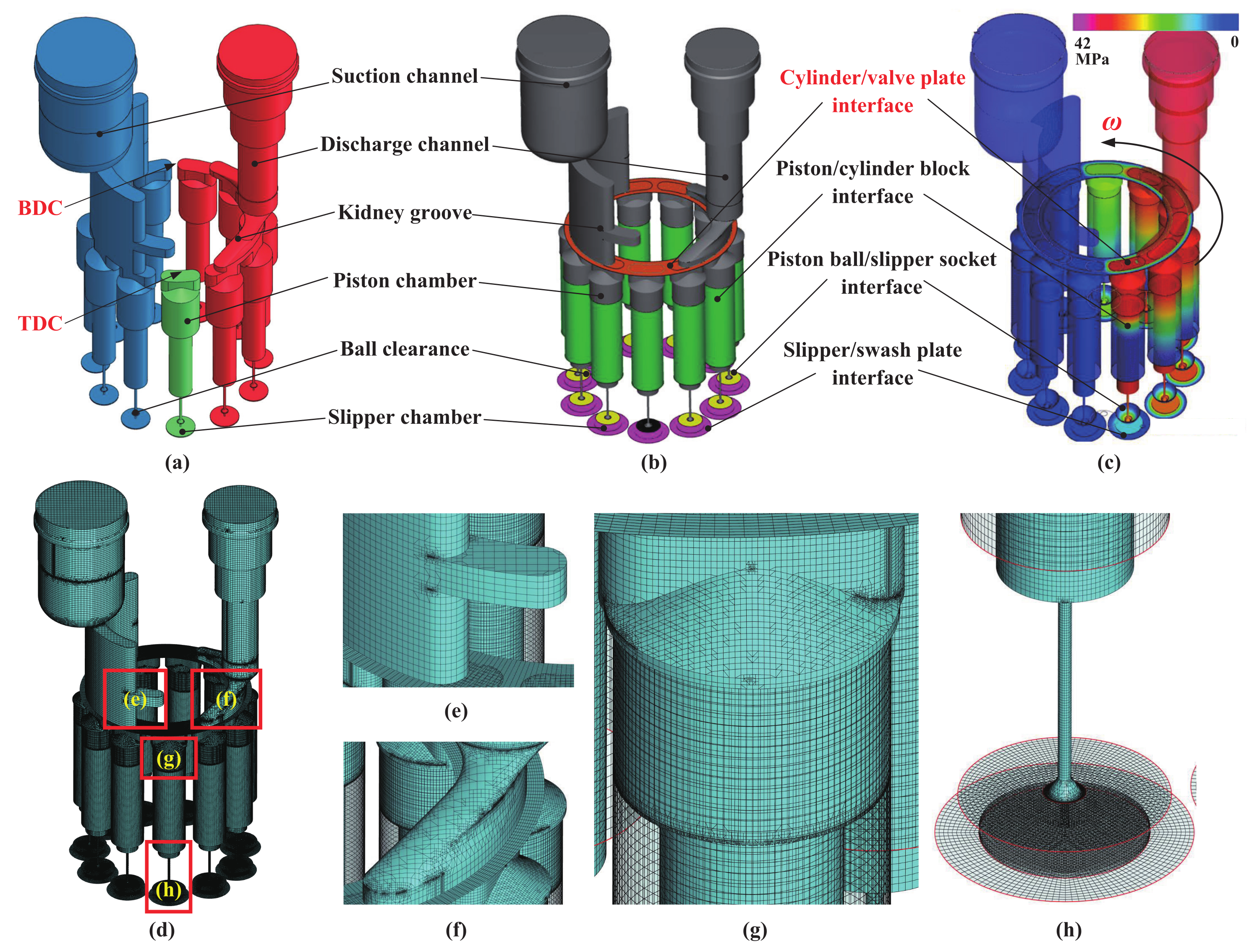
3.1. Model Overview

A valve plate is usually used in an end-mating APP. In addition to assisting the oil suction and oil discharge, the valve plate can also provide axial thrust for the rotating components such as the cylinder block, which is equivalent to an end thrust bearing [29]. The oil film exists at the cylinder block/valve plate interface and is mainly distributed in the inner sealing belt, outer sealing belt, and auxiliary support belt. As shown in Figure 2, the oil film is divided into discrete annular regions by the piston kidney groove of the cylinder block, the oil-suction and -discharge kidney groove, and the relief groove of the valve plate. The oil film pressure needs to be constantly changed to match the external load changes caused by the inertial forces of the rotating components. Unlike the piston/cylinder block interface and slipper/swash plate interface, the contact area of a cylinder block/valve plate interface changes periodically due to the cylinder rotation, and its oil film shape and pressure boundary also change periodically.
The cylinder block/valve plate interface oil film model established in this paper includes a viscous wedge geometric model, multi-body dynamics model, and non-isothermal full oil film CFD model, as shown in Figure 2. The established oil film model is equidistantly discretized in the radial and circumferential directions of the cylinder block/valve plate interface. The time required to rotate through a mesh at a fixed speed is taken as a time step. In the model calculation, the structural size parameters of the cylinder block/valve plate interface and the current operating parameters (such as rotational speed, pressure, temperature, displacement, etc.) are initialized first, as well as the oil film thicknesses and thickness change rates of the feature points P 1 ( R c v 4 , 0 , h 1 ), P 2 ( R c v 4 , 120 , h 2 ), and P 3 ( R c v 4 , 240 , h 3 ). First, input the above initialization parameters into the geometric model. Then, based on the operating parameters and the multi-body dynamics model, the non-oil film loads on the cylinder block are calculated and substituted into the geometric model as the nonlinear dynamic boundary of the oil film. Based on the operating parameters, initialization conditions, and non-isothermal full oil film CFD model, the pressure and temperature in the oil-suction and -discharge kidney grooves and piston chamber are calculated and substituted into the geometric model as the boundary for solving the dimensionless Reynolds equation. Next, the oil film pressure is obtained by iteratively solving the dimensionless Reynolds equation through a hybrid algorithm combining the cyclic tridiagonal matrix algorithm (CTDMA) [30] and the tridiagonal matrix algorithm (TDMA) [31]. The Newton–Raphson method is utilized to iteratively solve the multi-body dynamics equations to obtain the change rate of the oil film thickness at the current moment and the oil film thickness at the next moment. Finally, record the obtained parameters (such as oil film pressure, thickness, force, moment, convergence residual, pitch angle, azimuth angle, etc.) and start the model calculation at the next moment.
It is worth mentioning that at the initial moment of the oil film model calculation, the oscillation of boundary conditions caused by the periodic motion of the rotating components will cause large fluctuations in the oil film thickness. After several iterations, the oil film characteristic parameters gradually match the dynamic load of the cylinder block. The actual model calculation results show that the oil film thickness can be stabilized after about 7∼8 cycles (equivalent to 14∼16 revolutions of the cylinder block).

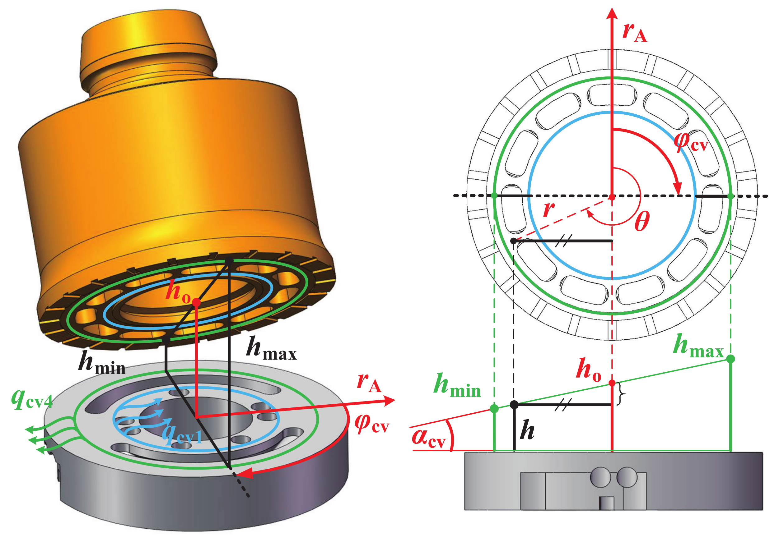
3.2. Viscous Wedge Geometric Model

Before modeling, the following assumptions should be stated: (1) The valve plate and the cylinder block are both rigid; (2) The oil film is an incompressible Newtonian fluid; (3) There is no turbulence and flow field curl in the oil film area and the cylinder block has no radial and axial movement; (4) The gravity of the oil film can be ignored; and (5) The centrifugal force and convective effect of the temperature difference, which are much smaller than the viscosity of the oil film, are not considered.
In order to facilitate the generation of finite element meshes in the oil film region, this paper adopts the analytical geometry method to model the oil film. Figure 3 shows the geometry of the oil film at the cylinder block/valve plate interface. R c v 1 and R c v 2 are the inner and outer radii of the inner sealing belt. R c v 3 and R c v 4 are the inner and outer radii of the outer sealing belt. R c v 5 and R c v 6 are the inner and outer radii of the auxiliary support belt.
The accuracy of the mesh will affect the calculation accuracy of the oil film’s load-bearing force. In finite element analysis, unstructured meshes that can discretize the target region more accurately are generally used to deal with discontinuous time-varying boundaries [32]. However, using unstructured meshes leads to remeshing of the oil film when the drive shaft rotates at any aperiodic angle, which greatly reduces the dynamic computational efficiency of the model [33]. Considering the calculation accuracy and efficiency comprehensively, this paper adopts an orthogonal structural mesh to divide the fluid region of the oil film in the cylindrical coordinate system.
As shown in Figure 3, the origin O A of the cylindrical coordinate system O A r A θ A z A is set as the center of the valve plate surface, and the z A axis is the driving axis of the cylinder block. The cylinder block rotates clockwise around the z A axis at an angular velocity ω and is subjected to moments from other components in the directions of θ A and r A , forming a wedge-shaped oil film (Figure 4) and turning the cylinder block over (Figure 5). In order to determine the geometry of the wedge-shaped oil film, at least three non-collinear feature points need to be selected. As shown in Figure 4, this paper selects three feature points P 1 ( R c v 4 , 0 , h 1 ), P 2 ( R c v 4 , 120 , h 2 ), and P 3 ( R c v 4 , 240 , h 3 ), which are independent of each other and spaced at 120 along the θ A direction. The n θ and n r meshes are uniformly set along the θ A and r A directions, respectively, as the boundaries of the geometric model.
The thickness of the oil film at the cylinder block/valve plate interface is calculated as
h = 2 h 1 h 2 h 3 3 R c v 4 r c o s θ + 3 ( h 2 h 3 ) 3 R c v 4 r s i n θ + h 1 + h 2 + h 3 3
where h is the thickness of the oil film mesh, r is the radius of the oil film mesh, and θ is the circumferential azimuth of the oil film mesh. h 1 , h 2 , and h 3 are the oil film thicknesses at P 1 , P 2 , and P 3 , respectively.
The change rates of the oil film thickness with time t and with the mesh circumferential azimuth θ are calculated as follows:
h t = r c o s θ 3 R c v 4 2 h 1 t h 2 t h 3 t + 3 r s i n θ 3 R c v 4 h 2 t h 3 t + 1 3 h 1 t + h 2 t + h 3 t
h θ = 3 ( h 2 h 3 ) 3 R c v 4 r c o s θ 2 h 1 h 2 h 3 3 R c v 4 r s i n θ
The radial and circumferential linear velocities of each mesh are calculated as
v r = 1 2 μ p r z 2 h 2 μ p r z
v θ = 1 2 μ r p θ z 2 h 2 μ r p θ ω r h z
where v r is the radial linear velocity, v θ is the circumferential linear velocity, μ is the dynamic viscosity of the oil, p is the pressure of the oil film mesh, z is the coordinate of the oil film in the direction of the z A axis, and ω is the angular velocity.
As shown in Figure 5, the overturning attitude of the cylinder block can be calculated by the oil film thickness at the center of the valve plate, the pitch angle, and the azimuth angle, as follows:
h = h o + r t a n α c v c o s ( θ φ c v )
where h o is the oil film thickness at the center of the valve plate (i.e., the average oil film thickness), α c v is the pitch angle, and φ c v is the azimuth angle.
Although either Equation (1) or (6) can be utilized to calculate the oil film thickness, Equation (1) does not need to calculate the derivative of the trigonometric function. In order to reduce the cumulative round-off error in the model calculation, Equation (1) is adopted in this paper.
The dimensionless Reynolds equation characterizing the lubricating characteristics of the cylinder block/valve plate interface can be simplified as
1 r ¯ r ¯ r ¯ h ¯ 3 p ¯ r ¯ + 1 2 π 2 1 r ¯ 2 θ ¯ h ¯ 3 p ¯ θ ¯ = 2 h ¯ t ¯ 1 2 π h ¯ θ ¯
r ¯ = r R c v 4 , θ ¯ = θ 2 π , h ¯ = 2 h h m a x + h m i n , p ¯ = p ( h m a x + h m i n ) 2 24 μ ω R c v 4 2 , t ¯ = ω t
where r ¯ , θ ¯ , h ¯ , p ¯ , and t ¯ are the normalized parameters of r, θ , h, p, and t, and h m a x and h m i n are the maximum and minimum oil film thicknesses, respectively.
The convergence criteria for solving Equation (7) are as follows:
Ω i , j p i , j k + 1 Ω i , j p i , j k Ω i , j p i , j k E R R p
where k is the number of iterations, Ω is the number of meshes in the oil film region, p i , j is the pressure of the ( i , j ) th mesh, and E R R p is the allowable error of the oil film pressure solution (set to 1 × 10 4 in this paper).
The parameter settings are shown in Table 1.

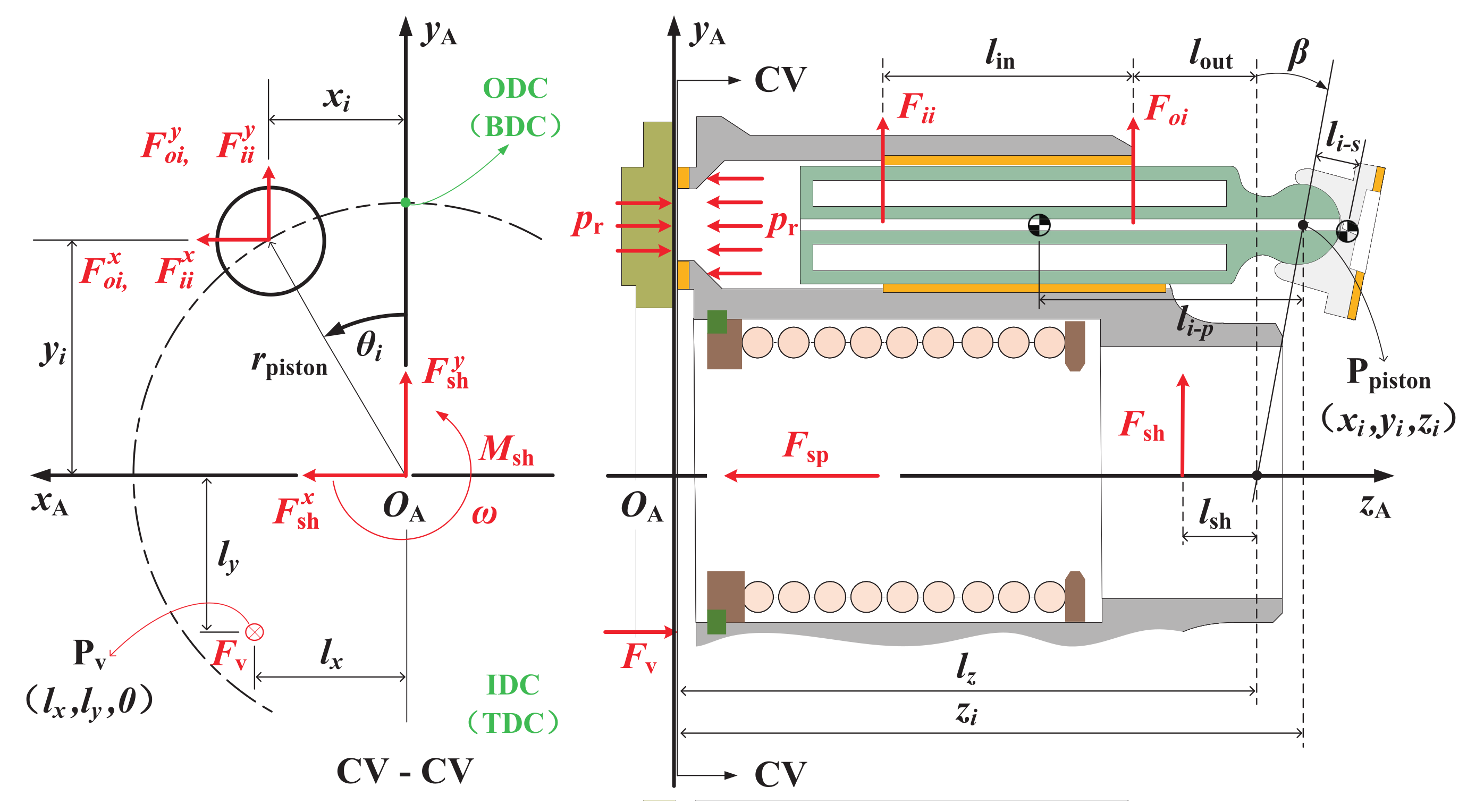
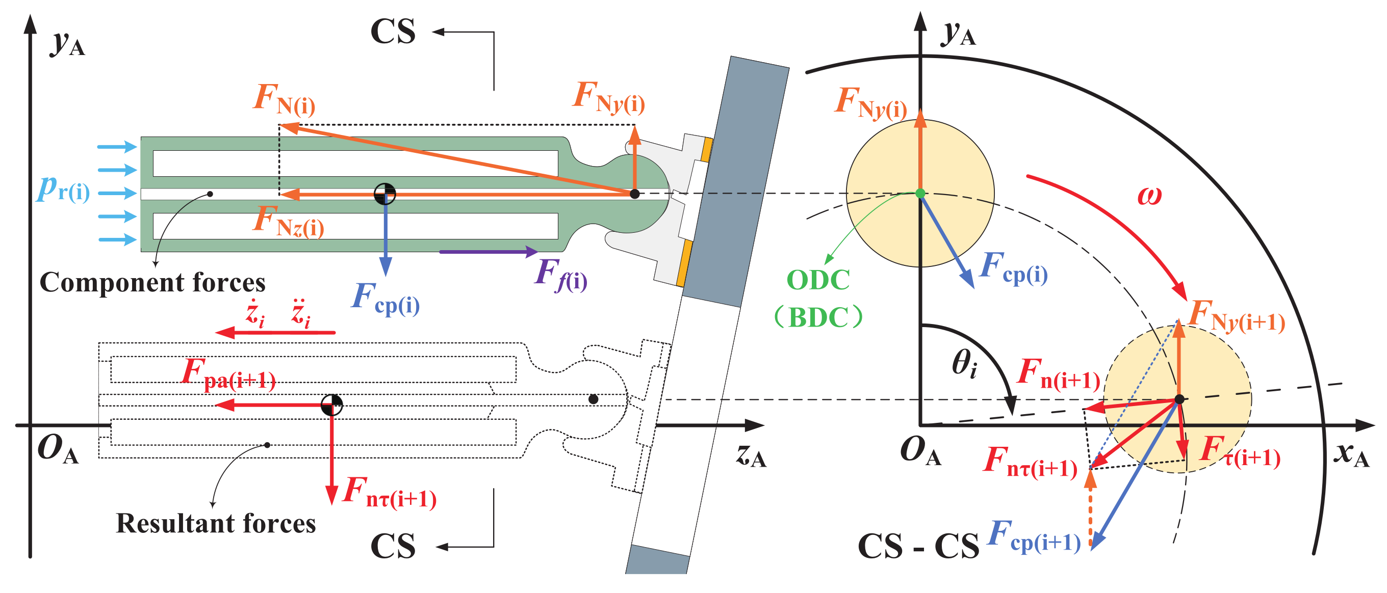
3.3. Multi-Body Dynamics Model

Before modeling, the following assumptions should be stated: (1) The valve plate, cylinder block, piston-slipper assembly, swash plate, and drive shaft are all rigid; (2) The friction between the piston and the cylinder block can be ignored; and (3) There is no metal-to-metal contact between the valve plate and the cylinder block.
The load-bearing force and anti-overturning moment of the oil film are obtained based on the equilibrium conditions of the cylinder block force and moment. The main sources of the non-oil film loads on the cylinder block are the oil in the piston chamber, cylinder block spring, drive shaft, and piston. The forces on the cylinder block are shown in Figure 6 and its three-dimensional Cartesian coordinate system is O A x A y A z A . The drive shaft drives the rotating components to rotate around the z A axis through splines. Due to the alternating action of the hold-down plate retainer, shoe hold-down plate, and shoe bearing plate, the piston-slipper assembly performs a linear reciprocating motion along the direction of the piston bore of the cylinder while rotating. The outer dead center (ODC) [34] is the position where the piston is farthest from the valve plate. When the piston is at the ODC, the volume of the piston chamber is the largest. The inner dead center (IDC) [34] is the position where the piston is closest to the valve plate. When the piston is at the IDC, the volume of the piston chamber is the smallest. The ODC (also known as the bottom dead center (BDC)) is set as the initial position of the cylinder block rotation. As the cylinder block rotates toward the IDC (also known as the top dead center (TDC)), the piston squeezes the closed chamber of the piston bore, increasing the oil pressure in the chamber and discharging the oil outward. As shown in Figure 6, the center point of the piston ball hinge is P p i s t o n ( x i , y i , z i ), the effective action area of a single piston is A p , the transient pressure of the piston chamber is p r ( θ i ), the preload force of the cylinder block spring is F s p , the overturning force on the cylinder block is F v , and its action point is P v ( l x , l y , 0). The inner and outer forces of the piston on the copper bushing of the piston bore are F i i and F o i . The force and moment of the drive shaft acting on the cylinder block are F s h and M s h , respectively. Among them, the direction of p r ( θ i ) is the negative direction of the z A axis; l z , l i n , l o u t , and l s h are fixed constants; and the directions of the other parameters are the positive direction of the coordinate system.
The force on the piston-slipper assembly is shown in Figure 7 and its three-dimensional Cartesian coordinate system is the same as that of the cylinder block (Figure 6). The reaction force of the swash plate on the slipper is F N , the reaction force of the cylinder block on the piston is F c p , and the friction force of the reciprocating motion of the piston is F f . The axial, circumferential, and radial resultant forces on the piston-slipper assembly are F p a , F τ , and F n , respectively. The resultant force of the circumferential and radial resultant forces on the piston-slipper assembly is F n τ . The directions of F N and F n are shown in Figure 7 and the directions of the other parameters are the positive direction of the coordinate system.
The center point displacement of the piston ball hinge is
x i = r p i s t o n s i n θ i
y i = r p i s t o n c o s θ i
z i = l z + r p i s t o n c o s θ i t a n β
where r p i s t o n is the piston pitch radius, θ i is the phase angle of the ith piston, l z is the position of the swash plate, and β is the maximum angle of the swash plate.
According to Figure 7, the reaction force of the swash plate on the slipper is calculated as
F N = A p p r ( m p + m s ) z i ¨ c o s β
where A p is the effective action area of a single piston, p r is the transient oil pressure in the piston chamber, m s is the mass of the slipper, and m p is the mass of the piston.
Next, in the directions of the x A axis and y A axis, the reaction forces of the cylinder block on the piston are F c p x and F c p y , respectively. They are calculated as
F c p x = ( m p + m s ) ω 2 x i
F c p y = 2 ( m p + m s ) z i ¨ s i n ( 2 β ) A p p r t a n β
According to the equilibrium conditions of the cylinder block force and moment, the inner and outer forces of the piston on the copper bushing of the piston bore are calculated as follows:
F i i x F i i y F o i x F o i y = 1 l i n ( z i l z + l o u t ) ( z i l z + l o u t ) + l i n [ F c p x F c p y ]
where l i n and l o u t are the effective lengths of the piston inside and outside the piston bore, respectively.
The overturning force F v and moment ( M c x and M c y ) on the cylinder block can be calculated by combining the transient pressure of each piston chamber, the force and moment of the drive shaft acting on the cylinder block, the preload force of the cylinder block spring, and the overturning force of the piston-slipper assembly
F v = i = 1 N p A p p r F s p
M c x = i = 1 N p [ A p p r r p i s t o n c o s θ i + A p p r t a n β ( l s h + r p i s t o n c o s θ i t a n β ) + 2 ( m p + m s ) s i n ( 2 β ) ω 2 r p i s t o n c o s θ i t a n β ( l z + r p i s t o n c o s θ i t a n β ) ]
M c y = i = 1 N p ω 2 ( m p + m s ) ( l z + r p i s t o n c o s θ i t a n β ) + A p p r r p i s t o n s i n θ i
where l s h is the position of the spline.
According to Equations (17)–(19), the coordinates of the equivalent action point of the overturning force on the cylinder block can be obtained:
( l x , l y , 0 ) = M c x F v , M c y F v , 0
where l x and l y are the distances from the equivalent action point of the overturning force to the y A axis and x A axis, respectively.

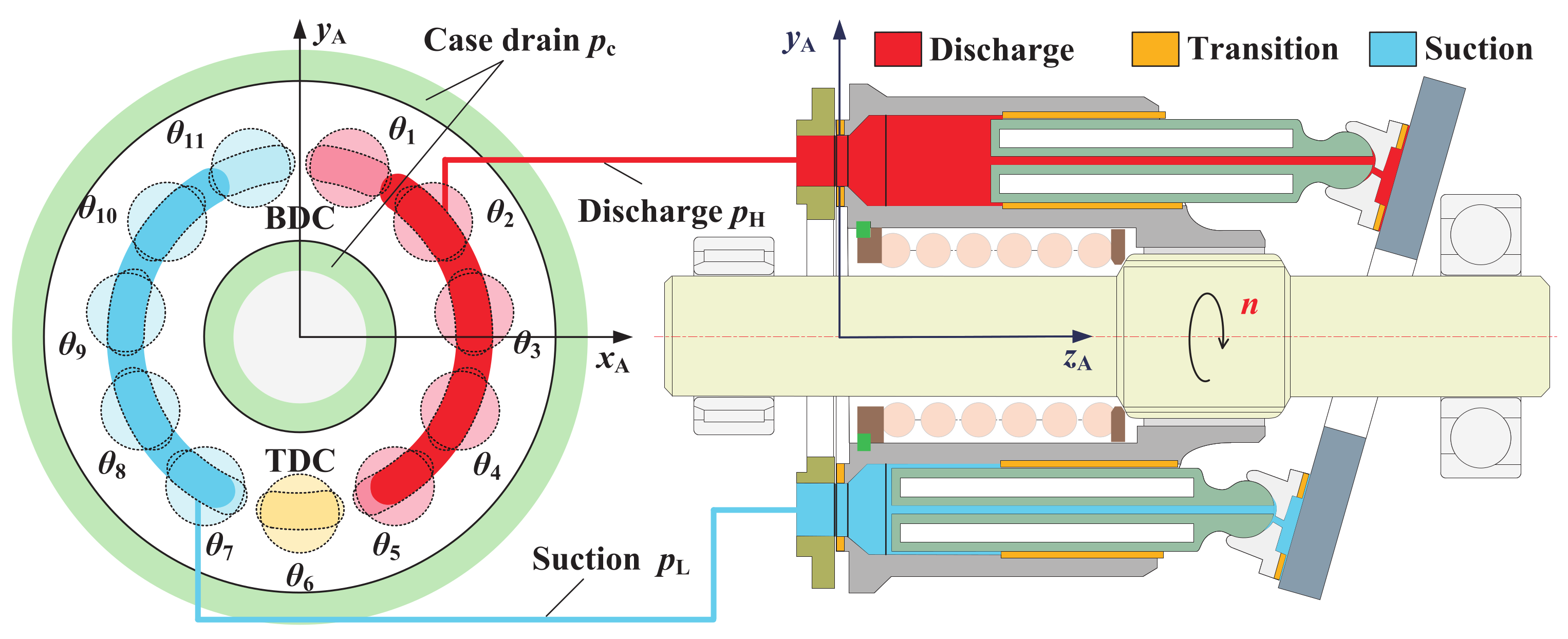
3.4. Non-Isothermal Full Oil Film Fluid Model

Before modeling, the following assumptions should be stated: (1) The oil film thickness does not change during the simulation process; (2) The oil is a Newtonian fluid; and (3) The angle of the swash plate and the rotational speed of the drive shaft remain constant.
As shown in Figure 8, the rotation and reciprocating motion of the piston cause periodic changes in the volume of the piston chamber V ( θ i ) , as does the transient pressure p r ( θ i ) in each piston chamber. The oil pressure of multiple piston chambers connected with the oil-suction and -discharge kidney grooves jointly determines the oil-suction and -discharge pressure of the piston pump, as well as the pulsation. The pressure boundary of the oil film at the cylinder block/valve plate interface is mainly composed of the oil-suction and -discharge kidney groove pressure, piston chamber transient pressure, and case drain pressure. The pressure boundary cannot be calculated using the multi-body dynamic model alone. In order to simplify the model calculation, existing studies usually simplify the p r ( θ i ) curve to different levels. Chen et al. [24] directly replaced the p r ( θ i ) curve containing high-frequency noise with a smooth curve. Huang et al. [35] replaced the p r ( θ i ) curve with the simplified pressure pulsation curve output from the lumped parameter model of the piston pump. Although the above research simplifies the calculation of the pressure boundary to some extent, it reduces accuracy. Since the CFD model can accurately simulate the heat transfer, swash plate vibration, oil suction [36], discharge damping characteristics [37], and cavitation in piston pumps [38,39,40], the pressure boundary can be calculated more accurately.
By establishing the non-isothermal full oil film CFD model of the APP, the p r ( θ i ) curve calculated using the CFD model is used as the pressure boundary of the dimensionless Reynolds equation for the first time. Specifically, the fluid domain model of the APP is first established, including the piston chamber, valve plate kidney groove, damping groove, slipper oil chamber, oil-suction and -discharge channels, and different lubricating interfaces, as shown in Figure 9a. Then, the fluid domain is meshed. The structured dynamic meshes are set up for active regions such as the piston chamber, slipper oil chamber, and lubricating interfaces. The binary tree method is used to quickly set up Cartesian meshes for stationary regions such as the oil-suction and -discharge channels, valve plate kidney grooves, and damping grooves. The fully implicit mismatched grid interface (MGI) technology automatically forms connections between the dynamic and static meshes. As shown in Figure 9b, the mesh size of the oil-suction and -discharge channels, valve plate kidney grooves, damping grooves, slipper chambers, and other regions is a maximum of 0.02 mm and a minimum of 0.001 mm. The surface mesh side length is 0.01 mm. Next, a standard k-epsilon turbulence model, fully cavitated cavitation model, and thermal radiation model are added. Parameters such as the fluid density, vaporization pressure, vapor density, dynamic viscosity, mass air content, oil-suction and -discharge pressure, and drain pressure are set and are shown in Table 1. The calculated pressure distribution of the fluid domain is shown in Figure 9c. Figure 9d shows the overall mesh diagram of the CFD model. Figure 9e,f shows the mesh diagrams of the suction and discharge channels, respectively. These two regions have complex structures with irregular and dense meshes. Figure 9g shows the mesh diagram of the piston chamber. The structure of this region is regular and the grid is also regular and low density. Figure 9h shows the mesh diagram of the ball clearance and slipper chamber. These two regions are small in size, with irregular and dense meshes.
The pressure boundary results calculated using the CFD model and the lumped parameter model are shown in Figure 10. The pressure in the oil-suction and -discharge channels, piston chamber transient pressure, and case drain pressure are indicated by different curves in Figure 10a. The variation in the transient pressure p r with the phase angle of the ith piston θ i is represented by a polar plot, as shown in Figure 10b. Under the combined action of the swash plate cross angle (i.e., secondary swash plate angle) and the kidney groove angle of the valve plate, there is a certain angle between the line of the ODC and IDC (i.e., red dashed line) and the center line of the valve plate (i.e., solid black line), which is called the indexing angle (i.e., indexing) and plays a role in the pre-compression and pre-decompression pressure. Before the piston kidney groove is connected to the discharge kidney groove, the transient pressure of the piston chamber is raised to 35 MPa, reducing the backfilling at the pump discharge port. Before the piston kidney groove is connected to the oil-suction kidney groove, the transient pressure of the piston chamber is reduced to 0.35 MPa, thereby reducing cavitation at the oil-suction channel.
Figure 10c,d shows the calculated p r ( θ i ) curves from the lumped parameter model and the CFD model, respectively. There are many similarities between the two curves. The pressure of the oil-suction kidney groove is about 0.35 MPa and the pressure of the oil-discharge kidney groove is about 35 MPa. The piston chamber’s transient pressure varies with the piston’s phase angle. When the piston is within the oil-suction kidney groove, its pressure curve coincides with the pressure curve of the oil-suction kidney groove. When the piston is within the oil-discharge kidney groove, its pressure curve coincides with the pressure curve of the oil-discharge kidney groove. When the piston is in the transition region, the transient pressure of the piston chamber shows a nonlinear upward or downward trend and the slope is large. However, the pressure pulsations of the two curves are different. For the p r ( θ i ) curve calculated using the lumped parameter model, when the oil-discharge kidney groove and the piston chamber are within the oil-discharge kidney groove, the pressure pulsation amplitude is about 1% and the pressure overshoot of the piston chamber caused by backfilling is about 0.5%. In contrast, for the p r ( θ i ) curve calculated using the CFD model, the pressure pulsation amplitude is about 12% and the pressure overshoot of the piston chamber caused by backfilling is about 20%. It can be seen that the CFD model is more accurate than the lumped parameter model in the calculation of dynamic characteristics such as pressure pulsation and overshoot. Using the calculation results of the CFD model as the pressure boundary of the oil film at the cylinder block/valve plate interface, the calculation of the characteristics of the oil film will be more accurate.
Combining the pressure boundary obtained in Figure 10 and the dynamic boundary (Equations (17)–(19)) calculated using the multi-body dynamics model, the overturning force and moment of the cylinder block are calculated and shown in Figure 11a. Figure 11b–d shows the polar plots of the overturning force F v and the moments ( M c x and M c y ) on the cylinder block as a function of the rotational angle of the drive shaft, respectively. The overturning force F v varies in the range of 34.5∼39 kN and the overturning moments M c x and M c y vary between 170 50 N·m and 820 790 N·m, respectively. Since the pistons are spaced evenly around the centerline of the cylinder block, the petal-shaped overturning force and moment curves have a variation period of 2 π / N p . The overturning moment of the cylinder block is mainly due to the pressure difference between the oil-suction and -discharge kidney grooves, inertial force, and centrifugal force of the piston-slipper assembly. When the APP operates under high-pressure and low-speed conditions, the influence of the pressure difference between the oil-suction and -discharge kidney grooves is dominant and the absolute value of M c y is much larger than that of M c x . When the APP operates under low-pressure and high-speed conditions, the influence of the inertial force and centrifugal force of the piston-slipper assembly is dominant and the absolute value of M c y is slightly larger than or even smaller than that of M c x .
The cylinder overturning forces and moments in Figure 11 are theoretical values calculated from the pressure and dynamic boundaries of the oil film at the cylinder block/valve plate interface. The pressure of the mesh of the oil film p i , j obtained by solving the dimensionless Reynolds equation is discrete. The discrete pressures are integrated according to Equations (21)–(23), and the anti-overturning force F z and moments M f x and M f y of the oil film can be further obtained based on the vicious wedge geometric model.
F z = 1 n r 1 n θ p i , j r i , j Δ r Δ θ
M f x = 1 n r 1 n θ p i , j r i , j 2 c o s θ i , j Δ r Δ θ
M f y = 1 n r 1 n θ p i , j r i , j 2 s i n θ i , j Δ r Δ θ
( E x , E y , 0 ) = M f y F z , M f x F z , 0
where n θ and n r are the number of meshes in the circumferential and radial directions of the oil film, respectively. p i , j , r i , j , and θ i , j are the pressure, radius, and radian of the ( i , j ) th oil film mesh. Δ r and Δ θ are the radial length and circumferential radian of the oil film mesh, respectively. E x and E y are the distances from the equivalent action point of the anti-overturning force to the y A and x A axes, respectively.
The dimensionless Reynolds equation (Equation (7)) considers the variation in oil film thickness. Under the same operating conditions with the same piston pump structure, the same drive shaft rotational angle, and different oil film thickness change rates, the oil film pressures at the cylinder block/valve plate interface obtained according to Equation (7) are different. Since the initial value of the oil film thickness change rate is artificially set before the model calculation, it is necessary to use the Newton–Raphson method to solve Equation (25) to obtain the correct oil film thickness change rate. Further, three pairs of forces or moments are made equal, namely the overturning force F v and anti-overturning force F z , the overturning moment M c x and anti-overturning moment M f x , and the overturning moment M c y and anti-overturning moment M f y .
EQ h 1 t , h 2 t , h 3 t = ( F z F v ) / F v ( M f x M c x ) / M c x ( M f y M c y ) / M c y = E Q F E Q x E Q y = 0
EQ = m a x E Q F , E Q x , E Q y E R R E Q
where E Q F is the axial force error of the oil film, E Q x is the moment error in the direction of the x A axis, E Q y is the moment error in the direction of the y A axis, EQ is the resultant vector composed of errors in all directions, and E R R E Q is the allowable error of the oil film force and moment solution (set to 1 × 10 2 in this paper).
The above describes the complete modeling process of the cylinder block/valve plate interface oil film model of the APP. Based on the established model, the oil film characteristics under different operating conditions (such as pressure, speed, displacement) and structures are studied in the next section.

4. Simulation Results and Analysis

4.1. Simulation Setup

Before the simulation analysis, a mesh independence test and oil film force balance error analysis should be carried out to determine the number of meshes and verify the accuracy of the oil film pressure calculation results, respectively.

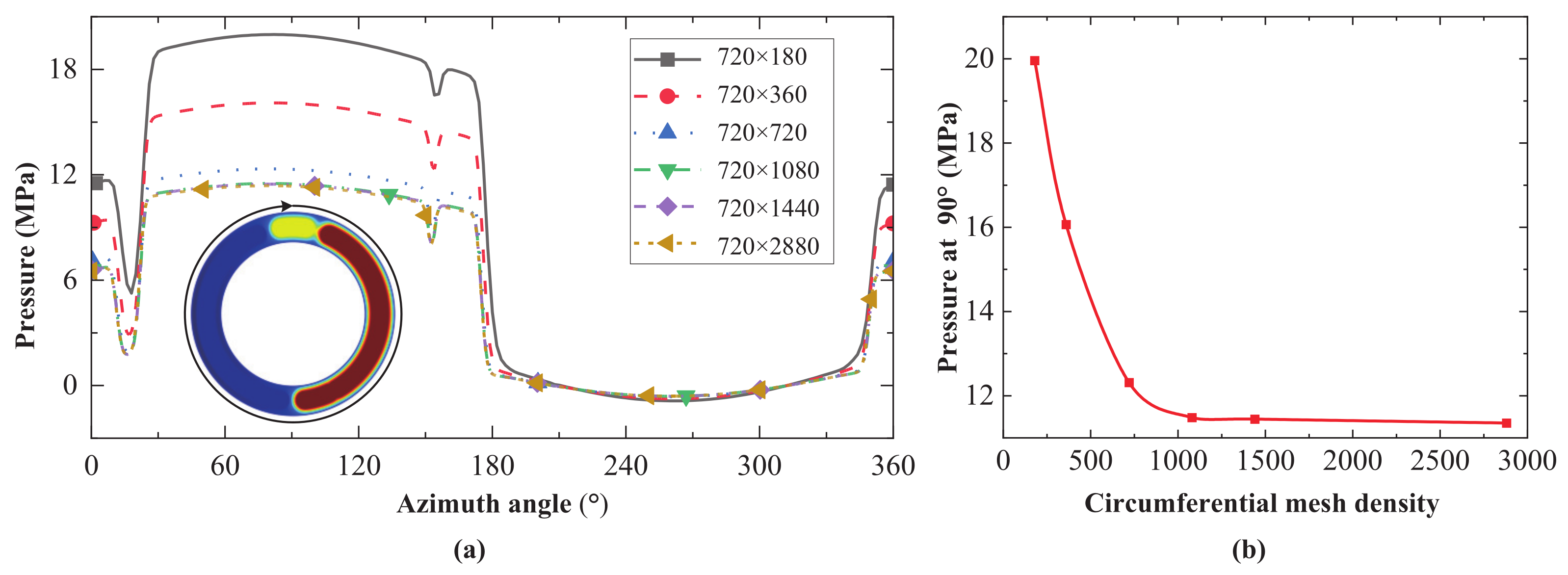
4.1.1. Mesh Independence Test

The calculation of the cylinder block/valve plate interface oil film model included the discrete solution of the elliptic partial differential equation. The total error between the partial differential equation’s exact solution and the discrete equation’s numerical solution consisted of the dispersion error and the rounding error, and there was a mutually restrictive relationship between the two errors. When the mesh density increased, the dispersion error decreased, the rounding error increased, and the computational efficiency decreased. When the mesh density decreased, the dispersion error increased, the rounding error decreased, and the computational efficiency increased. Therefore, under the premise of ensuring the accuracy of the model calculation results, it was necessary to verify the independence of the mesh to improve the calculation efficiency as much as possible. The mesh density was used as a variable during the independence test and gradually increased. The mesh was considered independent when the calculated pressure results no longer changed significantly. The specific steps are as follows: (1) Calculate the convergence result of the oil film pressure at a low mesh density; (2) Increase the mesh density to calculate the oil film pressure; and (3) Compare the calculation results of steps (1) and (2) to determine whether the oil film pressure difference is less than the threshold. If so, select the mesh density value used in step (1) as the final density value. If not, continue to increase the mesh density for calculation and comparison.
The mesh density settings for the oil film model included the radial and circumferential directions. To determine the radial and circumferential mesh densities, the pressures at different mesh densities were calculated, and the results are shown in Figure 12 and Figure 13.
After cross-comparison, it was found that when the number of radial meshes was 720, the requirement of mesh independence could be met. Therefore, the radial mesh number was set to 720. As shown in Figure 12, as the circumferential mesh density increased, the pressure changes at all mesh nodes in the circumference direction gradually decreased. The authors noticed that the mesh node pressure at the 90 phase varied most significantly with the circumferential mesh density so this mesh was chosen as a proxy for the independence test. The test results show that when the number of circumferential meshes is 1080, the mesh pressure tends to be stable (about 11.4 MPa). Therefore, the number of circumferential meshes in the oil film model is 1080.
Once the appropriate circumferential mesh density was determined, it was necessary to determine the appropriate radial mesh density. As shown in Figure 13, as the radial mesh density increased, the pressure changes at all mesh nodes in the radial direction gradually decreased. The authors noticed that the mesh node pressure at the radius of 29.6 mm varied most significantly with the radial mesh density so this mesh was chosen as a proxy for the independence test. The test results show that when the radial mesh number is 720, the mesh pressure tends to be stable (about 0.4 MPa). Therefore, the radial mesh number in the oil film model is 720.

4.1.2. Oil Film Force Balance Error Analysis

The Newton–Raphson method used in this paper is a mathematically common method for solving nonlinear algebraic equations. This method transforms the process of solving nonlinear equations into the process of repeatedly solving the corresponding linear equations, which introduces accumulated errors. As shown in Figure 14, when the cylinder block rotates to the 16th turn (the cumulative angle is 5580 ), the absolute value of the axial force error of the oil film satisfies E Q F 0.1 % , the absolute value of the moment error in the direction of the x A axis satisfies E Q x 1 % , and the absolute value of the moment error in the direction of the y A axis satisfies E Q y 0.05 % . All errors meet the model accuracy requirements.

4.2. Simulation Design

The characteristics of the oil film at the cylinder block/valve plate interface are the focus, as well as the challenges, of APP design. First, based on the oil film model established in Section 3, the pressure and thickness distribution of the oil film can be obtained through model calculation. The pressure and thickness are the basis for analyzing oil film characteristics such as lubricating, sealing, load bearing, and overturning. Therefore, in Section 4.3, the oil film pressure and thickness under pressures of 28 MPa and 35 MP are compared. The distribution law of the oil film pressure and thickness is summarized and the effects of the pressure increase on the oil film pressure and thickness distribution are analyzed.
Then, by substituting the oil film pressure and thickness into Equations (4) and (5), the radial and circumferential velocities of each oil film mesh can be further obtained, where the radial velocity is related to the leakage and the circumferential velocity is related to the viscous friction force/moment and friction coefficient. In Section 4.4, the viscous friction moment and friction coefficient of the cylinder block/valve plate interface are compared under pressures of 14∼42 MPa. The distribution law and extreme point orientation of the viscous friction moment are analyzed, the main factors that dominate the distribution of the viscous friction moment are revealed, and the regions that wear easily under high-pressure conditions are highlighted. In addition, by comparing the relationship between the friction coefficient and the oil film thickness under different pressures, the variation law and sensitive factors of the friction coefficient under a steady-state thickness are found.
Next, based on the radial velocities of the oil film at the radii R c v 1 and R c v 4 , the leakage flow rate can be further obtained to evaluate the sealing characteristic of the cylinder block/valve plate interface and the volumetric efficiency of the APP. In Section 4.5, under pressures of 14∼42 MPa, the variation law of the leakage is compared with the average thickness of the oil film. The characteristics of the leakage distribution on the circumference are summarized and the effect of the pressure increase on the leakage is analyzed. In addition, the volumetric efficiency of the APP is analyzed.
The axial load-bearing force is an indicator for measuring the oil film resistance to the load disturbance and the upper limit of the load-bearing capacity. In Section 4.6, under pressures of 14∼42 MPa, the variation law of the oil film thickness with the drive shaft rotational angle is revealed and the influence of the pressure increase on the oil film thickness is analyzed. The variation laws of the anti-overturning force action point under different operating conditions (such as pressure, rotational speed, and displacement) are compared and a method for optimizing the APP is provided.
Finally, in Section 4.7, under pressures of 14∼42 MPa, the variation laws of the overturning pitch of the cylinder block and azimuth angle are revealed. The reasons for the change in the cylinder block azimuth angle caused by the pressure increase are analyzed. The stages and areas where the cylinder block/valve plate interface may experience collision and wear are highlighted

4.3. Oil Film Pressure and Thickness

Based on the established cylinder block/valve plate interface oil film model, this paper compared the oil film pressure and thickness under pressures of 28 MPa and 35 MPa, as shown in Figure 15.
At a pressure of 35 MPa, the oil film pressure distribution changed periodically with the drive shaft rotational angle. In the first few cycles, the average value of the oil film pressure in the discharge region was large due to the significant pressure difference between the oil-suction and -discharge kidney grooves. Due to the squeeze effect of the gap flow and the cylinder block, the oil film pressure decreased logarithmically along the direction of the oil-suction and -discharge kidney grooves to the case. When the cylinder block was overturned, the sealing belt of the oil-suction kidney groove had negative pressure, and the larger the oil film radius, the greater the pressure on the edge of the oil film. Therefore, the periodic local high pressure in the sealing belt varied with the azimuth angle of the cylinder block. At 28 MPa, the oil film pressure distribution was similar to that at 35 MPa. However, due to the low pressure of the oil-discharge kidney groove, the mean and variance of the oil film pressure at 28 MPa were small, the azimuth angle of the cylinder body was small, and the local high pressure of the sealing belt was also reduced.
At a pressure of 35 MPa, the oil film thickness distribution changed periodically with the drive shaft rotational angle. During the first few cycles, the maximum, minimum, and average values of the oil film thickness gradually decreased and the average value gradually converged to 0.37 μ m. Due to the squeeze action of the wedge-shaped oil film, the maximum and minimum values of the oil film thickness always appeared in pairs in the sealing belt opposite the cylinder block/valve plate interface and the maximum value was more likely to appear on the side of the oil-discharge kidney groove. The line connecting the maximum and minimum points of the oil film thickness rotated counterclockwise and the rotational period was 4 π . The rotational speed was uneven throughout the cycle, starting slowly and ending quickly. At 28 MPa, the oil film thickness distribution was similar to that at 35 MPa. However, at 28 MPa, the pressure of the oil-discharge kidney groove was low, the cylinder block squeezed the oil film less, and the pressure difference between the suction and discharge kidney grooves was also small. Therefore, the average oil film thickness at 28 MPa was larger and the steady-state convergence value of the mean thickness was about 0.44 μ m. In addition, the steady-state convergence values of the oil film thickness at 14∼42 MPa were also calculated. Specifically, these values were about 0.68 μ m at 14 MPa, about 0.52 μ m at 21 MPa, and about 0.32 μ m at 42 MPa.

4.4. Lubricating Characteristics

The lubrication state of the oil film at the cylinder block/valve plate interface affects the torque efficiency of the APP, and the viscous friction moment and friction coefficient are essential indicators for characterizing the lubrication state. Based on the established oil film model, this paper compared the viscous friction moment and friction coefficient under pressures of 14, 21, 28, 35, and 42 MPa, as shown in Figure 16 and Figure 17.
The friction coefficient of the oil film is calculated as
f = 1 F v 1 n r 1 n θ μ v θ z r i , j Δ θ Δ r
Figure 16 shows a comparison of the viscous friction moment of the oil film at different pressures and the mesh color represents the magnitude of the viscous friction moment. At 35 MPa, the oil film viscous friction moment presented an eccentric elliptical ring pattern, which means that the viscous friction moment increased with the radius increase. However, the magnitudes were different in different directions. The maximum and minimum values of the viscous friction moment always occurred on the opposite side of the cylinder block/valve plate interface. Unlike the oil film thickness, when the maximum value of the viscous friction moment appeared on the outside of the outer sealing belt, its minimum value appeared on the inside of the opposite inner sealing belt. Under the dual action of the hydrodynamic effects and pressure difference, the maximum value of the viscous friction moment ( 25 × 10 4 N·m) appeared in the outer region near the upper-right corner of the oil-discharge kidney groove, whereas the minimum value ( 4.1 × 10 4 N·m) appeared in the inner region near the lower-left corner of the oil-suction kidney groove. At 14 MPa, 21 MPa, 28 MPa, and 42 MPa, the viscous friction moment distributions of the oil film were similar to that at 35 MPa. The difference is that the maximum and minimum values of the viscous friction moment increased with the increasing pressure and the pressure sensitivity decreased. At different pressures, the maximum and minimum values of the viscous friction moment were 13 × 10 4 N·m and 2.3 × 10 4 N·m at 14 MPa, 18 × 10 4 N·m and 3.1 × 10 4 N·m at 21 MPa, 22 × 10 4 N·m and 3.8 × 10 4 N·m at 28 MPa, and 27 × 10 4 N·m and 4.4 × 10 4 N·m at 42 MPa.
Figure 17 compares the friction coefficient and oil film thickness under different pressures. At 35 MPa, the friction coefficient decreased exponentially with increasing oil film thickness. The smaller the oil film thickness, the higher the sensitivity of the friction coefficient to thickness; conversely, it is lower. The steady-state convergence value of the oil film thickness at 35 MPa was about 0.37 μ m and the friction coefficient was about 0.033. At pressures of 14, 21, 28, and 42 MPa, the oil film friction coefficients were similar to that at 35 MPa. At different pressures, the friction coefficients corresponding to the steady-state oil film thickness were 0.053 at 14 MPa, 0.042 at 21 MPa, 0.037 at 28 MPa, and 0.031 at 42 MPa.
It should be noted that when the pressure is at 35 MPa or higher, there is a high probability that the lubrication state of the cylinder block/valve plate interface is mixed lubrication, especially before the run-in process is finished. At this time, asperity contacts potentially occur but were neglected in this study. Under high-pressure conditions, the pressure of the oil film is enough to cause micron-level deformation in the local area of the cylinder block copper plating, which will increase the local oil film thickness and decrease the local pressure. Since this study is based on the assumption that the cylinder block and valve plate are rigid, the influence of pressure deformation on the oil film characteristics was not considered.
To sum up, when the pressure of the APP increases, the friction coefficient and torque loss ratio become smaller. This conclusion is consistent with the torque efficiency measurement results of PV3 series APPs by the Eaton Company [41]: the higher the pressure, the higher the torque efficiency. For every 7 MPa increase in pressure, the torque efficiency increases by 1∼2%.

4.5. Sealing Characteristics

The sealing state of the cylinder block/valve plate interface affects the volumetric efficiency of the APP and leakage is one of the key indicators for characterizing the sealing state. Based on the established oil film model, the leakages at 14, 21, 28, 35, and 42 MPa were compared, as shown in Figure 18 and Figure 19.
Figure 18 compares the leakage and oil film thickness of the cylinder block/valve plate interface at different pressures. At 35 MPa, the leakage at the cylinder block/valve plate interface increased, fluctuating with the oil film thickness, and the average value of the leakage increased exponentially with the oil film thickness. The smaller the oil film thickness, the higher the fluctuation frequency and the smaller the leakage amplitude. When the steady-state convergence value of the oil film thickness was 0.37 μ m, the leakage was 0.095 mL/min. At 14, 21, 28, and 42 MPa, the leakages were similar to that at 35 MPa. Although the relationship between the leakage and pressure is complex in the local thickness range, the average leakage increased with the pressure. The leakages at different pressures were 0.125 mL/min at 14 MPa, 0.115 mL/min at 21 MPa, 0.105 mL/min at 28 MPa, and 0.085 mL/min at 42 MPa. Unlike the average leakage at the cylinder block/valve plate interface, the steady-state value of the leakage decreased with increasing pressure.
Next, this paper compared the leakage of the mesh nodes in the inner and outer sealing belts under different pressures and analyzed the leakage at different drive shaft rotational angles. Figure 19 and Figure 20 represent the leakage of the mesh nodes by the polar diameter of the polar coordinates and the nodes’ orientation by the phase. Note that the leakage to the case was positive and the leakage to the sealing belt was negative.
Figure 19 shows the total circumferential leakage of the cylinder block/valve plate interface at 35 MPa for drive shaft rotational angles of 0 and π . In order to facilitate comparative analysis, the leakages of the inner and outer sealing belts are presented as a graphic, as seen in Figure 19. It can be seen that the cylinder block/valve plate interface mainly leaked to the case in the oil-discharge kidney groove region (i.e., positive leakage) and absorbed oil from the case in the oil-suction kidney groove region (i.e., negative leakage). The positive leakage was much larger than the negative leakage. No matter where the drive shaft rotated, the absolute value of the outer sealing belt leakage was greater than that of the inner sealing belt, and the positive leakage of the oil-discharge kidney groove was much larger than that of the oil-suction kidney groove. According to the extreme points of the oil film thickness indicated in Figure 19, it can be seen that the positive and negative leakage extreme points occurred near the extreme points of the oil film thickness but they did not completely coincide. This is due to the circumferential rotation of the cylinder block and the centrifugal phenomenon of the oil. The maximum and minimum values of the outer sealing belt leakage were 1.97 × 10 7 L/min and 0.22 × 10 7 L/min, respectively. The maximum and minimum values of the inner sealing belt leakage were 1.37 × 10 7 L/min and 0.0088 × 10 7 L/min, respectively.
Figure 20 shows the total circumferential leakage of the cylinder block/valve plate interface when the drive shaft rotational angles were 0 and π . It can be seen that at 14, 21, 28, and 42 MPa, the total circumferential leakages were similar to that at 35 MPa. In Figure 20, it can be seen that the positive leakage decreased with increasing pressure, whereas the absolute value of negative leakage increased with increasing pressure. Among them, the maximum and minimum values of leakage around the outer sealing belt were 4.2 × 10 7 L/min and 0.76 × 10 7 L/min. The maximum and minimum values of leakage around the inner sealing belt were 2.8 × 10 7 L/min and 0.35 × 10 7 L/min. Both the maximum and minimum values mentioned above occurred at 14 MPa. At the same time, since the width of the inner sealing belt (2.35 mm) was smaller than that of the outer sealing belt (2.4 mm), the absolute value of the outer sealing belt leakage was always larger than that of the inner sealing belt.
Theoretically, an increase in pressure must lead to an increase in leakage. However, under the premise that the structure of the APP remains unchanged, the oil film thickness will decrease with the increase in pressure and the thickness decrease will lead to a leakage decrease. The model calculation results in this paper show that with the increase in pressure, the leakage decreased, indicating that the influence of the oil film thickness on the leakage was greater than that of the pressure. In addition, an increase in pressure resulted in an increase in volumetric loss. The volumetric loss consisted of the compression volumetric loss of the oil and the leakage volumetric loss of all lubricating interfaces. This paper only considered the leakage volumetric loss of the cylinder block/valve plate interface.
To sum up, when the pressure of the APP increases, the leakage becomes smaller and the volumetric loss becomes larger. This conclusion is consistent with the volumetric efficiency measurement results of PV3 series APPs by the Eaton Company [41]: the higher the pressure, the higher the volumetric efficiency. The volumetric efficiency will decrease by about 1% for every 7 MPa increase in pressure.

4.6. Load-Bearing Characteristics

When the cylinder block is pressed against the valve plate under the combined action of the piston chamber transient pressure, rotating component inertia force, and centrifugal force, the balance of the cylinder block needs to be maintained through the anti-overturning force and the moment generated by the oil film. Due to the viscous squeeze inside the oil film, it can provide the fixed anti-overturning force and moment and dynamically adapt to the overturning force and moment of the cylinder block. The load-adaptive capability of the oil film is the core of the cylinder block/valve plate interface design. Based on the established oil film model, the changing trends in the oil film thickness at pressures of 14, 21, 28, 35, and 42 MPa were compared, as shown in Figure 21. At the same time, the effects of the pressure, rotational speed, displacement, and piston number on the F z equivalent action point were also compared, as shown in Figure 22.
It can be seen in Figure 21 that at 35 MPa, the average thickness of the oil film decreased with the increase in the drive shaft rotational angle and the sensitivity of the oil film thickness to the drive shaft rotational angle decreased. At other pressures, the variation laws of the average oil film thickness with the drive shaft rotational angle were similar to that at 35 MPa and the average oil film thickness decreased with the pressure increase. On the one hand, the increase in pressure will lead to an increase in the overturning force of the cylinder block and the oil film is further squeezed, increasing the viscosity and stiffness while reducing the thickness and increasing the friction coefficient. On the other hand, since the increase in pressure will lead to a rise in the throttling leakage loss, reducing the oil film thickness is equivalent to reducing the throttling area and suppressing the leakage. It is worth noting that according to the results of the lubrication state in Section 4.3, it is also concluded that the higher the pressure, the larger the friction coefficient, which is consistent with the experimental results in the existing literature.
The F z action point trajectory is one of the key indicators for evaluating the degree of cylinder overturning. It is also a direct reflection of the oil film load-bearing capacity, which can be calculated using Equation (24). When designing the APP, its working conditions and structural parameters should be comprehensively considered to ensure that the F z action point trajectory is in the center area of the valve plate to prevent the cylinder from overturning. Figure 22 shows the F z action point trajectories of APPs with 5, 7, 9, and 11 pistons under different pressure, rotational speed, and swash plate inclination conditions.
As seen in Figure 22, the F z action point trajectory resembles a closed butterfly shape. The trajectory envelope decreased with the piston number and was offset with the pressure, rotational speed, and displacement. Due to the considerable pressure difference between the oil-suction and -discharge kidney grooves, the oil film was forced to form a moment in the y A axis direction and the trajectory deviated from the y A axis and was in the region of the positive half-axis of the x A axis. Figure 22 shows that the greater the number of pistons, the more concentrated the trajectory. When the number of pistons was five, the trajectory envelope was the largest, representing the most significant degree of cylinder overturning. When the number of pistons increased, the trajectory envelope and overturning degree of the cylinder block became smaller. When the piston number, rotational speed, and displacement were the same, the pressure was higher, the trajectory amplitude in the y A axis direction was smaller, and the trajectory was offset to the negative direction of the y A axis and the positive direction of the x A axis. When the piston number, pressure, and displacement were the same, the rotational speed was higher and the trajectory amplitude in the direction of the y A axis was smaller. At the same time, the trajectory was offset to the positive direction of the y A axis. When the piston number, pressure, and rotational speed were the same, the displacement was higher and the trajectory was offset more in the negative direction of the y A axis. Therefore, according to the above laws, the piston number, rotational speed, or displacement can be changed to prevent the cylinder block from overturning.
To sum up, when the pressure of the APP increases, the oil film thickness decreases. As the pressure, rotational speed, or displacement of the APP increase, the offset radius of the F z action point trajectory increases. As the number of pistons increases, the trajectory envelope shrinks. When the envelope or offset radius of the trajectory is too large, the cylinder block periodically overturns and the edge of the cylinder block/valve plate interface wears.

4.7. Overturning Characteristics

The overturning attitude of the cylinder block is one of the key pieces of information needed to accurately predict the lubricating, sealing, and load-bearing state of the oil film. Based on the established oil film model, this section compares the variation laws of the cylinder block pitch angle and azimuth angle under different pressures, as shown in Figure 23 and Figure 24.
The overturning azimuth angle of the cylinder block is calculated as
φ c v = a r c t a n 3 ( h 2 h 3 ) 2 h 1 h 2 h 3
The overturning pitch angle of the cylinder block is calculated as
α c v = a r c t a n h m a x h m i n 2 R c v 4
Figure 23 shows the variation in the cylinder block azimuth angle φ c v with the drive shaft rotational angle. At 35 MPa, φ c v changed periodically with the drive shaft rotational angle, with a range of 0 360 and a period of 4 π . The magnitude of φ c v changed rapidly as the drive shaft rotated to periodically alternating angles. The φ c v at 14, 21, 28, and 42 MPa was similar to that at 35 MPa. The ranges of φ c v at different pressures were 130 190 at 14 MPa, 110 230 at 21 MPa, 90 270 at 28 MPa, and 0 360 at 42 MPa. Combined with Figure 5, it can be seen that as the pressure decreased, the range of φ c v was greatly reduced, and φ c v always pointed to the transition area and slightly biased the oil-discharge kidney groove. The reason for this phenomenon is that when the pressure decreases, the overturning effect caused by the pressure difference between the oil-suction and -discharge kidney grooves gradually weakens, and the overturning effect caused by the inertial and centrifugal force of the rotating components gradually dominates. Therefore, it can be concluded that the overturning attitude of the cylinder block is volatile under high-pressure conditions. Since the cylinder block/valve plate interface is not in a state of pure fluid lubrication during the actual operation of the APP, the rapid change in φ c v during cycle alternation can easily cause the cylinder block and the valve plate to collide, resulting in the surface deflection and wear.
Figure 24 shows the variation in the cylinder block pitch angle α c v with the drive shaft rotational angle. At 35 MPa, α c v changed periodically with the drive shaft rotational angle, with a period of 4 π . When the drive shaft was rotated to periodically alternating angles, the value of α c v was approximately 0 . The maximum value of α c v always occurred in the middle of the cycle. At 14, 21, 28, and 42 MPa, the α c v was similar to that at 35 MPa. However, as the pressure increased, the periodic maximum value of α c v decreased gradually. Referring to Figure 23, it can be seen that when the APP operated under high-pressure conditions, the cylinder block was more likely to fall into periodic small-amplitude damped oscillations. This phenomenon was more obvious when the rotational speed was low and the displacement was large. In addition to low torque efficiency, this is one of the reasons why APPs generally do not operate at low rotational speeds. When the rotational speed is high, and the displacement is small, the cylinder block/valve plate interface will become more reliable due to the hydrodynamic effect.

4.8. Discussions

Based on the obtained oil film characteristics and laws of the cylinder block/valve plate interface, further suggestions for improving 35 MPa high-pressure APPs are proposed in terms of torque efficiency, volumetric efficiency, load-bearing capacity, and anti-overturning capacity, as follows:
(1)
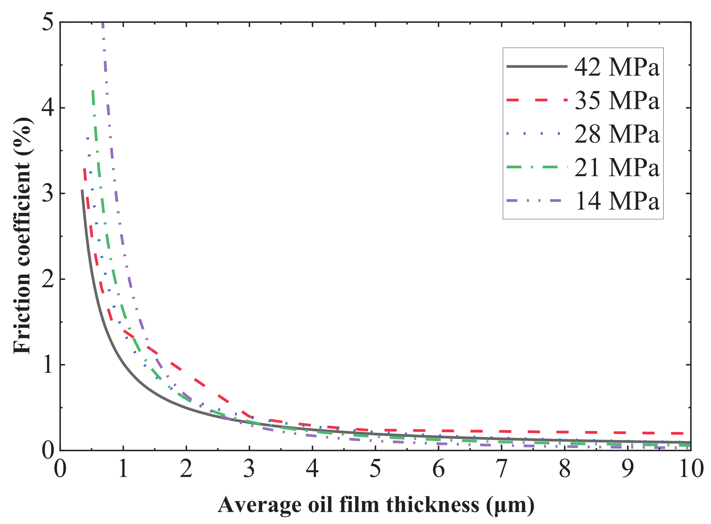
Figure 16 and Figure 17 show that at 35 MPa, the viscous friction moment of the outer sealing belt increases significantly and the lubricating characteristic decreases. The reason is that increased pressure increases the viscosity and cylinder block overturning force while reducing the oil film thickness and load-bearing area. In terms of structure, this paper proposes to increase the load-bearing area of the oil film by adding auxiliary support belts. In terms of operating conditions, this paper proposes to reduce the cylinder block overturning force by reducing the rotational speed and the viscosity by increasing the temperature. The above suggestions can optimize the lubrication state of the cylinder block/valve plate interface, reduce its viscous friction moment, and ease its wear. After adopting these suggestions, the edge wear of the valve plate will be significantly reduced at 35 MPa.
(2)
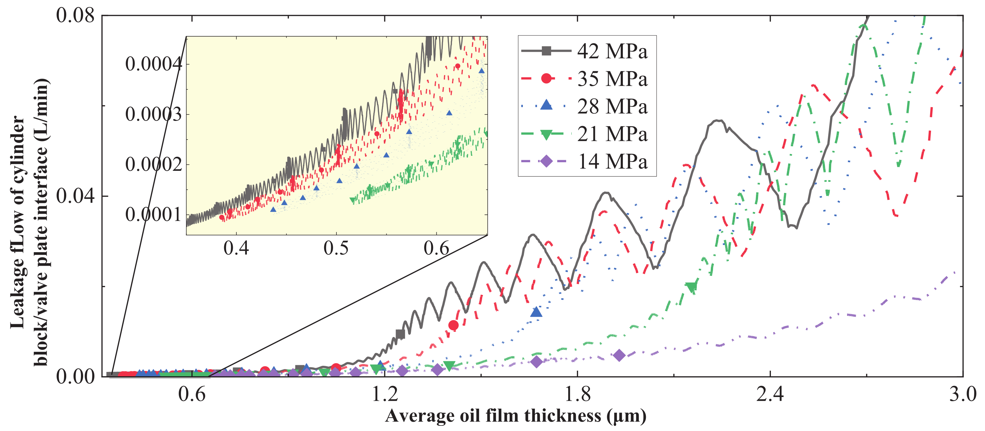
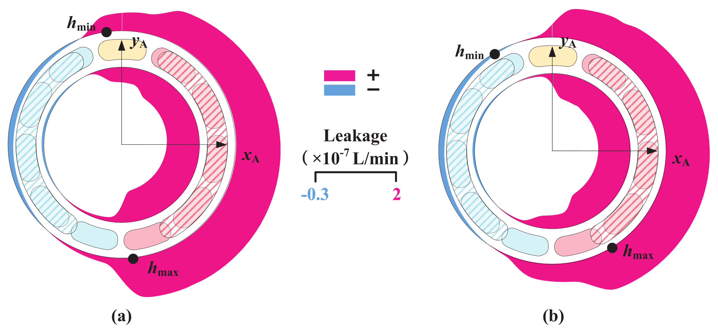
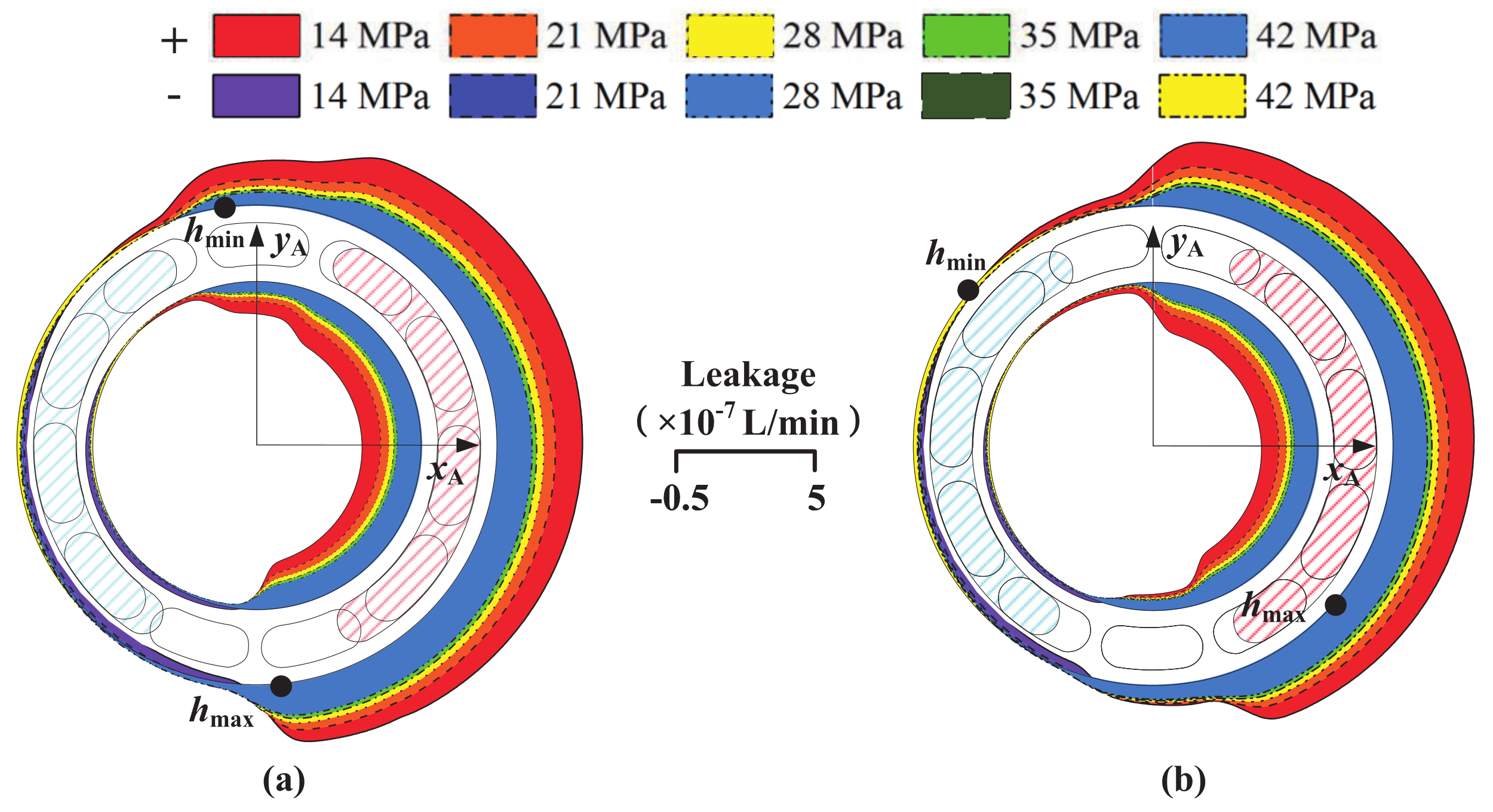
Figure 18, Figure 19 and Figure 20 show that at 35 MPa, the leakage of the cylinder block/valve plate interface increases significantly and the sealing characteristic decreases. The reason is that an increase in pressure increases the pressure difference between the oil-suction and -discharge kidney grooves and the case. In terms of structure, this paper proposes to appropriately increase the pre-compression length and stiffness of the cylinder block spring to increase the residual compression coefficient of the cylinder block/valve plate interface, thereby reducing the oil film thickness and leakage. After adopting these suggestions, the leakage of the cylinder block/valve plate interface will be reduced at 35 MPa.
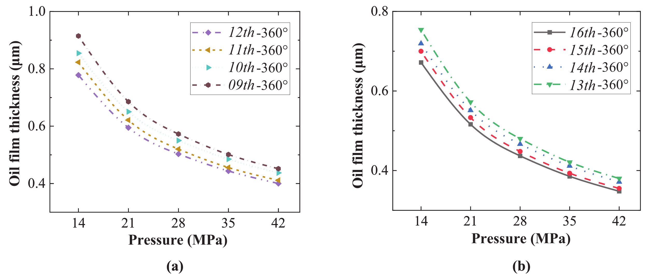
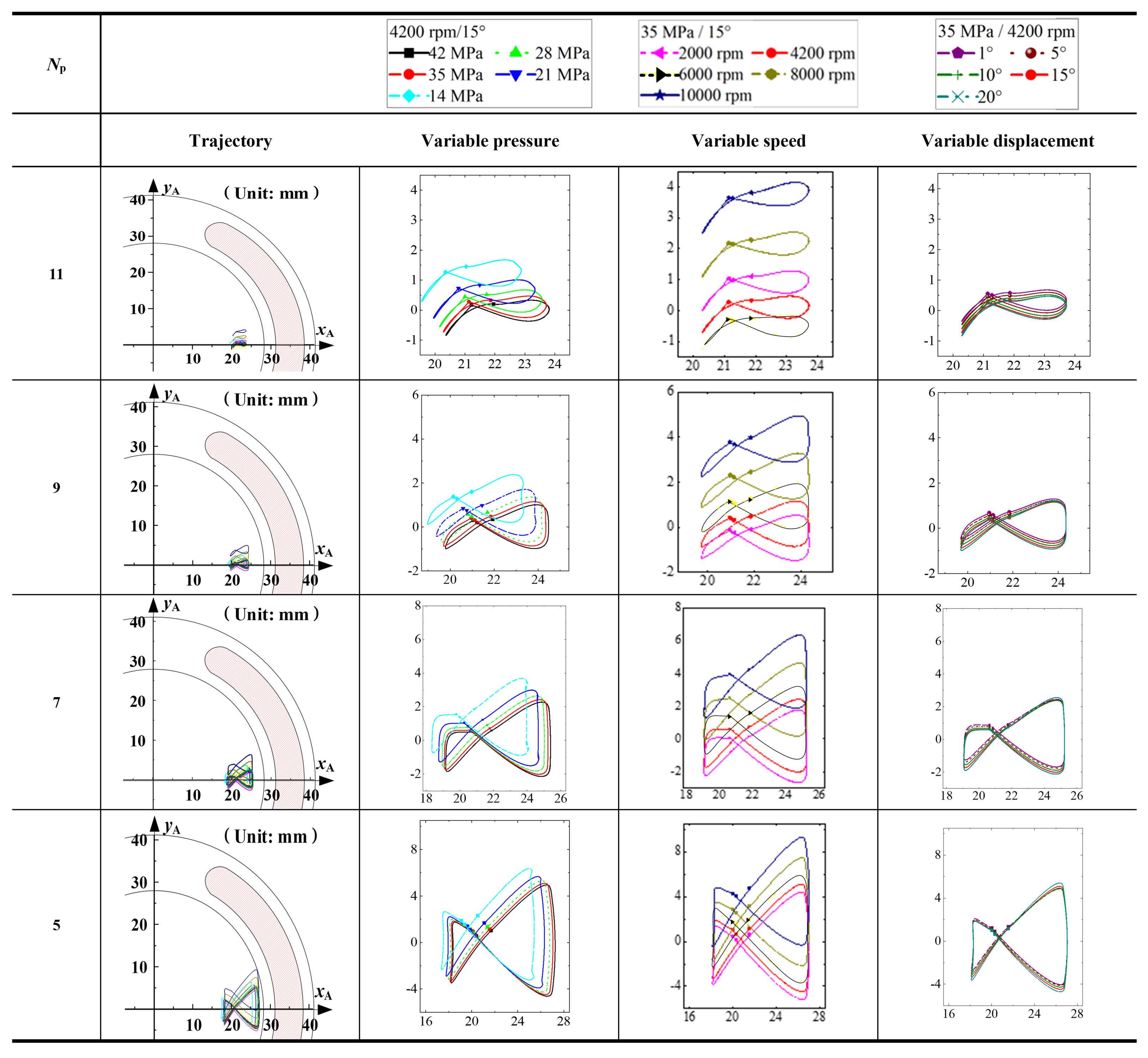
(3)
Figure 22 shows that at 35 MPa, the oil film thickness of the cylinder block/valve plate interface is significantly reduced, the anti-overturning force action point trajectory moves outward, and the load-bearing characteristic is greatly reduced. The reason is that the pressure increase will weaken the oil film hydrodynamic effect and increase the cylinder block overturning force. In terms of structure, an 11-piston layout is proposed in this paper to reduce the overturning force trajectory envelope of the cylinder block. In terms of operating conditions, this paper proposes to reduce the rotational speed and the swash plate inclination angle at zero displacement, which can enhance the hydrodynamic effect and load-bearing characteristic of the oil film while reducing the overturning force of the cylinder block. After adopting these suggestions, the anti-overturning force and load-bearing capacity of the cylinder block/valve plate interface will be increased at 35 MPa.
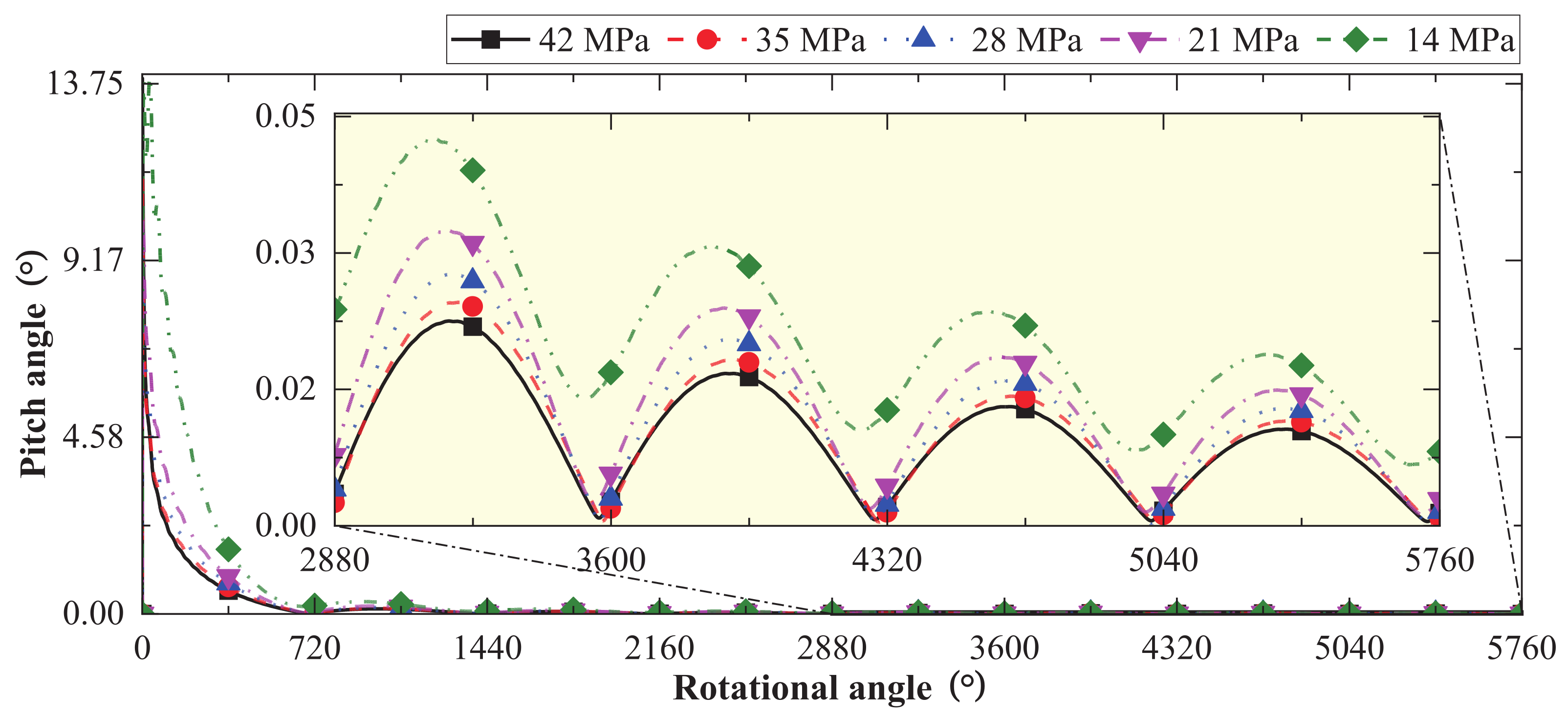
(4)
Figure 23 and Figure 24 show that at 35 MPa, the pitch angle and azimuth angle of the cylinder block both show severe periodic changes, resulting in easy edge collision and wear with the valve plate. The reason is that the pressure increase will aggravate the overturning behavior of the cylinder block in the axial and circumferential directions. In terms of structure, this paper proposes to adopt an external support cylinder configuration (that is, to add an extra bearing between the cylinder block and the case) to fix the cylinder circumferentially and optimize the force-bearing form of the drive shaft. This method can fundamentally eliminate the risk of collision between the cylinder block and the valve plate. After adopting these suggestions, the cylinder block will not overturn at 35 MPa.

5. Conclusions

In this paper, the cylinder block/valve plate interface of a 35 MPa high-pressure APP is taken as the research object. Firstly, an oil film model that can simultaneously analyze the characteristics of lubricating, sealing, load-bearing, and overturning is established. The model consists of a viscous wedge geometric model, multi-body dynamics model, and full oil film CFD model. The calculation accuracy of the oil film model is ensured through a mesh independence test and force balance error analysis. Then, parameters, such as oil film thickness and pressure, viscous friction moment, friction coefficient, leakage, overturning force action point trajectory, cylinder block pitch angle, and azimuth angle at different pressures are obtained through model calculations. The different characteristics of oil film are analyzed comprehensively and systematically, and the evolution laws of different characteristics with pressure changes are revealed. With the increase in the APP operating pressure, the friction coefficient and torque loss ratio of the cylinder block/valve plate interface will become smaller and the volumetric loss ratio will increase. At the same time, the F z action point trajectory will offset to the negative direction of the y A axis and the positive direction of the x A axis, which will aggravate the periodic overturning of the cylinder block and the wear of the valve plate. After that, suggestions are proposed to optimize the torque efficiency, volumetric efficiency, load-bearing capacity, and anti-overturning capacity of a 35 MPa high-pressure APP.

Author Contributions

Conceptualization, T.W., L.C., X.O. and S.G.; Data curation, T.W., X.Z. and Y.L.; Formal analysis, H.L.; Funding acquisition, X.O.; Investigation, T.W. and X.O.; Methodology, J.F., H.L., X.O. and S.G.; Project administration, H.L. and X.O.; Resources, J.F. and X.Z.; Software, Y.L.; Supervision, L.C. and S.G.; Validation, J.F.; Writing—original draft, T.W.; Writing—review and editing, H.L. All authors have read and agreed to the published version of the manuscript.

Funding

This research was funded by the National Natural Science Foundation of China (Grant No. 51890883 and U2141209), the Aviation Science Foundation of China Academy of Aeronautics (Grant No. 20182876003), and Project 1912.

Data Availability Statement

Not applicable.

Conflicts of Interest

The authors declare no conflict of interest. The funders had no role in the design of the study; in the collection, analyses, or interpretation of data; in the writing of the manuscript; or in the decision to publish the results.

Abbreviations

The following abbreviations are used in this manuscript:
APPAviation Piston Pump
CFDComputational Fluid Dynamics
MTBFMean Time Between Failure
CTDMACyclic Tridiagonal Matrix Algorithm
TDMATridiagonal Matrix Algorithm
ODCOuter Dead Center
BDCBottom Dead Center
IDCInner Dead Center
TDCTop Dead Center
Nomenclature
A p Effective action area of a single piston (m 2 )
E Q F Axial force error of the oil film (N)
E Q x Moment error in the direction of the x A axis (N·m)
E Q y Moment error in the direction of the y A axis (N·m)
EQ Resultant vector composed of errors in all directions (-)
E R R E Q Allowable error of the oil film force and moment solutions (-)
E R R p Allowable error of the oil film pressure solution (-)
E x , E y Distances from the anti-overturning force equivalent to the action point to y A / x A axes (m)
fFriction coefficient (-)
F c p Reaction force of the cylinder block to the piston (N)
F c p x , F c p y Reaction forces of the cylinder block to the piston in the directions of the x A / y A axes (N)
F f Friction force of the piston reciprocating motion (N)
F i i , F o i Inner/outer forces of the piston on the copper bushing of the piston bore (N)
F N Reaction force of the swash plate to the slipper (N)
F n τ Resultant force of the circumferential and radial resultant forces on the piston-slipper assembly (N)
F o i x , F o i y Outer forces of the piston on the copper bushing of the piston bore in the directions of the x A / y A axes (N)
F p a , F τ , and F n Axial/circumferential/radial resultant forces on the piston-slipper assembly (N)
F s h , M s h Force/moment of the drive shaft on the cylinder block (N)/(N·m)
F s h x , F s h y Forces of the drive shaft on the cylinder block in the directions of the x A / y A axes (N)
F s p Preload force of the cylinder block spring (N)
F v Overturning force on the cylinder block (N)
F z Anti-overturning force (N)
hThickness of the oil film mesh (m)
h m i n , h m a x Minimum/maximum oil film thicknesses (m)
h o Oil film thickness at the valve plate center (m)
h 1 , h 2 , and h 3 Oil film thicknesses at points P 1 , P 2 , and P 3 (m)
kNumber of iterations (-)
l i n , l o u t Effective lengths of the piston inside/outside the piston bore (m)
l s h Position of the spline (m)
l x , l y Distances from the overturning force equivalent action point to the y A / x A axes (m)
l z Position of the swash plate (m)
M c x , M c y Overturning moments on the cylinder block in the directions of the x A / y A axes (N·m)
M f x , M f y Anti-overturning moments in the direction of x A / y A (N·m)
m p Mass of the piston (kg)
m s Mass of the slipper (kg)
nRotational speed (rev/min)
N p Number of pistons (-)
n θ , n r Number of meshes in the circumferential/radial directions of the oil film (-)
pPressure of the oil film mesh (Pa)
p H , p L , p c Discharge/suction/drain pressure (Pa)
p r Transient pressure in the piston chamber (Pa)
q c v 1 , q c v 4 Leakages of inner/outer sealing belt (L/min)
rRadius of the oil film mesh (m)
r p Radius of the piston (m)
r p i s t o n Piston pitch radius (m)
R c v 1 , R c v 2 Inner/outer radii of the inner sealing belt (m)
R c v 3 , R c v 4 Inner/outer radii of the outer sealing belt (m)
R c v 5 , R c v 6 Inner/outer radii of the auxiliary support belt (m)
tTime (s)
VPiston chamber volume (m 3 )
v r , v θ Radial/circumferential linear velocities (m/s)
x i , y i , and z i Center point displacements of the piston ball hinge in the direction of x A / y A / z A (m)
zCoordinate of the oil film in the direction of the z A axis (m)
z ˙ i , z ¨ i Piston velocity/acceleration in the direction of the z A axis (m/s)/(m/s 2 )
α c v Pitch angle (rad)
β Maximum angle of the swash plate ( )
θ Circumferential azimuth of the oil film mesh (rad)
ω Angular velocity (rad/s)
μ Dynamic viscosity of the oil (Pa·s)
ρ Fluid density (kg/m 3 )
φ c v Azimuth angle (rad)
Δ r , Δ θ Radial length/circumferential radian of the oil film mesh (m)
θ i Phase angle of the ith piston (rad)
Ω Number of meshes in the oil film region (-)

References

  1. Moir, I.; Seabridge, A. Aircraft Systems: Mechanical, Electrical, and Avionics Subsystems Integration, 3rd ed.; Wiley: Chichester, UK, 2008. [Google Scholar]
  2. Li, L.; Lee, K.; Ouyang, X.; Yang, H. Analytical harmonic method for modeling high-frequency oscillation with applications to aircraft piston pump vibration analysis. IEEE/ASME Trans. Mechatron. 2021, 26, 918–929. [Google Scholar] [CrossRef]
  3. Chao, Q.; Zhang, J.; Xu, B.; Huang, H.; Pan, M. A review of high-speed electro-hydrostatic actuator pumps in aerospace applications: Challenges and solutions. J. Mech. Des. 2019, 141, 050801. [Google Scholar] [CrossRef] [Green Version]
  4. Guo, S.; Chen, J.; Lu, Y.; Wang, Y.; Dong, H. Hydraulic piston pump in civil aircraft: Current status, future directions and critical technologies. Chin. J. Aeronaut. 2020, 33, 16–30. [Google Scholar] [CrossRef]
  5. Collin, P.; Malec, D.; Lefevre, Y. A general method to compute the electric flux lines between two magnet wires in close contact and its application for the evaluation of partial discharge risks in the slots of electric machines embedded in future transportation systems. Adv. Aerosp. Sci. Technol. 2021, 6, 24–42. [Google Scholar] [CrossRef]
  6. Zhao, J.; Fu, Y.; Ma, J.; Fu, J.; Chao, Q.; Wang, Y. Review of cylinder block/valve plate interface in axial piston pumps: Theoretical models, experimental investigations, and optimal design. Chin. J. Aeronaut. 2021, 34, 111–134. [Google Scholar] [CrossRef]
  7. Chao, Q. Derivation of the Reynolds equation in cylindrical coordinates applicable to the slipper/swash plate interface in axial piston pumps. Proc. Inst. Mech. Eng. Part J.-J. Eng. Tribol. 2021, 235, 798–807. [Google Scholar] [CrossRef]
  8. Zhao, J.; Fu, Y.; Wang, M.; Fu, J.; Chao, Q.; Wang, S.; Deng, M. Experimental research on tribological characteristics of TiAlN coated valve plate in electro-hydrostatic actuator pumps. Tribol. Int. 2021, 155, 106782. [Google Scholar] [CrossRef]
  9. Zhang, J.; Lyu, F.; Xu, B.; Huang, W.; Wu, W.; Guo, Z.; Xu, H.; Huang, X. Simulation and experimental investigation on low wear rate surface contour of piston/cylinder pair in an axial piston pump. Tribol. Int. 2021, 162, 107127. [Google Scholar] [CrossRef]
  10. Fagg, A. Fluid film lubrication of parallel thrust surfaces. Proc. Inst. Mech. Eng. 1946, 155, 49–67. [Google Scholar] [CrossRef]
  11. Mckeown, J.; Milner, D.; Shute, N.; Turnbull, D. Hydrodynamic factors affecting the design of valve plates and thrust bearings. Proc. Inst. Mech. Eng. 1966, 181, 653–666. [Google Scholar] [CrossRef]
  12. Manring, N. Tipping the cylinder block of an axial-piston swash-plate type hydrostatic machine. J. Dyn. Sys., Meas. Control 2000, 122, 216–221. [Google Scholar] [CrossRef]
  13. Yamaguchi, A. Formation of a fluid film between a valve plate and a cylinder block of piston pumps and motors: 1st report, a valve plate with hydrodynamic pads. Bull. JSME 1986, 29, 1494–1498. [Google Scholar] [CrossRef]
  14. Yamaguchi, A.; Sekine, H. Formation of a fluid film between a valve plate and a cylinder block of piston pumps and motors: 3rd report, fluid film sluctuation and loss power. Trans. Jpn. Soc. Mech. Eng. Part B 1989, 55, 427–433. [Google Scholar] [CrossRef] [Green Version]
  15. Bergada, J.; Watton, J.; Kumar, S. Pressure, flow, force, and torque between the barrel and port plate in an axial piston pump. J. Dyn. Syst. Meas. Control 2008, 130, 011011. [Google Scholar] [CrossRef]
  16. Wieczorek, U.; Ivantysynova, M. Computer aided optimization of bearing and sealing gaps in hydrostatic machines—The simulation tool CASPAR. Int. J. Fluid Power 2002, 3, 7–20. [Google Scholar] [CrossRef]
  17. Wang, Z.; Hu, S.; Ji, H.; Wang, Z.; Liu, X. Analysis of lubricating characteristics of valve plate pair of a piston pump. Tribol. Int. 2018, 126, 49–64. [Google Scholar] [CrossRef]
  18. Jiang, J.; Yan, W.; Li, G. Analysis on micro-motion of cylinder block based on elasto-hydrodynamic lubrication. Ind. Lubr. Tribol. 2019, 72, 645–650. [Google Scholar] [CrossRef]
  19. Ivantysynova, M.; Huang, C. Investigation of the gap flow in displacement machines considering elastohydrodynamic effect. Proc. JFPS Int. Symp. Fluid Power 2002, 2002, 219–229. [Google Scholar] [CrossRef]
  20. Ivantysynova, M.; Baker, J. Power Losses in the Lubricating Gap Between Cylinder Block and Valve Plate of Swash Plate Type Axial Piston Machines. Int. J. Fluid Power 2009, 10, 29–43. [Google Scholar] [CrossRef]
  21. Huang, C.; Ivantysynova, M. A new approach to predict the load carrying ability of the gap between valve plate and cylinder block. In Proceedings of the Bath Workshop of Power Transmission and Motion Control, Bath, UK, 24 September 2003. [Google Scholar]
  22. Lv, Q.; Wang, D.; E, S.; Chen, H.; Hu, B. Study on the effects of the textured surface to improve the performance of cylinder block/valve plate interfaces. AIP Adv. 2019, 9, 45128. [Google Scholar] [CrossRef]
  23. Wang, Z.; Hu, S.; Zhang, H.; Ji, H.; Yang, J.; Liang, W. Effect of surface texturing parameters on the lubrication characteristics of an axial piston pump valve plate. Lubricants 2018, 6, 49. [Google Scholar] [CrossRef] [Green Version]
  24. Chen, Y.; Zhang, J.; Xu, B.; Chao, Q.; Liu, G. Multi-objective optimization of micron-scale surface textures for the cylinder/valve plate interface in axial piston pumps. Tribol. Int. 2019, 138, 316–329. [Google Scholar] [CrossRef]
  25. Li, Y.; Ji, Z.; Yang, L.; Zhang, P.; Xu, B.; Zhang, J. Thermal-fluid-structure coupling analysis for valve plate friction pair of axial piston pump in electro-hydrostatic actuator(EHA) of aircraft. Appl. Math. Model. 2017, 47, 839–858. [Google Scholar] [CrossRef]
  26. Ivantysyn, R.; Shorbagy, A.; Weber, J. Analysis of the Run-in Behavior of Axial Piston Pumps. In Proceedings of the Global Fluid Power Society PhD Symposium, Samara, Russia, 18–20 July 2018. [Google Scholar]
  27. Chacon, R.; Ivantysynova, M. Thermal effects on the fluid film in the cylinder block/valve plate interface due to compression and expansion of the fluid. JFPS Int. J. Fluid Power Syst. 2019, 11, 136–142. [Google Scholar] [CrossRef] [Green Version]
  28. Wang, S.; Tomovic, M.; Liu, H. Commercial Aircraft Hydraulic Systems: Shanghai Jiao Tong University Press Aerospace Series, 1st ed.; Elsevier: Waltham, MA, USA, 2015. [Google Scholar]
  29. Sharoni, A.; Etsion, I. Performance of end-face seals with diametral tilt and coning-hydrodynamic effects. ASLE Trans. 1981, 24, 61–70. [Google Scholar] [CrossRef]
  30. Kelkar, K.; Choudhury, D.; Minkowycz, W. Numerical method for the computation of flow in irregular domains that exhibit geometric periodicity using nonstaggered grids. Numer. Heat Transf. Part B 1997, 31, 1–21. [Google Scholar] [CrossRef]
  31. Aziz, K.; Settari, A. Petroleum Reservoir Simulation, 1st ed.; Applied Science Publishers: London, UK, 1979. [Google Scholar]
  32. Zecchi, M. A Novel Fluid Structure Interaction and Thermal Model to Predict the Cylinder Block/Valve Plate Interface Performance in Swash Plate Type Axial Piston Machines. Ph.D. Thesis, Purdue University, West Lafayette, IN, USA, November 2013. [Google Scholar]
  33. Richardson, D. Hydrodynamic Lubrication of Floating Valve Plate in An Axial Piston Pump. Ph.D. Thesis, Purdue University, West Lafayette, IN, USA, May 2019. [Google Scholar]
  34. Zhao, J.; Fu, J.; Li, Y.; Qi, H.; Wang, Y.; Fu, Y. Flow characteristics of integrated motor-pump assembly with phosphate ester medium for aerospace electro-hydrostatic actuators. Chin. J. Aeronaut 2022, in press. [Google Scholar] [CrossRef]
  35. Huang, X.; Xu, B.; Huang, W.; Xu, H.; Lyu, F.; Su, Q. Active pressure ripple reduction of a self-supplied variable displacement pump with notch least mean square filter. Micromachines 2021, 12, 932. [Google Scholar] [CrossRef]
  36. Dong, H.; He, Y.; Wang, Y.; Kou, G. Numerical investigation of effect of a centrifugal boost impeller on suction performance of an aircraft hydraulic pump. Chin. J. Aeronaut. 2022, 35, 236–248. [Google Scholar] [CrossRef]
  37. Zhang, B.; Zhao, C.; Hong, H.; Cheng, G.; Yang, H.; Feng, S.; Zhai, J.; Xiao, W. Optimization of the outlet unloading structure to prevent gaseous cavitation in a high-pressure axial piston pump. Proc. Inst. Mech. Eng. Part C J. Eng. Mech. Eng. Sci. 2022, 236, 3459–3473. [Google Scholar] [CrossRef]
  38. Xia, S.; Xia, Y.; Xiang, J.; Kou, G. Modeling and fault detection for specific cavitation damage based on the discharge pressure of axial piston pumps. Mathematics 2022, 10, 2461. [Google Scholar] [CrossRef]
  39. Chao, Q.; Wei, X.; Lei, J.; Tao, J.; Liu, C. Improving accuracy of cavitation severity recognition in axial piston pumps by denoising time–frequency images. Meas. Sci. Technol. 2022, 33, 055116. [Google Scholar] [CrossRef]
  40. Chao, Q.; Xu, Z.; Tao, J.; Liu, C. Capped piston: A promising design to reduce compressibility effects, pressure ripple and cavitation for high-speed and high-pressure axial piston pumps. Alex. Eng. J. 2023, 62, 509–521. [Google Scholar] [CrossRef]
  41. A Descriptive Summary of Vickers Inline Pumps and Their Applications. Available online: https://1library.net/document/zlvdm5oy-descriptive-summary-vickers-inline-pumps-applications.html (accessed on 4 December 2022).
Figure 1. Structure of the APP.
Machines 10 01196 g001
Figure 2. Geometry of the oil film.
Machines 10 01196 g002
Figure 3. The calculation flow of the oil film model.
Machines 10 01196 g003
Figure 4. The coordinate system and meshes of the oil film. (a) The coordinate system. (b) The meshes.
Machines 10 01196 g004
Figure 5. Overturning of the cylinder block.
Machines 10 01196 g005
Figure 6. Forces on the cylinder block.
Machines 10 01196 g006
Figure 7. Forces on the piston-slipper assembly.
Machines 10 01196 g007
Figure 8. Pressure boundary of the oil film.
Machines 10 01196 g008
Figure 9. Full oil film CFD model of the APP. (a) Fluid domain. (b) Mesh division. (c) Pressure clouds. (d) Overall mesh diagram. (e) Suction channel. (f) Discharge channel. (g) Piston chamber. (h) Ball clearance and slipper chamber.
Machines 10 01196 g009
Figure 10. Comparison of p r ( θ i ) curves. (a) Pressure boundary. (b) Indexing angle. (c) p r ( θ i ) curves from the lumped parameter model. (d) p r ( θ i ) curves from the CFD model.
Machines 10 01196 g010
Figure 11. Overturning force and moments on the cylinder block. (a) Overturning force and moments. (b) Overturning force curve. (c) The moment curve in the x A axis direction. (d) The moment curve in the y A axis direction.
Machines 10 01196 g011
Figure 12. Mesh independence test results of the circumferential mesh. (a) Variation in circumferential pressure with mesh density. (b) Mesh pressures at the 90 phase.
Machines 10 01196 g012
Figure 13. Mesh independence test results of the radial mesh. (a) Variation in radial pressure with mesh density. (b) Mesh pressures at the radius of 29.6 mm.
Machines 10 01196 g013
Figure 14. Oil film force balance error test results. (a) Oil film axial force error. (b) Moment error in the direction of the x A axis. (c) Moment error in the direction of the y A axis.
Machines 10 01196 g014
Figure 15. Oil film pressure and thickness results.
Machines 10 01196 g015
Figure 16. Viscous friction moment at different pressures. (a) Maximum friction moment at different pressures. (b) Minimum friction moment at different pressures.
Machines 10 01196 g016
Figure 17. The relationship between the oil film thickness and friction coefficient.
Machines 10 01196 g017
Figure 18. The relationship between oil film thickness and leakage.
Machines 10 01196 g018
Figure 19. Leakage at 35 MPa. (a) θ = 0 . (b) θ = π .
Machines 10 01196 g019
Figure 20. Leakage at different pressures. (a) θ = 0 . (b) θ = π .
Machines 10 01196 g020
Figure 21. Variation in oil film thickness with pressure. (a) 9th∼12th circles. (b) 13th∼16th circles.
Machines 10 01196 g021
Figure 22. F z action point trajectories.
Machines 10 01196 g022
Figure 23. Overturning azimuth angle of cylinder block.
Machines 10 01196 g023
Figure 24. Overturning pitch angle of cylinder block.
Machines 10 01196 g024
Table 1. Parameter settings.
ParametersSymbolsValues
Discharge pressure (MPa) p H 28/35
Drain pressure (MPa) p c 0.7
Suction pressure (MPa) p L 0.35
Maximum angle of swash plate ( ) β 15
Rotational speed (rpm)n4200
Dynamic viscosity of the oil (Pa·s) μ 0.0116
Fluid density (kg/m 3 ) ρ 840
Piston number (-) N p 11
Publisher’s Note: MDPI stays neutral with regard to jurisdictional claims in published maps and institutional affiliations.

