Article

Hydrogen-Fuel Cell Hybrid Powertrain: Conceptual Layouts and Current Applications

by
Petronilla Fragiacomo
*,
Matteo Genovese
,
Francesco Piraino
,
Orlando Corigliano
and
Giuseppe De Lorenzo
Department of Mechanical, Energy and Management Engineering, University of Calabria, Arcavacata di Rende, 87036 Cosenza, Italy
*
Author to whom correspondence should be addressed.
Machines 2022, 10(12), 1121; https://doi.org/10.3390/machines10121121
Submission received: 8 October 2022 / Revised: 21 November 2022 / Accepted: 23 November 2022 / Published: 26 November 2022

Abstract

:
Transportation is one of the largest sources of CO2 emissions, accounting for more than 20% of worldwide emissions. However, it is one of the areas where decarbonization presents the greatest hurdles, owing to its capillarity and the benefits that are associated with the use of fossil fuels in terms of energy density, storage, and transportation. In order to accomplish comprehensive decarbonization in the transport sector, it will be required to encourage a genuine transition to low-carbon fuels and the widespread deployment of the necessary infrastructures to allow for a large-scale innovation. Renewable hydrogen shows potential for sustainable transportation applications, whether in fuel cell electric vehicles (FCEVs), such as automobiles, trucks, and trains, or as a raw material for ship and airplane synthetic fuels. The present paper aims to present how hydrogen-fuel cell hybrid powertrains for road vehicles work in terms of conceptual layouts and operating strategies. A comprehensive overview of real and current applications is presented, concerning existing prototypes and commercially available vehicles, with a focus on the main key performance indicators, such as efficiency, mileage, and energy consumption.

1. Introduction

The transport sector plays a crucial role in the search for a sustainable and efficient development model. CO2, the most prevalent greenhouse gas (GHG), has been linked to climate change for a very long time [1,2]. In Europe, one-third of the energy consumption and about one-fourth of the greenhouse gas emissions were attributable to the transportation sector, especially passenger vehicles [3]. Using the data from the International Energy Agency (IEA) [4,5], it was observed that in 2015 the overall energy demand worldwide was 110 million TJ for transportation energy, whose energy consumption from automobiles amounted to about 50%, while about 12 million TJ was represented by the heavy-road vehicles, about 11 million TJ by light-road vehicles, and 5 million TJ by buses. Figure 1 depicts the European situation from 1990, in terms of the transport sector’s energy consumption, with the data retrieved from the IEA database [6].
The energy transition necessitates a transition from the existing fossil fuel economy to a greener more sustainable energy economy. This implies that energy systems need to turn to both direct electrification and hydrogen technologies. Vehicles powered by electricity, or vehicles based on hydrogen and fuel cell technologies, may produce no exhaust emissions during their operation. In this regard, it is an opportunity to underline that this is true if both the electricity and the hydrogen are respectively produced via sustainable, green, and clean processes. A recent color coding system was utilized to indicate the hydrogen generating process. The European Union acknowledges blue, green, grey, and turquoise hydrogen. Grey hydrogen is defined as hydrogen generated from natural gas, without carbon capture, and blue hydrogen as hydrogen produced from natural gas with carbon capture. Lastly, green hydrogen refers to a method of hydrogen generation that does not produce or process CO2. It is obtained by the electrolysis of water and its related energy system, which is powered by energy coming from renewable energy power plants [7].
Hydrogen powertrains, such as fuel cell-based powertrains installed in fuel cell electric vehicles (FCEVs), are currently among the most feasible hydrogen technologies to use [8]. However, in this field, when concentrating on onboard hydrogen use, the ability to store hydrogen efficiently emerges as a critical concern [9,10]. A number of diverse techniques, for both the storage and transport of hydrogen, have been suggested to efficiently improve the storage and the safety of hydrogen. Among those studied, the one more commercially viable, and so the readiest, is that of storing hydrogen directly on board in compressed tanks, which are suitably designed.
Numerous reviews and research papers on hydrogen energy and its uses in fuel cells, for propulsion purposes have been published [11,12,13,14,15,16]. The comprehensive review by Sinigaglia et al. [17] examined the use of hydrogen in transport-related applications, analyzing the feasibility and the effects at each step, from hydrogen generation through to its ultimate use. Rivard et al. [18], investigated several materials and their potential application in hydrogen storage systems for the transport sector, analyzing factors related to the storage systems, in terms of size, weight, and filling time, along with cost-related aspects and safety considerations. In reviewing the storage chemistry of various systems, Singh et al. [19] took into account other important factors, such as the operation temperatures and the toxicity of the storage components.
Currently, there is a lot of thought put into the use of fuel cells in a variety of vehicles, including forklifts, passenger cars, light-, medium-, and heavy-duty trucks, trains, and even ships. Figure 2 illustrates the size powers of the FCEVs involved in different transportation systems over the distance traveled [20].
The main issues regarding the implementation of FCEVs include the stack durability and lifetime, supply chain and the related infrastructures, safety concerns and the related guidelines of prevention, optimizations of the design and operation, and fault detection [21]. Therefore, to witness a full penetration of this technology in the transport system, the functions dictated by the following topics must be guaranteed and controlled. The fuel cell is strictly linked to environmental factors, internal structure integrity, and operational duration. Safety and standards are linked to maintenance, security, and degradation. The hydrogen supply and storage are linked with the features of production, storage, and distribution. The integration with the current systems is linked to the features of adaption, technical restriction, interfaces, and control.
It is now well established that FCEVs have a number of significant advantages that align with the characteristics desired by drivers: longer mileage, comfort for passenger cars and a substantial load capacity for large trucks, rapid charging time, low running costs, and trustworthiness [22]. Several features satisfied by the fuel cell technology in a very demanding environment are used to assess the viability of FCEV: vibration and noise, a large range in the operating temperature (from −20 °C to +45 °C), a quick start-up time, wide variations in the propulsion power, frequent on-off cycles of operation, and a duration of more than 5000 h. Moreover, by using a suitable number of onboard tanks, the fuel cell powertrain could work as a driving range extender as well as a mass-balance regulator. Vehicle refueling is easy and quick, allowing both the cost and performance of refueling stations to be viable, achieving an intensive usage, above all, for vehicle fleets.
The fuel cell stack is the heart of the powertrain and its configuration, nominal power, and its related auxiliary systems are mostly determined by the application used. The Polymer Electrolyte Membrane (PEM) fuel cell technology has a great advantage, which has been accomplished, with great progress, over the years, beginning in the 1960s with catalysts, supports, and ionomers to actual state-of-the-art cathodes and catalysts for future configurations of PEM-fuel cell systems. However, its great flaw is that it used noble materials for the cathodic reactions of oxygen-reducing reactions (ORR). The Pt-based catalyst electrodes performed well, and this is still state-of-the-art [23].
PEM-fuel cells were found to achieve a power density of more than 1 W/cm2, with 0.6–0.7 W/cm2 attainable in a typical operation (operating voltage, Vcell, equal to 0.6 V). Since the target with fuel cells has always been to enhance the power density, the use of alternative electrodes and catalyst materials, and other adjustments to the fuel cell architecture, may lead to further power density improvements [24].
To enhance the performance of the stack and, by extension, the system, the diagnostic focuses on identifying the weakest part and achieving a high consistency in producing individual cells via quality checks and dedicated assembly lines. The effective design of flow fields, which may be attained by computational fluid dynamics and flow visualization methods [25], is one of the most important criteria for generating uniformity. PEM-fuel cells also require a proper water management system since the ionic conductivity of the membrane is significantly correlated with its hydration condition. While a decrease in water levels produces polymer drying, an excess of water may cause electrode flooding [26]. When compared to what has been described so far, the expenditures on fuel cell technologies are still high. Additionally, the increase in carbon dioxide in the air could be a cause of concern, causing electrode carbonation [27].
Fuel cells are suitable for a variety of vehicle applications, including light-duty vehicles, vans, and trucks, due to their high efficiency and adaptable power. Hydrogen has now set its sights on cost-competitiveness since the cost of grey hydrogen is already equivalent to that of oil (around USD 40–USD 45 per megawatt–hour). One kg of stored hydrogen gives more than 100 km of autonomy, which is similar to a full tank in modern vehicles [28]. It is expected that by 2030, one in every twelve cars sold in Germany, Japan, California, and South Korea will be hydrogen-powered and that over 350,000 hydrogen-powered trucks will be able to transport large quantities of goods, while thousands of trains and ships will be able to transport passengers, with no emissions, during their operation [29].
Given the increasing trend in the FCEV market and the ongoing need to encourage a genuine transition to low-carbon fuels, and the widespread deployment of the necessary infrastructures to allow for a large-scale innovation, the present paper aims to present how hydrogen-fuel cell hybrid powertrains work in terms of conceptual layouts and operating strategies. A powertrain-oriented analysis on the main configurations of fuel cell-based vehicles is carried out, highlighting features and potentialities. Two parameters, regarding the degree of hybridization, are defined, essential to easily classify hydrogen-powered vehicles. Following these recommendations, a comprehensive overview of real and current applications is presented, concerning commercially available vehicles for different applications, such as cars, buses, and trucks, with a focus on the main key performance indicators, namely energy source size and driving ranges. In addition, a brief case study of a hybrid fuel cell vehicle performance is analyzed, employing a numerical dynamical model, implemented ad hoc. The model includes an energy management system, which is useful for performing suitable power-sharing between energy sources, and it assumes a vehicle model with lumped parameters. The passenger car simulated is numerically tested on the EPA Urban Dynamometer Driving Schedule, with the aim of investigating fuel cell and battery performance.

2. Materials and Methods

The methodology used in this article is divided into three main approaches:
-
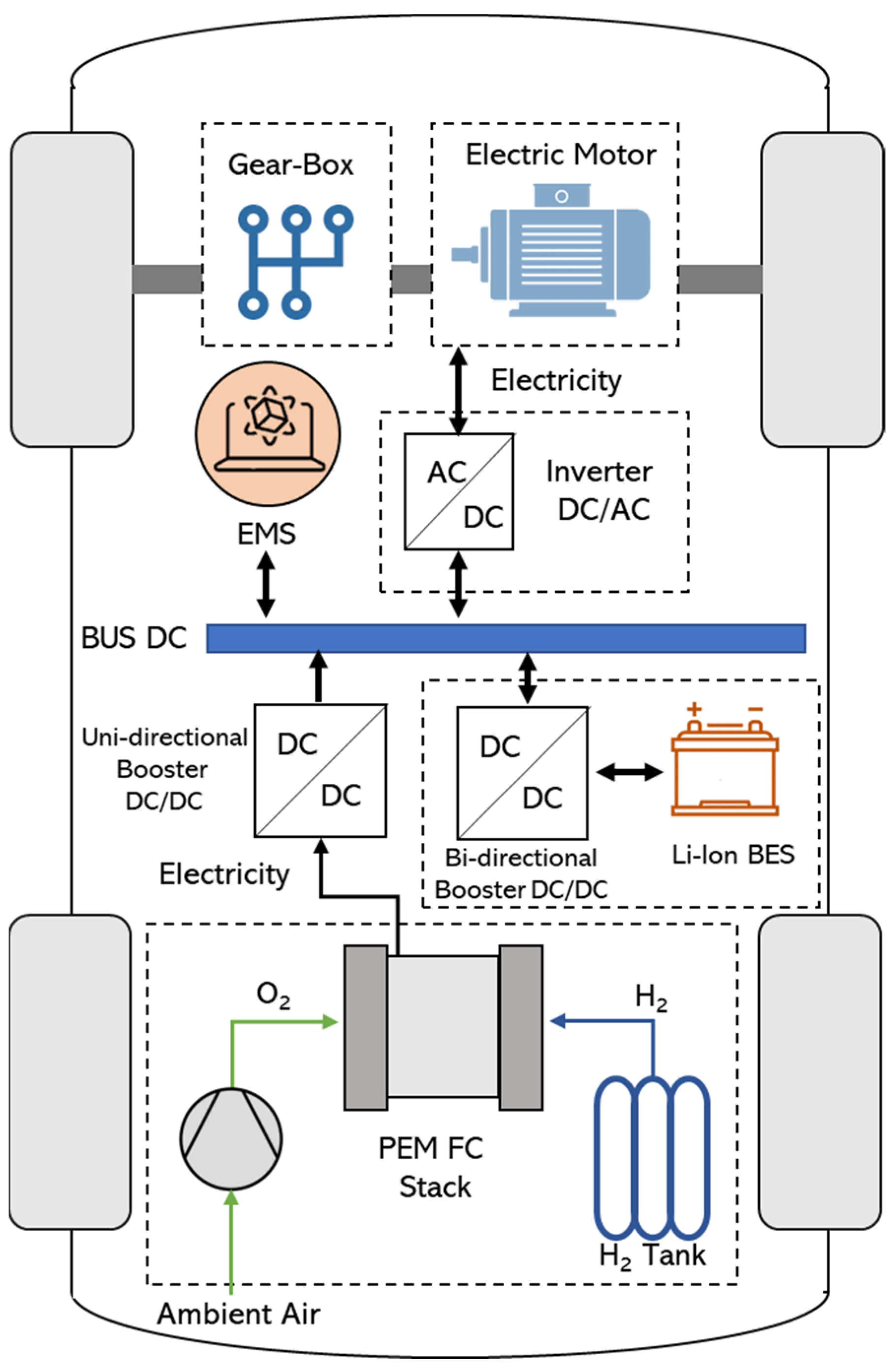
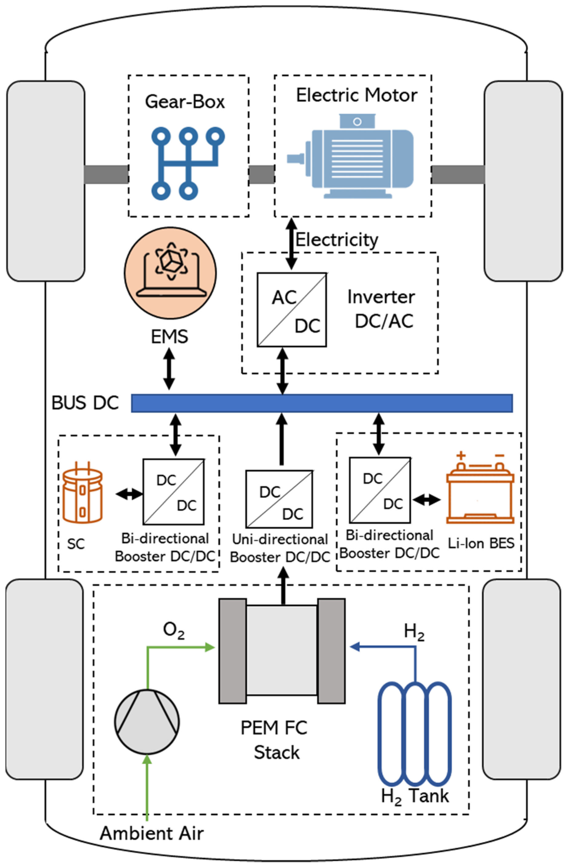
The first approach is based on the study of the scientific literature of the international relevance and the multi-year experience of the authors to present the possible layouts for fuel cell electric vehicles on the road. Four different configurations are discussed, considering the use of fuel cells, batteries and/or supercapacitors (SCs) as the energy sources of a vehicle and also considering the other components of a powertrain. For each configuration, the main features are highlighted, providing helpful remarks useful for characterizing and classifying the different layouts present;
-
The second approach is based on the study of commercial or R&D solutions for buses, trucks, and cars/SUVs, the presentation of their performance, and the use of company brochures and data sheets. In detail, by means of comprehensive research, the main size and performance of the most used hydrogen-powered vehicles for different applications, i.e., buses, trucks, and cars, are illustrated. Particular attention is focused on the fuel cell power, battery and/or SC energy capacity, and the driving range of the vehicle;
-
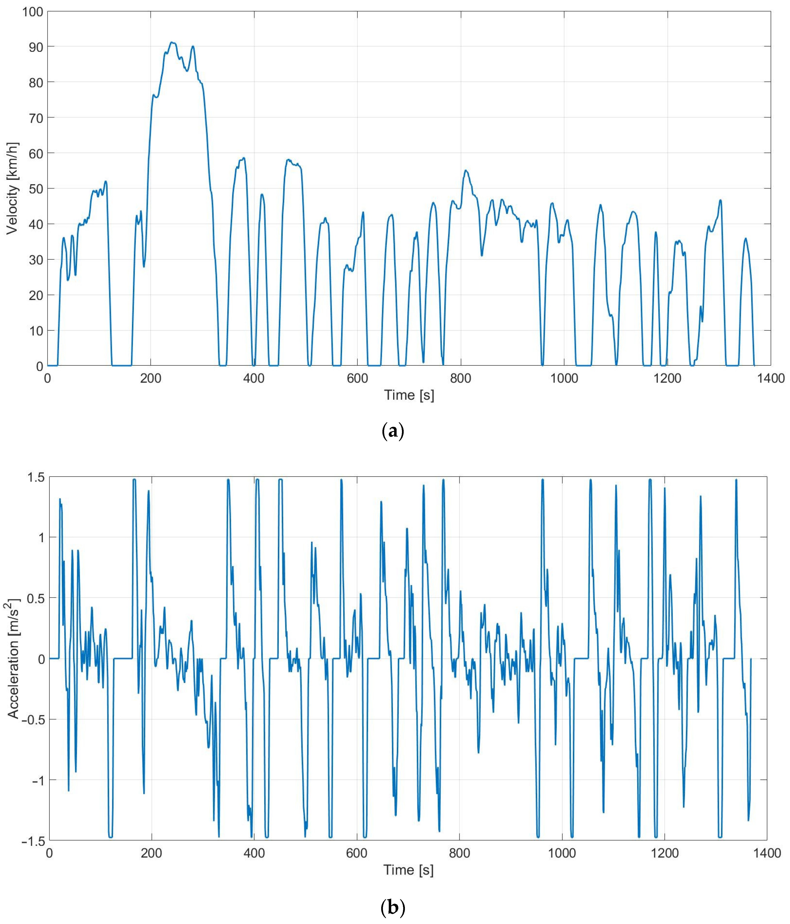
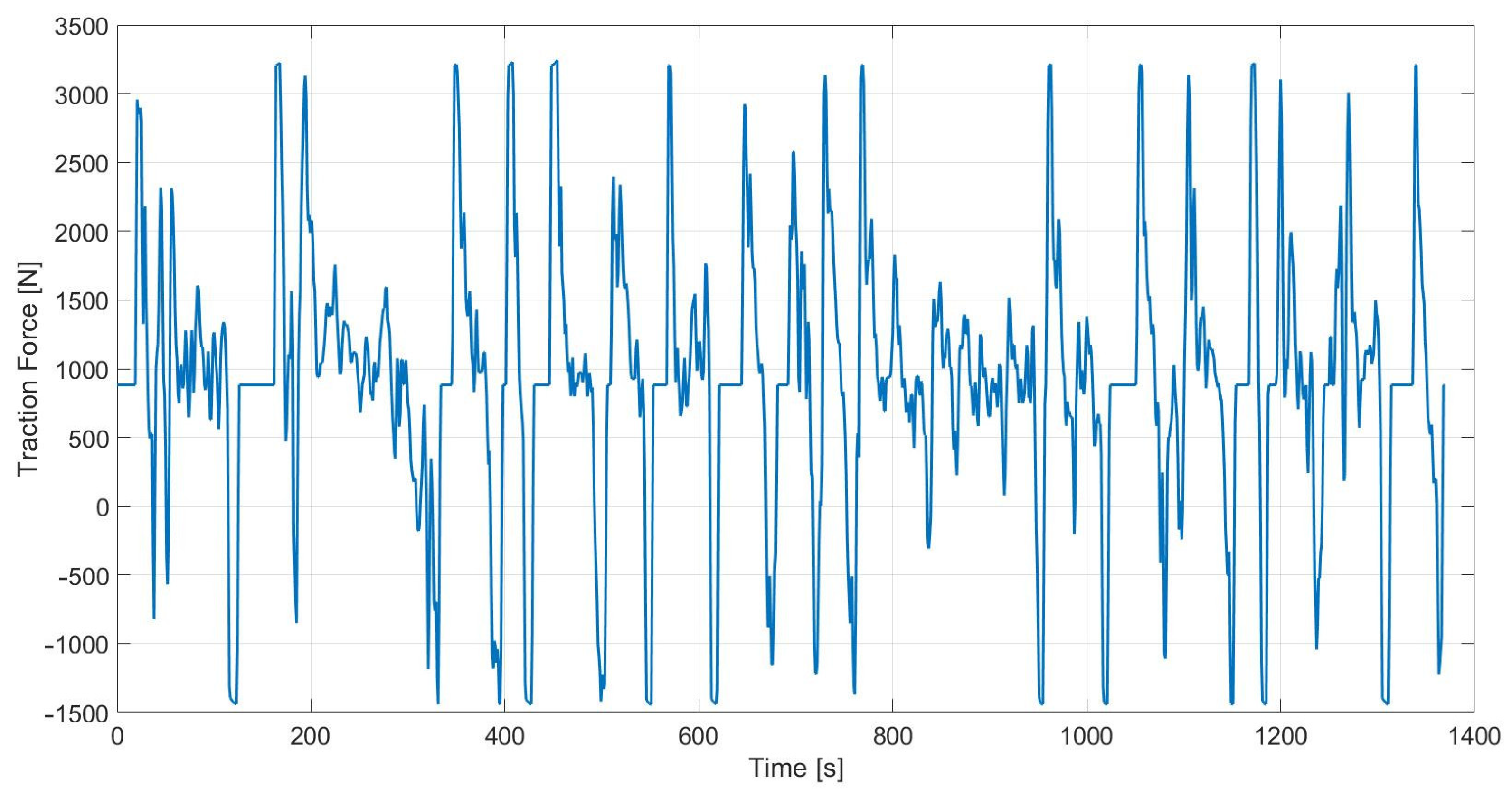
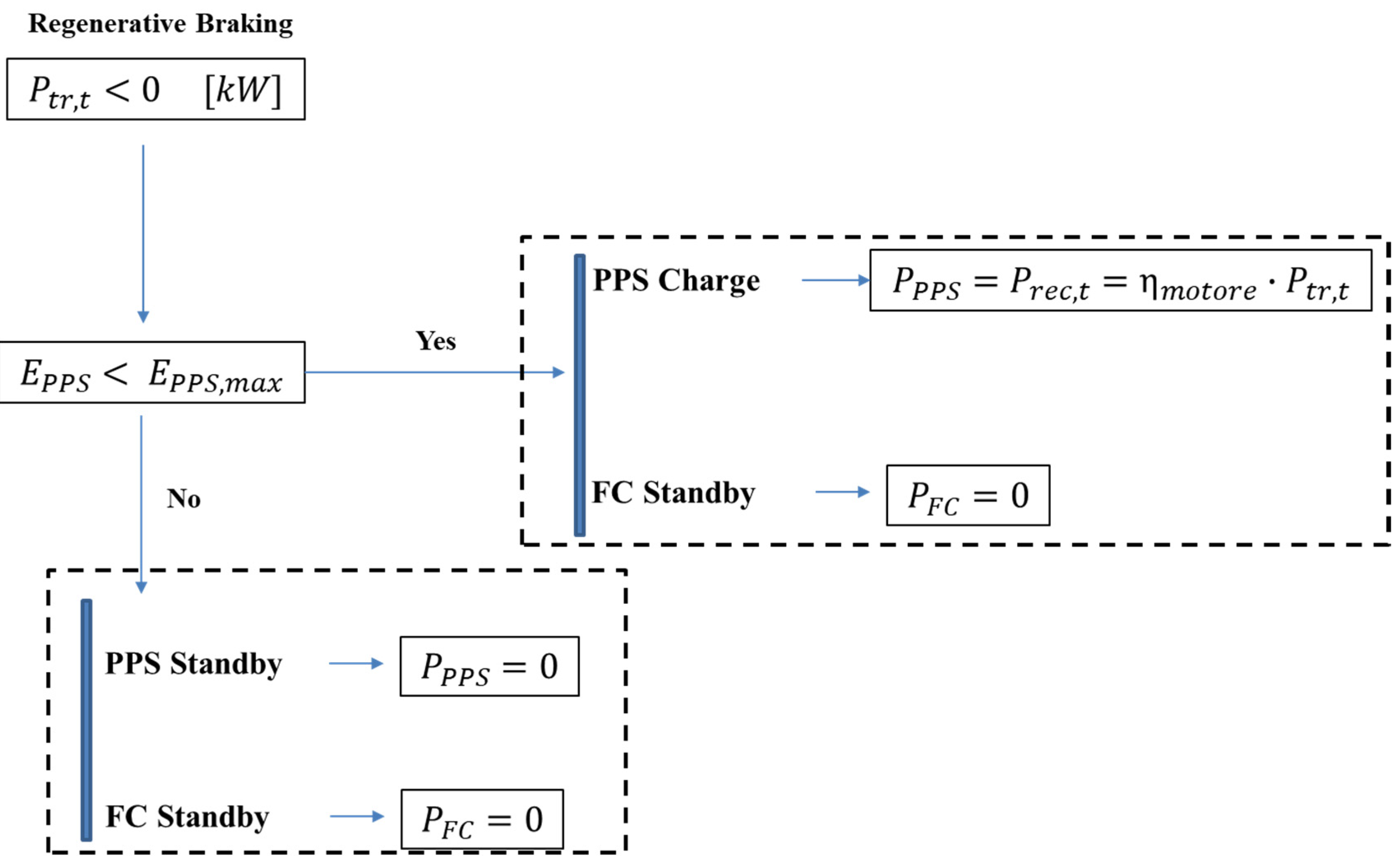
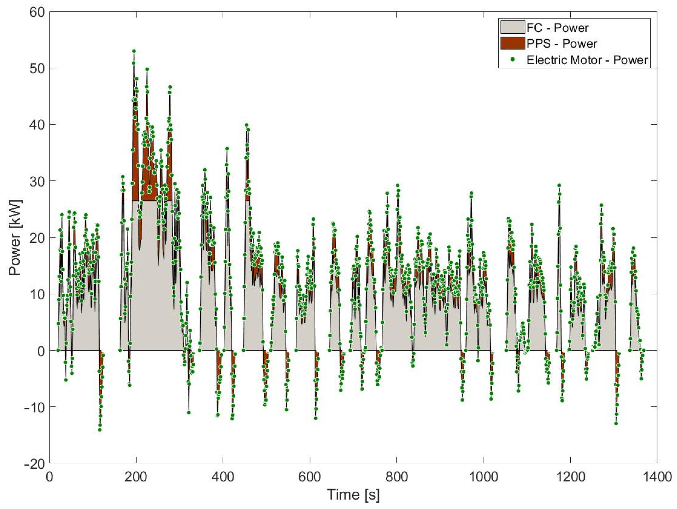
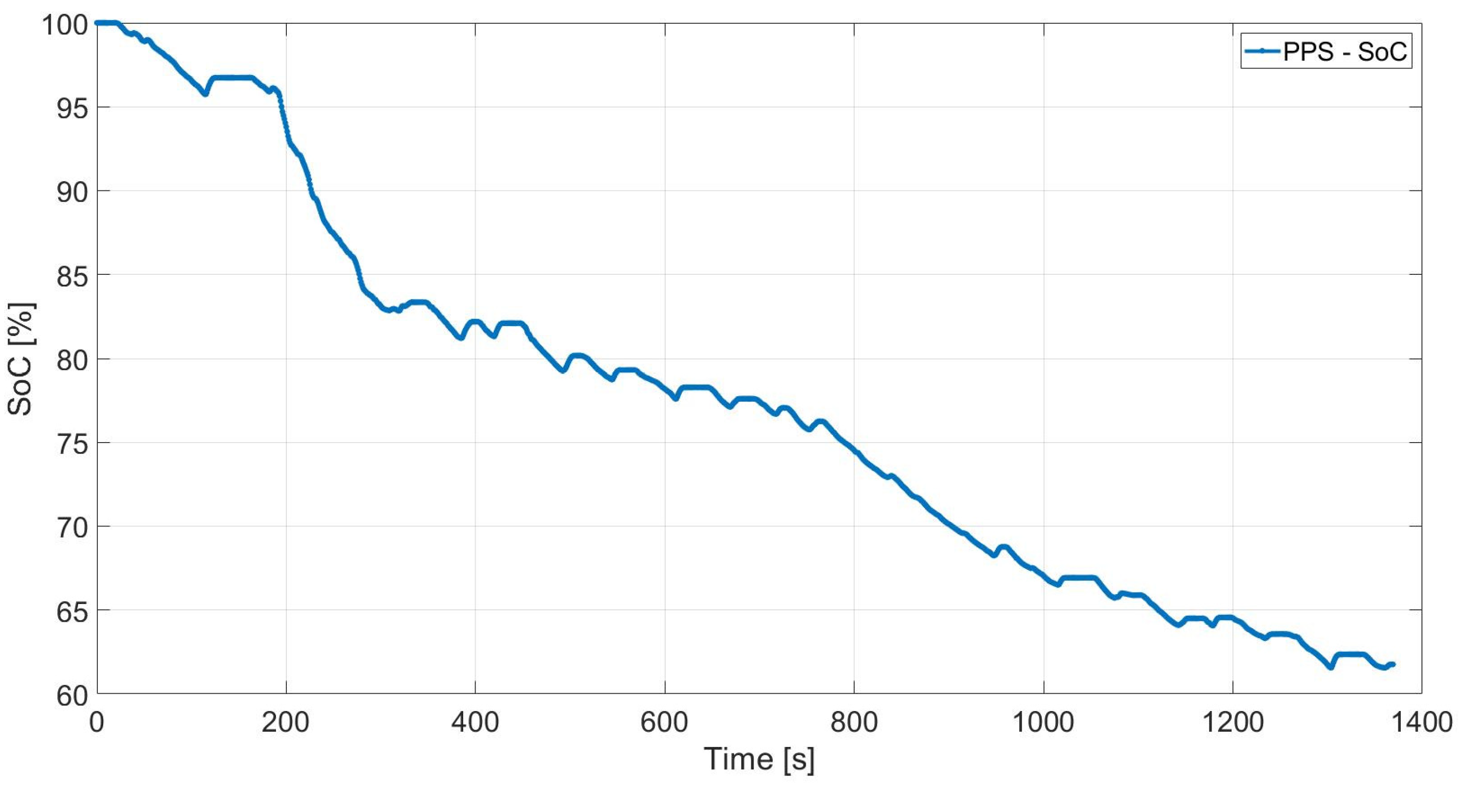
The third approach is a brief case study into a vehicles performance using hybrid fuel cell. This dynamic model is implemented ad hoc for the case study and is run in a Matlab/Simulink environment. The data from the EPA Urban Dynamometer drive cycle are used to achieve the power and energy demands of a passenger car, assuming a single-wheeled vehicle model. In addition, a simplified control strategy is implemented, which is capable of performing power-sharing between the energy sources, with the aim of investigating the fuel in the vehicles performance. The fuel cell and the battery power levels are discussed, showing the charging, and discharging phases, and takes into consideration the regenerative braking strategy.

3. Fuel Cell-Based Road Vehicle Layouts

Road fuel cell-based (FC-based) vehicles should be classified according to their powertrain architectures, voltage regulation strategy, inverters, and energy management strategies. Another classification for FC-based vehicles is based on the organization of the energy storage system and the propulsion system.
There are two primary FCEV configurations: a full FC-based powertrain and a hybridization of a powertrain with an FC-system. Accordingly, several hybridization patterns may be found in the literature. The present paper classifies the FC-based vehicles as follows: Figure 3, Figure 4, Figure 5 and Figure 6 depict Full FC or Total FC-based powertrains, FC as a Range Extender, FC + Battery Hybridization, and FC + Battery + SC Hybridization, respectively.
A fuel tank, an FC-stack, a DC–DC power converter, an inverter, and an electric motor constitute the Total FC-based powertrain (Figure 3). In addition to their structural simplicity, these vehicles have a long-range, rapid charging time, high efficiency, cold-start capability, silent operation owing to the lack of moving parts, energy continuity, and low emissions. FCEVs are well suited for low-speed vehicles, such as forklifts, buses, airline vehicles, trams, and marine vehicles.
According to the vehicle applications, driving range and refueling infrastructure, the storage systems and the thermodynamic status of hydrogen can change from configuration to configuration. Table 1 lists the main key performance indicators for four main hydrogen storage technologies: liquid hydrogen, compressed hydrogen at 35 MPa, compressed hydrogen at 70 MPa, and metal hydride storage. In the current state-of-the-art systems, hydrogen is commonly produced in centralized plants and is then transported to places of its final use, by means of compressed gas cylinders, or as liquefied hydrogen in cryogenic tanks. In mobility applications, compressed hydrogen gas technology (up to 700–800 bar) is currently preferred for on-board storage. Liquid hydrogen storage is technically challenging. Multi-level isolation tanks are used, consisting of an internal tank and an external container with an insulating vacuum between them. However, heat transfer cannot be completely ruled out. Nevertheless, new, and more efficient performance solutions, such as metal hydrides, are the subject of scientific and industrial research and development at an international level.
An FC-range extender vehicle (Figure 4) may improve its range by temporarily turning the stored hydrogen into electricity to fuel the electric motor. The energy storage of such powertrains serves only as a range extender, given the high energy density of the hydrogen energy system. While in the first configuration the fuel cell plays a primary role, in FC-range extender vehicles it offers support to the main energy source, i.e., the battery; for this reason, the FC-size is different among the two powertrains, assuming higher values in the first one.
The remaining two other configurations are hybrid layouts. For these vehicles, a power-sharing approach must be used in order to determine the operating range and the strategy needed for each power source.
For the fuel cell system, an energy ratio parameter or a power ratio parameter can be used. The former, called Energy Hybridization Degree, EHD, shown in Equation (1), represents the ratio between the energy provided by the fuel cell system during its operation in the drive cycle, considering the fuel cell power P F C , and the overall energy required by the powertrain, achievable from the overall power request P t o t . EHD is useful to define the power-sharing strategy of the fuel cell system:
E H D = t 0 t f P F C ( t ) · d t t 0 t f P t o t ( t ) · d t
The latter, the Power Hybridization Degree, PHD represents the ratio between the fuel cell nominal power, P F C , n o m , and the maximum power required by the powertrain, P t o t , m a x , as shown in Equation (2). The PHD is crucial to the size of the peaks in terms of power, and the role of the fuel cell system in managing them:
P H D = P F C , n o m P t o t , m a x
Figure 5 depicts the hybridization between FC and battery modules. A unidirectional DC–DC converter (UDC) connects the FC to the DC bus, while the battery is linked to a bidirectional DC–DC converter, to allow for the charging and discharging phases. The operational method of such configurations includes an initial start-up, provided by the battery, to prevent the FC from operating in the low-efficiency zone. Consequently, the battery offers a large current to operate the electric motor [30]. After the start-up phase, the fuel cell is triggered to sustain the electric motor’s running. The battery is then operated in accordance with the charge/discharge constraints. According to the value of the hybridization degrees, namely EHD and PHD, the energy source sizes are achieved; these values determine the energy demand distribution between the energy sources, hence, the refueling/recharging operations needed:
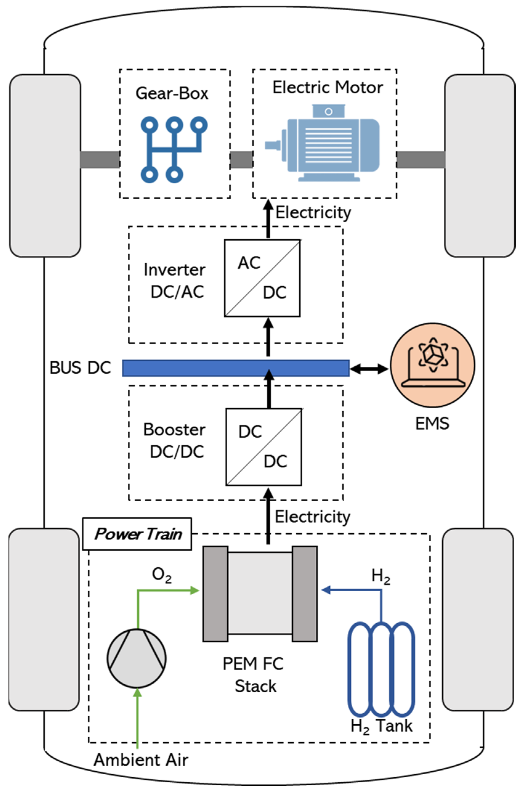
  • Only hydrogen refueling stations are used if all the energy is provided by the fuel cell (EHD equal to 1);
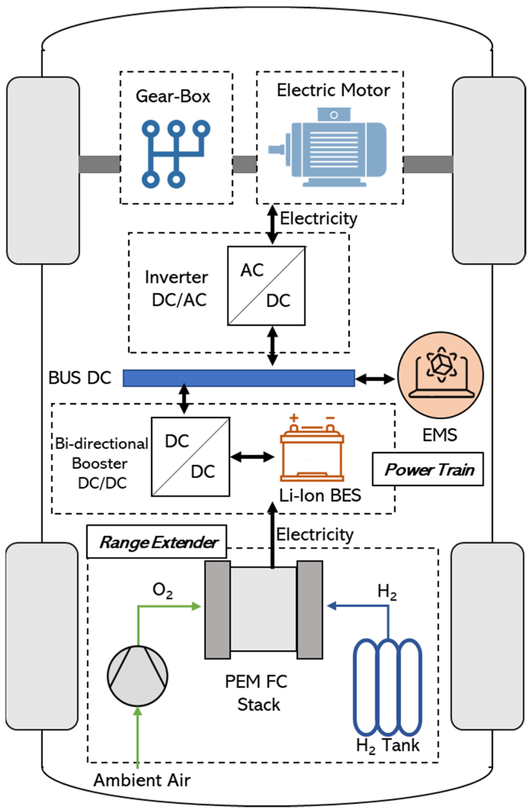
  • Hydrogen refueling and battery charging operations are needed when the EHD assumes a value different from 1.
The FC + Battery + SC hybridization (Figure 6) consists of a main energy source (FC) and two auxiliary units (battery and supercapacitor). In this configuration, a one-way DC–DC converter connects the FC to the DC bus. Bidirectional DC–DC converters link the energy storage units, the battery, and the SC to the DC bus (BDCs). This configuration provides continuous energy and increases the FC’s dynamic response during transient events, providing advantages over FC + battery and FC + SC systems. Nevertheless, the presence of three energy sources leads to a vehicle weight increment, which suggests the use of this powertrain especially in heavy-duty vehicles, and a further complexity of the control system.
Regarding the energy source sizing, also in this configuration, the hybridization degrees assume the same importance as in the FC + battery powertrain.

4. Fuel Cell Road Vehicle Overview

In this section, an overview of the main fuel cell road vehicles is carried out, considering the most important existing prototypes and the commercially available vehicles, for three different applications: buses, trucks, and cars.

4.1. Fuel Cell Electric Buses

A fuel cell electric bus is a bus that employs a hydrogen-fuel cell as the main power source for its electrically powered operation, which is occasionally hybridized with batteries or supercapacitors.
Several businesses have undertaken research into hydrogen-fuel cells and tested fuel cell buses. Among them, it is worthy to mention:
  • Daimler AG realized the new fuel cell, eCitaro range extender bus, powered by Toyota fuel cell stack, which will be launched in 2025 [31];
  • Thor Industries realized the ThunderPower hybrid fuel cell bus based on UTC Power fuel cell technology [32];
  • Irisbus realized the City Class fuel cell bus based on UTC Power fuel cell technology [33];
  • TATA Motors and Indian Oil Corporation realized Starbus fuel cell [34];
  • Van Hool and Ballard realized commercial fleets for passenger services in France (Van Hool’s A330 Fuel Cell Electric Bus) [35];
  • Solaris realized Urbino 12 [36];
  • CaetanoBus realized H2.City Gold fuel cell bus [31];
  • Rampini realized the H80 fuel cell bus [37];
  • French manufacturer Safra with Michelin’s subsidiary Symbio realized the fuel cell bus Safra Businova [38].
The main fuel cell bus characteristics are reported in Table 2, namely the fuel cell (FC) stack power, the battery (B) energy, and the vehicle’s range.

4.2. Fuel Cell Electric Trucks

A fuel cell truck is a heavy-duty vehicle that employs a hydrogen-fuel cell as its power source to operate with long mileage and high cargo loads. The fuel cell system may be supplemented in a hybrid configuration by batteries or supercapacitors.
Several truck manufacturers have conducted research and field experiments on hydrogen-fuel cell trucks. Among them are:
  • Hyundai realized the new Xcient fuel cell truck [31];
  • Nikola realized the new Two truck, based on Powercell fuel cell technology [39];
  • VDL realized the new truck based on Ballard fuel cell technology [40];
  • E-Trucks Europe realized the new truck based on Hydrogenics fuel cell technology [41];
  • Scania/Asko realized the new truck based on Hydrogenics fuel cell technology [40];
  • Renault realized the new truck based on Symbio fuel cell technology [42];
  • Esoro realized the new truck based on Swiss hydrogen-fuel cell technology [40];
  • Toyota realized the new Beta truck based on Toyota fuel cell technology [43];
  • US hybrid realized the new truck based on Toyota fuel cell technology [44];
  • Kenworth realized the new truck based on Ballard fuel cell technology [45].
The main fuel cell truck characteristics are reported in Table 3, i.e., the fuel cell (FC) stack power, the battery (B) energy, and the vehicle’s range.

4.3. Fuel Cell Electric Cars and SUVs

Fuel cell cars and Sport Utility Vehicles (SUV) are among the first commercial vehicle categories and light-duty vehicles where fuel cell technology was applied. Several car and SUV companies produced and are still producing fuel cell cars and SUVs. The main fuel cell cars and SUV characteristics are reported in Table 4, where fuel cell (FC) stack power, battery (B) energy, Supercapacitor (SC) energy, and vehicle’s range are reported.

5. Short Case Study

To give an overview of an FCEV performance in a hybrid configuration with a BES, this section presents a short description of a numerical model with some results. The vehicle under consideration is a passenger car, whose main features are listed in Table 5, with a frontal area of 2 m2 and a weight of 1.5 tons.
The vehicle is simulated by considering a drive-cycle retrieved from the EPA Urban Dynamometer Driving Schedule, which is one of the US Schedules to test vehicle emissions. The drive-cycle, as reported in Table 6, is characterized by a maximum speed of about 25 m/s, and an average speed of almost 9 m/s, for an overall length of 12 km, driven in 1369 s.
The acceleration ( a t ) profile was calculated by adopting the finite difference method, with a central finite difference [56], as described in Equation (3), considering the velocity profile ( v t ) and the time interval t t :
a t = v t + 1 v t 1 t t + 1 t t 1
The velocity and acceleration profiles are presented respectively in Figure 7a,b.
Once the velocity profile and acceleration profile versus time were calculated, the traction force of the vehicle, F t r , t , and the needed power P t r , t was estimated [57,58] by adopting Equations (4) and (5):
F t r , t = ( 1 + δ ) · M · d v d t + 1 2 · ρ a i r · C d r a g · A · v t 2 + M · g · f r · c o s ( α ) + M · g · s i n ( α )
P t r , t = F t r , t · v t
Figure 8 shows the traction force profile, which presents a maximum value of about 3.25 kN, and a minimum peak of −1.44 kN. There are moments when the force on the wheels is negative: it is then possible to provide regenerative braking, P r e c , by adopting Equation (6):
P r e c = η m o t o r e · P t r
If the traction is therefore negative, regenerative braking occurs, which recharges the battery energy system, also called the Power Peak shaving System (PPS). As shown in Figure 9, regenerative braking is used to charge the storage system when the traction power is negative; once the storage system is fully charged, the conventional braking system is engaged, without energy recovery.
The fuel cell system was sized by considering a PHD value of 50%, as shown in Equation (7), while the PPS energy system, E P P S ,   m a x , was sized with an EHD of 50% Equation (8):
P F C ,   n o m = P H D · P t o t , m a x = 0.5 · P t o t , m a x
E P P S ,   m a x = E H D · t 0 t f P t o t ( t ) · d t = 0.5 · t 0 t f P t o t ( t ) · d t
To determine the maximum power of the PPS system, a power-to-energy ratio of 14 was used, which represents the maximum power, expressed in kW, that the PPS system can provide as a function of the maximum storable energy. The minimum allowable energy in the PPS system is then expressed by Equation (9), assuming a minimum State of Charge (SoC) value of 25%:
S o C m i n · E P P S , m a x E P P S E P P S , m a x
Once the power sources are sized, as previously discussed, employing a control strategy is crucial when operating a hybrid vehicle. Since the electric motor’s efficiency (assumed equal to 84%) is known, the motor power, P e l , can be calculated:
P e l = P t r η m o t o r
As shown in Figure 10, there are three potential operating scenarios when the traction power is positive:
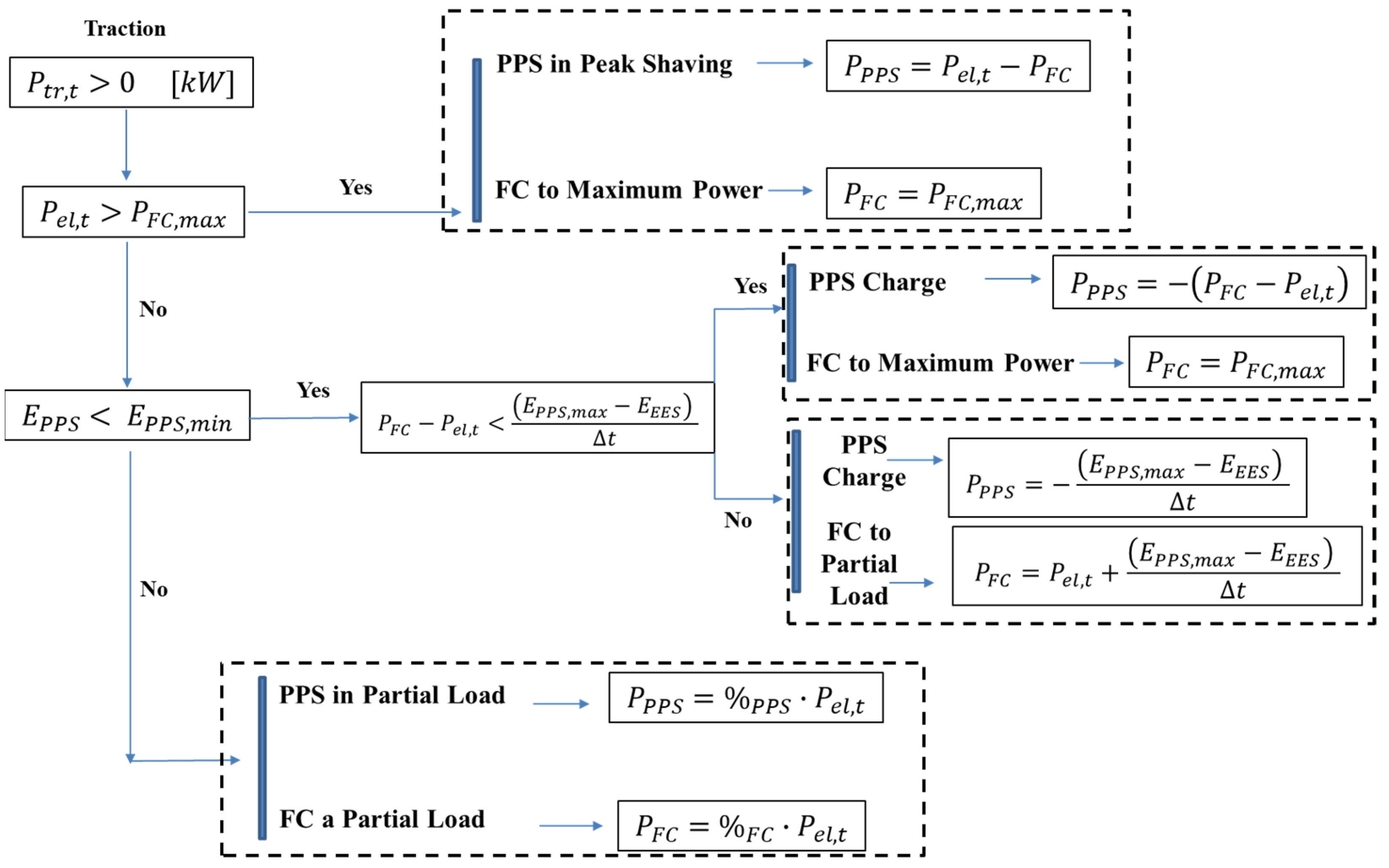
  • When the required power is greater than the fuel cell system’s maximum power, the fuel cell and the PPS system operate together, allowing the cell to operate at maximum power;
  • When the required power is lower than the fuel cell system’s maximum power and the storage system’s charge level is below the minimum state of charge value, the fuel cell operates at maximum power, allowing the excess to recharge the storage system. If the PPS state of charge is close to its maximum value, the fuel cell system is operated at partial load, providing both the traction power and the proper amount of power to fully charge the PPS system. A numerical example can clarify this operating strategy. If the electrical load requires 30 kW, it is possible to operate the fuel cell system at 30 kW and not charge the storage system, or it is possible to operate the fuel cell system at its maximum power, i.e., 40 kW, to fulfill the load and still have energy available to charge the storage system. If the difference between the power generated by the fuel cell and the power required by the electrical load exceeds the accumulated power in the storage system, the fuel cell cannot operate at maximum power and must instead operate at a power sufficient to recharge the storage system until its maximum capacity is reached.
  • If the power required is lower than the fuel cell system’s maximum power and the storage system has enough charge, it is possible to share the load between the two systems. Power sharing is offered when both the storage system and the fuel cell are used. The design choice to deliver 75% of the load from the cell and 25% from the battery means that the burden is split between the two systems. Power distribution decisions are usually made in accordance with guidelines established by system expertise, practical experience, and system optimization.
The results depicted in Figure 11 are then obtained by processing the data and comparing them on the same time–power graph. The green dots represent the motor’s required power peaks, which equal the sum of the power supplied by the cell and the storage system. As shown in the previous section, the maximum power of the cell is about 27 kW, leaving room for the energy storage system if the power demand exceeds this threshold. It is possible to consider the system’s control strategies by examining Figure 11. During the driving cycle, the power of the fuel cell never exceeds the electrical power required by the vehicle, so the cell will never charge the battery: There should be instances in which the power of the fuel cell exceeds the power required by the vehicle to meet demand, and the excess power is used to recharge the cell. This results in an operation of the PPS system that never reaches its minimum value and therefore it does not need to be charged. Instead, regenerative braking recharges the battery during braking. From the energy level of the storage system, shown in Figure 12, it is possible to observe how the storage system is fully charged at time 0 and how it tends to discharge, with the exception of time, when regenerative braking is applied, but without reaching the lowest possible energy value within the considered span of time.

6. Conclusions

In the present paper hydrogen-fuel cell hybrid powertrains are deeply analyzed in terms of conceptual layouts, operating solutions, and energy performance. Three different approaches are considered, aiming to comprehensively investigate fuel cell applications in the road sector.
In the first one, possible layouts for fuel cell road vehicles are shown, i.e., Full FC, FC Range Extender, FC + Battery, FC + Battery + UC, highlighting the device role, principal operations, sizing methods, and the applications for each configuration.
The second approach focuses on the study of commercial or R&D solutions for buses, trucks, and cars/SUVs, through a comprehensive overview of real and current applications, stressing the main key performance indicators, such as efficiency, mileage, and energy consumption. In detail, for buses, the fuel cell stack power varies between 16 kW and 85 kW, with a range between 170 km and 400 km for Rampini Hydrogen Alè and Caetano Hydrogen Busses respectively. Instead, for trucks, the nominal fuel cell stack power is in an interval between 20 kW and 226 kW, achieving a driving range starting from 200 km, for the Renault Maxity H2, up to 1200 for the Nikola Two model. Regarding car applications, the fuel cell stacks reach a power between 64 and 128 kW, with a range between 160 km (for the Mercedes-Benz F-Cell A-Class) and 647 km (for the Toyota Mirai).
In the last approach, a brief case study of hybrid fuel cell vehicle performance is analyzed by means of a numerical model, assuming a vehicle model based on lumped parameters, tested on the EPA Urban Dynamometer Driving Schedule. The control system implemented allows a maximum fuel cell power of 27 kW, while the surplus is provided by the battery. In addition, the battery starts fully charged and ends its cycle with a SOC value of 63%, thanks to the regenerative braking strategy implemented, in line with the hybridization degrees imposed.
The results achieved testify how fuel cell vehicles can constitute a feasible and high-performing solution for the future, with the aim of reducing the onerous impact of the road transport sector.

Author Contributions

Conceptualization, P.F., M.G., F.P., O.C. and G.D.L.; Data curation, P.F., M.G., F.P., O.C. and G.D.L.; Formal analysis, P.F., M.G., F.P., O.C. and G.D.L.; Funding acquisition, P.F., M.G., F.P., O.C. and G.D.L.; Investigation, P.F., M.G., F.P., O.C. and G.D.L.; Methodology, P.F., M.G., F.P., O.C. and G.D.L.; Project administration, P.F., M.G., F.P., O.C. and G.D.L.; Resources, P.F., M.G., F.P., O.C. and G.D.L.; Software, P.F., M.G., F.P., O.C. and G.D.L.; Supervision, P.F., M.G., F.P., O.C. and G.D.L.; Validation, P.F., M.G., F.P., O.C. and G.D.L.; Visualization, P.F., M.G., F.P., O.C. and G.D.L.; Writing—original draft, P.F., M.G., F.P., O.C. and G.D.L.; Writing—review & editing, P.F., M.G., F.P., O.C. and G.D.L. All authors have read and agreed to the published version of the manuscript.

Funding

This research received no external funding.

Institutional Review Board Statement

Not applicable.

Informed Consent Statement

Not applicable.

Data Availability Statement

Not applicable.

Conflicts of Interest

The authors declare no conflict of interest.

References

  1. Kellogg, W.W.; Schware, R. Climate Change and Society: Consequences of Increasing Atmospheric Carbon Dioxide; Routledge: New York, NY, USA, 2019; ISBN 978-0-429-04873-9. [Google Scholar]
  2. Abanades, J.C.; Rubin, E.S.; Mazzotti, M.; Herzog, H.J. On the Climate Change Mitigation Potential of CO2 Conversion to Fuels. Energy Environ. Sci. 2017, 10, 2491–2499. [Google Scholar] [CrossRef]
  3. A European Strategy for Low-Emission Mobility—European Environment Agency. Available online: https://www.eea.europa.eu/policy-documents/a-european-strategy-for-low (accessed on 26 August 2022).
  4. Staffell, I.; Scamman, D.; Abad, A.V.; Balcombe, P.; Dodds, P.E.; Ekins, P.; Shah, N.; Ward, K.R. The Role of Hydrogen and Fuel Cells in the Global Energy System. Energy Environ. Sci. 2019, 12, 463–491. [Google Scholar] [CrossRef] [Green Version]
  5. World Energy Outlook 2017—Analysis. Available online: https://www.iea.org/reports/world-energy-outlook-2017 (accessed on 26 August 2022).
  6. World Energy Balances—Data Product. Available online: https://www.iea.org/data-and-statistics/data-product/world-energy-balances (accessed on 26 August 2022).
  7. EU Hydrogen Policy: Hydrogen as an Energy Carrier for a Climate-Neutral Economy | Think Tank | European Parliament. Available online: https://www.europarl.europa.eu/thinktank/en/document/EPRS_BRI(2021)689332 (accessed on 26 August 2022).
  8. Liu, X.; Reddi, K.; Elgowainy, A.; Lohse-Busch, H.; Wang, M.; Rustagi, N. Comparison of Well-to-Wheels Energy Use and Emissions of a Hydrogen Fuel Cell Electric Vehicle Relative to a Conventional Gasoline-Powered Internal Combustion Engine Vehicle. Int. J. Hydrog. Energy 2020, 45, 972–983. [Google Scholar] [CrossRef]
  9. Chen, Z.; Ma, Z.; Zheng, J.; Li, X.; Akiba, E.; Li, H.-W. Perspectives and Challenges of Hydrogen Storage in Solid-State Hydrides. Chin. J. Chem. Eng. 2021, 29, 1–12. [Google Scholar] [CrossRef]
  10. Hassan, I.A.; Ramadan, H.S.; Saleh, M.A.; Hissel, D. Hydrogen Storage Technologies for Stationary and Mobile Applications: Review, Analysis and Perspectives. Renew. Sustain. Energy Rev. 2021, 149, 111311. [Google Scholar] [CrossRef]
  11. Li, Y.; Taghizadeh-Hesary, F. The Economic Feasibility of Green Hydrogen and Fuel Cell Electric Vehicles for Road Transport in China. Energy Policy 2022, 160, 112703. [Google Scholar] [CrossRef]
  12. Ajanovic, A.; Haas, R. Prospects and Impediments for Hydrogen and Fuel Cell Vehicles in the Transport Sector. Int. J. Hydrog. Energy 2021, 46, 10049–10058. [Google Scholar] [CrossRef]
  13. Duan, Z.; Mei, N.; Feng, L.; Yu, S.; Jiang, Z.; Chen, D.; Xu, X.; Hong, J. Research on Hydrogen Consumption and Driving Range of Hydrogen Fuel Cell Vehicle under the CLTC-P Condition. World Electr. Veh. J. 2022, 13, 9. [Google Scholar] [CrossRef]
  14. Cunanan, C.; Tran, M.-K.; Lee, Y.; Kwok, S.; Leung, V.; Fowler, M. A Review of Heavy-Duty Vehicle Powertrain Technologies: Diesel Engine Vehicles, Battery Electric Vehicles, and Hydrogen Fuel Cell Electric Vehicles. Clean Technol. 2021, 3, 474–489. [Google Scholar] [CrossRef]
  15. Fan, L.; Tu, Z.; Chan, S.H. Recent Development of Hydrogen and Fuel Cell Technologies: A Review. Energy Rep. 2021, 7, 8421–8446. [Google Scholar] [CrossRef]
  16. Cigolotti, V.; Genovese, M.; Fragiacomo, P. Comprehensive Review on Fuel Cell Technology for Stationary Applications as Sustainable and Efficient Poly-Generation Energy Systems. Energies 2021, 14, 4963. [Google Scholar] [CrossRef]
  17. Sinigaglia, T.; Lewiski, F.; Santos Martins, M.E.; Mairesse Siluk, J.C. Production, Storage, Fuel Stations of Hydrogen and Its Utilization in Automotive Applications-a Review. Int. J. Hydrog. Energy 2017, 42, 24597–24611. [Google Scholar] [CrossRef]
  18. Rivard, E.; Trudeau, M.; Zaghib, K. Hydrogen Storage for Mobility: A Review. Materials 2019, 12, 1973. [Google Scholar] [CrossRef] [Green Version]
  19. Singh, R.; Singh, M.; Gautam, S. Hydrogen Economy, Energy, and Liquid Organic Carriers for Its Mobility. Mater. Today Proc. 2021, 46, 5420–5427. [Google Scholar] [CrossRef]
  20. Cullen, D.A.; Neyerlin, K.C.; Ahluwalia, R.K.; Mukundan, R.; More, K.L.; Borup, R.L.; Weber, A.Z.; Myers, D.J.; Kusoglu, A. New Roads and Challenges for Fuel Cells in Heavy-Duty Transportation. Nat. Energy 2021, 6, 462–474. [Google Scholar] [CrossRef]
  21. İnci, M.; Büyük, M.; Demir, M.H.; İlbey, G. A Review and Research on Fuel Cell Electric Vehicles: Topologies, Power Electronic Converters, Energy Management Methods, Technical Challenges, Marketing and Future Aspects. Renew. Sustain. Energy Rev. 2021, 137, 110648. [Google Scholar] [CrossRef]
  22. Fragiacomo, P.; Piraino, F.; Genovese, M.; Corigliano, O.; Lorenzo, G.D. Strategic Overview on Fuel Cell-Based Systems for Mobility and Electrolytic Cells for Hydrogen Production. Procedia Comput. Sci. 2022, 200, 1254–1263. [Google Scholar] [CrossRef]
  23. Kulkarni, A.; Siahrostami, S.; Patel, A.; Nørskov, J.K. Understanding Catalytic Activity Trends in the Oxygen Reduction Reaction. Chem. Rev. 2018, 118, 2302–2312. [Google Scholar] [CrossRef] [PubMed]
  24. Piraino, F.; Fragiacomo, P. Design of an Equivalent Consumption Minimization Strategy-Based Control in Relation to the Passenger Number for a Fuel Cell Tram Propulsion. Energies 2020, 13, 4010. [Google Scholar] [CrossRef]
  25. Iranzo, A.; Arredondo, C.H.; Kannan, A.M.; Rosa, F. Biomimetic Flow Fields for Proton Exchange Membrane Fuel Cells: A Review of Design Trends. Energy 2020, 190, 116435. [Google Scholar] [CrossRef]
  26. Li, H.; Tang, Y.; Wang, Z.; Shi, Z.; Wu, S.; Song, D.; Zhang, J.; Fatih, K.; Zhang, J.; Wang, H.; et al. A Review of Water Flooding Issues in the Proton Exchange Membrane Fuel Cell. J. Power Sources 2008, 178, 103–117. [Google Scholar] [CrossRef]
  27. Alazemi, J.; Andrews, J. Automotive Hydrogen Fuelling Stations: An International Review. Renew. Sustain. Energy Rev. 2015, 48, 483–499. [Google Scholar] [CrossRef]
  28. Zhang, Y.; Shi, J.; Zhou, L.; Li, J.; Sumner, M.; Wang, P.; Xia, C. Wide Input-Voltage Range Boost Three-Level DC–DC Converter With Quasi-Z Source for Fuel Cell Vehicles. IEEE Trans. Power Electron. 2017, 32, 6728–6738. [Google Scholar] [CrossRef]
  29. Path to Hydrogen Competitiveness: A Cost Perspective—Hydrogen Council. Available online: https://hydrogencouncil.com/en/ (accessed on 26 September 2022).
  30. Ehsani, M.; Gao, Y.; Longo, S.; Ebrahimi, K. Modern Electric, Hybrid Electric, and Fuel Cell Vehicles, 3rd ed.; CRC Press: Boca Raton, FL, USA, 2018; ISBN 978-0-429-50488-4. [Google Scholar]
  31. Hart, D.; Jones, S.; Lewis, J. The Fuel Cell Industry Review 2020; Hydrogen Knowledge Centre: Derby, UK, 2020. [Google Scholar]
  32. Chandler, K.; Eudy, L. Battelle Memorial Institute Fuel Cell Transit Buses: ThunderPower Bus Evaluation at SunLine Transit Agency; Dept. of Energy. Office of Energy Efficiency and Renewable Energy (US), 2003. Available online: https://rosap.ntl.bts.gov/view/dot/34679 (accessed on 26 September 2022).
  33. Mercuri, R.; Bauen, A.; Hart, D. Options for Refuelling Hydrogen Fuel Cell Vehicles in Italy. J. Power Sources 2002, 106, 353–363. [Google Scholar] [CrossRef]
  34. Recent Advances, Unsolved Deficiencies, and Future Perspectives of Hydrogen Fuel Cells in Transportation and Portable Sectors—Rath—2019—International Journal of Energy Research—Wiley Online Library. Available online: https://onlinelibrary.wiley.com/doi/abs/10.1002/er.4795 (accessed on 26 September 2022).
  35. Edwards, T.; Eudy, L. SunLine Expands Horizons with Fuel Cell Bus Demo; SunLine Transit Agency, National Renewable Energy Laboratory (U.S.), 2006. Available online: https://rosap.ntl.bts.gov/view/dot/34821 (accessed on 26 September 2022).
  36. Trovao, J.P. Automotive Electronics Under the COVID-19 Shadow [Automotive Electronics]. IEEE Veh. Technol. Mag. 2020, 15, 101–108. [Google Scholar] [CrossRef]
  37. De Lorenzo, G.; Andaloro, L.; Sergi, F.; Napoli, G.; Ferraro, M.; Antonucci, V. Numerical Simulation Model for the Preliminary Design of Hybrid Electric City Bus Power Train with Polymer Electrolyte Fuel Cell. Int. J. Hydrog. Energy 2014, 39, 12934–12947. [Google Scholar] [CrossRef]
  38. HYCITY: Hydrogen Bus—Manufacturer—Safra—Albi. Available online: https://safra.fr/en/manufacturer/ (accessed on 26 September 2022).
  39. Danebergs, J. Techno-Economic Study of Hydrogen as a Heavy-Duty Truck Fuel. A Case Study on the Transport Corridor Oslo—Trondheim. Master’s Thesis, Universitat Politècnica de Catalunya, Barcelona, Spain, 2020. [Google Scholar]
  40. Report: Survey of Heavy-Duty Hydrogen Fuel Cell Electric Vehicles and Their Fit for Service in Canada. Available online: https://transitionaccelerator.ca/survey-of-heavy-duty-hydrogen-fuel-cell-electric-vehicles-and-their-fit-for-service-in-canada/ (accessed on 26 September 2022).
  41. Report: Akac, A.; Mathioulakis. M. Best Practices in Hydrogen Electromobility with Potential Appliance in Phocis Region. Available online: https://www.dimosdelfon.gr/attachments/article/5075/Best%20practicies%20in%20hydrogen%20electromobility%20with%20potential%20appliance%20in%20Phocis%20Region.pdf (accessed on 26 September 2022).
  42. Technological Maturity Level and Market Introduction Timeline of Zero-Emission Heavy-Duty Vehicles. Available online: https://www.toi.no/publications/technological-maturity-level-and-market-introduction-timeline-of-zero-emission-heavy-duty-vehicles-article35164-29.html (accessed on 26 September 2022).
  43. Estimating the Infrastructure Needs and Costs for the Launch of Zero-Emission Trucks. International Council on Clean Transportation. 2019, pp. 1–3. Available online: https://www.researchgate.net/profile/Nicholas-Lutsey/publication/335104931_Estimating_the_infrastructure_needs_and_costs_for_the_launch_of_zero-emission_trucks/links/5d4f9cda299bf1995b759d35/Estimating-the-infrastructure-needs-and-costs-for-the-launch-of-zero-emission-trucks.pdf (accessed on 26 September 2022).
  44. Report: Zero-Emission Drayage Truck Demonstration (ZECT I). Available online: https://www.energy.gov/sites/prod/files/2015/07/f24/vss115_choe_2015_o.pdf (accessed on 26 September 2022).
  45. Wang, H.; Gaillard, A.; Li, Z.; Roche, R.; Hissel, D. Multiple-Fuel Cell Module Architecture Investigation: A Key to High Efficiency in Heavy-Duty Electric Transportation. IEEE Veh. Technol. Mag. 2022, 17, 94–103. [Google Scholar] [CrossRef]
  46. Kawasaki, S.; Ono, T.; Ogura, M.; Kami, Y. Development of the Honda FCX Fuel Cell Vehicle. Introd. New Technol. 2003, 15, 6. [Google Scholar]
  47. Wyczalek, F. Energy Independence—A Nation Running on Empty. In 3rd International Energy Conversion Engineering Conference; American Institute of Aeronautics and Astronautics: San Francisco, CA, USA, 2005. [Google Scholar]
  48. Introducing the 2005 Model Year X-Trail Fcv. Available online: https://cyberleninka.ru/article/n/introducing-the-2005-model-year-x-trail-fcv/viewer (accessed on 26 September 2022).
  49. Ballard, Daimler Extend Service Contract for Hamburg Buses. Fuel Cells Bull. 2008, 2008, 2–3. [CrossRef]
  50. Eberle, U. Hydrogen for Automotive Applications and Beyond. Dept. of Energy. Office of Scientific and Technical Information (US) 2010. Available online: https://www.osti.gov/etdeweb/biblio/21360658 (accessed on 26 September 2022).
  51. Matsunaga, M.; Fukushima, T.; Ojima, K. Advances in the Power Train System of Honda FCX Clarity Fuel Cell Vehicle; SAE International: Warrendale, PA, USA, 2009. [Google Scholar]
  52. Mohrdieck, D.C. Next Generation Fuel Cell Technology for Passenger Cars and Buses. World Electr. Veh. J. 2009, 3, 209–213. [Google Scholar] [CrossRef] [Green Version]
  53. Robledo, C.B.; Poorte, M.J.; Mathijssen, H.H.M.; van der Veen, R.A.C.; van Wijk, A.J.M. Fuel Cell Electric Vehicle-to-Grid Feasibility: A Technical Analysis of Aggregated Units Offering Frequency Reserves. In Intelligent Integrated Energy Systems: The PowerWeb Program at TU Delft; Palensky, P., Cvetković, M., Keviczky, T., Eds.; Springer: Cham, Switzerland, 2019; pp. 167–194. ISBN 978-3-030-00057-8. [Google Scholar]
  54. Matsunaga, M.; Fukushima, T.; Ojima, K. Powertrain System of Honda FCX Clarity Fuel Cell Vehicle. World Electr. Veh. J. 2009, 3, 820–829. [Google Scholar] [CrossRef]
  55. Lohse-Busch, H.; Stutenberg, K.; Duoba, M.; Iliev, S. Technology Assessment of A Fuel Cell Vehicle: 2017 Toyota Mirai; Argonne National Lab. (ANL): Argonne, IL, USA, 2018. [Google Scholar]
  56. Di Trolio, P.; Di Giorgio, P.; Genovese, M.; Frasci, E.; Minutillo, M. A Hybrid Power-Unit Based on a Passive Fuel Cell/Battery System for Lightweight Vehicles. Appl. Energy 2020, 279, 115734. [Google Scholar] [CrossRef]
  57. Fragiacomo, P.; Piraino, F. Fuel Cell Hybrid Powertrains for Use in Southern Italian Railways. Int. J. Hydrog. Energy 2019, 44, 27930–27946. [Google Scholar] [CrossRef]
  58. Fragiacomo, P.; Piraino, F. Numerical Modelling of a PEFC Powertrain System Controlled by a Hybrid Strategy for Rail Urban Transport. J. Energy Storage 2018, 17, 474–484. [Google Scholar] [CrossRef]
Figure 1. Energy Consumption for the transport sector in Europe.
Machines 10 01121 g001
Figure 2. Size powers of the FCEVs in different transportation systems over the traveled distance.
Machines 10 01121 g002
Figure 3. Total fuel cell Electric Vehicle.
Machines 10 01121 g003
Figure 4. Fuel cell Range Extender Configuration for Electric Vehicles.
Machines 10 01121 g004
Figure 5. Fuel Cell Hybrid Electric Vehicle Configuration, with Fuel Cell and Battery Energy Systems.
Machines 10 01121 g005
Figure 6. Fuel cell Hybrid Electric Vehicle Configuration, with Fuel Cell, Battery, and Super-Capacitor Energy Systems.
Machines 10 01121 g006
Figure 7. Drive Cycle: (a) Velocity Profile and (b) Acceleration Profile.
Machines 10 01121 g007
Figure 8. Drive Cycle and Traction Force.
Machines 10 01121 g008
Figure 9. Regenerative Braking Strategy.
Machines 10 01121 g009
Figure 10. Traction Strategy.
Machines 10 01121 g010
Figure 11. Power Sharing among Fuel Cell and Battery Systems.
Machines 10 01121 g011
Figure 12. SOC Profile vs. Time.
Machines 10 01121 g012
Table 1. Main characteristics of Hydrogen Storage Technologies.
ParameterLiquid
Hydrogen
Compressed Gaseous
Hydrogen-35 MPa
Compressed Gaseous
Hydrogen-70 MPa
Metal Hydride
Storage
Gravimetric Energy Density [kWh/kg]21.61.80.4
Volumetric Energy Density [kWh/dm3]1.20.50.90.8
Thermodynamic Density [kg/m3] @25 °C7023.339.3-
Operating Temperature and PressureCryogenic, slightly above atmospheric pressureCompatible with vehicle operating temperature, high pressureCompatible with vehicle operating temperature, high pressureCompatible with vehicle operating temperature, low pressure
Technology Readiness Level (TRL)4–7994–7
Table 2. Main characteristics of fuel cell Buses.
Bus ModelFC-Stack Power [kW]B Energy [kWh]Range [km]FC TypeStorage and Pressure Level
Fuel cell eCitaro range extender bus [31]60243350–400PEM-FC35 kg, 35 MPa
ThunderPower hybrid fuel cell bus [32]6026240–320PEM-FC25 kg, 25 MPa
City Class fuel cell bus [33]6048200PEM-FC1260 L
Starbus fuel cell [34]8536300–350PEM-FC820 L, 14.5 kg
Van Hool’s A330 Fuel Cell Electric Bus [35]8524300PEM-FC38 kg, 35 MPa
Urbino 12 Hydrogen [36]7048350PEM-FC37 kg, 35 MPa
Caetano Hydrogen Bus [31]6044400PEM-FC37.5 kg, 35 MPa
Rampini Hydrogen Alè Bus [37]1680–90170–190PEM-FC2 × 4.89 kg, 35 MPa
Safra HyCity [38]45130350PEM-FC35 kg, 35 MPa
Table 3. Main characteristics of fuel cell Trucks.
Truck ModelFC-Stack Power [kW]B Energy [kWh]Range [km]FC TypeStorage and Pressure Level
Hyundai Xcient fuel cell [31]18078.4400PEM-FC32.09 kg, 35 MPa
Nikola Two truck [39]200250800–1200PEM-FC80 kg, 70 MPa
VDL [40]8884400PEM-FCNA
E-Trucks Europe [41]40154400PEM-FC15 kg
Scania/Asko [40]9056400–500PEM-FC33 kg, 35 MPa
Renault Maxity H2 [42]2042200PEM-FC8 kg, 35 MPa
Esoro FC truck [40]100120375–400PEM-FC31 kg, 35 MPa
Toyota Beta truck [43]22612482PEM-FC40 kg, 70 MPa
US hybrid truck [44]8030320PEM-FC25 kg, 35 MPa
Kenworth truck [45]85100320PEM-FC60 kg, 70 MPa
Table 4. List of fuel cell Cars and SUVs in production and out-of-production models with their driving range.
Car ModelFC-Stack Power [kW]B Energy [kWh]SC Energy [kWh]Range
[km]
FC TypeStorage and Pressure Level
Honda FCX [46]78-1.4315PEM-FC156.6 L, 35 MPa
Ford Focus FCV [47]7523-320PEM-FC178 L, 35 MPa
Nissan X-Trail FCV 04 [48]8540-over 350PEM-FC70 MPa
Mercedes-Benz F-Cell A-Class based [49]641.4-160PEM-FC1.8 kg, 35 MPa
Chevrolet Equinox FC [50]931.8-310PEM-FC4.2 kg, 70 MPa
Honda FCX Clarity [51]1001.4-390PEM-FC171 L, 35 MPa
Mercedes-Benz F-Cell B-Class based [52]1001.4-385PEM-FC3.7 kg, 70 MPa
Hyundai ix35 FCEV [53]1000.95-594PEM-FC5.63 kg, 70 MPa
Honda Clarity [54]1001.7-480PEM-FC5.46 kg, 70 MPa
Toyota Mirai [55]1281.24-647PEM-FC ~ 5 kg, 122.4 L, 70 MPa
Table 5. Vehicle Configuration Parameters.
ParameterValueUnit of Measurement
Vehicle Mass, M 1500kg
Rolling Resistance Coefficient, δ 0.01-
Aerodynamic Drag Coefficient, C d r a g 0.3-
Slope 5%
Frontal Area, A 2m2
Air Density, ρ a i r 1.22kg/m3
Table 6. Drive Cycle, EPA Urban Dynamometer Driving Schedule.
ParameterValueUnit of Measurement
Max Speed25.35m/s
Mean Speed8.75m/s
Max Acceleration1.475m/s2
Max Deceleration −1.4752m/s2
Length12km
Time1369s
Publisher’s Note: MDPI stays neutral with regard to jurisdictional claims in published maps and institutional affiliations.

