Article

Uniaxial Load Specification for Vehicle Knuckle Part Using Maximum Stress Similarity in Triaxial Load Case

School of Mechanical Engineering, Pukyong National University, Busan 48513, Republic of Korea
Machines 2022, 10(11), 1097; https://doi.org/10.3390/machines10111097
Submission received: 24 October 2022 / Revised: 15 November 2022 / Accepted: 17 November 2022 / Published: 18 November 2022
(This article belongs to the Section Vehicle Engineering)

Abstract

:
Knuckle parts have a complex relationship with adjacent vehicle parts, making it difficult to determine the proper fatigue evaluation specification when considering vehicle operation. An accelerated triaxial load case for the knuckle part was derived using a combination of four event modules from the test code developed by the Korea Automotive Technology Institute. The fatigue damage analysis of the front and rear knuckle models was conducted with respect to the accelerated triaxial load case, and the maximum stress was measured at hotspots for the magnitude and orientation of the critical plane. The sensitivity analysis of the knuckle models was conducted for six directions of the unit force, and the proper uniaxial force orientations of the two knuckle models were determined for the maximum stress similarity in the triaxial load case in terms of the magnitude and orientation of the critical plane. The final uniaxial load specification was derived by adjusting the magnitude of the candidate uniaxial load and the error analysis showed reliable results through inverse safety factors with 0.02, 0.04 error, and critical plane angles with 10.8, 0.8 degrees error for front and rear knuckles, respectively, verified by comparing the maximum stress similarity between the triaxial and uniaxial load cases.

1. Introduction

The knuckle part is the main component that supports all suspension parts, arms, and links, and the hub bearing is inserted in the body position to perform a rotating motion from the driving shaft to the wheel. Therefore, the mechanism between the knuckle and adjacent parts is complicated, and the reliability of the responsible knuckle part is critical for the suspension module and the power transmission line. The effect of the stiffness of the knuckle part has been investigated for a McPherson strut suspension module [1], and the fatigue analysis of the knuckle part was conducted based on material variability [2]. In recent studies, the mechanical properties of an Al 6061 alloy composite knuckle were evaluated to verify the feasibility of a novel casting process [3], and the fatigue life analysis of a knuckle part under different loading conditions and constant/variable amplitudes was investigated [4]. Because the knuckle is a vital connector in suspension, the noise- or vibration-related problem at the suspension module was refined by modifying the knuckle design specification [5,6]. A recent study verified that energy-based instant fatigue damage tracing algorithm led to reliable damage prediction for knuckle part under complicated multi-directional load conditions and that conventional linear critical plane type criterions did not well match with test results [7]. However, the calculated damage results in this study were calculated using the conventional fatigue criterion (linear critical plane type) because the knuckle part was analyzed for the finite element (FE) model using commercial software. For commercial software, the supported fatigue damage criterion was limited.
The similarity concept of the test procedure can be used to conduct an accelerated mechanical test instead of the original test condition to save time and cost. The feasibility of the accelerated test depends on the judgement criterion, so the selection of the physical criterion should be performed with careful consideration. In the case of the vibration test, the indirect fatigue damage during the test process is critical for deriving accelerated test specifications in the vehicle industry [8,9]. Because the accumulated fatigue damage from an excitation is not directly calculated using the measured response acceleration data, the frequency response function between the acceleration and stress at the hotspot was introduced and validated using the uniaxial excitation test [10]. The mean value of assigned loading sequences was a critical issue in the determination of the accumulated fatigue damage so that recent study was closely investigated the mechanical properties using simple S355J0 steel specimens [11]. In the case of fatigue damage, a simple criterion for evaluating the fatigue resistance is possible with the maximum stress value at hotspots. Therefore, the similarity concept was used for the target knuckle part by comparing the maximum stress condition at the hotspot. The stress similarity was defined as the similar stress condition for the two cases, the stress value, and the angle of the critical plane, and the maximum stress similarity was satisfied for the similar stress condition at the hotspot for those two values.
A sensitivity analysis was also performed to derive the proper orientation of the uniaxial load case over several candidate unit-force cases. The basic concept of sensitivity analysis is to guide the design modification over several candidate conditions, that is, design parameters, system parameters, or responses of the responsible system [12,13,14]. Because the accelerated fatigue load case is a harsh test procedure for replacing the original load case, many trials and errors may be required to derive a suitable load case, and sensitivity analysis can yield a reasonable solution for minimum trial simulations.
An accelerated fatigue analysis load case of the knuckle part was proposed to use the measured wheel force data via ground vehicle test. The original test specifications for the knuckle part were derived from a test specification developed by the Korea Automotive Technology Institute (KATECH, South Korea). The calculated load conditions were the triaxial load cases synthesized using four event modules from the measured vehicle test, and a four-force set was designed for the wheel center. Fatigue analysis of the front and rear knuckle models was conducted for the prepared triaxial load cases, and the boundary conditions were determined to clamp all degrees of freedom of adjacent suspension arms. A sensitivity analysis of the accelerated uniaxial load case was conducted for the same knuckle models in six different directions of the unit-force cases, and the proper orientation of the uniaxial load case was selected from the sensitivity results. The maximum stress similarity was applied for the maximum stress position, and the magnitude of the uniaxial load case was adjusted to satisfy the same stress value at the location of interest. The final accelerated uniaxial load case for the two knuckles was verified by comparing the stress conditions with those of the original triaxial load case. Therefore, the final uniaxial load case of knuckle models can sufficiently replace the triaxial excitation case under the assumption of maximum stress similarity condition at hot spot. The proposed uniaxial load case is a very simple procedure for evaluating fatigue damage in knuckle models describing severity test conditions resulting from measured triaxial wheel forces. However, since the proposed load case failed to take into account the variable load conditions easily found in field tests, additional synthesis strategies for simplified load specifications will be needed as a task in the near future.

2. Theoretical Background

The knuckle part is frequently subjected to reaction forces from the driving wheel or adjacent suspension linkages. Hence, the main focus of the knuckle part is the high-cyclic-load conditions in service operation. Therefore, the fatigue analysis of the knuckle model is evaluated using an S-N curve, which can be expressed using the Basquin equation in Equation (1) [15,16].
N = k × σ a m
where N is the number of cycles to failure, σ a is the alternative stress, and k and m are material parameters. The constant-life diagram can be expressed using the Goodman formula expressed by Equation (2) [15,16]:
σ a σ N f + σ m σ u = 1    
where σ N f is the fatigue strength at N f cycles for the fully reversed scenario (fatigue stress ratio: −1 ) , σ u is the ultimate strength, and σ m is the mean stress. The accumulated fatigue damage, D , can be expressed using the Basquin formula in Equation (1), as expressed by Equation (3).
D = i = 1 M 1 k × σ a , i m          
where σ a , i is the alternative stress at the ith sequence, and M is the total number of sequential stress data. Equation (3) is defined as Miner’s rule and enables the superposition of each stress case. The accumulated fatigue damage, D , is a clear indicator for evaluating the severity of service test procedures at hotspots. However, the simple indicator D is a scalar value with no information regarding the orientation of the stress at the hotspot and suitable criterion for uniaxial load case. In the case of multiaxial loads, the orientation of the critical plane was introduced to compensate for the stress condition at a location of interest. Findley first proposed the critical plane approach for multiaxial fatigue analysis [17,18]. It is assumed that a fatigue crack forms on the plane when the combined stress, that is, the shear stress τ a and maximum normal stress σ n , max , is maximized. The total stress τ Findley , a exceeds the shear stress limit ( τ E ), as expressed by Equations (4) and (5).
τ Findley , a = τ a + k F σ n , max
τ Findley , a m a x = τ E
Here, k F is the normal stress sensitivity factor, which can be determined based on the fatigue limit from the two loading cases. In practice, the typical normal and shear stresses change with the angle of the interference plane, and the damage is expressed in the maximum stress case. Therefore, the fatigue damage parameter for each critical plane should be determined by varying the angle from 0° to 180° in 5° intervals [15]. The modified stress conditions can be evaluated using two indicators: the accumulated damage and the orientation of the critical plane. Thus, the severe similarity of knuckle parts can be expressed simultaneously using the two indicators. The maximum stress similarity is the minimum error between two comparable cases at the hot point for two indicators.

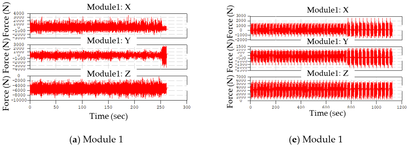
3. Accelerated Triaxial Load Events

A vehicle test was performed to measure the response data from the sedan-type vehicle (2700 cc, Hyundai Motor Company, Seoul, Republic of Korea), and severe distinct events of the test load were adopted at the proving ground (PG) in KATECH. The vehicle test scenario was followed according to the test code developed in KATECH, which is suitable for suspension modules for middle-range vehicles [19,20,21]. The test code was based on the car loading standard (CARLOS), and the CARLOS specification was developed by two institutes (Fraunhofer LBF/Munich, Germany, IABG/Ottobrunn, Germany) and European car manufacturers [22,23]. Representative forces applied to the vehicle suspension module are shown in Figure 1. The candidate test tracks were prepared from specific loads applied in KATECH, and the reaction forces at the wheel center were measured using a wheel force transducer (Michigan Scientific Corp., Charlevoix, MI, USA), as depicted in Figure 1. Three regular event modules and one compensation event module were derived from the combination test tracks in the KATECH PG, as shown in Figure 2. Finally, the specific vehicle test scenarios were determined from the selected four event modules because all event modules were a combination of test tracks in the KATECH PG.
All possible vehicle track tests on the target vehicle were performed, and the four event modules (Figure 3) were derived to evaluate the knuckle part. Because the target knuckle parts were two (the front and rear), the corresponding events were also prepared for two cases: front and rear wheel forces. The four synthesized event modules were computed from the measured wheel forces using the Tecware software (LMS, Leuven, Belgium), as shown in Figure 3.
The four calculated event modules can be used for the accelerated fatigue analysis of suspension module parts so that the synthesized data can be used to assign forces at the wheel center of the knuckle parts.

4. Fatigue Analysis of Knuckle Parts
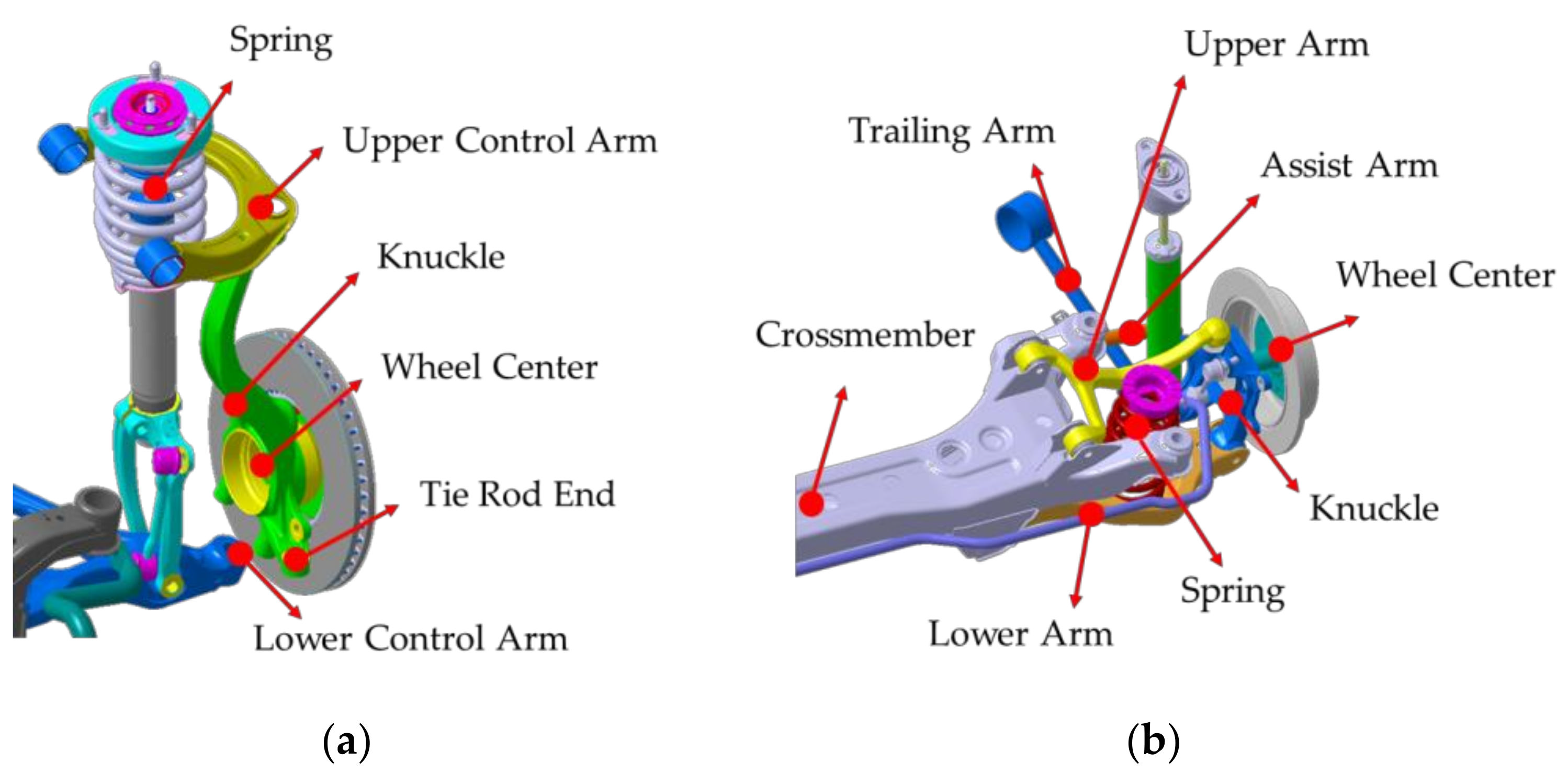
4.1. Analysis Setup

Two knuckles, the front and rear, were considered the target parts for fatigue analysis, and the connecting relationships between adjacent parts were complex. The inserted wheel bearing in the knuckle body connected with the driving wheel, and several arms and links were connected with the knuckle part. The suspension types of the suspension module of the target vehicle are the double-wishbone and multilink, and the connection relationship with the knuckles is shown in Figure 4. A FE model of the two knuckles was established using the commercial software, HyperMesh/Altair, Troy, MI, USA, and a three-dimensional tetra-mesh type was applied to the FE models. The total number of nodes and elements is 14,493, 55,930 for the front knuckle and 38,597, 162,069 for the rear knuckle, respectively. The materials of the two knuckle models were an aluminum alloy, ADC12.
Two options can be applied to clamp them, and the applied force location depends on the clamping conditions. The first option is to clamp all connecting positions with suspension modules, that is, the upper arm, lower arm, and other links, and apply wheel forces on the wheel center. The second is to clamp the wheel center and apply reaction forces on all connecting locations, that is, the upper arm, lower arm, and other links. The accelerated wheel forces were previously measured and processed into four event modules according to the test code in KATECH such that the force input at the wheel center was reliable under the clamping condition with suspension links or arms. In addition, it is challenging to determine the reaction forces at the arms or links in the suspension module, making it difficult to apply the opposite boundary conditions. Therefore, the clamped condition of the adjacent links was chosen as the boundary condition of knuckle part due to the reliable allocation of force information. If the reaction forces at adjacent links can be obtained accurately, it is also possible to apply for the second option by clamping the wheel center position. The applied boundary conditions for the knuckles are shown in Figure 5.

4.2. Analysis Results for Knuckle Parts

Fatigue analysis of the two knuckle models was conducted using Virtual.Lab (Siemens, Germany) to evaluate the built FE models. The boundary conditions were adopted to clamp all degrees of freedom at the adjacent arms, and the assigned three-dimensional translation forces were applied at the wheel center (Figure 5). A preliminary structural analysis was conducted for the unit-force input at the wheel center, and fatigue analysis was performed using the structural analysis results. The fatigue damage was calculated based on the Goodman criterion supported by LMS FALANCS solver and the S-N curve information provided by the supplier. Because hot spots could be identified by the automatic detector supported in software, the specific locations of first four maximum inverse safety factors were figured out automatically. The stress-concentrated locations are shown in Figure 6, and the hottest points are listed in Table 1. The inverse safety factor in Table 1 is the ratio of the calculated stress to the yield stress of the applied material.
Critical plane analysis was performed for the most stress-concentrated location (#1) in both knuckle models, and the most critical planes were 6.4° for the front knuckle and 33.3° for the rear knuckle. Therefore, the similarity force can only be satisfied if the maximum stress occurs at a nearby location and the orientation of the critical plane is similar.

4.3. Uniaxial Load Conditions to Satisfy Severity Similarity

The accelerated uniaxial load conditions were investigated to replace the triaxial load case by satisfying a similar severity, which required similar maximum stress and critical orientation at a nearby location. The two knuckles were simulated using the same FE models, but the boundary conditions differed from those of the triaxial load assignment in Figure 4. If the uniaxial load is applied in the same wheel center, the same stress response will not be expected at the hot points because the two prepared event modules are independent of a directional force. Therefore, the boundary conditions should be changed from the previous triaxial load cases by clamping the wheel force center for the front wheel and clamping several arms with no clamps at the wheel center for the rear knuckle. For the front knuckle, the uniaxial load can be easily applied at the upper arm point owing to the hotspots at nearby locations, as shown in Figure 5. In the case of the rear knuckle, several trials were repeated to select uniaxial load points and other clamping locations. The clamping at the wheel center generated hot points at unexpected locations such that no clamping condition occurred at the wheel center; one arm position was assigned for the uniaxial load, and other adjacent arms were set for clamping locations. Four cases were selected for the modified boundary conditions of the rear knuckle. For example, Case I represents a scenario where the uniaxial load was applied to the lower arm, and the other three arms were constrained as six degrees of freedom. The boundary conditions of the uniaxial load are shown in Figure 7.
The uniaxial load direction was set for six cases of orientations α , β , and γ (Table 2), and sensitivity analysis was conducted over the variations in the direction of unit force. The sensitivity index was set for the angle of critical plane and six cases of unit force were assigned for the calculation of fatigue damage of two knuckle models. The resultant angles of critical plane are presented in Table 2 at the most stress-concentrated location.
The fatigue damage was changed according to the series of triaxial force input, as illustrated in Figure 4, and the angle of critical plane also fluctuated. The target angle of critical plane was determined at the moment when high fatigue damage occurred; 6.4° for the front knuckle and 33.3° for the rear knuckle, respectively. The appropriate direction of the uniaxial load could be determined based on the sensitivity results presented in Table 2. In the case of the front knuckle, the first orientation was set for α = 90 o and β = 90 o , the orientation of γ was increased to 25°, and the orientation of the critical plane was −4.4°. For the rear knuckle, the orientation of the critical plane was 33.2° in the direction of the uniaxial load at α = 90 o , β = 90 o , and γ = 0 o in Case III. The next step was to increase the magnitude of the uniaxial load to the target maximum stress, as listed in Table 1. The final updates in the hotspots are listed in Table 3.
The severity similarity focused on the value of inverse safety at the hotspot, and the second priority was the orientation of the critical plane at the response locations. The maximum stress similarity errors for the front and rear knuckle were 0.02, 0.04 for reverse safety coefficients, and 10.8 and 0.8 degrees for critical plane angles, respectively. The orientation error at the front knuckle was relatively large compared with that of the rear knuckle. However, the value of the inverse safety was consistent for the two knuckle models. Therefore, the proposed uniaxial load cases can replace the original cases under triaxial loads with a sufficiently reliable margin. The final specifications of the uniaxial load information are listed in Table 4.

5. Conclusions

The fatigue analysis of the two knuckle models was conducted for triaxial load cases using the test code developed by KATECH, in which the loads were applied in the center of the wheels. The boundary conditions were determined to clamp all the degrees of freedom at the adjacent arms in the suspension module. The triaxial load cases were derived from the four event modules, and each mode was calculated based on the measured wheel force data of the target middle-range sedan vehicle. The inverse safety factor of each knuckle mode at the hotspot was obtained from the fatigue analysis result: 0.25 for the front knuckle and 1.03 for the rear knuckle. The orientation of the critical plane was determined for each case. The boundary conditions of the accelerated uniaxial load case were different from those of the triaxial case; the load assignment point was set for the upper arm of the front knuckle and the assist arm for the rear knuckle. For the front knuckle, both the wheel center and the lower control arm were fully clamped, all other arm positions were clamped, and the wheel center was ignored for the rear knuckle. The sensitivity analysis of the two knuckle models was conducted over six directional sets of unit loads, and the appropriate orientation of the uniaxial load case was determined based on the sensitivity analysis results. The magnitude of the uniaxial load case was adjusted until the maximum stress value at the hotspot was consistent with the triaxial simulation results. The final specifications of the two knuckle models were selected according to the maximum stress similarity requirement by comparing the stress conditions; the inverse safety factors with 0.02, 0.04 error, and critical plane angles with 10.8, 0.8 degrees error for front and rear knuckles, respectively. Therefore, the proposed uniaxial load specification can sufficiently replace the original triaxial load case according to the maximum stress similarity criterion.

Funding

This research received no external funding.

Data Availability Statement

The data presented in this paper are available upon reasonable request to the corresponding author.

Acknowledgments

This study was supported by the National Research Foundation of Korea (Grant No. 2020R1F1A104860211).

Conflicts of Interest

The author declare no conflict of interest.

References

  1. Nasada, M. Effect on compliance and alignment variation with respect to stiffness of knuckle and absorber in a McPherson struct suspension. Veh. Syst. Dyn. 2006, 44, 171–180. [Google Scholar] [CrossRef]
  2. D’Ippolito, R.; Hack, M.; Donders, S.; Hermans, L.; Tzannetakis, N.; Vandepitte, D. Improving the fatigue life of a vehicle knuckle with a reliability-based design optimization approach. J. Stat. Plan. Inference 2009, 139, 1619–1632. [Google Scholar] [CrossRef]
  3. Jeon, G.T.; Kim, K.Y.; Moon, J.H.; Lee, C.; Kim, W.J.; Kim, S.J. Effect of Al 6061 alloy compositions on mechanical properties of the automotive steering knuckle made by novel casting process. Metals 2018, 8, 857. [Google Scholar] [CrossRef] [Green Version]
  4. Kashyzadeh, K.R.; Souri, K.; Bayat, A.G.; Jabalbarez, R.S.; Ahmad, M. Fatigue life analysis of automotive cast iron knuckle under constant and variable amplitude loading conditions. Appl. Mech. 2022, 3, 517–532. [Google Scholar] [CrossRef]
  5. Wysocki, T.; Chahkar, J.; Gauterin, F. Small changes in vehicle suspension layouts could reduce interior road noise. Vehicles 2020, 2, 18–34. [Google Scholar] [CrossRef] [Green Version]
  6. Kim, J.; Kwon, S.; Ryu, S.; Lee, S.; Jeong, J.; Chung, J. Noise identification for an automotive wheel bearing. Appl. Sci. 2022, 12, 5515. [Google Scholar] [CrossRef]
  7. Reza Kashyzadeh, K.; Farrahi, G.H.; Shariyat, M.; Ahmadian, M.T. Experimental accuracy assessment of various high-cycle fatigue criterion for a critical component with a complicated geometry and multi-input random non-proportional 3D stress components. Eng. Fail. Anal. 2018, 90, 534–553. [Google Scholar] [CrossRef]
  8. Kim, C.J. Accelerated sine-on-random vibration test method of ground vehicle components over conventional single mode excitation. Appl. Sci. 2017, 7, 805. [Google Scholar] [CrossRef] [Green Version]
  9. Kim, C.J.; Kang, Y.J.; Lee, B.H. Generation of driving profile on a multiaxial vibration table for vibration fatigue damage. Mech. Syst. Signal Process. 2012, 26, 244–253. [Google Scholar] [CrossRef]
  10. Kim, C.J.; Kang, Y.J.; Lee, B.H. Experimental spectral damage prediction of a linear elastic system using acceleration response. Mech. Syst. Signal Process. 2011, 25, 2538–2548. [Google Scholar] [CrossRef]
  11. Pawliczek, R.; Rozumek, D. The effect of mean load for S355J0 steel with increased strength. Metals 2020, 10, 209. [Google Scholar] [CrossRef] [Green Version]
  12. Haug, E.J.; Choi, K.K.; Komkov, V. Design Sensitivity Analysis of Structural System; Academic Press: New York, NY, USA, 1986. [Google Scholar]
  13. Haftka, R.T.; Gurdal, Z. Elements of Structural Optimization, 3rd ed.; Kluwer Academic Publishers: Dordrecht, The Netherlands, 1993. [Google Scholar]
  14. Kim, C.J.; Lee, B.H.; Kang, Y.J.; Ahn, H.J. Accuracy enhancement of fatigue damage counting using design sensitivity analysis. J. Sound Vib. 2014, 333, 2971–2982. [Google Scholar] [CrossRef]
  15. Lee, Y.-L.; Barkey, M.; Kang, H.-T. Metal Fatigue Analysis Handbook; Elsevier: Oxford, UK, 2011. [Google Scholar]
  16. Stephens, R.I.; Fatemi, A.; Stephens, R.R.; Fuchs, H.O. Metal Fatigue in Engineering; Wiley Interscience: Singapore, 2001. [Google Scholar]
  17. Findley, W.M. Modified theories of fatigue failure under combined stress. Proc. Soc. Exp. Stress Anal. 1956, 14, 35–46. [Google Scholar]
  18. Shang, D.G.; Sun, G.Q.; Deng, J.; Yan, C.L. Multiaxial fatigue damage parameter and life prediction for medium-carbon steel based on the critical plane approach. Int. J. Fatigue 2006, 29, 2200–2207. [Google Scholar] [CrossRef]
  19. Choi, G.J.; Noh, K.H.; Yoo, Y.M. Real-time dynamic simulation using multibody vehicle model. Trans. Korean Soc. Mech. Eng. 2001, 25, 486–494. [Google Scholar]
  20. Kim, D.; Kim, G.; Chung, I.; Lim, H. Development of durability evaluation technique for semi-active suspension under Chines service condition. In Proceedings of the 2005 KSAE Fall Conference Proceedings, KSAE05-F0260. Anseong-si, Republic of Korea, 24–26 November 2008; pp. 1646–1652. [Google Scholar]
  21. Kim, K.; Kang, W.; Kim, D.; Ko, W.; Lim, J. The durability performance evaluation of automotive components in the virtual testing laboratory. Trans. KSAE 2006, 14, 68–74. [Google Scholar]
  22. Sonsino, C.M. Fatigue testing under variable amplitude loading. Int. J. Fatigue 2007, 29, 1080–1089. [Google Scholar] [CrossRef]
  23. Bellec, E.; Facchinetti, M.L.; Doudard, C.; Galloch, S.; Moyne, S.; Silverstri, M.P. Modelling and identification of fatigue load spectra: Application in the automotive industry. Int. J. Fatigue 2021, 149, 106222. [Google Scholar] [CrossRef]
Figure 1. Measurements of wheel force data for target vehicle using wheel force transducer: (a) Test vehicle at PG; (b) Attached wheel force transducer.
Machines 10 01097 g001
Figure 2. Vehicle test procedure for obtaining four event modules from measured wheel force data.
Machines 10 01097 g002
Figure 3. Computed event modules of target vehicle: (ad) event modules (#1–#4) for front suspension; (eh) event modules (#1–#4) for rear suspension.
Machines 10 01097 g003aMachines 10 01097 g003b
Figure 4. Connection between knuckle parts and adjacent vehicle parts: (a) Front suspension (double-wishbone type); (b) Rear suspension (multilink type).
Machines 10 01097 g004
Figure 5. Boundary conditions of FE model of knuckles for triaxial load conditions: (a) Front; (b) Rear.
Machines 10 01097 g005
Figure 6. Stress-concentrated locations over fatigue analysis of knuckle model: (a) Front (b) Rear.
Machines 10 01097 g006
Figure 7. Boundary conditions of FE model of knuckles for uniaxial load conditions: (a) Front; (b) Rear.
Machines 10 01097 g007
Table 1. Calculated stress values at hotspots for two knuckle models.
Hot PointFront KnuckleRear Knuckle
Inverse Safety FactorInverse Safety Factor
#10.251.03
#20.230.92
#30.230.91
#40.230.88
Table 2. Sensitivity analysis result of knuckle models over different angles of unit force.
Case (°)Front Knuckle (°)Rear Knuckle (°)
α β γ Case ICase IICase IIICase IV
0900−16.723.9−231.426.325.0
900035.223.521.125.726.2
009053.425.820.227.425.2
90900−14.322.829.433.225.5
0909047.722.224.726.125.0
90090−13.824.120.525.926.0
Table 3. Comparison of fatigue analysis results between the triaxial and uniaxial load cases.
Front KnuckleRear Knuckle
Target (Triaxial)Proposed (Uniaxial)TargetProposed
HotspotInv. Safety FactorAngle (°)Inv. Safety FactorAngle (°)Inv. Safety FactorAngle (°)Inv. Safety FactorAngle (°)
#10.256.40.23−4.41.0333.31.0732.5
#20.240.210.921.03
#30.230.210.911.02
Table 4. Final specification of load case for two knuckles.
PartOrientationMagnitude (N)
α β γ
front knuckle9090254598
rear knuckle909004498
Publisher’s Note: MDPI stays neutral with regard to jurisdictional claims in published maps and institutional affiliations.

