1. Introduction
Aggressive global competition, changing customer demands, and innovation in technology are triggering unprecedented and unexpected changes in the market. The manufacturing lead time has now become the bottleneck to achieving a rapid and economic response to change. The current systems engineering approach still follows a classical rigid sequential model [
1] and uses an ad hoc collection of poorly integrated tools and mechanisms to take customer requirements and translate them into the desired system. This yields delays and significantly affects the project lead time and product delivery to the customers [
2]. To overcome this challenge, the concept of a digital factory has become popular within different areas of industry to improve the production phases and deliver products to customers more quickly. The scope of the digital factory is the digitalisation of product models and their integration into the manufacturing process chain [
3]. This starts with the creation of products and system components in a virtual engineering (VE) environment, then using virtual commissioning (VC) in the following stages. From this perspective, VC is regarded as one of the core elements of Industry 4.0 [
4] that offers the following benefits [
5]:
- -
More efficient programmable logical controllers (PLC) programmes;
- -
Accelerated production ramp-ups;
- -
Increased maturity of the software and hardware by the beginning of production;
- -
Operator training before starting production;
- -
A better availability of the manufacturing system when the production is running;
- -
An efficient integration of the processes.
In this vein, Silva et al. [
6] describe digital factories, product lifecycle management and virtual commissioning as three paths that go in parallel with functional interactions between each other. Further, Tomiyama et al [
7] equalises “digital engineering” and “virtual engineering” and regards the “digital twin” (DT) as the link between digital manufacturing and digital engineering. The logic behind this is that the connection between the “cyber” and “physical” parts of the system is achieved by building a DT. On the other hand, the research stream of Industry 4.0 and reconfigurability needs further exploration [
8] due to the freshness of Industry 4.0. Consequently, digital technologies such as simulation, emulation, augmented reality and horizontal/vertical integration possess a great potential for system development. Transferring this fact to the lifecycle scene, VE and VC can cover different lifecycle stages and offer valuable reconfigurability support.
There are a number of tools, techniques and methods that provide VE and VC. These tools use different approaches for system development such as modular-based integration and state-transition diagrams (STD) to describe process behaviour or the digital twin of the real drives and actuators to execute the simulation process. One main objective of this paper is to analyse the current VE and VC execution methods and development and then to construct a systematic methodology of virtually commissioning industrial stations based on an industrial project in the University of Warwick. The creation of a DT that supports the system’s reconfigurability is also illustrated. This methodology prioritises the end user needs, and its novelty lies in controlling the level of detail in simulation to an extent that is sufficient to the end user’s requirements.
The remainder of the paper is structured as follows:
Section 2 reviews the literature of VE and VC contributions to lifecycle support and reconfigurability in addition to the documented approaches.
Section 3 explains the procedure of VC within the context of a digital factory and the end user needs. A methodology to accomplish VC considering these needs is introduced in
Section 4. Afterwards,
Section 5 showcases the application of the proposed methodology. Finally,
Section 6 concludes the paper.
2. Literature Review
Harrison et al. [
9] realised VE’s capability to support the design, configuration and reconfiguration of the system prior to the physical build, which has a significant impact on the design and resources reuse. In addition to the economic impact, Haq et al. [
10] pointed out that the traditional sequential approaches influence quality due to the limited capability of change impact evolution; therefore, a proactive approach in terms of knowledge transfer, virtual integration and commissioning would save process management efforts. Further support of design in the form of fault diagnosis and fault location visualisation was presented in [
11] considering the component-based design approach, which provides a reduction in development and reconfiguration time. In the build phase of the lifecycle, Konstantinov et al. [
12] presented a mechanism by which the elements of various systems can be integrated into a common VE model aiming at increased reconfigurability by means of the created cyber-physical system (CPS). A process-product-resource (PPR) framework was introduced in [
13] to support the reconfiguration using a VE toolset that bridges the three domains’ information exchange. In parallel with all the aforementioned efforts and in the context of the ARTEMIS project, VE is regarded as the main CPS design technology that is expected to reduce cost and escalate quality [
14].
With a focus on VC, Walla and Kiefer [
5] recognised VC as an essential technology when integrating new processes of producing a new product, where VC takes place before the ramp up stage of the lifecycle. Oppelt and Urbas [
15] considered virtual commissioning to not be a procedure that precedes physical commissioning in the system lifecycle but rather a continuous engineering workflow that supports the automation engineer. To examine the simulation prospects across lifecycle phases, Oppelt et al. [
16,
17] accomplished a survey, whose results show that virtual commissioning might be utilised in the detailed engineering, installation/construction and commissioning stages of the lifecycle. Syberfeldt [
18] proposed a four-step holistic solution that would enable virtual commissioning implementation in all lifecycle stages, which facilitates changing the production set-up in terms of lead time and cost minimisation. Additionally, from a lifecycle perspective, Hofmann et al. [
19] highlighted the advantages of VC in terms of time saving through less sophisticated configurations and independence from hardware availability.
Reconfiguration involves both hardware and software changes, and the latter ones affect different control levels, including the PLC [
20]. PLC device management is currently separated from mechanical, process and layout design, and this is attributed to the inability to update the engineering datasets following commissioning, for example [
21]. VC is used for PLC code verification as an automation solution [
22]. Ref. [
22] introduced some futuristic applications of VC in smart grids, human-robot interactions and special machine construction (SMC). When doing so, the most challenging step is the model creation. Makris et al. [
23] recommended the use of virtual commissioning to validate industrial operations behaviour and stated that the benefits include a significant reduction in ramp-up time in addition to further improvement of the equipment reconfigurability. However, the signals mapping between the behaviour model and the 3D CAD model was accomplished manually, which requires a great effort. An Industry 4.0 learning factory lab was established in [
24], where VC helped to reveal the reconfiguration potential by testing various scenarios such as new products and new production sequences. This work shows the need for VC learning labs due to a lack of necessary competence and experience. Vermaak and Niemann [
25] believe that VC allows the system developer to demonstrate the functionality and operation of the system prior to its actual physical build, which means an opportunity to integrate changes and modifications.
Component manufactures are able to offer an accurate model of the component in the form of functional mockup units (FMU) [
26]. Ahrens et al. [
27] introduced an approach based on mechatronic component development. Additionally, from the mechatronic model perspective and to enable VC common model creation, Dietz et al. [
28] suggested the use of a standardised library, PLCopenXML. Nevertheless, once the vendor modifies the model, the behaviour should be changed manually. To design adaptive manufacturing and in the vision of mechatronic system design, VC was used in [
29] to evaluate different solutions based on the interaction between different systems using the Tecnomatix software toolkit from Siemens. However, the mechanism by which VC and VE are related in the proposed architecture could be further detailed. Furthermore, using the mechatronic components increases the complexity and decreases the end user’s usability.
Form a VE perspective, Shafiq et al. [
30] indicated that VE provides an interface that can empower the end user’s ability to configure the final product. Therefore, the level of detail should be moderated to a satisfactory level for both the end user and the machine builder. The end user should be able to visualise, verify and validate the intended manufacturing process. On the other hand, the machine builder needs functional models with a high level of details. When it comes to reconditioning machines and retrofitting, Ayani et al. [
31] recommended the use of emulation tools to create DT of the old machine, despite the fact that the typical use of emulation is in the development and validation stages of the system lifecycle. In this approach, a DT is created in the engineering and development phases, then virtual commissioning follows in the commissioning and validation phases. An advantage of this approach is the use of Simumatik3D, which is free of charge. For testing legacy systems that suffer from a lack of documentation, Khan et al. [
32] suggest a model-based approach that utilises a software (Sequence Planner) responsible for the initiation of a specification model which is improved to be used for DT creation and VC.
Hauf et al. [
33] take into account the cost of creating the DT in terms of software licence, hardware training and personal costs; however, they do not anticipate any extra costs after VC is implemented. Additionally, the introduced setup lacks a common information exchange format between the “PLC/Process chart” and the “control programme”, as they do not necessarily use the same information format. With more quantification, the experimental work in [
34] resulted in a decrease in the debugging time by 73% for a small project; however, the time consumed to create the virtual twin was not considered. Orive et al. [
35] introduced a methodology of testing the control system in the VC phase with a focus on DT behaviour when faults take place. They also briefly showed the DT construction vision.
To summarise, it has been shown in the literature review that VE and VC offer significant support in the design phase. This is clear in terms of system component engineering to adapt to the changes in capacity and product variety demands. With the current trend toward the digitalisation of products and manufacturing processes, there is a need to systematise the creation of the cyber-physical system and its corresponding DT. The following gaps can be noticed in the presented literature work above:
- •
The recent trend is to accompany VC with DT along with different lifecycle phases;
- •
The creation of a DT suitable for VC was not given enough attention, and model creation, in general, should be systematised, as it needs time and effort;
- •
The mechanism of digital twin reconfigurability and VC in the field of assembly needs further investigation;
- •
The accomplishment of VC sometimes involves the use of multiple tools, i.e., for CAD and behaviour, and sometimes it is limited to one tool;
- •
There is no approach aiming at facilitating the VC application for the end user.
This paper constructs a road map of VC implementation based on a review of the existing tools and by means of a developed toolset. To describe the VC model behaviour, state transition diagrams (STD) and (in .json) behaviour are used. This allows a quick modelling of the virtual model with basic timings and complexity of the model. This helps overcome the challenges of digital twin establishment as the introduced map considers different phases of the manufacturing system lifecycle.
The audience this paper addresses is manufacturing systems builders/developers, in addition to the researchers in the area of factory digitalisation. The proposed setup is applicable if the project customer/system integrator is willing to develop a DT of the machine where CAD, timing, and other data are provided by a machine builder. In this case, the machine builder should provide timing diagrams; then, the customer integrates the machine to its layout with other machines, systems, operators, and tests it with a PLC setup. For this use case, the precise mechatronic behaviour of the virtual system is not always needed.
4. Methodology
4.1. The Objectives and Area of Focus
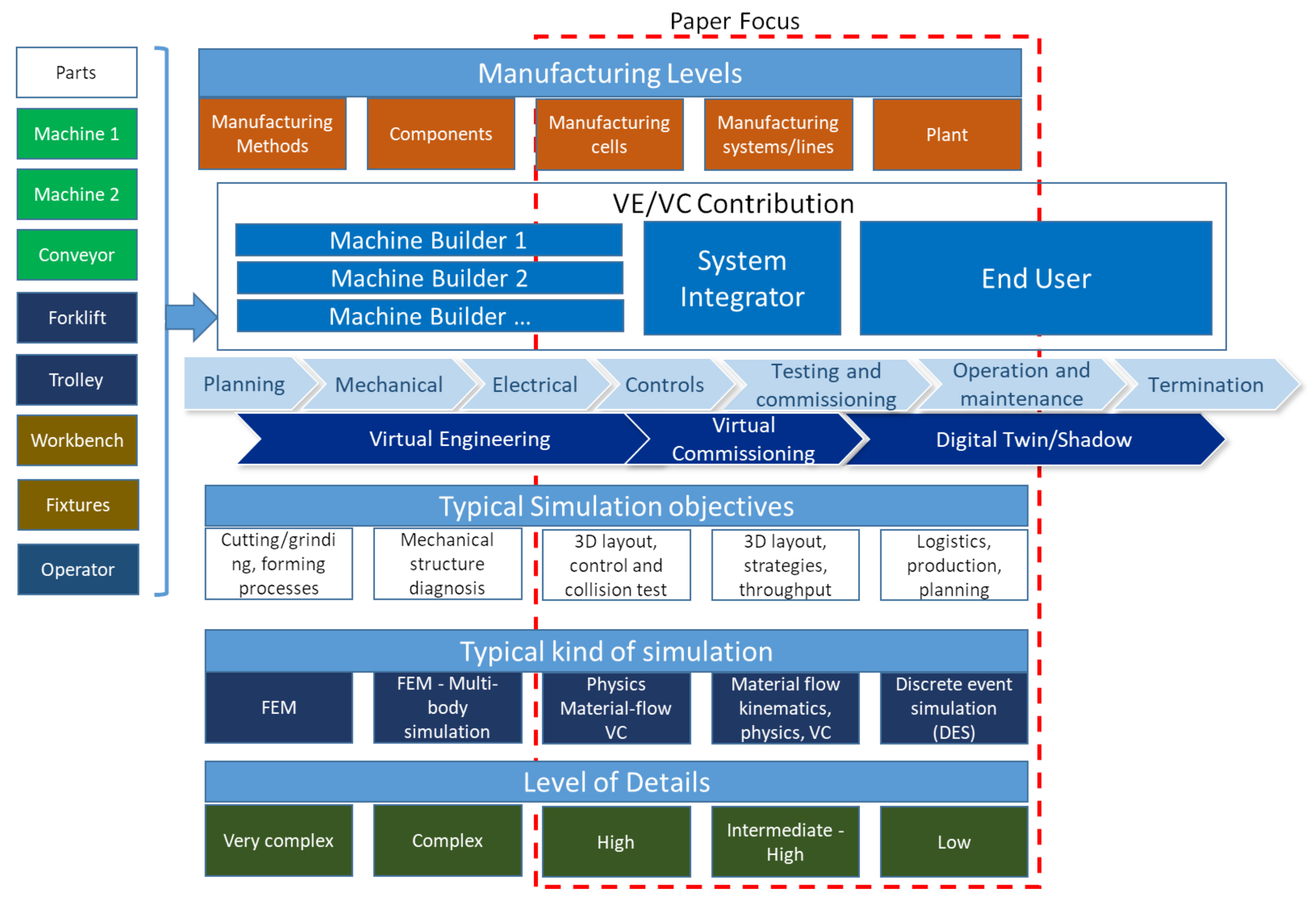
A manufacturing system lifecycle consists of several stages where VE and VC can be used to shorten the overall time-to-market and facilitate delivering the objectives of each stage. In the course of development across lifecycle stages, three stakeholders are recognised: the machine builder, system integrator and end user.
Figure 1 shows the deployment of VE and VC by these three stakeholders across the process of system development. Although all stakeholders are involved in the development, their contributions to VE and VC process differ, as shown in
Figure 1. Therefore, the level of simulation details and objectives vary for each of them. For the end user or system integrator, there is no need to produce highly detailed, complex simulations of physical objects and materials (for process planning). Their objectives are cycle time and tact time setting, layout planning, safety and ergonomics evaluation and integrating different systems in one layout. This includes simulating, testing and implementing different scenarios that combine machines, conveyors, manual operations, transportation and logistics activities in the same layout.
On the other hand, the machine builder’s interest is to precisely understand the machine behaviour and to comply with the customer’s requirements. Therefore, during VE/VC, it is aimed to simulate/emulate each component and the machine behaviour as accurately as possible.
Figure 1 shows the machine builder’s scope in terms of manufacturing levels, typical simulation objectives, types of simulation and the corresponding level of details.
The current work sheds light on the system integrator/end user needs fulfilment. It is assumed that the machine builders provide CAD, timings, and other information according to RFQs (request for quotations) and previous simulation and virtual build results. Then, the system integrator/end user directly uses this information for the layout simulation and virtual commissioning. As a result, these activities can be implemented at two levels of detail (LOD): complex (machine builders) and intermediate (system integrator/end user).
Decreasing the level of detail is intended to grant the end user more flexibility. The critical processes can be simulated without building complex mechatronic systems. This leads to time and effort savings and less need for skills. Further, it is possible to simulate all types of the components in a single layout, including human and extract data such as ergonomics, MODAPTs timings, possible clashes and safety warnings. Consequently, this approach allows detailed auto and semi-auto station simulation and emulation.
The communication and collaboration between stakeholders at all stages take place with the help of virtual engineering tools that provide the visualisation and testing of the concept and design. To seamlessly transfer the virtual model between different departments and stakeholders, the models’ behaviour and simulation aspects should be understandable without extra necessary skills. For example, the designer and planning specialist creating simulations can “speak the same language” as automation specialists. Translating this into technical practices, simulation models (built by the system integrator or machine builder) can be easily connected to PLC without extra effort from the automation engineers to execute VC.
If VE and VC tools are being used from the initial concept phase through the project, the digital twin of the physical station or cell/line can be created. It further can be part of a digital factory as the virtual model can be used as a CPS or digital twin/shadow during the operation phase.
4.2. Digital Twin Capabilities
The digital twin is regarded as a prerequisite of the CPS, where DT is the digital aspect of the CPS [
57]. According to the Industrial Internet Consortium (IIC) [
58], the digital twin should have the following features:
Document management: this includes the drawings and instructions throughout the lifecycle;
Model: a suitable digital representation that mirrors the properties and behaviour;
Simulation: a representation of the physical device in a simulation environment;
Data Model: a standardised data model for connectivity, analytics, and/or visualisation;
Visualisation: a graphical representation of the object;
Model synchronisation: the alignment of the model with real-world parameters;
Connected analytics: the algorithms and computational outcomes.
To achieve this, the next section describes the utilised apparatus.
4.3. Apparatus
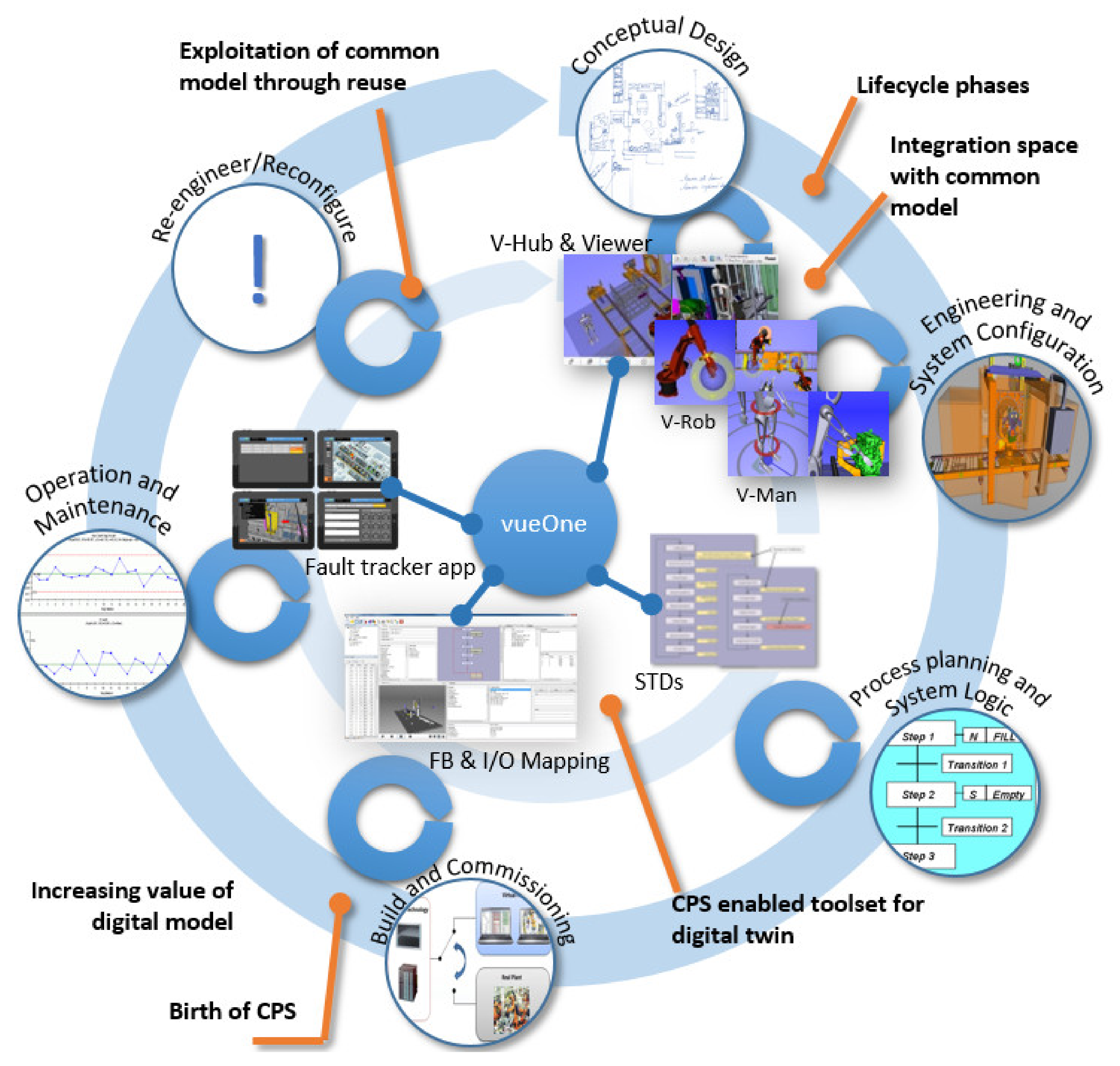
Layout simulation is intended to be in a 3D representation with necessary complexity but not require extra effort and time for development (it is to be done before the machine build). For this reason, the vueOne toolset was used. This toolset allows machine, logistics and operator testing at one layout with the use of STDs for the simulation development without extra effort. As timing (assuming here acceleration/deceleration, physics, types of actuator, etc. are not important) was already provided by the machine builder, the main sequence and fit of the machines and other facilities into the layout and the interaction with other stations needed to be emulated and tested.
The VE software package “vueOne” can support the manufacturing system lifecycle, as shown in
Figure 2. vueOne is a component-based software toolset developed by the Automation Systems Group (ASG) of the University of Warwick. The software provides static and dynamic component creation from .wrl files and further virtual automation system development from these components. The software toolset also includes a free viewer to share models and simulations during different phases of the project lifecycle for effective communication at all levels of the business and across the supply chain.
Figure 2 shows the virtual toolset “vueOne” supporting all stages of automation system lifecycle development. The viewer can be used by the end user, where it is possible to manipulate the simulation, components, timing diagrams, MODAPTS and other parameters.
4.4. Requirements and Activities for Virtual Commissioning
The commissioning of the manufacturing system requires testing its physical setup along with the validation of low- and high-level software programmes. Most of the commissioning time is consumed in the software debugging [
20]. Usually, assembling, testing and commissioning of the physical machine is done at the machine builder site, where the general functionalities are tested along with the mechanics, electrics and software interactions. After these tests, the machine builder moves the system to the customer’s site to assemble and integrate it into its facility. There, the machine is to be tested and validated against the plant owner’s specifications [
39].
The simulation model must be ready for the virtual commissioning process, so some pre-commissioning activities are to be done. The whole VC process can be split in several phases:
Documentation preparation and validation: e.g., machine timing calculations, electrical drawings, wiring diagrams and the Factory Acceptance Test (FAT) procedure;
Virtual software readiness validation: in terms of the proper behaviour of the system components, PLC IO mapping, the proper safety and the communication architecture;
Commissioning of the virtual model: during this procedure, the virtual model is to represent all the required production processes, capacities, with the all necessary parts. Different scenarios are to be emulated, including potential errors, faults, safety cases;
Final validation documentation and necessary model changes.
After the completion of virtual commissioning, the final design and process validation, the physical machine is to be built. The next step is to execute the physical commissioning at the machine builder site and at the end user site afterwards. The virtual model must also be validated against the physical one (timings, processes, ergonomics, etc.). If there are some errors or mistakes in the process or timing differences between the physical machine and the simulation, it is necessary to define the cause of the problem.
In the next section, a case study that exemplifies the proposed methodology is introduced.
5. Case Study: VE and VC of Vertical Assembly Station
To demonstrate the application of the methodology proposed in the previous section, a case study based on an industrial project is presented.
5.1. Description
The Automation Systems team from WMG, the University of Warwick took part in the HVEMS (High Volume E-Machine Supply) project from the UK providing VE to the manufacturing stations. This project aimed to create “make-like-production” (MLP) facility for the investigation of manufacturing and assembly methods for electric motor production [
59]. The vueOne toolset was chosen to support virtual engineering and simulations of the MLP stations across all phases of the stations’ lifecycles. The case study presents the implementation of VE and VC of the MLP stations on a vertical assembly machine. The case study presents a layout of the vertical assembly press, which assembles electric motor’s rotors. The VE and VC were done by the system integrator and CAD, and the timing details were provided by machine builders (press, lift assist). The main objectives of the VE/VC were:
To test the assembly station at early stages of the project when the design, process and layout of the station are not clear and verify them at virtual build events;
To verify if the cell works properly with all machines and to make sure that lift assist and operator ergonomics and safety are as in the real-world environment by using VC;
To test if the level of details is satisfactory for the end user’s requirements;
To compare the virtual and physical system, analyse the difference (in timing, layout, auto/semi-/manual processes). Then, to identify the cause of difference and apply necessary changes in the virtual model or the physical station. Finally, to calibrate the virtual model or physical machine accordingly;
To use the virtual model for the further lifecycle stages: digital shadow/digital twin during the operation and termination/reconfiguration phases (such as monitoring, maintenance and change).
5.2. Virtual Engineering of the HVEMS Station Using vueOne
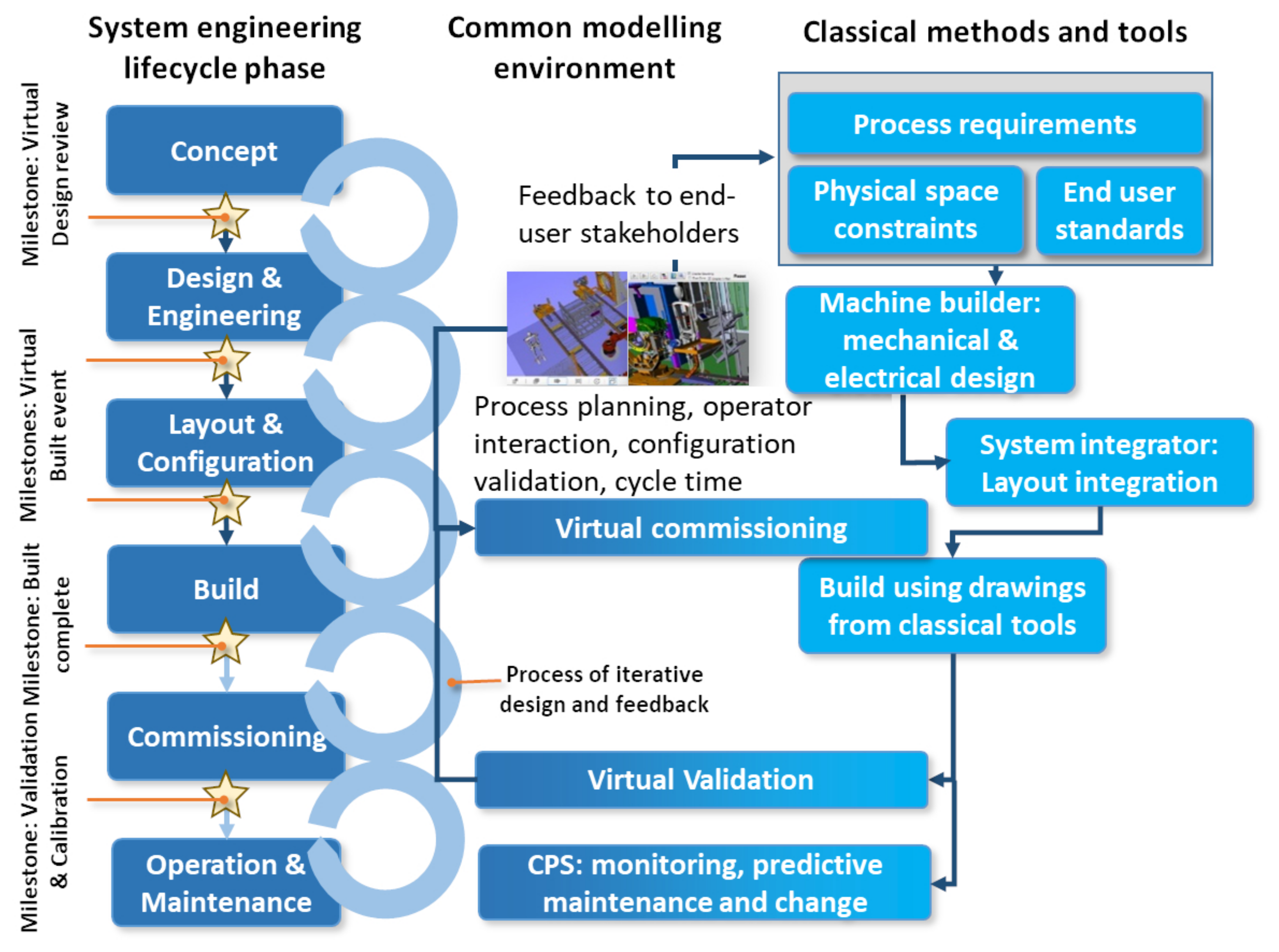
Figure 3 describes the use of the vueOne VE toolset within the context of the case study. To support the development of each station from the concept phase to the final production stage, the following aspects should be identified: station deliverables, end user requirements and standards for ergonomics, health and safety, and the design and assembly process. For this reason, a “Virtual Design Review” and “Virtual Build” events with all the partners involved in the design and engineering were conducted. In the “Virtual Build” events, the initial engineering process started with brainstorming meetings with the machine builders, system integrators, researchers and end users to define the aforementioned aspects. This was accompanied by the visualisation of the station processes, planned station layout and intended integration with other MLP processes and stations, cycle timing calculations and potential errors and threads. The design and functionality were continuously reviewed and tested virtually using the vueOne toolset. An example of the deliverables is the modelling of human operator activities using the V-man module with the further ergonomics, health and safety analysis. As a result, the concluded information constitutes the basis to reach the design frozen and build phases to initiate the machine design.
Once the final machine specifications, station layout and configuration were defined, the frozen design milestone was reached and the build process was started. The virtual simulation support continued in this stage in terms of process improvement and further necessary changes until the commissioning phase. The virtual commissioning was executed in parallel with the build phase when PLC, HMI and PCU (press control unit) hardware configurations and software programmes were defined and ready for the tests.
After building the machine and testing it, the simulation of the processes was compared against the physical machine performance for the final validation. The difference was analysed to allocate the misidentified variables whether on the physical machine/operator side or the modelling/simulation side. After the commissioning, the virtual model was further used as a digital twin/shadow to monitor the processes and for the virtual reflection of physical parts of the machine as a predictive maintenance tool, e.g., to calculate a number of cycles of a safety door’s pneumatic cylinders to inform the administrator when maintenance is needed. This digital twin can also be used if any changes in product/process are detected. These changes can be tested in the virtual model of the machine and the whole virtual layout (or digital factory). In another scenario, the digital twin of the machine with necessary changes can be connected to a physical PLC during its working to test the virtual changes in a real working environment. Then, we can apply the changes to the physical machine.
The virtual model was created, analysed and changed in each stage in parallel with the machine development by the milestones (
Figure 3). Milestone results were presented and brainstormed at virtual design reviews and virtual build events with all partners and stakeholder’s representatives. The main objective was to test the physical station before it was built using the virtual model with minimum time and effort (as low as possible while being as precise as possible). By excluding a high level of details, it was possible to achieve the objectives and end user requirements.
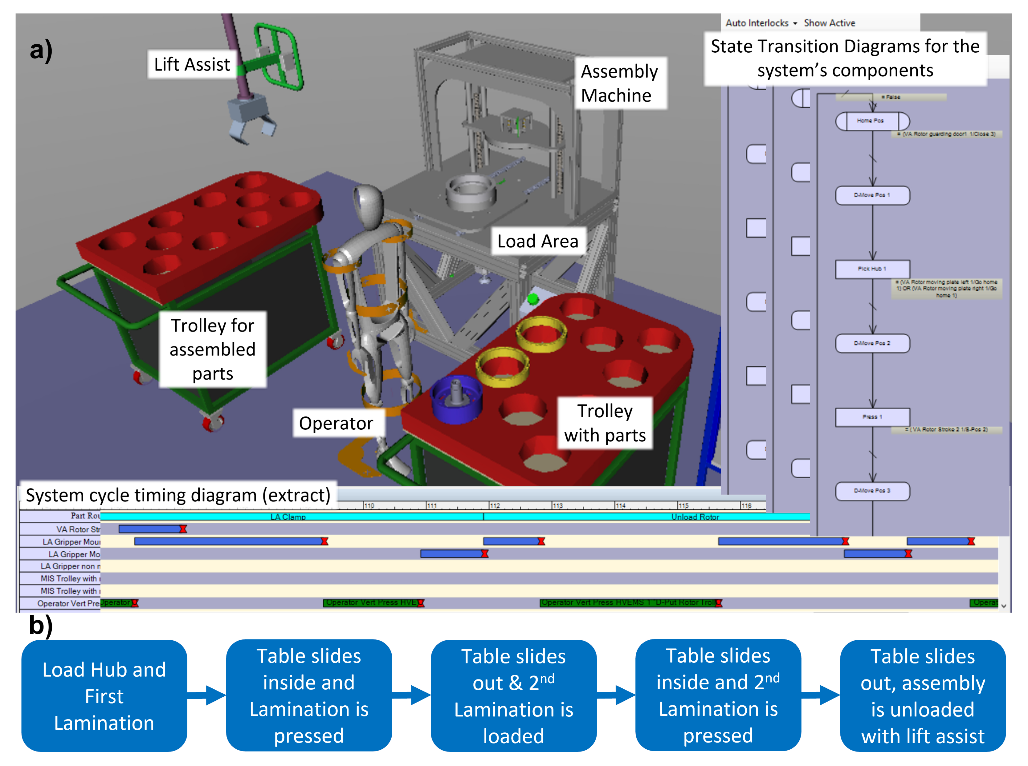
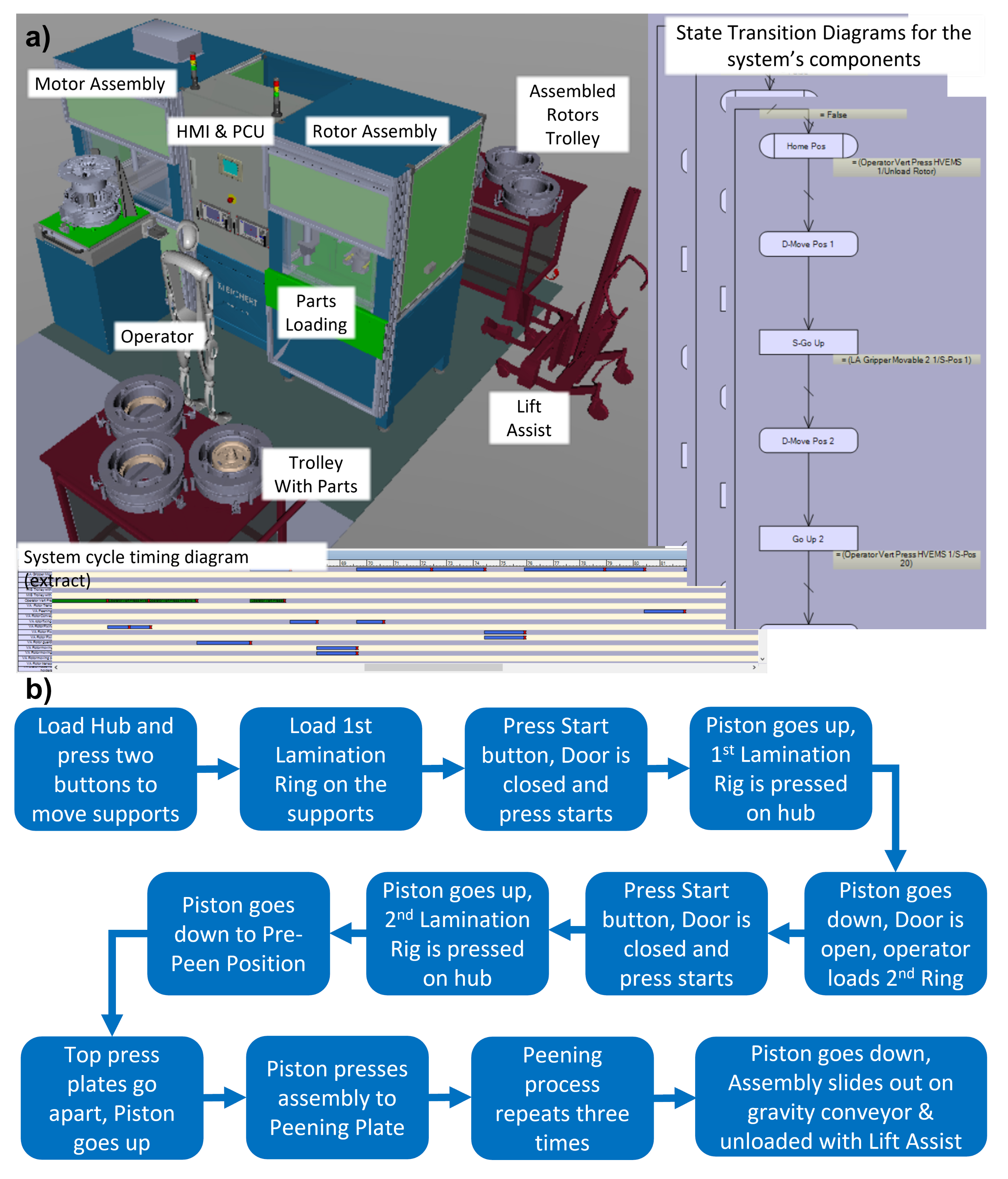
The task of the vertical assembly station involves assembling rotor hubs with two lamination rings and fixing them on the hub with twelve peens. The initial design of the vertical assembly station is shown in
Figure 4a. In the initial phase, the draft virtual model and simulation were created. The station model consisted of the following main components: the vertical assembly machine, loading and unloading trolleys, lift assist and the operator area. The behaviour of the station is represented by means of STDs on the right-hand side of the
Figure 4a. Each component has its own STD with static states for the position, dynamic states for the movement parameters and execution conditions. The components interact with each other based on their behaviour and the execution conditions.
The station conceptual process is shown in
Figure 4b. During the initial design review and the following upgrade of the station, the final design and assembly processes were changed; the peening mechanism was also modified, and extra guarding was added, as well as the colour detection and unloading conveyor. Finally, the machine design enabled it to perform two functions: rotor assembly and final motor assembly. However, as the rotor assembly has separate main functionality function blocks, the decision was made to execute VC only for the rotor assembly process.
Following the design changes and extra activities/functions added during the development process of the station, and to increase the accuracy of the simulated process in the virtual model final design, the number of operation steps were increased, which led to an increase in the overall cycle time. The system cycle timing diagrams were generated automatically through the vueOne logic engine by aggregating STDs of the system’s components. These timing diagrams can be noticed at the bottom of
Figure 4a and
Figure 5a. It should be mentioned that after these changes, the simulated vertical assembly process time was still within the initial end user requirements.
The process of the rotor assembly is shown in
Figure 5b. The station assembles the rotor using the following sequence of operations:
The operator loads the hub and first lamination ring from the trolley to the machine;
The machine presses the lamination ring onto the hub;
The operator loads the second ring to be pressed;
After pressing both lamination rings, an automatic peening operation starts to fix laminations and the hub.
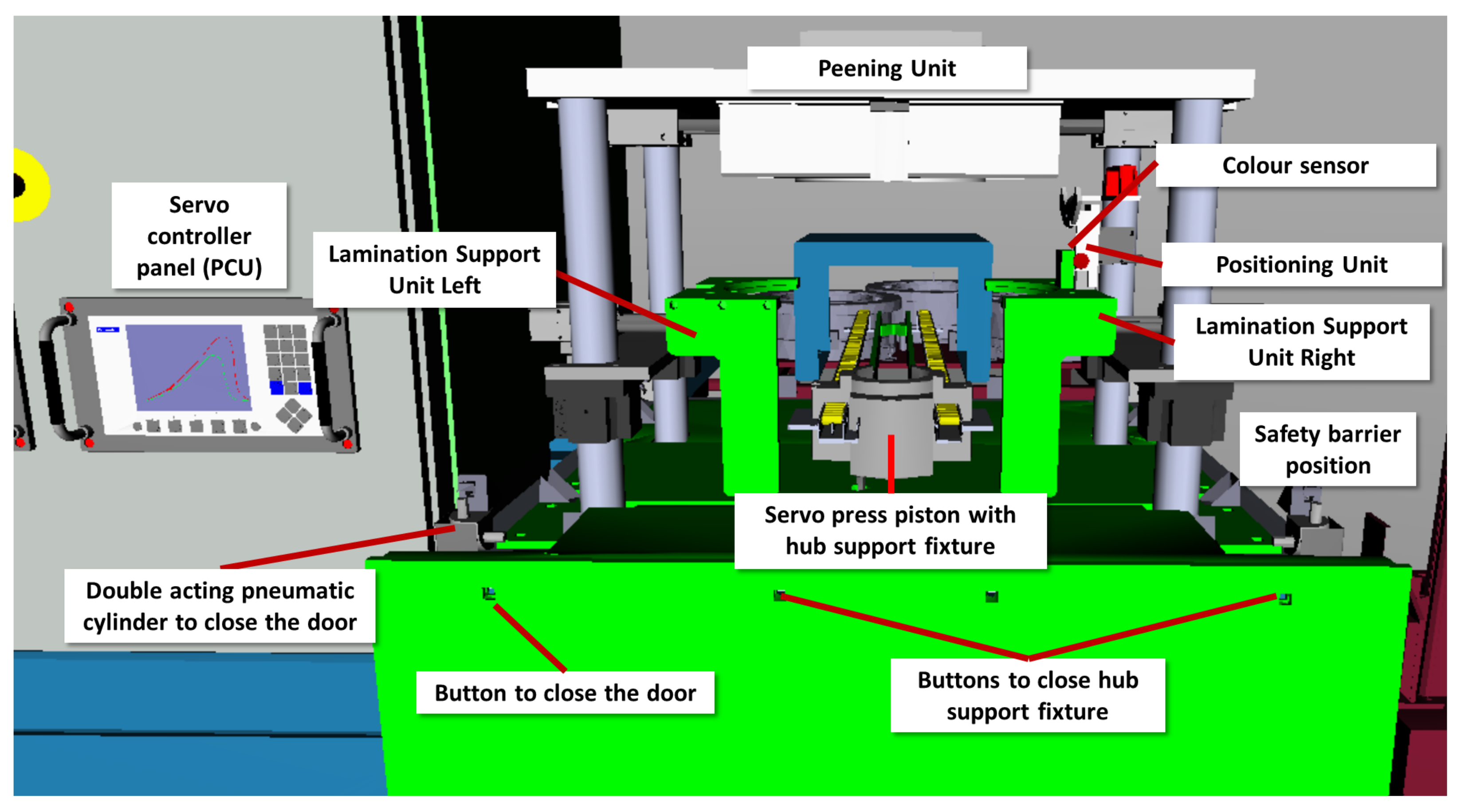
After that, the assembled part slides out from the machine, and the operator unloads it at the trolley with a lift assist. The simulation model (see
Figure 6) was made from virtual static components (such as the frame, guarding, human machine interface (HMI), etc.) and dynamic components representing actuators (such as the servo drive piston, support units, safety door, positioning unit, etc.). Manual loading and unloading of the parts were executed with a virtual manikin. The virtual simulation was presented to the partners and analysed at Virtual Build Evens during the project. It was done simultaneously with the physical system development to improve the design and process stages.
5.3. Station Architecture for Virtual Commissioning
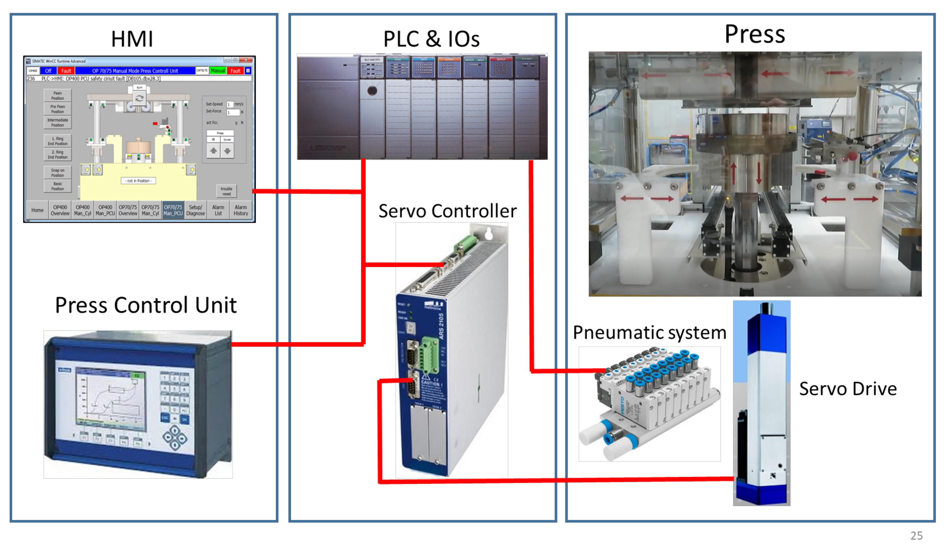
The VC of the vertical assembly station was executed to verify the PLC code against the machine functionality.
Figure 7 shows the physical architecture of the station which consists of:
- •
HMI—executes the machine programmes;
- •
Press control unit (PCU)—controls the pressing process parameters;
- •
PLC—general machine logic;
- •
Servo drive—physical execution of the pressing process operated by the servo controller;
- •
Pneumatic system—general machine functionality (safety door, support units, peening plate movement, etc.)
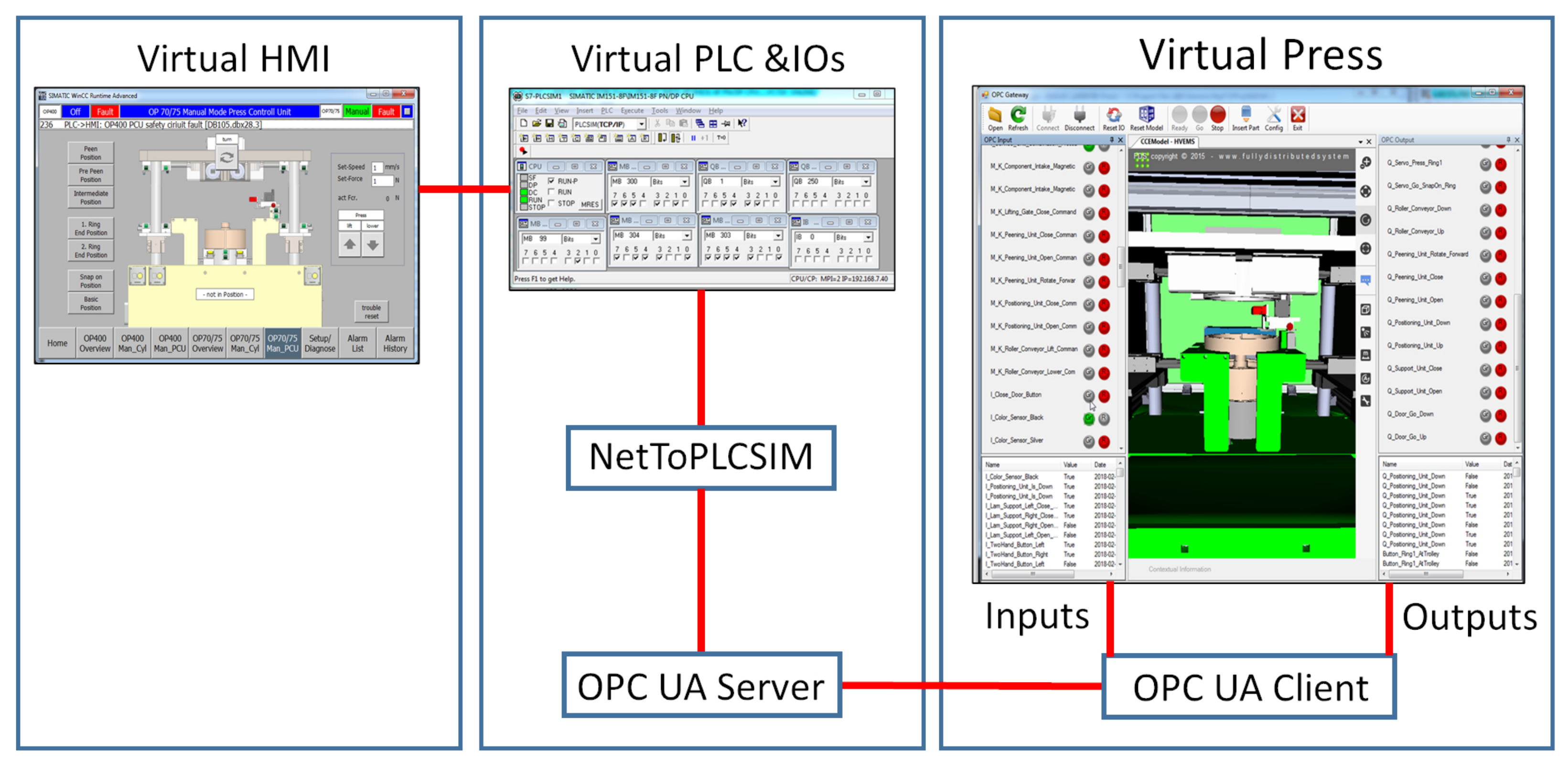
Figure 8 shows the virtual installation where the virtual PLC and HMI are connected to the OPC UA server via the NetToPLCSim application. The OPC UA server has a client that is embedded into the virtual machine to transfer signals between the cyber machine and PLC. The vueOne OPC Gateway is a VC application which animates the behaviour of the vertical assembly machine being driven by the virtual PLC via the described architecture. Each component has its own behaviour and conditions to communicate with the IOs of the PLC, which further drives the virtual simulation according to the PLC code. The components’ behaviour table with “Q” as a PLC output will be triggered by PLC inputs “I” as an outcome of the completed action.
5.4. Servo Signal Mapping and Changes in PLC Code
The encoder of the servo drive sends signals to the servo controller, regularly reporting the motor shaft position. The PLC and servo controller exchange commands to control the drive shaft position, the programme being executed and the pressing parameters. The virtual piston moves continuously and sends positioning signals to the PLC. This requires mapping all signals to the communication PLC servo controller. Of note, the 3D graphics of the vueOne tool had to be improved along with the new component type creation, with each signal behaviour definition.
After creating a table of all components’ requirements, it was necessary to modify the PLC code. It is not possible to trigger physical inputs directly via OPC UA from the simulation model; therefore, it was necessary to change the PLC code to use the memory of the PLC processor. Therefore, each physical input was duplicated with the memory address. Additionally, the “Switch VC” switch function was added to each network where physical input was used for further virtual or physical machine working modes.
5.5. Components Behaviour, Link Points Shift and IOs Description
All the inputs and outputs, behaviours, and link point shifts used in the virtual model needed to be manually scripted in a Json-format file. The Json file tag addresses have to be the same as the OPC UA server addresses. The IO tag names will appear at the OPC Gateway VC application. The predetermined values with their types (e.g., Boolean, Byte, Integer, etc.) are to be defined in the file to be used as default values in the VC application during the operation.
The component ID was taken from the .xml file of the simulation along with position and speed. The behaviour actions started with the input conditions being true (e.g., output Q_Door_Go_Up was triggered). Each action consisted of a start/end position and time. When the action was completed, the outputs became true/false.
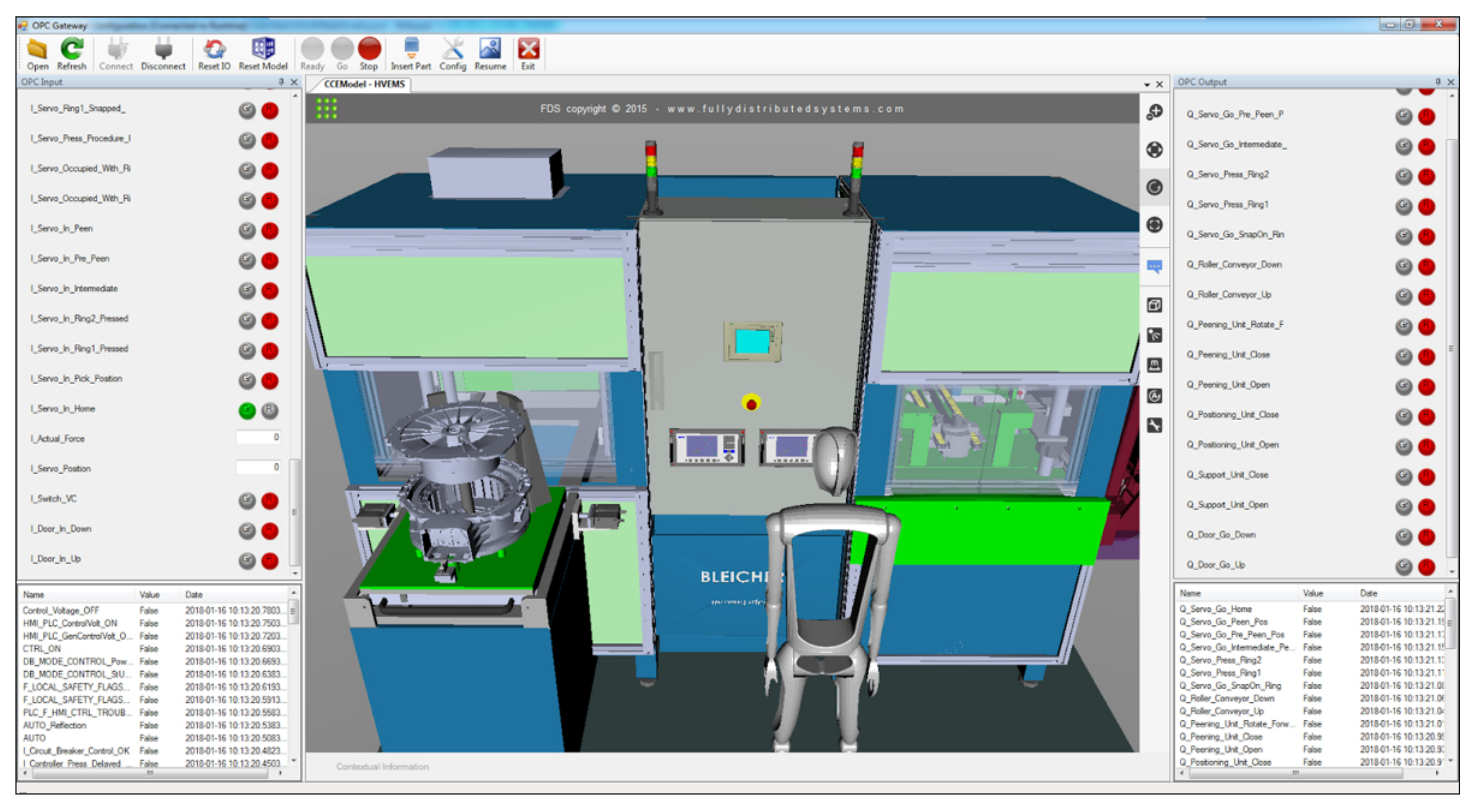
5.6. Virtual Commissioning Execution
The vueOne OPC Gateway visually represents the machine working (
Figure 9). Its functionality and interface were improved during the case study. The operator can test the machine functionality via the tool interface in manual/auto mode and monitor the process, clashes and sequence. Some IOs need to be predetermined or triggered manually via the VC application, such as safety or servo parameters.
The machine assembly cycle was tested and validated according to the process sequence in manual and auto modes. Possible errors and safety functions were also tested, such as triggering an optical sensor failure, the wrong orientation of the lamination rings, triggering the appropriate safety light enclosure, clashes, two-handed push buttons not pressed at the same time, etc.
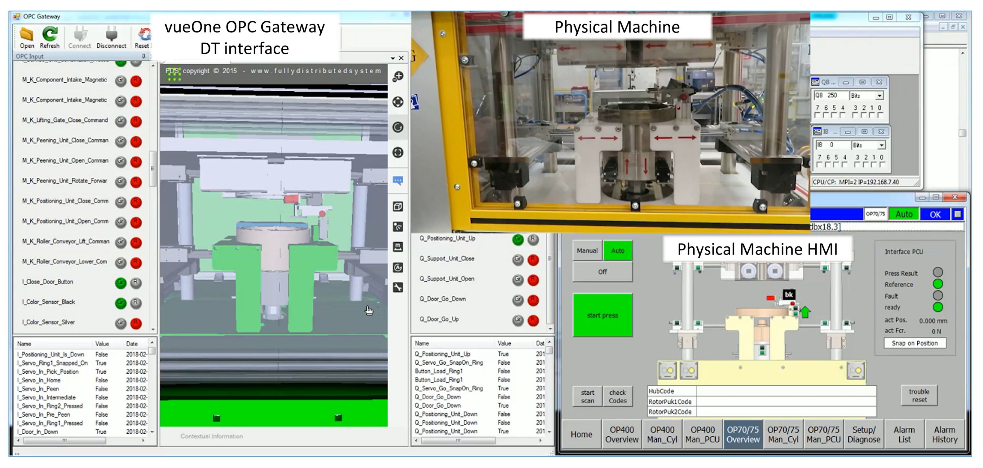
Figure 10 shows the interface of the vueOne digital twin connected to the machine’s PLC via the OPC UA interface during the lamination pressing operation. It also shows the HMI interface where the operator sends the control commands, both of which are going to the DT and the machine. The DT mimics the machine working sequence and collects the data to store in a database. The next connected analytics DT modules (such as the fault tracker application, KPI analytics, etc.) will be integrated into the proposed framework during future work.
5.7. Results
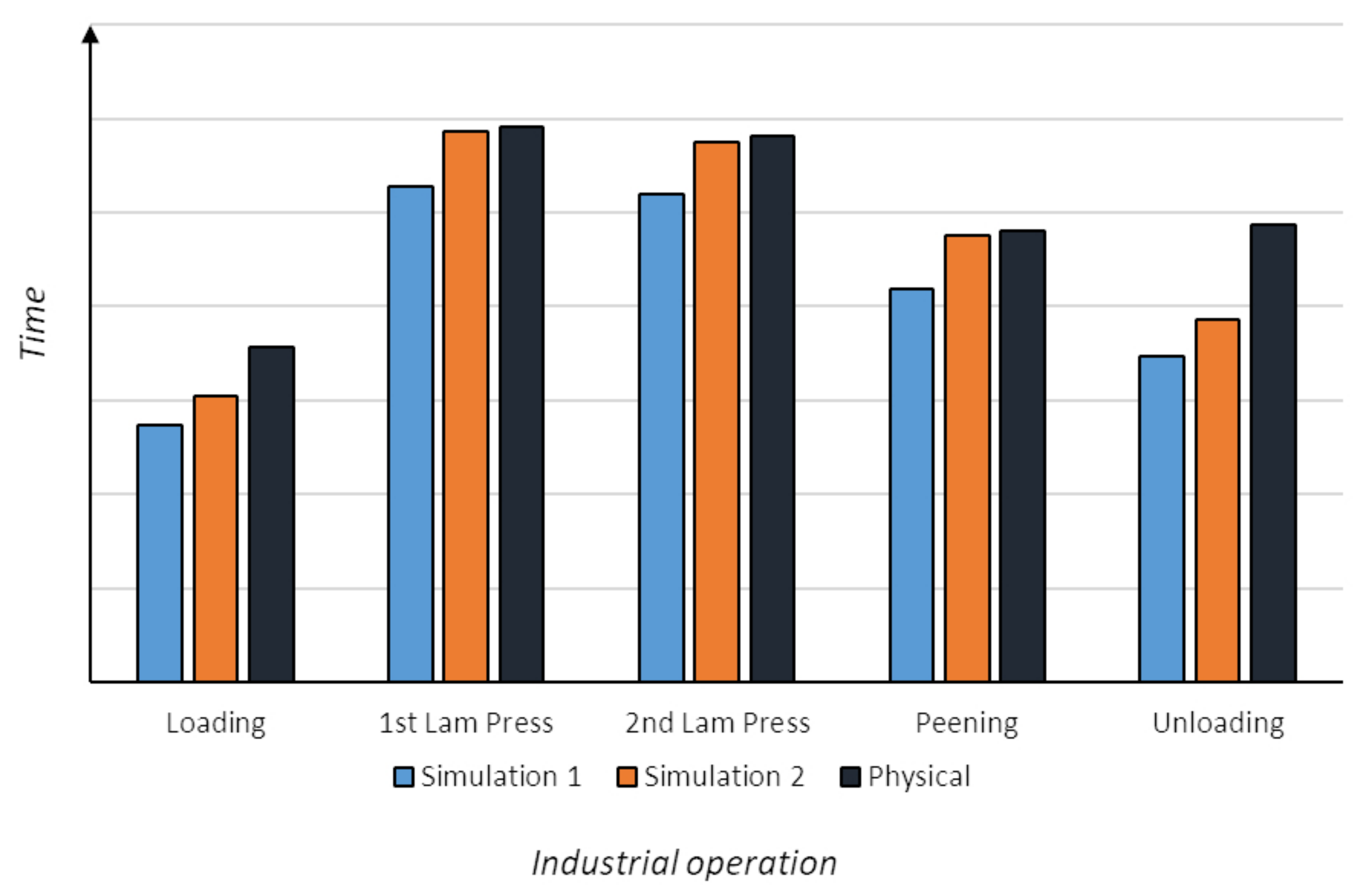
The VE and VC of the vertical assembly station improved its design and functionality during the development phase. By the completion of the design and process development phase and the beginning of the physical build phase, more precise calculations of the machine cycle time were available, and the simulation could be adjusted.
Figure 11 shows the change in exemplary industrial processes’ cycle times during the initial simulation and the final one. These, in turn, can be compared to the actual physical process cycle time. The final simulation timing difference compared to the timing taken when the machine was commissioned and tested was 8.72% (targeted simulation/actual time difference was no more than 5%). This affected the cycle and tact timing information provided for the end user for the motor assembly process.
Table 1 shows the average cycle time difference in percent. The main difference between simulated and physical cycle times was in the manual loading and unloading processes. This is because, due to the new design of the trolleys with new rotor fixtures, the operator had to additionally open a rotor cover. Therefore, the time for loading was increased. Additionally, the lift assist timing assumptions were not accurate, so the actual unloading time was greater than the simulated time.
It can be noticed from
Figure 11 and
Table 1 that the proposed methodology led to building a virtual model capable of supporting the end user requirement. Furthermore, the resultant virtual model constitutes the basis of creating the digital twin.
As mentioned earlier in the methodology (
Section 4.2), the resultant DT is meant to demonstrate a set of features that are detailed in
Table 2 and evaluated as “Achieved”, “Ready” and “Achievable”. After the implementation of the case study, these features are as follows:
Document management: all the documents, drawings, CAD models, components, MODAPTS tables, etc. are stored in the cloud database and can be accessed by the vueOne application during each stage of the DT development. For example, at the validation stage, the MODAPTS documents can be generated to compare the virtual model to the physical and find the cause of the differences. The maintenance documents and recordings can be accessed online by the fault tracker option.
Model: the virtual model of the machine can mimic the physical machine, its behaviour, features, and functionalities.
3D representation: the properties of the physical machine are represented and mapped to the 3D digital representations.
Simulation: the behaviour of the devices of the physical machines is represented in a simulation environment, where the necessary studies were made such as: kinematics behaviour and properties, physics (where necessary, e.g., gravity conveyor), manual, semi-automatic and automatic processes.
Data model: the data model is standardised according to IEC, IEEE, and OPC standards. The connection is executed via OPC UA, TCP IP and PROFINET.
Visualisation: there is a dynamic graphical representation of the physical machine with the connection to a PLC real-time.
Model synchronisation: The model is connected online to the physical machine’s PLC, where it has access to all the parameters, data and input-outputs of the actuators and sensors. The virtual twin of the machine can mimic the physical machine online via the OPC UA interface connected to the machine’s PLC and behave according to the physical machine’s signals.
Connected analytics: the physical machine properties are measured, recorded and analysed by applications, such as the fault tracker application, key performance indicators (KPIs) analytics, etc. This is done for future predictive maintenance, operation planning and control.
The connected analytics feature is still in development. The fault tracker can track, store and represent all the faults and can predict the fault or maintenance needed according to the usage of the component, its historical and real-time data. The data are stored in a SQL database and should be accessible online via the vueOne application.
The digital twins of this and other manufacturing systems allow a considerable potential for the reconfigurability tests in the virtual environment before the reconfiguration of the physical machines. When a new product or process needs to be introduced, its manufacturing can be tested on the existing virtual models of the machines and the whole layout setup. The changes can be done in the virtual machines models and then can be connected to the physical machine’s PLC and emulated in the real working environments. Other process changes can also be tested virtually before applying them in the real world: increases in productivity and capacity, health and safety improvements, quality, etc.
Digital twins can also be further used as digital shadows of the production processes for monitoring and predictive maintenance during the operation phase. It can visually shadow the processes for the better presentation and monitoring of production from remote locations. Additionally, digital twins can have additional software for process monitoring, data analytics, prediction and control, such as the number of cycles of the machine or tooling components’ moving parts, and can predict when the maintenance is needed.
5.8. Limitations
Despite the satisfactory results of VE and VC, the development of the virtual model still takes considerable time, and additional engineering resource have to be allocated for this procedure, in addition to some encountered problems.
During the auto cycle, the VC application allows monitoring and testing the sequence of the station operation. However, some loading/unloading, positioning and other actions are to be triggered manually via the application interface through input/output buttons. The values of the servo drive parameters, such as force, speed, etc. are also to be written by the operator via the application interface text field. These values will update the OPC-UA server and then update the PLC with HMI.
There are some missing functions and updates for the VE and VC tools: the servo drive jog mode was not simulated, emergency shut down does not stop the machine moving parts immediately, only when they arrive at the next state, and pneumatic cylinder and servo drive movement timings were not accurate. There were not several options for the servo, such as acceleration/deceleration, load, state information, etc. Additionally, the MLP facility uses an application with an SQL database connected through the OPC UA server to all the stations. This application collects all the information from the parts/products from the motor assembly process via barcodes on the parts and scanners at each station. The operator scans the part before and after the operation, so that the product, operation, and other parameters are tracked. This process was not simulated or virtually commissioned during the project. The virtual model did not use a barcode scanner and was not connected to this application server.
Another drawback was the PLC software code modification for the duplication of physical inputs with the memory signals. This was done due to the fact that Siemens S300 PLC and PLCSIM do not allow to change the physical inputs from the external communication applications (it checks the input in the internal memory, and if a signal was forced, the processor overwrites the signal with ‘false’ each subsequent cycle). Manual IO mapping and description, along with the linking points shifting description in the .json file of the OPC Gateway application, was also time- and effort-consuming and must be automated in the next application release.
6. Conclusions
In response to the ever-increasing demand for shortening manufacturing system development lifecycles, the current work relied on VE and VC for the facilitation of this challenging task. The current work is dedicated to delivering the end user requirements in terms of production planning in the first place and then having a template of the digital twin to be utilised in the following phases of the system lifecycle. To achieve this, the proposed methodology utilises the vueOne toolset developed by the Automation Systems/Warwick Manufacturing Group at the University of Warwick.
The paper describes how VE and VC can support an industrial project lifecycle. A number of virtual models of manufacturing stations are used for process planning, layout configuration, ergonomics and safety analysis, and PLC code validation before the physical machines are built. The paper focuses on one station (the vertical assembly of rotors) as a case study where the VE and VC support the machine’s development process from the initial design to the physical commissioning and operation phases of the station development. The methodology aims to satisfy end user requirements considering reducing the virtual model development time and effort. The results show that further to the virtual model creation and development, it could give a good representation of the modelled station behaviour. Such a model can assist the end user in delivering the production aims. Furthermore, it allows multiple reconfiguration opportunities and futuristic change implementations.
Although VC was completed successfully, and the improvements can be noticed, there still exist some limitations that need to be addressed and tackled. The planned future research works will take these limitations into account and introduce applicable solutions to them. The future work also aims to establish a full digital twin of this vertical assembly station with the ability to integrate virtual mechatronic components. The intended DT allows precise monitoring of each component and the station overall, with predictive maintenance capabilities as well as the analytics and control of the production processes. Furthermore, the DTs of all MLP stations, parts and products are to be developed towards creating a digital factory.


