Article

Dynamic Response in Multiphase Electric Drives: Control Performance and Influencing Factors

by
Angel Gonzalez-Prieto
,
Ignacio González-Prieto
*,
Mario J. Duran
and
Juan J. Aciego
Department of Electrical Engineering, Engineering School, University of Malaga, 29071 Malaga, Spain
*
Author to whom correspondence should be addressed.
Machines 2022, 10(10), 866; https://doi.org/10.3390/machines10100866
Submission received: 12 August 2022 / Revised: 22 September 2022 / Accepted: 23 September 2022 / Published: 27 September 2022
(This article belongs to the Special Issue Innovative Applications of Multiphase Machines)

Abstract

:
Speed variable electric drives play a key role in the evolution of electrical mobility. The dynamic performance of these systems is a crucial feature for security purposes. For this reason, a large number of works are focused on identification of the most appropriate control technique to satisfy a transient scenario. In this regard, the dynamic abilities of linear and direct controllers were analysed for three-phase drives. Although some insights about their transient performance were obtained, there are yet some issues to be solved. For instance, speed response was typically omitted, some influencing factors were neglected or the multiphase case was carried out. Considering this information, this work proposes a comparative analysis of the dynamic performance of the most popular regulation strategies for a six-phase electric drive. This study analyses speed, current and voltage responses to achieve an overall view of the system performance. Two concepts were employed to simplify the comprehension of the dynamic behavior of a regulation strategy: reaction time and response capacity. Experimental results are employed to confirm the impact of the different agents on a transient situation.

1. Introduction

Climate change and energy transition require reformulating the management of the available ecological resources to ensure the viability of our planet. Two factors need to be analysed in this regard: energy consumption and the emission of polluting gasses. As a consequence of this critical scenario, green-energy generation and electrical mobility based on electric drives have been promoted in the last decade. However, to satisfy their new role in society, they require even more progress in their performance. Multiphase systems appear as an interesting alternative to fulfill the more restrictive requirements of the new generation of electric drives. These special electrical systems offer several substantial advantages in comparison with conventional three-phase electric drives, such as a smaller torque ripple [1], a better fault tolerance [2] and a lower per-phase current rating for the same phase voltage [3]. As a consequence of these suitable features, several research groups are focused on the improvement of the multiphase machine design, using for that purpose modern optimisation techniques [4,5,6]. On the other hand, high-performance control techniques are also required to exploit the benefits of multiphase electric drives [1,2,3,7]. Given the number of industry applications where a variable speed system is regulated, for example, electrical vehicles, a suitable dynamic response can be considered as a principal requirement for a high-performance control scheme.
Considering the current state-of-the-art, classical linear controllers, such as indirect rotor field-oriented control (IRFOC) schemes, have been selected as one of the most preferable control solutions for multiphase electric drives [8]. This family of regulation techniques provides a low harmonic distortion and a robust tracking of the control variables [8]. Reduced harmonic content is typically achieved with the implementation of an explicit modulation stage, whereas the usage of proportional-integral controllers permits solving some disturbance problems. In spite of the popularity of IRFOC strategies, some limitations have also been identified concerning their performance, including a reduced utilisation of the DC-link voltage and a limited flexibility in terms of creating online control actions, when the classical versions of the explicit modulation stages are employed. However, some of these limitations have been solved with the development of new proposals that replace those standard modulation strategies at the expense of a higher computational burden and complexity [9]. The improvement in the DC-link voltage usage is typically addressed with the injection of a specific harmonic content according to the operating point [10,11,12,13]. This solution was developed for conventional pulse-width modulation techniques employed in multiphase systems. Direct control techniques are considered an interesting alternative to linear controllers in multiphase electric drives. In this regard, finite-control-set model predictive control (FCS-MPC) appeared in 2009 [14], providing a proof of concept concerning the advantages of FCS-MPC in the field of multiphase systems. Its conceptual simplicity and flexibility have been highly appreciated by the research community. Nevertheless, a reduced current quality limited the viability of FCS-MPC as a high-performance control technique for a significant period of time. An additional benefit of FCS-MPC usage is its suitable dynamic response; this feature is crucial in industrial applications such as electric vehicles, more-electric aircraft or aerospace systems.
There is a substantial number of works about three-phase electric drives where a comparative analysis concerning the dynamic abilities of IRFOC and FCS-MPC was carried out [15,16,17,18,19,20,21,22]. These studies were conducted from qualitative [19,20] and quantitative perspectives [15,16,17,18,21,22]. Concerning the first type of analysis [19,20], the dynamic performance assessment was approached in terms of current response. In the case of [20], the conclusions are based on simulation results where the current of the main plane was employed as the basis of the proposed comparison. The implemented control schemes in this work were FCS-MPC and IRFOC using a carrier-based pulse-width modulation (CB-PWM) stage. According to the qualitative results, a better FCS-MPC dynamic response is obtained because the conventional CB-PWM cannot achieve a unitary modulation index and thanks to the use of a large predictive horizon in the case of FCS-MPC. Ref. [19] employed numerical simulations and experimental results to analyse from a qualitative point of view the capacity of these regulation techniques to satisfy a transient situation. The work also focused on the current response since an R L load was employed and therefore the transient speed behavior was omitted in [19]. Concerning the quantitative studies [15,17,18,19,20], the use of an explicit modulation stage was identified as a significant limiting factor of the dynamic response of IRFOC [16,17,18,21]. However, the impact of the modulation stage on the dynamic performance and the analysis of causality is addressed from different perspectives. In [17], the reduced utilisation of the DC-link voltage is exposed as the limiting factor, whereas in [18,21] the delay added in the current response due to the implementation of a space-vector pulse-width modulation (SV-PWM) is identified as the cause of this poor performance. In addition, ref. [16] highlighted the low band-width of the modulation stages as the influencing factor in the dynamic behavior of linear controllers. On the other hand, ref. [15] introduced the limited dynamic ability of control schemes based on a cascade structure as a main cause of the transient misperformance. Nevertheless, the speed tracking of electric drives ensures a cascade strategy for IRFOC and FCS-MPC techniques; therefore, this issue cannot be strictly considered as a source of divergence. Regardless of the nature of the analysis, the speed response is typically omitted as a consequence of the use of R L load [17,19,20,21] instead of an electric machine. Therefore, the influence of the control scheme on the mechanical speed response could not be established. In order to solve this issue, ref. [22] proposed a comparative analysis of speed regulation in transient situations using IRFOC and FCS-MPC. However, only simulation results were employed to provide the conclusions.
Considering the increase in the use of multiphase technology for variable-speed electric drives and the limitations of previous studies concerning three-phase systems, this work proposes for the first time a comparative analysis of the dynamic performance of conventional IRFOC without a specific harmonic injection and FCS-MPC in multiphase drives. Its main objective is to provide consistent conclusions concerning speed, current and voltage behavior in transient scenarios. For that purpose, a six-phase electric drive is employed as a case study. Experimental results are employed to validate the analytical approaches provided concerning the reaction time and response capacity of the considered control schemes. In this regard, three different regulation techniques were implemented: IRFOC CB-PWM, IRFOC SV-PWM and FCS-MPC using large voltage vectors as active control actions. The main factors that influence the dynamic performance are explored from analytical and experimental perspectives. For instance, the impact of DC-link voltage utilisation and the integral terms of the linear controllers are analysed. On the other hand, as a consequence of the lower switching frequency of FCS-MPC strategies [14], it is common to implement this control technique using a higher sampling frequency than in IRFOC [23]. This assumption is necessary to achieve a fair comparison in a steady state; however, it can also omit some significant information about the transient response of the studied regulation techniques. For this reason and in contrast to previous studies, this work considers this implementation variable as an influencing factor in the dynamic behavior of these popular control schemes. It is worth highlighting that the conclusions from this analysis are valid for electric drives using multiphase induction machines and conventional Si-based voltage source converters (VSCs) at standard switching frequencies (between 1 and 10 kHz). The advent of wideband-gap devices (e.g., SiC and GaN switches) could promote a review of the obtained conclusions, but this technology is still in an initial stage of development in the field multiphase electric drives.
The rest of the manuscript is structured as follows. Section 2 describes the selected topology for the proposed case study. In Section 3, IRFOC and FCS-MPC are presented, as well as the considered explicit modulation techniques. Section 4 provides a detailed insight concerning the variable related to reaction time and response capacity of the different control schemes. Finally, Section 5 and Section 6 present the experimental results and the main conclusions of this work, respectively.

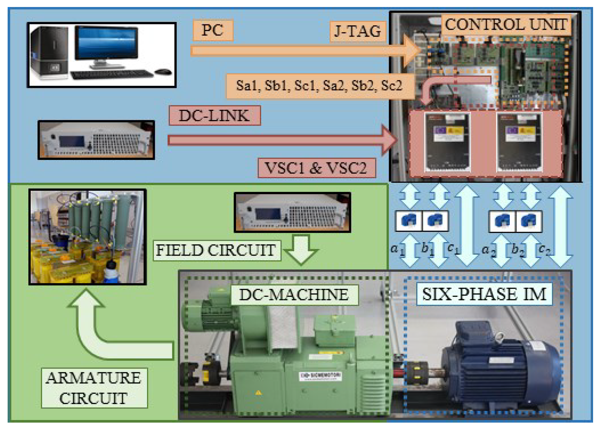
2. Six-Phase Electric Drive Topology

The selected electric drive is formed by an asymmetrical six-phase induction machine (IM) fed by a dual two-level three-phase VSC, as shown in Figure 1. Focusing on the multiphase machine, the stator windings are distributed and spatially shifted 30. In addition, the machine is configured with two isolated neutral points to simplify the control stage [24]. Each stator winding is connected to a two-level three-phase VSC. As depicted in Figure 1, a single DC link is employed in the proposed topology. The stator phase voltages ( v s i ) can be obtained using the DC-link voltage ( V d c ) and the available switching states ( S i j ):
v a 1 v b 1 v c 1 v a 2 v b 2 v c 2 = V d c 3 2 1 1 0 0 0 1 2 1 0 0 0 1 1 2 0 0 0 0 0 0 2 1 1 0 0 0 1 2 1 0 0 0 1 1 2 S a 1 S b 1 S c 1 S a 2 S b 2 S c 2 ,
where S i j is a binary number related to the behavior of each leg of the VSC. If the upper switch of the phase is ON, S i j   =   1 and, in contrast, if the lower switch is ON, S i j   =   0 . Therefore, 64 stator voltage vectors can be obtained in the selected electric drive.
Although phase variables can be used to describe the behavior of multiphase electric drives, the utilisation of different reference frames and transformations facilitates their understanding and control. Among all the available reference frames in the literature, vector-space decomposition (VSD) is one of the most employed approaches [25]. For the proposed case study, this transformation allows expressing phase variables into three orthogonal subspaces using the amplitude-invariant Clarke matrix:
C = 1 3 1 1 2 1 2 3 2 3 2 0 0 3 2 3 2 1 2 1 2 1 1 1 2 1 2 3 2 3 2 0 0 3 2 3 2 1 2 1 2 1 1 1 1 0 0 0 0 0 0 1 1 1 ,
[ v α ,   v β ,   v x ,   v y ,   v z 1 ,   v z 2 ] T = [ C ] [ v a 1 ,   v b 1 ,   v c 1 ,   v a 2 ,   v b 2 ,   v c 2 ] T ,
[ i α ,   i β ,   i x ,   i y ,   i z 1 ,   i z 2 ] T = [ C ] [ i a 1 ,   i b 1 ,   i c 1 ,   i a 2 ,   i b 2 ,   i c 2 ] T ,
where α - β components are related to torque/flux production, x-y components only produce stator copper losses in machines with distributed stator windings and z 1 - z 2 currents present a null value due to the use of two isolated neutral points.
The stator voltage vectors can be mapped onto α - β and x-y planes. For that purpose, Equation (2) needs to be applied. In Figure 2, each voltage vector is identified using a decimal number equivalent to the binary number of the vector S   =   [ S a 1 ,   S b 1 ,   S c 1 ,   S a 2 ,   S b 2 ,   S c 2 ] . According to their magnitude in the α - β plane, the voltage vectors can be sorted in five groups: large ( C l ), medium-large ( C m l ), medium ( C m ), small ( C s ) and null ( C n ) [26]. Their production in the main plane is directly related to their dynamic performance, as shown in the next sections.

3. Analysed Control Schemes

3.1. Indirect Rotor Field-Oriented Control

The indirect field-oriented control operating principle is based on decoupling flux/torque production to regulate the machine in a similar manner to a DC machine [8]. For that purpose, the aforementioned α - β components are projected onto a rotating reference frame (d-q system). The d-component is generally aligned with the rotor flux, decoupling the flux generation from the electrical torque production. The Park matrix permits the transformation to this rotating reference frame and is typically expressed as:
D   =   cos ( θ ) sin ( θ ) sin ( θ ) cos ( θ ) ,
[ i d ,   i q ] T = [ D ] [ i α , i β ] T ,
[ i x 1 , i y 1 ] T = [ D ] 1 [ i x ,   i y ] T ,
where θ is the angle of the rotating reference frame that is calculated from the measured speed and estimated slip [27]. For the proposed electric drive, the α - β components are rotated using Equation (4), whereas the secondary subspace is usually rotated using an anti-synchronous rotating reference frame to compensate for possible asymmetries in the machine [24].
Applying the aforementioned transformation, d-q and x 1 - y 1 currents can be regulated in an effective manner using proportional-integral (PI) controllers. As shown in Figure 3, the standard IRFOC scheme presents two different control loops. On the one hand, there is an outer speed-control loop, where the difference between the measured and reference speed is employed as an input of the outer PI controller. On the other hand, in the inner-control loop, several current controllers are employed to ensure the flux/torque regulation and to provide an acceptable harmonic distortion. The reference value of the d-current is set to its nominal value in order to ensure a correct magnetisation level. Focusing on the speed response, it is directly related to the q-current as a consequence of the relationship between this component and the electrical torque production. Finally, the reference value of the x 1 - y 1 currents is set to zero to minimise the stator copper losses since a distributed stator is employed in the proposed multiphase IM.
The output of this cascade-controller scheme is the reference value of the d-q and x 1 - y 1 voltages. Then, an explicit modulation stage is required to determine the switching states and their corresponding duty cycles to achieve the reference phase voltages. Among all the available explicit modulation techniques developed in the state-of-the-art, CB-PWM and SV-PWM stages have been the most employed choices [28].
Based on the mandatory use of an explicit modulation stage, the performance of IRFOC needs to be analysed in conjunction with the implemented modulator. For this reason, the next subsections describe the foundations of the aforementioned modulation techniques.

3.1.1. Carrier-Based Pulse Width Modulation

In the field of electric drives, the CB-PWM strategy is considered the most popular modulation technique [29] due to its easy implementation in digital-signal processors (DSPs) and its reduced harmonic content in conventional three-phase systems. The operating principle of this modulation scheme can be described in brief. The control actions (switching states and duty cycles at each sampling period) are obtained through a comparison of the reference phase voltages and a predefined carrier signal. Moreover, a single phase description can be employed to describe its behavior (see Figure 4) without lack of generality since the method is based on phase variables. As shown in Figure 4, in each control period the performance of the VSC leg a will be defined by the comparison between the reference phase voltage and the carrier signal. For instance, when the latter presents a higher value than the reference variable, the gating signal a is set to zero. On the other hand, when the carrier signal has a lower value than the reference voltage, the gating signal S a becomes equal to one. Based on the nature of this modulation technique, the control designer posses a reduced capability to know in advance the applied switching states and their corresponding duty cycles because the control actions are obtained in the aforementioned comparison.
Focusing on the carrier signals, different features, such as frequency and amplitude, need to be satisfactorily configured in order to obtain a suitable performance. The triangular-carrier signal has been considered as the preferable solution due to its suitable performance from the point of view of harmonic mitigation. However, several alternatives have been employed in the literature, such as sawtooth-carrier and inverted sawtooth-carrier signals [30]. In this work, according to its more competitive features and higher use, triangular-carrier signal was selected as the CB-PWM benchmark.

3.1.2. Space-Vector Pulse Width Modulation

SV-PWM techniques are a popular alternative to CB-PWM, due to their higher flexibility in the design of the control actions and their better utilisation of DC-link voltage. The goal of this modulation strategy is the same as in the case of CB-PWM, i.e., to determine the signal gates and their corresponding duty cycles to feed the machine with voltages that are as close as possible to their reference values. In the case of SV-PWM, the inputs of the modulation strategy are the reference values of the VSD voltages ( V α β * and V x y * ). The operating principle of this modulation technique is formed by offline/online stages. Firstly, the α β plane is split into different sectors according to the employed topology and the control purposes. This task is carried out offline by the control designer, who also needs to define the voltage vectors associated with each sector according to the control requirements. Focusing on the real-time control, the location of V α β * and V x y * is used to determine the voltage sector for each control period. This fact allows determining the applied switching states for the required voltage output. Finally, the corresponding duty cycles are obtained solving an analytical expression that ensures that the average α - β and x-y voltages are equal to their reference values. For that purpose, the contribution of the selected voltage vectors in the different subspaces and the reference voltages are employed (see Equation (6)).
Regarding the design of the control actions, the number of voltage vectors employed to provide the voltage requirements depends on the electric drive parameters and the control objectives. In the case of a six-phase IM with two isolated neutral points, four different voltage references are provided by the control scheme, [ V α * , V β * , V x * , V y * ]. For that reason, a total of five voltage vectors are typically required to fulfill all reference values. Their duty cycle can be obtained by solving the following system of equations [31]:
t V 1 t V 2 t V 3 t V 4 t V n u l l   =   V 1 α V 2 α V 3 α V 4 α V n u l l α V 1 β V 2 β V 3 β V 4 β V n u l l β V 1 x V 2 x V 3 x V 4 x V n u l l x V 1 y V 2 y V 3 y V 4 y V n u l l y 1 V α * · T s V β * · T s V x * · T s V y * · T s T s .
At this point, the control designer can take advantage of the SV-PWM flexibility to decide the voltage vectors associated with each voltage sector. For example, in the control scheme defined as a case study, the main objective is to maximise the flux/torque production, whereas the stator copper losses are minimised. Taking into account those requirements, large voltage vectors in α - β can be selected as the recommended active control action since they provide maximum torque/flux production combined with a minimum contribution in the secondary plane [26]. For this reason, four adjacent large voltage vectors are associated with each voltage sector. Figure 5 shows the different sectors defined for the electric drive selected as a case study.
On the other hand since several voltage vectors must be applied during a sampling period, there are multiple options for the arrangement of these vectors. A suitable disposal can minimise the impact of the non-linearity of the VSC and thus reduce the active production in the secondary plane. Under certain machine parameter conditions, the use of discontinuous switching patterns can improve the harmonic content and reduce the switching frequency [31]. Considering this information, a discontinuous switching pattern was implemented in this work when an SV-PWM technique was implemented.

3.2. Model Predictive Control

Finite-control-set model predictive control strategies can be considered as a serious competitor to IRFOC schemes thanks to their inherent advantages over conventional linear controllers. These two families of control techniques present significant differences in their structures. In the case of FCS-MPC, the use of an explicit modulation technique is not required since the control actions are directly evaluated in the control scheme. For this reason, FCS-MPC is classified as a direct-control strategy. Nevertheless, they also show some important similarities; for example, both incorporate a cascaded structure. The standard FCS-MPC version (shown in Figure 6) is formed by an outer PI controller to carry out speed tracking and an inner-control loop based on a predictive model to ensure current regulation. Following a cascaded control structure, the PI controller provides the q-current reference, whereas the d-current reference is fixed to its rated value to reach the nominal stator flux. Regarding the inner-control loop, the currents are regulated in a synchronous reference frame using a predictive model of the machine. This approach permits avoiding the regulation of sinusoidal signals since they can degrade the transient response of the electric drive [21]. To overcome this limitation, a predictive model referring to a synchronous reference frame was employed in this work [21]. Using the Forward Euler discretisation technique, the machine model can be described as [32]:
d d t [ X d q x 1 y 1 ]   =   [ A ]   ·   [ X d q x 1 y 1 ]   +   [ B ]   ·   [ U d q x 1 y 1 ] ,
where
[ X d q x 1 y 1 ]   =   [ i d s , i q s , i x 1 , i y 1 , λ d r , λ q r ] T , [ U d q x 1 y 1 ]   =   [ u d , u q , u x 1 , u y 1 , 0 , 0 ] T ,
matrices [ A ] and [ B ] are defined by the dynamic behavior of the six-phase induction machine and their coefficients are parameter-dependent [32].
The standard FCS-MPC is based on a two-step prediction horizon ( k + 2 ) and, therefore, the one-step delay compensation approach is intrinsically included [32]. In the first stage, the predicted currents i ^ d q x 1 y 1 | k + 1 are obtained as a function of the mechanical speed ω m | k , the measured stator currents i d q x 1 y 1 s and the applied switching state in the previous sampling period. Then, in the second stage, the predicted currents i ^ d q x 1 y 1 s | k + 2 produced by each available control action are obtained and evaluated in a cost function to select the optimum switching state. This cost function can be defined as:
J   =   e d s 2   +   e q s 2   +   K x y   ·   ( e x s 2   +   e y s 2 ) ,
with
e d s   =   i d s * | k + 2     i ^ d s | k + 2 ,
e q s   =   i q s * | k + 2     i ^ q s | k + 2 ,
e x s   =   i x 1 * | k + 2     i ^ x 1 | k + 2 ,
e y s   =   i y 1 * | k + 2     i ^ y 1 | k + 2 ,
where K x y is a weighting factor related to the x 1 - y 1 current control. The value of this parameter is tuned up to obtain a suitable flux/torque regulation and mitigated x-y current production.
FCS-MPC presents much flexibility concerning design of the control actions; in other words, the control designer can promote the voltage vectors with a high performance according to the control objectives. As in the SV-PWM case, a suitable selection of the switching states permits improving the overall performance of the electric drive. In this regard, large voltage vectors present maximum production in the main subspace and minimum contribution in the x-y plane. Moreover, the use of reduce set of voltage vectors also decreases the computational burden of the FCS-MPC, one of the main disadvantages of this regulation technique [21]. For the sake of simplicity, this control scheme is referred to as LFCS-MPC throughout this work and its dynamic performance will be analysed in the next sections.

4. Dynamic Performance: Factors Influencing the Transient Response

This section aims to provide an insight concerning the factors that influence the transient response of the considered control schemes. The dynamic performance can be analysed from two differentiated points of view: on the one hand, the reaction time of the regulation strategy when a change in the reference variables appears and, on the other hand, the response capacity provided by the regulation technique to adapt the control variables to the new transient situation. All the different items presented in this section will be verified in the experimental results included in the following section.

4.1. Reaction Time of the Control Scheme

The reaction time of a regulation technique can be defined as the time employed by the algorithm to notice a change in the reference signal. This dynamic feature can be measured by the dead-time and the slope of reference control variables during the transient situation. Among the agents related to this index, the sampling period and the structure of the regulation strategy can be highlighted.

4.1.1. Sampling Period

From a theoretical perspective, the sampling period is the minimum detection time that a regulation technique needs to identify a change in the reference signal. Based on this fact, if a regulation algorithm has a higher control frequency, a lower reaction time is expected.
It is habitual in the field of electric drives to employ an equivalent average-switching frequency when the steady state performance of several control techniques is analysed. This approach can involve the utilisation of different sampling periods for diverse regulation strategies. For instance, in the case of FCS-MPC, the switching frequency is variable and, in addition, lower than the sampling frequency [14], whereas in IRFOC schemes sampling and switching frequency can match. Based on these operating conditions, FCS-MPC is generally implemented with a higher sampling frequency than in the case of IRFOC in order to determine the harmonic distortion at the same switching frequency. However, if the dynamic response is studied using an equivalent average-switching frequency, FCS-MPC will have a lower control period and, consequently, could achieve a better reaction time. In spite of the disturbances caused by the use of a different control period from the perspective of a fair dynamic comparison, this implementation solution was applied in different comparative works [15,16,17,18,19,20,21,22] and hence the impact of the sampling period on the dynamic performance was omitted.
In order to quantify the effect of the sampling period on the transient response of a control scheme, two different experimental tests will be carried out in this work. Firstly the dynamic performance of IRFOC CB-PWM, IRFOC SV-PWM and FCS-MPC is analysed when the three regulation techniques provide an equal average-switching frequency. Finally, a second test will be conducted to study the transient behavior when they are employing the same sampling period.

4.1.2. Control Structure

The control structure was also identified in [33] as a factor influencing transient behavior. According to the considered control schemes, they show a cascade topology, where the outer-control loop is related to the speed regulation and the inner-control loops ensure current tracking. This topology is the most employed control solution for electric drives because its implementation permits a suitable mitigation of the signal disturbances. However, a certain delay in the reaction time of the outer-control variable can appear as a consequence of the nature of this structure. In other words, the outer-control loop requires a fast response of the inner-control loop to react to the new value of the reference signal [33].
To avoid this limitation in the reaction time, the control variables of the inner-control loops need to be characterised by a significantly lower timing constant than in the case of the outer-control variable [33]. The mechanical and electrical timing constants of electric drives fulfill this requirement and therefore a suitable dynamic response can be achieved with the implementation of a cascade topology [33].
Considering the control schemes of this work, all of them are based on a cascaded structure and hence this factor cannot be identified as a determining variable of their dynamic performance.

4.2. Response Capacity

The response capacity can be defined as the ability of a control technique to satisfy the tracking of the reference variables in a fast form. This control characteristic is usually quantified in terms of settling and rise times [21]. As in the reaction time case, several factors play a fundamental role in the response capacity and, therefore, in the dynamic performance of a control scheme. In this regard, the impact of two agents needs to be highlighted, the usage of the DC-link voltage and the implementation of integral terms in the control loops.

4.2.1. Utilisation of the DC-Link Voltage

DC-link voltage usage was considered a determining factor in the dynamic performance of a control scheme in several works [20]. A high voltage production allows the regulation technique to achieve a better response capacity to satisfy the transient scenario. In this regard, the flexibility to create control actions is crucial to take advantage of the DC-link voltage.
Focusing on DC-link utilisation, ref. [28,32] estimated the maximum voltage production for linear and direct controllers in a multiphase system. Some interesting conclusions can be obtained from these works, the CB-PWM technique working in a linear region has a DC-link voltage usage of 1 / 2 · V d c [28]. On the other hand, the SV-PWM stage presents a utilisation of the available DC-link voltage of 1 / 3 · V d c [28] when the linear region is tested. Finally, in the FCS-MPC case, the DC-link harnessing increases up to 0.644 · V d c [32], achieving better DC-link usage. Therefore, it is expected that the FCS-MPC will provide the better current response, followed by the SV-PWM and, finally, the CB-PWM case. This performance can be observed, for example, in the slope of the measured q-current when the transient scenario appears. In addition, a higher operating range can be obtained as a consequence of the improvement in the DC-link achievement. In this regard, harmonic injection is a suitable technique to enhance the voltage usage in a six-phase electric drive when a CB-PWM strategy is implemented [34]. However, this work is focused on a comparative analysis when the basic version of the considered control schemes is used.
To confirm these assumptions, the following section provides experimental results where two different DC-link voltage conditions were explored.

4.2.2. Integral-Term in Control Loop

Finally, this point describes the effect of the integral term of PI controllers on the response capacity of a control scheme. To understand the impact of this factor on the dynamic response, it is necessary to recall the operating principle of these controllers. Their working principle can be divided into two stages that run in parallel: the proportional and the integral control stages. In the proportional module, the variation of the output signal is based on the present error between the measured and reference signals; hence, focus is established on the dynamic response (i.e., the instantaneous reaction to correct the error). However, this stage cannot mitigate steady-state errors because the past is neglected. This fact makes obligatory the use of an integral stage. In the integral stage, the output variable is adjusted to minimise the accumulated error between the measured and the reference signal, decreasing the steady-state error. Therefore the output of the controller is dependent on two control objectives, the cancellation of transient and steady-state errors. In other words, the controller response is a trade-off between a suitable dynamic response and the minimisation of steady-state errors [33].
Concerning the tested control schemes, IRFOC is characterised by the use of PI controllers in both control loops and thus the influence of the integral term can be higher than in the case of FCS-MPC. For this reason, the effect of this factor in the dynamic response was assessed for the case of this linear controller.

4.2.3. Additional Factors: Mechanical Inertia and Delay in the Measurement Tasks

In addition to the previous agents, there are two other factors to take into account in the dynamic response of electric drives: the inertia of the electric machine and the measurement-time delay. Analysing the first factor, the inertia of the machine acts as a low-pass filter between the mechanical speed and the electrical torque (related to the q-current). In terms of dynamic response, the use of a filter stage provokes a delay between the original and filtered signal [35]. For that reason, under a transient scenario, the currents will increase their value instantaneously to adapt to the new situation but the speed will take a certain amount of time to react to the current variation. In fact, in some electric drives a better current regulation in transient scenarios cannot ensure a significant improvement in the speed response.
Regarding the measurement-time delay, the role of the optical encoder needs to be highlighted because the sampling period of this sensor is typically higher than the control period. This sensor feature can generate a certain delay in the reaction time of the control scheme [36].
From the point of view of the proposed comparison, the control schemes were tested using the same machine and optical encoder. For this reason, these agents do not have an impact on the comparison.

5. Experimental Results

5.1. Experimental Test Bench

The experimental tests were carried out in the test bench of Figure 7. As exposed in Section 2, the electric drive is formed by an asymmetrical six-phase induction machine with two sets of three-phase windings spatially shifted 30. A dual three-phase two-level VSC (Semikron SKS22F) feeds the stator windings, whereas a single DC link supplies the VSCs. The machine parameters were obtained using AC time domain and still with an inverter supply test [37,38]. These parameters are summarised in Table 1.
The selected control schemes are implemented in a digital-signal processor from Texas Instruments, TI, (TMS320F28335) using a J-TAG connector and the TI property software (Code Composer Studio). Four hall sensors (LEM LAH 25-NP) and an optical encoder (GHN510296R) measure the current and mechanical speed values. Finally, the IM is loaded coupling its shaft to a DC machine used as a generator. The armature circuit of this machine is connected to a variable passive load that dissipates the power. For this reason, the load torque in the electric drive is speed-dependent.

5.2. Experimental Proposal

The purpose of this section is to validate with experimental results the influence of aforementioned factors on the dynamic performance of the considered regulation algorithms. With this objective in mind, a total of four experimental tests were meticulously designed. Speed, current and voltage responses were analysed in order to know the capabilities of these popular regulation strategies when a transient situation appears.
In Test 1, IRFOC and FCS-MPC abilities were assessed when a reference speed step is applied. This first test aims to analyse in a first approximation the dynamic performance of these control schemes, solving some questions about their response time and response capacity. The second test studies the impact of integral controllers under transient scenarios. For that purpose, diverse configurations of IRFOC were implemented and tested. On the other hand, as previously shown, the utilisation of DC-link voltage can be an important agent in the response capacity of a control scheme. Taking into account this issue, two different scenarios were explored in Test 3, where some variations in the DC-link voltage were added. Focusing on implementation details, in this first set of tests, the sampling periods of the regulation techniques were established to provide a similar average-switching frequency. Table 2 summarises the sampling frequency and the average-switching frequency. Test 4 was designed to confirm the influence of control period on the dynamic performance. For that purpose, IRFOC CB-PWM, IRFOC SV-PWM and LFSC-MPC were assessed using the same sampling time in this last test.
Focusing on implementation details, in the case of the analysed IRFOC schemes, several PI controllers need to be tuned in order to provide a suitable response. In this regard, the values of these parameters were obtained using a trial-and-error procedure, this being a common approach in the field of multiphase electric drives [39]. Table 3 and Table 4 show the value of the controller gains. In addition, Table 5 provides the computational burden of the considered regulation techniques.

5.2.1. Test 1: Dynamic Response

This test provides an overall view of the dynamic performances of the considered regulation techniques. Analysing the test conditions, the reference speed changes from 100 rpm to 800 rpm in a step-wise manner. As shown in Figure 8, when the speed step occurs, the q-reference current adapts to the new situation in all cases (Figure 8b). Nevertheless, if the slope of this control variable is observed during the transient scenario, some differences can be identified. Focusing on this response index, LFCS-MPC achieves a better performance since a higher value of the slope appears when this strategy is implemented. However, to associate this improvement to the nature of FCS-MPC, it is necessary to evaluate these control techniques using the same sampling period (see Test 4).
The analysis of the measured q-current permits obtaining some information about the response capacity and reaction time of the implemented regulation techniques. In this regard, control schemes with explicit modulation stages show a slower current response than in the case of LFCS-MPC. Concretely, the rise time increases 59.5 % when a CB-PWM is employed and 48.53 % if a SV-PWM is the selected choice (see Table 6). The reason for this better response is related to the obtained phase voltage waveform for each control solution (Figure 8c). The control techniques with higher time response indices provides lower phase voltages, whereas LFCS-MPC reaches a maximum value of the voltage contribution. As a consequence of the voltage usage, different slopes of the measured q-currents are obtained (see Table 6). This dynamic index allows quantifying in a simple manner the control impact on the dynamics of the drive. On the other hand, considering the reaction time, in the case of LFCS-MPC a lower time is necessary to observe a variation in the measured q-current when the transient situation is provoked. This improvement on the dynamic response was quantified using the dead time of the measured q-current added in Table 6. This dynamic metric is defined by the time lapse between the variation of the reference variable and the initial response of the measured variable and for the considered control schemes LFCS-MPC provides the better result. This improvement can be assumed as a consequence of using a lower sampling period or the absence of an integral controller in the current stage of the FCS-MPC structure. The following tests provide some further insights to clarify these important issues concerning the dynamic behavior of the studied control schemes.
Reviewing the mechanical speed in the considered period, this control variable does not show any variation regardless of the implemented regulation scheme. The inertia of the machine acts as a mechanical filter and consequently the differences in current response do not imply a substantial change in speed performance. In addition, the optical encoder sensor includes a certain delay in the measurement of the speed [36].
In conclusion, although the LFCS-MPC has a faster current response and a better DC-link voltage utilisation, there are diverse factors, such as the inertia of the machine or the existing delay in the measure of the encoder, which make this enhancement negligible from the point of view of the mechanical speed.

5.2.2. Test 2: Integral-Term Influence on the Dynamic Response

This test explores the impact of the integral term of controllers on the dynamic performance of IRFOC. For that purpose, it is necessary to isolate the impact of the integral term on the transient response. For this reason, the proportional term of the q-current is maintained as in Test 1, whereas the integral term is cancelled (see Table 3 and Table 4). The same mechanical conditions of Test 1 are again employed. Figure 9 summarises the experimental results provided by IRFOC-based CB-PWM, whereas Figure 10 shows the results when an SV-PWM is implemented.
Focusing on the case of IRFOC using a carrier-based modulation, the absence of an integral stage allows a lower rise time, decreasing this response index by 21.93 % . Nevertheless, as a consequence of this controller configuration, a steady-state error in the tracking of the q-current appears. Despite the faster response, the steady state performance degradation prevents this choice from being considered an acceptable solution (Figure 9).
Using SV-PWM as the selected modulation technique, the same trend as in the case of CB-PWM is observed, see Figure 10. Omitting the integral stage of the PI controller, the rise time of the q-current decreases by 16.54 % , but a significant steady-state error appears, Figure 10b.
In conclusion, the integral term of the linear controllers shows an important impact on the dynamic response but its absence also shows a negative effect on the steady-state error. For that reason, a trade-off between a suitable steady-state tracking and a proper dynamic performance is necessary when adjusting the control gains in a PI controller. It is noticeable that, regardless of the selected strategy, the mechanical speed of the electric drive has not been immediately affected by the change in the electric variables.

5.2.3. Test 3: Use of the DC-Link Voltage

This test studies the impact of DC-link voltage utilisation on the dynamic response of electric drives. The standard versions of the considered modulation strategies provide a different DC-link usage [28,32] and consequently dissimilar response capacities can be obtained. For that purpose, two different values of the DC-link voltage were employed in Test 3. Table 7 and Table 8 summarise the usage of the DC-link voltage for each control technique in Tests 3A and 3B, respectively.
In the first scenario a value of 300 V was set in the DC-link. According to the dynamic conditions, the reference speed changes from 100 rpm to 775 rpm at t   =   1 s. As shown in Figure 11a, the three control schemes show a suitable tracking of the reference speed. Studying the current response, as soon as the speed step appears, the reference q-current reaches its rated value to satisfy the new operating conditions (Figure 11b). In the case of the measured q-current, the three control schemes achieve an acceptable response because the DC-link voltage allows satisfying the currents requirements.
In the second stage of Test 3, speed and torque conditions are replicated from the first test, but the available DC-link is decreased by 11 % . As can be seen in Figure 12, IRFOC employing an SV-PWM technique and LFCS-MPC are capable of providing a good tracking of the reference speed. Nevertheless, in the case of IRFOC using CB-PWM, the speed tracking cannot be carried out due to the insufficient usage of the available DC link. A lower voltage utilisation supposes a decrease in the current injection and, therefore, a lower electrical torque production. This issue affects the transient performance of the electric drive in speed and current terms. Therefore, this factor needs to be taken into account when a suitable dynamic response is required.

5.2.4. Test 4: Sampling Period on Dynamic Response

Test 4’s aim is to know the impact of sampling time on the dynamic behavior of the considered control techniques. Can the performance conclusions of Test 1 change with the variation of this implementation parameter? In order to solve this question, the same speed and torque conditions of Test 1 are replicated, but in this case the three control schemes are implemented using a control period of 100 μ s. As depicted in Figure 13, the reference q-currents show in this test a similar performance providing an equal slope when the transient situation is provoked. Therefore, in this regard, a new result is obtained when the three control schemes use the same sampling period. Focusing on measured q-currents, LFCS-MPC achieves a better dynamic response than IRFOC alternatives using different modulation stages (Figure 13b). Although the response time is now similar, the higher response capacity of FCS-MPC permits reaching the reference value in a lower time. It is important to highlight that the slope of the measured q-current is not modified as a consequence of the new sampling times (see Table 6 and Table 9). Therefore, the source of this suitable current response is related to the DC-link voltage usage of each control scheme. As shown in Figure 13c, LFCS-MPC provides a higher voltage value when the dynamic situation occurs. Therefore, for a lower switching frequency FCS-MPC can achieve an enhanced-current response. However, as in Test 1, the current dynamic performance has no a significant effect on the mechanical speed of the electric machine (Figure 13a).

6. Conclusions

This work clarifies some issues related to the dynamic behavior of some of the most popular control techniques implemented in multiphase electric drives. In order to provide a generalised response, conventional Si-based VSCs at standard switching frequencies were employed in the selected six-phase drive.
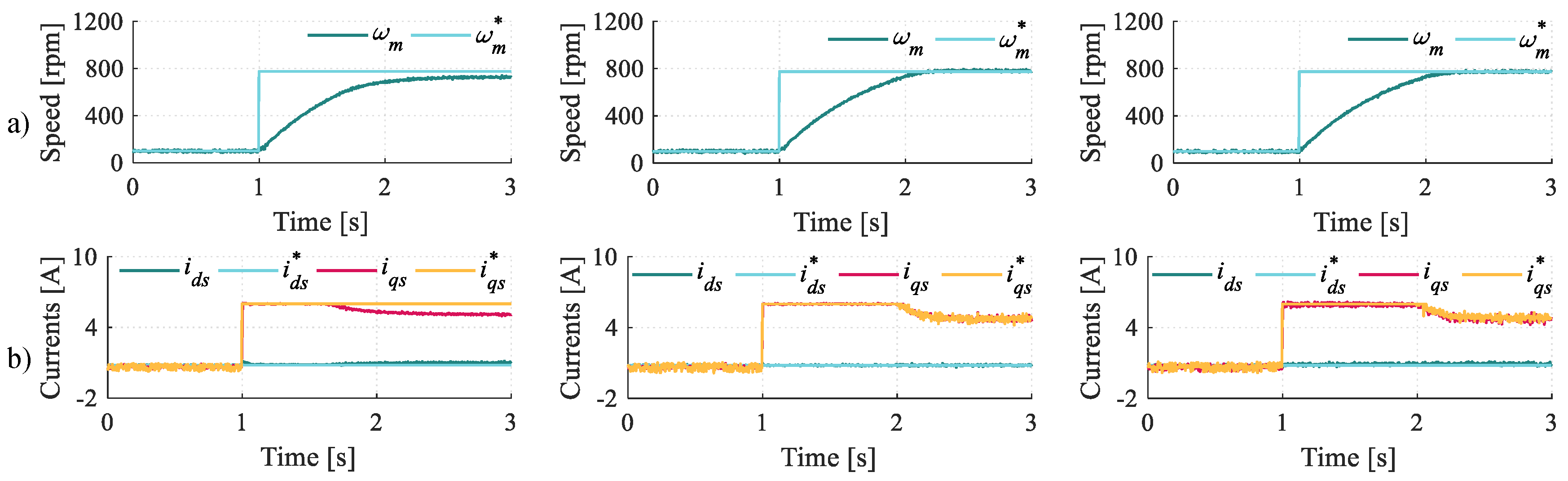
Focusing on speed control, a better current regulation cannot ensure a significantly better speed response due to the mechanical inertia and/or the delay caused by the optical encoder. Analysing the current performance, the results of Tests 1 and 4 provide an interesting conclusion—the sampling period can be considered an influencing factor in terms of reaction time. In other words, IRFOC and FCS-MPC schemes provide the same dead time and slope of the reference q-current when the same sampling period is employed. However, its role in the drive dynamics is shadowed by a factor that proves to be dominating in this case. This significant agent is the usage of DC-link voltage and, in this regard, LFCS-MPC again permits obtaining a better response capacity. In addition, this improvement is achieved with a lower switching frequency for the same control period. However, although FCS-MPC provides better current tracking, the improvement from the point of view of the speed cannot be considered significant due to additional agents. On the other hand, it is necessary to highlight that the reduced utilisation of the DC-link voltage of conventional CB-PWM without harmonic injection can involve a limited mechanical response, as shown in Test 3. In conclusion, IRFOC techniques require the implementation of more complex modulation techniques to provide a higher DC-link usage and then only the integral term will be the single agent that disturbs their dynamic performance from the perspective of the current. Therefore without the utilisation of over-modulation techniques, FCS-MPC will be considered the best option for a transient situation in current terms. Although the advent of wideband-gap devices and more powerful DSPs can provide some advantages in terms of obtaining high-performance control techniques, the role of the voltage DC-link usage can be considered, at this moment, as the crucial factor in obtaining a better dynamic response.

Author Contributions

Conceptualisation, A.G.-P., I.G.-P. and M.J.D.; methodology, A.G.-P. and I.G.-P.; software, A.G.-P. and J.J.A.; validation, A.G.-P., I.G.-P. and M.J.D.; formal analysis, I.G.-P. and M.J.D.; investigation, A.G.-P. and J.J.A.; resources, I.G.-P.; data curation, A.G.-P.; writing—original draft preparation, A.G.-P. and I.G.-P.; writing—review and editing, M.J.D.; visualisation, A.G.-P. and I.G.-P.; supervision, I.G.-P. and M.J.D.; project administration, I.G.-P. and M.J.D.; funding acquisition, I.G.-P. and M.J.D. All authors have read and agreed to the published version of the manuscript.

Funding

This research was funded in part by the Spanish Government under the Plan Estatal with the reference PID2021-127131OB-I00, in part by the Junta de Andalucia under the grant UMA20-FEDERJA-039 and in part by the Ministry of Science, Innovation and Universities under the Juan de la Cierva grant IJC2020-042700-I.

Informed Consent Statement

Not applicable.

Data Availability Statement

Not applicable.

Acknowledgments

The authors of this work appreciate the help provide by the Machine 2021 Young Investigator Awards.

Conflicts of Interest

The authors declare no conflict of interest.

References

  1. Barrero, F.; Duran, M.J. Recent Advances in the Design, Modeling and Control of Multiphase Machines-Part I. IEEE Trans. Ind. Electron. 2016, 63, 449–458. [Google Scholar] [CrossRef]
  2. Duran, M.J.; Barrero, F. Recent Advances in the Design, Modeling and Control of Multiphase Machines-Part II. IEEE Trans. Ind. Electron. 2016, 63, 459–468. [Google Scholar] [CrossRef]
  3. Levi, E.; Bojoi, R.; Profumo, F.; Toliyat, H.A. Multiphase induction motor drives- a technology status review. IET Electr. Power Appl. 2007, 1, 489–516. [Google Scholar] [CrossRef]
  4. Fazlipour, Z.; Kianinezhad, R.; Razaz, M. Genetic Algorithm Based Design Optimization of a Six Phase Induction Motor. J. Electr. Eng. Technol. Korean Inst. Electr. Eng. 2015, 10, 1007–1014. [Google Scholar] [CrossRef]
  5. Baranov, G.; Zolotarev, A.; Ostrovskii, V.; Karimov, T.; Voznesensky, A. Analytical Model for the Design of Axial Flux Induction Motors with Maximum Torque Density. World Electr. Veh. J. 2021, 12, 24. [Google Scholar] [CrossRef]
  6. Wogi, L.; Thelkar, A.; Tahiro, T.; Ayana, T.; Urooj, S.; Larguech, S. Particle Swarm Optimization Based Optimal Design of Six-Phase Induction Motor for Electric Propulsion of Submarines. Energies 2022, 15, 2994. [Google Scholar] [CrossRef]
  7. Duran, M.; Gonzalez-Prieto, I.; Gonzalez-Prieto, A.; Aciego, J.J. The Evolution of Model Predictive Control in Multiphase Electric Drives: A Growing Field of Research. IEEE Ind. Electron. Mag. 2022, 2–12. [Google Scholar] [CrossRef]
  8. Blaschke, F. The principle of field-orientation as applied to the new transvector closed-loop control system for rotating machine. Siemens Rev. 1972, 39, 217–220. [Google Scholar]
  9. Hava, A.; Kerkman, R.; Lipo, T. Carrier-based PWM-VSI overmodulation strategies: Analysis, comparison and design. IEEE Trans. Power Electron. 1998, 13, 674–689. [Google Scholar] [CrossRef]
  10. Yepes, A.G.; Doval-Gandoy, J.; Toliyat, H.A. Improvement in DC-Link Utilization With Reduced Current and Torque Deterioration for Five-Phase Drives by Combination of Circulating-Current Filters and Simple Carrier-Based PWM Based on Closed-Form Expressions. IEEE Trans. Ind. Electron. 2021, 68, 960–971. [Google Scholar] [CrossRef]
  11. Carrasco, G.; Silva, C.A. Space Vector PWM Method for Five-Phase Two-Level VSI With Minimum Harmonic Injection in the Overmodulation Region. IEEE Trans. Ind. Electron. 2013, 60, 2042–2053. [Google Scholar] [CrossRef]
  12. Duran, M.J.; Prieto, J.; Barrero, F. Space Vector PWM With Reduced Common-Mode Voltage for Five-Phase Induction Motor Drives Operating in Overmodulation Zone. IEEE Trans. Power Electron. 2013, 28, 4030–4040. [Google Scholar] [CrossRef]
  13. Prieto, J.; Barrero, F.; Duran, M.J.; Toral Marin, S.; Perales, M.A. SVM Procedure for n-Phase VSI With Low Harmonic Distortion in the Overmodulation Region. IEEE Trans. Ind. Electron. 2014, 61, 92–97. [Google Scholar] [CrossRef]
  14. Barrero, F.; Arahal, M.R.; Gregor, R.; Toral, S.; Duran, M.J. A Proof of Concept Study of Predictive Current Control for VSI-Driven Asymmetrical Dual Three-Phase AC Machines. IEEE Trans. Ind. Electron. 2009, 56, 1937–1954. [Google Scholar] [CrossRef]
  15. Linder, A.; Kennel, R. Model Predictive Control for Electrical Drives. In Proceedings of the 2005 IEEE 36th Power Electronics Specialists Conference, Recife, Brazil, 12–16 June 2005; pp. 1793–1799. [Google Scholar] [CrossRef]
  16. Yaramasu, V.; Wu, B. Model Predictive Control of Wind Energy Conversion Systems; Wiley: Hoboken, NJ, USA, 2016; pp. 3–58. [Google Scholar]
  17. Wang, F.; Mei, X.; Rodriguez, J.; Kennel, R. Model predictive control for electrical drive systems-an overview. CES Trans. Electr. Mach. Syst. 2017, 1, 219–230. [Google Scholar] [CrossRef]
  18. Bae, B.H.; Sul, S.K. A compensation method for time delay of full-digital synchronous frame current regulator of PWM AC drives. IEEE Trans. Ind. Appl. 2003, 39, 802–810. [Google Scholar] [CrossRef]
  19. Rodriguez, J.; Pontt, J.; Silva, C.; Cortes, P.; Amman, U.; Rees, S. Predictive current control of a voltage source inverter. In Proceedings of the 2004 IEEE 35th Annual Power Electronics Specialists Conference (IEEE Cat. No.04CH37551), Aachen, Germany, 20–25 June 2004; Volume 3, pp. 2192–2196. [Google Scholar] [CrossRef]
  20. Martinez, J.C.R.; Kennel, R. Boosting the performance of field-oriented control by using a model predictive direct current strategy. In Proceedings of the 14th International Power Electronics and Motion Control Conference EPE-PEMC 2010, Ohrid, Republic of Macedonia, 6–8 September 2010; pp. T4-90–T4-95. [Google Scholar] [CrossRef]
  21. Young, H.A.; Perez, M.A.; Rodriguez, J.; Abu-Rub, H. Assessing Finite-Control-Set Model Predictive Control: A Comparison with a Linear Current Controller in Two-Level Voltage Source Inverters. IEEE Ind. Electron. Mag. 2014, 8, 44–52. [Google Scholar] [CrossRef]
  22. Li, Y.; Zhang, P.; Hang, J.; Ding, S.; Liu, L.; Wang, Q. Comparison of dynamic characteristics of field oriented control and model predictive control for permanent magnet synchronous motor. In Proceedings of the 2018 13th IEEE Conference on Industrial Electronics and Applications (ICIEA), Wuhan, China, 31 May–2 June 2018; pp. 2431–2434. [Google Scholar] [CrossRef]
  23. Gonzalez-Prieto, A.; Gonzalez-Prieto, I.; Duran, M.J.; Aciego, J.J.; Salas-Biedma, P. Current Harmonic Mitigation Using a Multi-Vector Solution for MPC in Six-Phase Electric Drives. IEEE Access 2021, 9, 117761–117771. [Google Scholar] [CrossRef]
  24. Che, H.S.; Levi, E.; Jones, M.; Hew, W.P.; Rahim, N.A. Current Control Methods for an Asymmetrical Six-Phase Induction Motor Drive. IEEE Trans. Power Electron. 2014, 29, 407–417. [Google Scholar] [CrossRef]
  25. Zhao, Y.; Lipo, T. Space vector PWM control of dual three-phase induction machine using vector space decomposition. IEEE Trans. Ind. Appl. 1995, 31, 1100–1109. [Google Scholar] [CrossRef]
  26. Aciego, J.J.; Gonzalez Prieto, I.; Duran, M.J.; Bermudez, M.; Salas-Biedma, P. Model Predictive Control Based on Dynamic Voltage Vectors for Six-Phase Induction Machines. IEEE J. Emerg. Sel. Top. Power Electron. 2021, 9, 2710–2722. [Google Scholar] [CrossRef]
  27. Duran, M.; Levi, E.; Barrero, F. Multiphase Electric Drives: Introduction; Wiley: Hoboken, NJ, USA, 2017; pp. 1–26. [Google Scholar] [CrossRef]
  28. Iqbal, A.; Moinuddin, S. Comprehensive Relationship Between Carrier-Based PWM and Space Vector PWM in a Five-Phase VSI. IEEE Trans. Power Electron. 2009, 24, 2379–2390. [Google Scholar] [CrossRef]
  29. Ojo, O.; Dong, G. Generalized discontinuous carrier-based PWM modulation scheme for multi-phase converter-machine systems. In Proceedings of the Conference Record of the 2005 Industry Applications Conference, Kowloon, Hong Kong, 2–6 October 2005; pp. 1374–1381. [Google Scholar] [CrossRef]
  30. Liu, Z.; Zheng, Z.; Peng, Z.; Li, Y.; Hao, L. A Sawtooth Carrier-Based PWM for Asymmetrical Six-Phase Inverters With Improved Common-Mode Voltage Performance. IEEE Trans. Power Electron. 2018, 33, 9444–9458. [Google Scholar] [CrossRef]
  31. Hadiouche, D.; Baghli, L.; Rezzoug, A. Space-vector PWM techniques for dual three-phase AC machine: Analysis, performance evaluation and DSP implementation. IEEE Trans. Ind. Appl. 2006, 42, 1112–1122. [Google Scholar] [CrossRef]
  32. Goncalves, P.; Cruz, S.; Mendes, A. Finite Control Set Model Predictive Control of Six-Phase Asymmetrical Machines—An Overview. Energies 2019, 12, 4693. [Google Scholar] [CrossRef] [Green Version]
  33. Marlin, T. Process Control. Designing Processes and Control Systems for Dynamic Performance; McGraw-Hill: New York, NY, USA, 2015; pp. 457–482. [Google Scholar]
  34. Iqbal, A.; Levi, E.; Jones, M.; Vukosavic, S.N. Generalised sinusoidal PWM with harmonic injection for multi-phase VSIs. In Proceedings of the 2006 37th IEEE Power Electronics Specialists Conference, Jeju, Korea, 18–22 June 2006; pp. 1–7. [Google Scholar] [CrossRef]
  35. Ogata, K. Modern Control Engineering; Prentice Hall: Upper Saddle River, NJ, USA, 2019; pp. 398–566. [Google Scholar]
  36. Vazquez-Gutierrez, Y.; O’Sullivan, D.L.; Kavanagh, R.C. Study of the impact of the incremental optical encoder sensor on the dynamic performance of velocity servosystems. J. Eng. 2019, 2019, 3807–3811. [Google Scholar] [CrossRef]
  37. Yepes, A.G.; Riveros, J.A.; Doval-Gandoy, J.; Barrero, F.; Lopez, O.; Bogado, B.; Jones, M.; Levi, E. Parameter Identification of Multiphase Induction Machines With Distributed Windings-Part 1: Sinusoidal Excitation Methods. IEEE Trans. Energy Convers. 2012, 27, 1056–1066. [Google Scholar] [CrossRef]
  38. Riveros, J.A.; Yepes, A.G.; Barrero, F.; Doval-Gandoy, J.; Bogado, B.; Lopez, O.; Jones, M.; Levi, E. Parameter Identification of Multiphase Induction Machines With Distributed Windings-Part 2: Time-Domain Techniques. IEEE Trans. Energy Convers. 2012, 27, 1067–1077. [Google Scholar] [CrossRef]
  39. Eldeeb, H.M.; Abdel-Khalik, A.S.; Hackl, C.M. Dynamic Modeling of Dual Three-Phase IPMSM Drives With Different Neutral Configurations. IEEE Trans. Ind. Electron. 2019, 66, 141–151. [Google Scholar] [CrossRef]
Figure 1. Asymmetrical six-phase induction machine fed by a dual two-level three-phase voltage-source converter.
Machines 10 00866 g001
Figure 2. Voltage vectors in α - β and x-y subspaces.
Machines 10 00866 g002
Figure 3. Standard version of an IRFOC scheme for a six-phase electric drive where the variable ω m * identifies the reference speed.
Machines 10 00866 g003
Figure 4. Behavior of a CB-PWM stage in a single phase.
Machines 10 00866 g004
Figure 5. Voltage sectors for the selected electric drive.
Machines 10 00866 g005
Figure 6. Standard LFCS-MPC control scheme.
Machines 10 00866 g006
Figure 7. Experimental test bench.
Machines 10 00866 g007
Figure 8. Test 1. Speed-step response of IRFOC CB-PWM (left), IRFOC SV-PWM (center) and LFCS-MPC (right). From top to bottom: (a) Mechanical speed, (b) d-q currents and (c) voltage of the phase a 1 .
Machines 10 00866 g008
Figure 9. Test 2. Speed-step response of IRFOC CB-PWM (left) and IRFOC CB-PWM without integral term (right). From top to bottom: (a) Mechanical speed and (b) d-q currents.
Machines 10 00866 g009
Figure 10. Test 2. Speed-step response of IRFOC SV-PWM (left) and IRFOC SV-PWM without integral term (right). From top to bottom: (a) Mechanical speed and (b) d-q currents.
Machines 10 00866 g010
Figure 11. Test 3A. Speed-step response for a V d c = 300 V for IRFOC CB-PWM (left), IRFOC SV-PWM (center) and LFCS-MPC (right). From top to bottom: (a) Mechanical speed and (b) d-q currents.
Machines 10 00866 g011
Figure 12. Test 3B. Speed-step response for V d c = 267 V for IRFOC CB-PWM (left), IRFOC SV-PWM (center) and LFCS-MPC (right). From top to bottom: (a) Mechanical speed and (b) d-q currents.
Machines 10 00866 g012
Figure 13. Test 4. Speed-step response at same sampling time for IRFOC CB-PWM (left), IRFOC SV-PWM (center) and LFCS-MPC (right). From top to bottom: (a) Mechanical speed, (b) d-q currents and (c) voltage of the phase a 1 .
Machines 10 00866 g013
Table 1. Electric drive parameters.
ParameterValue
Power (kW)1
Speed (rpm)1000
Torque (Nm)10
I p e a k (A) 4.5
dc-link voltage (V)300
R s ( Ω ) 4.195
R r ( Ω ) 3.2
L m (mH)280
L l s α β (mH) 4.5
L l s x y (mH) 4.5
L l r α β (mH) 55.12
Pair poles3
Table 2. Sampling and average switching frequencies.
CB-PWMSV-PWMFCS-MPC
Sampling frequency3125 Hz5000 Hz20,000 Hz
Average-switching frequency3125 Hz3417 Hz3122 Hz
Table 3. Controller parameters for IRFOC CB-PWM.
ω m speed K p K i
PI controller 0.24 0.52
q-current K p K i
PI controller7540
P controller750
d -current K p K i
PI controller10030
Table 4. Controller parameters for IRFOC SV-PWM.
ω m speed K p K i
PI controller 0.3 0.46
q-current K p K i
PI controller7842
P controller780
d -current K p K i
PI controller15020
Table 5. Computational time of the considered regulation techniques.
Control SchemeComputational Time ( μ s)
IRFOC CB-PWM 17.0
IRFOC SV-PWM 29.2
LFCS-MPC 19.6
Table 6. Time-response indices for Test 1.
IRFOC CB-PWMIRFOC SV-PWMLFCS-MPC
Settling time 10 % 0.0142 s 0.0133 s 0.0117 s
Settling time 5 % 0.0145 s 0.0135 s 0.0118 s
Rise time 0.0032 s 0.0026 s 0.0013 s
Dead-time 6.4 × 10 4 s 4 × 10 4 s 1 × 10 4 s
i q * slope 17.32 × 10 4 A/s 26.32 × 10 4 A/s 1.106 × 10 5 A/s
i q slope 1.3 × 10 3 A/s 1.7 × 10 3 A/s 3.3 × 10 3 A/s
Table 7. Usage of the DC-link voltage in Test 3A.
Control SchemeVoltage (V)
IRFOC CB-PWM 150.0
IRFOC SV-PWM 173.2
LFCS-MPC 193.2
Table 8. Usage of the DC-link voltage in Test 3B.
Control SchemeVoltage (V)
IRFOC CB-PWM 133.5
IRFOC SV-PWM 154.1
LFCS-MPC 171.9
Table 9. Time-response indices for Test 4.
IRFOC CB-PWMIRFOC SV-PWMLFCS-MPC
Settling time 10 % 0.0145 s 0.0133 s 0.0118 s
Settling time 5 % 0.0148 s 0.0136 s 0.0119 s
Rise time 0.0038 s 0.0026 s 0.0013 s
Dead-time 2 × 10 4 s 2 × 10 4 s 2 × 10 4 s
i q * slope 5.60 × 10 5 A/s 5.63 × 10 5 A/s 5.61 × 10 5 A/s
i q slope 1.3 × 10 3 A/s 1.7 × 10 3 A/s 3.3 × 10 3 A/s
Publisher’s Note: MDPI stays neutral with regard to jurisdictional claims in published maps and institutional affiliations.

