Article

Effect of Nozzle Outlet Shape on Cavitation Behavior of Submerged High-Pressure Jet

1
College of Mechanical Engineering, Nantong University, Nantong 226019, China
2
College of Mechanical and Electrical Engineering, Hainan Vocational University of Science and Technology, Haikou 571126, China
3
College of Hydraulic Science and Engineering, Yangzhou University, Yangzhou 225009, China
4
Research Center of Fluid Machinery Engineering and Technology, Jiangsu University, Zhenjiang 212013, China
5
Shandong Xinchuan Mine Electrical and Mechanical Equipment Co., Ltd., Jining 272000, China
*
Authors to whom correspondence should be addressed.
Machines 2022, 10(1), 4; https://doi.org/10.3390/machines10010004
Submission received: 8 November 2021 / Revised: 14 December 2021 / Accepted: 16 December 2021 / Published: 21 December 2021
(This article belongs to the Special Issue Optimization and Flow Characteristics in Advanced Fluid Machinery)

Abstract

:
A submerged high-pressure water jet is usually accompanied by severe cavitation phenomenon. An organ pipe nozzle can greatly improve the cavitation performance of the jet, making use of the self-excited oscillation of the flow. In order to study the effect of organ pipe nozzles of different nozzle outlet shapes on cavitation behavior of submerged high-pressure jet, in this paper we build a high-pressure cavitation jet experiment system and carried out a high-speed photography experiment to study cavitation cloud characteristics of a high-pressure submerged jet. Two organ pipe nozzles with and without a whistle were compared. The dynamic characteristics of the cavitation cloud was extracted through the POD method, it was found that the result effectively reflect the dynamic characteristics of the cavitation jet. The reconstruction coefficients of mode-1 obtained by the POD can better reflect the periodic time-frequency characteristics of cavitation development. The effect of the nozzle outlet shape on the cavitation behavior of organ pipe nozzle was analyzed based on unsteady numerical simulation, and it was found that the jet generated by the nozzle with a divergent whistle had a larger vorticity in the shear layer near the outlet. Further, stronger small-scale vortex and much severe cavitation occurred from the nozzle with a divergent whistle.

1. Introduction

Cavitation is a phase transformation phenomenon, in which the liquid pressure is reduced to the vapor pressure and the liquid phase is transformed into the gas phase, which is a harmful and unavoidable phenomenon for hydraulic machinery [1,2]. When bubbles collapse, it generates a shock wave and a micro-jet. If they act on the surface of the turbine or propeller blade, cavitation damage inevitably occurs. Therefore, cavitation elimination is an important field of fluid dynamics research [3,4,5]. However, when the high-energy impact load generated by the cavitation collapse is properly utilized, the impact generated by the cavitation effect can be used to improve the efficiency of high-pressure water jet cleaning, drilling and rock crushing, as well as the surface shot peening process of metal materials, which can effectively improve the fatigue strength of metal materials [6,7]. The submerged cavitating water jet is generated by the fluid movement of the cavitating cloud. The cavitation cloud in the jet process goes through different stages as a fluid movement, such as growth, shedding and collapse. Due to the destruction of the solid surface, the cavitation cloud destroys the local energy, further enhancing the cleaning and cutting effect of the jet near the target surface [8,9,10,11].
In order to master the flow characteristics of cavitation jet and the impact mechanism during cavitation formation and collapse, and improve the impact effect of a high-pressure cavitation jet, many researchers have studied the velocity field, pressure distribution and cavitation shape of a cavitation jet. Yang Y et al. [12,13,14] captured the unsteady flow characteristics of a high-pressure cavitation jet at three different angles through high-speed photography experiments, and extracted its growth, shedding and collapse information from high-speed images. Ryuta Watanabe et al. [15,16] applied the POD image processing technology to the high-speed image analysis of a cavitation jet, and analyzed the position of the cavitation bubble collapse through an algorithm. Peng C et al. [17] analyzed the time-frequency distribution of cavitation clouds by using the orthogonal decomposition (POD) method, and concluded that the intensity of the cavitation erosion was determined by the bubble concentration and rupture strength on the sample surface. Shridhar et al. [18] used PIV to test the cavitation bubble in the near flow field of a jet. The results showed that cavitation first appeared in the vortex ring. The formation probability of cavitation bubble was predicted by the distribution law, intensity and strain of the cavitation gas core. Nakano et al. [19] observed the evolution of cavitation near the initial submerged jet nozzle by photography and found that in the early stage, most of the cavitation bubbles were in the initial vortex and connected with each other into a vortex ring. The cavitation in the cavitation ring grew rapidly near the nozzle and decreased gradually. Paul McGinn et al. [20] studied the role of the pressure wave in the flow development and found that the dynamics of the pressure wave determined the dynamic characteristics of the bubble cloud under the condition of “choking”. Ruolong Ma et al. [21] proposed a model that provides a prediction of the resonator pressure fluctuations based on the thickness of the approach boundary layer, the free stream speed and the acoustic properties of the resonator.
The nozzle is the core part of a cavitation jet and plays an important role in the cavitation performance of the jet. The jet generated by the self-excited oscillating nozzle has large structure vortex ring and a high-intensity pressure oscillation, which greatly improves the energy utilization rate of the water jet. An organ pipe nozzle is the most common oscillating nozzle [22,23,24,25]. The basic principle of cavitation is that when the jet flows through the contracted section, a feedback pressure pulsation is generated in the resonant cavity. When the feedback pressure and the inlet fluid generate standing waves, an acoustic harmonic resonance is formed, so as to generate a whirlpool vortex ring in the continuous jet flow at the nozzle exit, making the jet flow become intermittent vortex circulation [26]. Keiichi Sato et al. [27] carried out a high-speed photographic study on the cavitation jet of a contraction expansion nozzle, and also obtained the low-frequency and high-frequency signals corresponding to the pressure fluctuation of the piston pump and the shedding of the cavitation group through the statistics of the change in cavity length over time. Peng G et al. [28,29,30] used acrylic resin to make a transparent contraction nozzle, took a high-speed video of the cavitation distribution inside the nozzle and at the exit, and extracted the gray value of the image to obtain high-frequency and low-frequency signals respectively. By comparison, it was found that the low-frequency signal was consistent with the pulsation of the piston pump, while the high-frequency signal corresponded to the shedding frequency of the cavitation mass. Li G et al. [31] optimized the cavity of the high-pressure nozzle, and proposed a method to improve the cavity and impact performance by interaction between the fluid flow and the nozzle cavity, which improved the gravel efficiency of the jet. Jiang Y et al. [32,33,34] applied a CFD method with an SST turbulence model to model the sonic hydrogen jet at supersonic crossflow, the obtained results indicated that the existence of the divergent ramp decreased the jet interactions and consequently this improved the mixing rate downstream of the jet.
Although the research on water jet nozzle is relatively mature, there are few studies on the influence of an organ pipe nozzle with different nozzle outlet shape on the cavitation behavior of a submerged high-pressure jet. Therefore, a visualized experimental system of a high-pressure water cavitation jet was built in this paper. The unsteady characteristics of the cavitation clouds of an organ pipe nozzle with different outlet shapes were studied based on high-speed photography. The dynamic characteristics of the cavitation bubble cloud were extracted by the proper orthogonal decomposition method, and the influence of nozzle outlet shapes on the cavitation performance of the organ pipe was analyzed based on an unsteady numerical simulation.

2. Experimental Methods

2.1. High-Pressure Cavitation Jet Experimental System

Figure 1 shows the high-pressure cavitation jet experiment system, which was mentioned in our former works [12]. An Italian AR high-pressure plunger pump was used to provide pressure for the jet flow. The maximum working pressure of the selected plunger pump was 50 MPa, the rated speed was 1450 r/min, and its flow rate was 15 L/min. The experiment used clear water as the medium, and the experiment temperature was 25 °C. The plunger pump was powered by a frequency conversion motor and controlled by a frequency converter to control the speed of the pump. The pressure in the pipeline upstream of the nozzle was controlled by the change of speed.
In the experiment and numerical study of this paper, organ pipe nozzles with different outlet shapes are mainly involved. The main geometric parameters of organ pipe nozzles include: the resonant cavity length L1, throat tube length L2, resonant cavity diameter D and throat tube diameter d, as well as the outlet shape. The geometry of the nozzle is shown in Figure 2. The design parameters are shown in Table 1.

2.2. Experimental Methods of High-Speed Photography

The Ispeed high-speed camera produced by Olympus, Japan, was used to photograph the cavitation cloud of a submerged jet. The high-speed camera system is mainly composed of a high-speed camera, LED light source, mobile display panel, power supply and memory card. During the shooting process, the lens was directed at the axis of the nozzle, and the LED light source was placed on the other side of the nozzle to illuminate the lens. Frosted glass was used between the light source and the nozzle to prevent the lens from over-exposing. After adjusting the position of the camera and nozzle, we first placed a ruler with a graduated scale in the plane perpendicular to the lens axis and across the nozzle axis, and recorded it for calibrating the size of the jet cavitation. The maximum acquisition frequency of the high-speed camera was 150,000 Hz, and the highest resolution of the a picture was 1280 × 1024 pixels. The acquisition frequency set in the experiment was 20,000 Hz, and the acquisition time was 1 s for each working condition. After the shooting, the corresponding photos were exported by Ispeed high-speed camera’s matching software and read into MATLAB for image processing.

2.3. POD of Cavitation Cloud Images

The proper orthogonal decomposition (POD) was first proposed by D.D. Kasambi [35], and then was widely used in the analysis of multivariable and nonlinear phenomena. The POD is a statistical technique for obtaining time-independent orthogonal basis functions (POD modes) for a field function u(x,t) that can optimally reduce a given field function u(x,t). For the eigenfunction φ, the average projection of u(x,t) on ψ should be the maximum, and its expression is:
max φ | ( u , φ ) | 2 | | φ | | 2
The problem is transformed into the maximum solution of | ( u , φ ) | 2 under the constraint of | | φ | | 2 = 1 by using the variation method:
J [ φ ] = | | ( u , φ ) | | 2 λ ( | | φ | | 2 1 )
For all variables φ + δ ψ should satisfy:
d d δ J [ φ + δ ψ ] | δ = 0 = 0
This condition can be simplified into the integral form equation:
0 1 u ( x ) u ( x ) φ ( x ) d x = λ φ ( x )
In order to obtain the optimal basis of the eigenfunction from Equation (4), the average autocorrelation function is adopted:
R ( x , x ) = u ( x ) u ( x )
Since the average autocorrelation function is non-negative, the sequence of eigenvalues is as follows:
λ j λ j + 1 0
Finally, the field quantity in u(x,t) can be reconstructed from the decomposition mode based on the characteristic function φ j :
u ( x ) = j = 1 a j φ j ( x )
a j is the reconstruction coefficient, when the flow field analyzed is a velocity field, the eigenvalue represents twice the average turbulent kinetic energy in each mode, and the first-order mode represents the most violent structure in the flow. In this paper, POD method was used to decompose the modulus of the high-speed photography image of a submerged high pressure water cavitation jet, and the evolution law of cavitation cloud in the jet flow field was analyzed. For the high-speed photographic image of a cavitation jet, u(x) represents the gray value of the cavitation cloud image, while λ j represents the weight of the corresponding modes in the reconstruction process.

3. Numerical Calculation Method

3.1. Governing Equation

3.1.1. Multiphase Flow Model

A cavitation jet belongs to a gas-liquid two-phase flow, and Euler’s model or Lagrange’s model can be selected according to needs when calculating its flow field. In this paper, the mixture model was used to calculate the mixture phase flow field, and its governing equation is as follows [36,37]:
t ( ρ m ) + ( ρ m v m ) = 0
t ( ρ m v m ) + ( ρ m v m v m ) = p + [ μ m ( v m + v m T ) ] + ρ m g + F + ( k = 1 n α k ρ k v d r , k v d r , k )
where v m is the average mass velocity, ρ m is the density of the mixed phase:
ρ m = k = 1 n α k ρ k
μ m is the viscosity of the mixed phase, which is defined as follows:
μ m = k = 1 n α k μ k
where n is the number of phases, F is the volume force, and v dr , k represents the slip velocity of sub-phase k.

3.1.2. Cavitation Model

When the mixture model is used to calculate the cavitation multiphase flow, the gas phase volume fraction transport equation is expressed as follows:
t ( α ρ v ) + ( α ρ v v v ) = R e R c
where Re and Rc are evaporation and condensation rates, and their values can be calculated according to the cavitation model.
Currently, the commonly used cavitation model is mainly derived from the Rayleigh-Plesset equation. The cavitation model used in this paper is the Zwart-Gerber-Belamri model, and the mass transfer expression of the model is as follows [38]:
While   P P v ,
R e = F vap 3 α nuc ( 1 α v ) ρ v R B 2 3 P v P ρ l
While   P > P v ,
R c = F cond 3 α v ρ v R B 2 3 P P v ρ l
RB is the cavity radius, αnuc is the volume fraction of the gas core in the liquid, Fvap is the evaporation coefficient, and Fcond is the condensation coefficient. The default parameters of Fluent are set as RB = 10−6 m, αnuc = 5 × 10⁻⁴, Fvap = 50, Fcond = 0.01. Considering the impact of turbulence on cavitation, the pressure threshold of cavitation occurrence is expressed as follows:
P v = P sat + 1 2 c ρ l k l
where ρ l and k l represent liquid density and liquid turbulent kinetic energy respectively, and coefficient c adopts the recommended value of Fluent 0.39.

3.1.3. Turbulence Model

The expression of turbulent kinetic energy dissipation term of DES model used in this paper is [39]:
Y k = ρ β * k ω F DES
F DES = tan h [ ( C d 1 r d ) C d 2 ]
r d = ν t + ν k 2 y 2 0.5 ( S 2 + Ω 2 )
where, C d 1 = 20 , C d 2 = 3 , S is the strain tensor, Ω   is the vorticity tensor, and k = 0.41.

3.2. Meshing

Figure 3 shows the calculation domain of the submerged jet. The water flow must be fully developed in the pipe before reaching the nozzle, so the pipe at the nozzle inlet extends 260 mm upstream. According to the requirements of the literature, the diameter of the calculation domain should be greater than 100 times the diameter of the nozzle throat. In this paper, a cylinder with a diameter of 200 mm and a length of 500 mm was used as the submerged water calculation domain, and the size of the calculation domain met the above requirements.
The calculation area was divided into structured grids by ANSYS ICEM, and the shear layer near the jet core area and the nozzle outlet was densified. The calculation domain grid is shown in Figure 4. In order to ensure the calculation effect and reduce the amount of calculation, the distance between the grid node and the nozzle outlet was determined as the center to the downstream section and a smooth transition boundary gradually increased. The total number of grids in the final calculation area exceeded 19 million, and the grid size at the shear layer at the nozzle outlet was controlled at about 0.01 mm.

4. Results and Discussion

4.1. Analysis of POD Results

In order to test the effect of the POD on extracting the characteristics of the cavitating jet, a group of images of the cavitation flow field of a high-pressure water submerged jet were selected for analysis. The nozzle used in the experiment was an organ pipe nozzle with a divergent whistle, and the experimental pressure was 18 MPa. Figure 5 shows the cavitation development image within 1200 μs, and the field of view is 48 mm from the nozzle outlet to the downstream section. It can be seen from the image that the development of the cavitation cloud is periodic. At 0 μs, within a certain distance from the nozzle outlet to the downstream section, the cavitation cloud is basically continuously distributed, and the width of the cavitation cloud at the nozzle outlet is small. In the process of downstream movement, it gradually widens under the action of the flow field diffusion. There is a fracture in the cavitation cloud at x = 30 mm, which is the shedding phenomenon of the cavitation jet. After the shedding, the cavitation cloud in the downstream section begins to collapse, while the cavitation cloud in the upstream section continues to grow until the next shedding occurs. At 200 μs, the cavitation cloud expands near the nozzle outlet, and the growth process of the next development cycle begins. At 600 μs, the width of the cavitation cloud at the nozzle outlet reaches the peak, and then decreases and disappears completely at 950 μs. In this process, the growth and collapse process of the downstream cavitation cloud is consistent with the development trend near the nozzle outlet, and also reaches the maximum size at 600 μs. During the experiment, the shooting frequency of high-speed photography was 20,000 fps, so it can be concluded that the development cycle of the cavitation group growth, shedding and collapse of the nozzle under a pressure of 18 MPa is about 1000 Hz, but the stability of the cycle cannot be determined according to the image of a single cycle.
A total of 5000 high-speed photographic images of a continuous cavitation jet were selected for the POD. Figure 6 shows the zeroth- to seventh-order modes of the POD in the jet cavitation region, where the M0 corresponding to φ 1 represents the average change of the gray level of the cavitation images at each position in the analyzed time period. It can be seen from the M1 image that the state corresponding to the first-order mode is the growth stage of the cavitation. At this time, spherical cavitation groups are generated at the exit of the nozzle, while the cavitation from the outlet of the nozzle to the downstream 20 mm segment is in the growth stage. M2 and M1 have the same frequency and the two modes appear alternately. Combined with the M2 modal diagram, it can be seen that under this mode, the cavitation cloud falls off and the nozzle outlet segment begins to collapse. The subsequent modes of M3 have a relatively low percentage of energy, which corresponds to the expansion and contraction of the boundary layer and the fluctuation caused by the turbulence in the evolution cycle of the cavitation cluster.
Figure 7 shows the time-domain and frequent-domain curves of the first-order to fourth-order modes. It can be seen from the figure that the time-domain waveforms of the first-order and second-order modes are consistent, with relatively stable periodic characteristics. Comparing with the corresponding frequent-domain diagram, it can be found that the frequency domain distribution of this mode is relatively concentrated at 1154 Hz, with an obvious peak value. According to Figure 6, the evolution period of the jet cavitation development, shedding and collapse is about 1000 μs under this condition, which is consistent with the first-order modal period. It can be seen that the reconstruction coefficient corresponding to the first-order mode obtained by the POD can better reflect the periodic time-frequency characteristics of cavitation development.

4.2. Cavitation Cloud Characteristics

According to existing studies, the exit shape of the cavitation nozzle has a great influence on its cavitation performance. In this paper, a comparative study was conducted on organ pipe nozzles without a whistle and with divergent whistle nozzles. High-speed photography was taken for the two nozzles under a pressure of 20 Mpa, and their cavitation cloud morphology is shown in Figure 8. For the nozzle without a whistle, there is a long and thin columnar cavity near the outlet, which expands and contracts periodically with the passage of time, indicating that the growth of the cavitation has a fast and slow alternating process, and the period and intensity of the characteristics of the expansion region are related to the self-excited oscillation characteristics of the organ nozzle. When the outlet segment shrinks to the minimum size, shedding occurs at about 25 mm downstream of the nozzle, and then the downstream cavitation group gradually diffuses into discrete cavitation groups and collapses and disappears, with the main collapse location between 60 mm and 80 mm downstream of the nozzle outlet. The vortex shedding and merging phenomenon at the outlet of the organ tube are enhanced when the divergent whistle is added to the organ pipe nozzle, and the vortex shedding phenomenon is aggravated. The development period of the cavitation cloud is slightly longer than that of the nozzle without a whistle, but the length of the cavity expansion segment is far longer, and the boundary of the cavity is always surrounded by discrete cavitation. At this time, the falling cavitation cloud has not completely collapsed 120 mm downstream of the nozzle. It can be seen that the divergent nozzle structure has a significant effect on enhancing the cavitation performance of the high-pressure water submerged jet nozzle.
According to the above analysis, the time-domain characteristics of the reconstruction coefficients corresponding to the first-order modes correspond to the evolution process of periodic growth, shedding and collapse of the cavitation cloud. Therefore, the shedding period of jet cavities can be reflected by the time-frequency characteristics of the first-order reconstruction coefficients. Figure 9 shows the time and frequency-domain plots of the cavitation cloud by nozzles with different outlet shapes. According to the distribution in the time domain, the waveform of the organ pipe nozzle without a whistle has a certain periodicity, but the amplitude and periodicity of fluctuation are not strong, while the time domain waveform of the cavitation generated by the organ pipe nozzle with a whistle presents a regular periodic fluctuation. According to the frequency domain diagram, in the case without a whistle, the frequency waveform distribution is scattered, the main frequency is about 1000 Hz, and there are multiple peaks. In the case with a divergent whistle, the frequency distribution is concentrated between 1000 Hz and 1250 Hz, and the dominant frequency position is obvious, located at 1143 Hz. It can be seen that the whistle of a cavitation nozzle has a significant influence on the growth cycle and spatial distribution of the cavitation. The optimization of this parameter is of great significance to the design of cavitation nozzles.
Figure 10 and Figure 11 respectively show the time-domain and frequency-domain distribution of the first-order modes of the two nozzle cavitation jet images under different pressures. The main frequency position at different pressures is shown in Table 2. According to the time-domain waveform, it’s period becomes longer and the periodicity is more obvious with the increase of pressure. As can be seen from the frequency domain, when the pressure is 2 MPa, the main frequency of the nozzle without a whistle and that of the divergent whistle nozzle are not particularly obvious, and the waveform distribution is scattered. When the pressure rises to 6 MPa, the main frequency of the divergent whistle nozzle becomes more pronounced than that of the nozzle without a whistle, with the main frequency position at around 1800 Hz. When the pressure rises to 10 MPa, the amplitude of the two nozzles is greatest and the frequency domain peak becomes concentrated. When the pressure is further increased, the frequency domain peaks of the two nozzles are more concentrated, while the nozzles without a whistle have multiple peaks, the frequency distribution of the divergent whistle nozzle is basically around the main frequency, and the main frequency position is around 1100 Hz, indicating that the development of the cavity has a significant periodic process of growth, shedding and collapse.

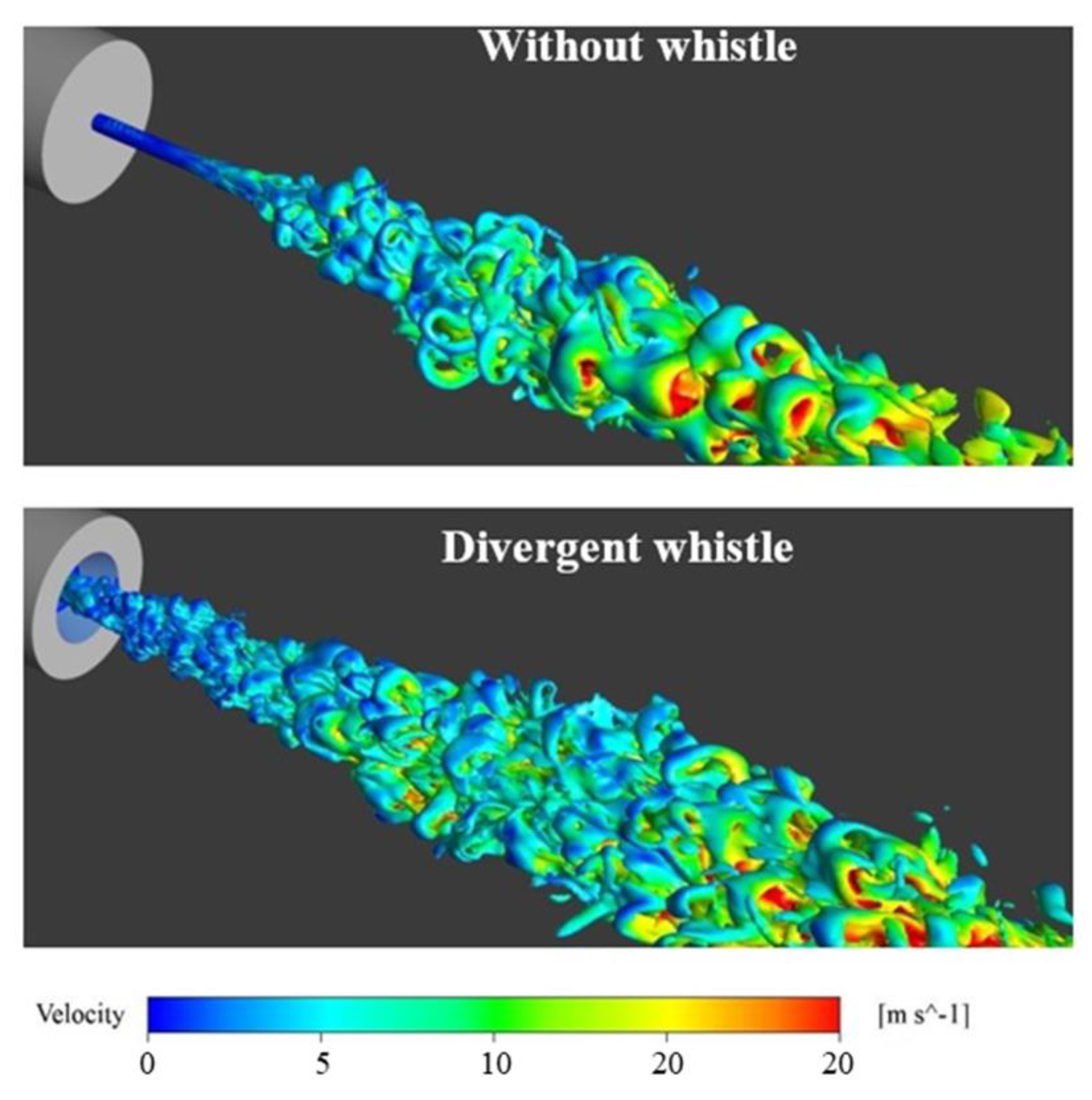
4.3. Numerical Calculation of Vorticity Field

In order to directly reflect the influence of different outlet shapes on the jet flow field. Figure 12 shows the three-dimensional shape of vorticity near the outlet of two nozzles. It can be seen from the comparison that the jet vorticity of two nozzles is significantly different. Near the nozzle outlet, the vorticity iso-surface of the nozzle without a whistle is a relatively smooth cylindrical structure and there are relatively weak fluctuations on the surface, corresponding to the transition process of the outflow. The divergent whistle nozzle jet has a complete turbulent structure at the outlet. The vortex scale near the outlet is small, and the small-scale vortex continuously entrains the surrounding fluid and merges with it to form a larger-scale vortex in the process of moving downstream. On the whole, by comparing the vorticity of the two nozzle jets, it can be seen that the vorticity of the nozzle jet without a whistle is a large-scale vortex, which mainly occurs after the instability of the jet core area, while the vorticity of the divergent nozzle includes a variety of forms and scales, in which the small-scale vortex is formed by shearing and shedding in the whistle. Larger-scale vortices are generated in the entrainment process of mainstream and ambient fluids.
In order to further reveal the interaction between the vortex and the cavitation in the cavitation jet, the vorticity transport equation was introduced for the analysis, and its expression is as follows:
D ω D t = ( ω ) v ω ( v ) + ρ m × p ρ m 2 + ( v m + v t ) 2 ω
where, the left side of the equation represents the change rate of the vorticity tensor with time, and the right side of the equation is composed of four terms in total, among which the first term represents the vortex extension caused by the velocity gradient; the second term is the vortex expansion caused by volume expansion and contraction, representing the effect of the compressibility of the fluid on vorticity; the third term is the baroclinic term caused by pressure and density gradients; the fourth term represents the vorticity change caused by viscous dissipation.
Figure 13a shows the volume fraction distribution of the jet cavitation of two kinds of organ pipe nozzles. By observing the cavitation morphology at the nozzle outlet, it can be found that the organ pipe nozzle without a whistle has a smooth tubular cavitation layer near the throat outlet, in which the cavitation begins to diffuse at the position x = 5 mm downstream of the throat outlet, and then the diameter of the cavitation cloud increases rapidly and presents a vortex structure. The cavitation generated by the nozzle with a divergent nozzle begins to diffuse at the outlet of the throat tube. Although the diffusion at the outlet is slow, the thickness of the cavitation layer is obviously larger than that of the nozzle without whistle. The shape and position of the cavitation at the throat of each nozzle are almost the same, which are caused by the separation vortex formed by the sudden change of the size of the resonant cavity and the throat inlet, and the cavitation volume fraction gradually decreases from the throat inlet to the downstream section. The part that does not completely disappear when reaching the outlet of the throat forms the tubular vacuole layer described above.
According to the distribution of items in the vorticity transport equation, the region with a higher distribution of baroclinic terms corresponds to the region with a higher volume fraction of cavitation, and the expansion term of vorticity corresponds to the shedding of cavitation, while the main generation of vorticity in the cavitation jet is reflected in the extension term of vorticity. It can be found from Figure 13b that the area with a high vortex extension term mainly starts at the nozzle outlet about 10 mm downstream. This is because although the jet velocity at the nozzle outlet is high and there is a large velocity gradient in the shear layer, the thickness of the shear layer here is thin and the diameter of the core jet is small. On the whole, the vorticity extension term is not directly related to the spatial distribution of the volume fraction, but the size of the extension term reflects the speed of the local vortex growth, while for the cavitation jet, the vortex distribution is closely related to the development of cavitation. By comparing the distribution of the vorticity extension term values of the two nozzles near the nozzle outlet, it can be found that the nozzle without a whistle has a relatively smooth tubular distribution at the outlet, and the vorticity increment at this position mainly comes from the inner wall boundary layer of the nozzle. The increment of vorticity at the nozzle outlet of the nozzle with a divergent whistle is significantly higher than that of the nozzle without a whistle. In addition to the vorticity transmitted by convection inside the nozzle, the vorticity also increases at the periphery of the shear layer, indicating that the divergent whistle can promote the generation of vorticity near the nozzle outlet.

5. Conclusions

In this paper, a visualized experimental system of a high-pressure water cavitation jet was built. The unsteady characteristics of cavitation clouds of an organ pipe nozzle with different outlet shapes were studied based on high-speed photography. The dynamic characteristics of the cavitation cloud were extracted by the proper orthogonal decomposition method (POD), and the influence of nozzle outlet shapes on the cavitation performance of the organ pipe was analyzed based on an unsteady numerical simulation. From the analysis of the results, the following conclusions can be drawn:
(1)
The proper orthogonal decomposition method (POD) can effectively reflect the dynamic characteristics of the cavitation jet. The reconstruction coefficients of mode-1 obtained by the POD can better reflect the periodic time-frequency characteristics of cavitation development.
(2)
The shape of the nozzle outlet has a great influence on the dynamic characteristics of cavitation. When the nozzle outlet has a divergent segment, the periodic oscillation characteristics are more obvious, the frequency domain distribution is more concentrated, and the cavitation near the nozzle outlet is more intense.
(3)
The jet generated by the nozzle with a divergent whistle has a larger vorticity in the shear layer near the outlet. Further, a stronger small-scale vortex and more severe cavitation occurs from the nozzle with a divergent whistle.
(4)
The region with a higher distribution of baroclinic terms corresponds to the region with a higher volume fraction of cavitation. The expansion term of vorticity corresponds to the shedding of cavitation, while the main generation of vorticity in the cavitation jet is reflected in the extension term of vorticity.
More experimental and numerical studies will be required in the future, such as using particle image velocimetry (PIV) to visualize the flow field characteristics of the jet and reveal the interference of the vortex with the jet, or study how flares affect the oscillation mechanism and improve the nozzle design theory.

Author Contributions

Conceptualization, G.W., Y.Y. and W.S.; Formal analysis, G.W., Y.Y. and C.W.; Investigation, B.P.; Data curation, W.L.; Writing—original draft preparation, G.W., Y.Y. and C.W.; Writing—review and editing, W.S. and W.L.; Visualization, B.P.; Supervision, Y.Y., W.S. and W.L.; Project administration, W.S. and W.L. All authors have read and agreed to the published version of the manuscript.

Funding

This research was funded by the National Key Research and Development Project of China (no. 2019YFB 2005300), National High-Tech Ship Scientific Research Project of China (no. MIIT [2019] 360), National Natural Science Foundation of China (no. 51979138), National Natural Science Foundation of China (No. 51979240), Jiangsu Natural Science Re-search Project (no. 19KJB470029), Jiangsu Water Conservancy Science and Technology Project (no. 2019038), and Nantong Science and Technology Project (no. JC2019155).

Institutional Review Board Statement

Not applicable.

Informed Consent Statement

Not applicable.

Data Availability Statement

Data on the analysis and reporting results during the study can be obtained by contacting the authors.

Conflicts of Interest

The authors declare no conflict of interest.

References

  1. Soyama, H. Cavitating Jet: A Review. Appl. Sci. 2020, 10, 7280. [Google Scholar] [CrossRef]
  2. Soyama, H. Cavitation Peening: A Review. Metals 2020, 10, 270. [Google Scholar] [CrossRef] [Green Version]
  3. Wang, H.L.; Hu, Q.X.; Yang, Y.; Wang, C. Performance Differences of Electrical Submersible Pump under Variable Speed Schemes. Int. J. Simul. Model. 2021, 20, 76–86. [Google Scholar] [CrossRef]
  4. Zhou, J.; Zhao, M.; Wang, C.; Gao, Z. Optimal Design of Diversion Piers of Lateral Intake Pumping Station Based on Orthogonal Test. Shock. Vib. 2021, 2021, 6616456. [Google Scholar] [CrossRef]
  5. Tang, S.; Zhu, Y.; Yuan, S. An improved convolutional neural network with an adaptable learning rate towards multi-signal fault diagnosis of hydraulic piston pump. Adv. Eng. Inform. 2021, 50, 101406. [Google Scholar] [CrossRef]
  6. Zhu, Y.; Li, G.; Wang, R.; Tang, S.; Su, H.; Cao, K. Intelligent fault diagnosis of hydraulic piston pump combining improved LeNet-5 and PSO hyperparameter optimization. Appl. Acoust. 2021, 183, 108336. [Google Scholar] [CrossRef]
  7. Shi, L.; Zhu, J.; Tang, F.; Wang, C. Multi-Disciplinary Optimization Design of Axial-Flow Pump Impellers Based on the Approximation Model. Energies 2020, 13, 779. [Google Scholar] [CrossRef] [Green Version]
  8. Wang, H.; Long, B.; Wang, C.; Han, C.; Li, L. Effects of the Impeller Blade with a Slot Structure on the Centrifugal Pump Performance. Energies 2020, 13, 1628. [Google Scholar] [CrossRef]
  9. Zhang, L.; Wang, C.; Zhang, Y.; Xiang, W.; He, Z.; Shi, W. Numerical study of coupled flow in blocking pulsed jet impinging on a rotating wall. J. Braz. Soc. Mech. Sci. Eng. 2021, 43, 508. [Google Scholar] [CrossRef]
  10. Wang, H.; Qian, Z.; Zhang, D.; Wang, T.; Wang, C. Numerical Study of the Normal Impinging Water Jet at Different Impinging Height, Based on Wray–Agarwal Turbulence Model. Energies 2020, 13, 1744. [Google Scholar] [CrossRef] [Green Version]
  11. Ljiri, M.; Shimonishi, D.; Nakagawa, D.; Yoshimura, T. New water jet cavitation technology to increase number and size of cavitation bubbles and its effect on pure Al surface. Int. J. Lightwght Mater. Manuf. 2018, 1, 12–20. [Google Scholar]
  12. Yang, Y.; Li, W.; Shi, W.; Wang, C.; Zhang, W. Experimental Study on Submerged High-Pressure Jet and Parameter Optimization for Cavitation Peening. Mechanika 2020, 26, 346–353. [Google Scholar] [CrossRef]
  13. Yang, Y.; Li, W.; Shi, W.; Zhou, L.; Zhang, W. Experimental Study on the Unsteady Characteristics and the Impact Performance of a High-Pressure Submerged Cavitation Jet. Shock. Vib. 2020, 2020, 1701843. [Google Scholar] [CrossRef]
  14. Yang, Y.; Li, W.; Shi, W.; Zhang, W.; AEl-Emam, M. Numerical Investigation of a High-Pressure Submerged Jet Using a Cavitation Model Considering Effects of Shear Stress. Processes 2019, 7, 541. [Google Scholar] [CrossRef] [Green Version]
  15. Watanabe, R.; Kikuchi, T.; Yamagata, T.; Fujisawa, N. Shadowgraph Imaging of Cavitating Jet. J. Flow Control. Meas. Vis. 2015, 3, 106–110. [Google Scholar] [CrossRef] [Green Version]
  16. Watanabe, R.; Yanagisawa, K.; Yamagata, T.; Fujisawa, N. Simultaneous shadowgraph imaging and acceleration pulse measurement of cavitating jet. Wear 2016, 358, 72–79. [Google Scholar] [CrossRef]
  17. Peng, C.; Tian, S.; Li, G. Joint experiments of cavitation jet: High-speed visualization and erosion test. Ocean Eng. 2018, 149, 1–13. [Google Scholar] [CrossRef]
  18. Shridhar, G.J.; Katz, O.K. Near-field flow structure and cavitation inception in jets. In Proceedings of the First Symposium on Turbulence and Shear Flow Phenomena, San Francisco, CA, USA, 18–23 July 1999. [Google Scholar]
  19. Nakano, K.; Hayakawa, M.; Fujikawa, S. Observations of Cavitation Bubbles in a Starting Submerged Water Jet. Trans. Jpn. Soc. Mech. Eng. Ser. B 2003, 69, 360–367. [Google Scholar] [CrossRef] [Green Version]
  20. McGinn, P.; Pearce, D.; Hardalupas, Y.; Taylor, A.; Vogiatzaki, K. Cavitation Bubble Cloud Break-Off Mechanisms at Micro-Channels. Fluids 2021, 6, 215. [Google Scholar] [CrossRef]
  21. Ma, R.; Slaboch, P.E.; Morris, S.C. Fluid mechanics of the flow-excited Helmholtz resonator. J. Fluid Mech. 2009, 623, 1–26. [Google Scholar] [CrossRef]
  22. Hussain, A.; Hasan, M. The ’whistler-nozzle’ phenomenon. J. Fluid Mech. 1983, 134, 431–458. [Google Scholar] [CrossRef] [Green Version]
  23. Varieras, D.; Brancher, P.; Giovannini, A. Self-sustained oscillations of a confined impinging jet. Flow Turbul. Combust. 2006, 78, 1–15. [Google Scholar] [CrossRef]
  24. Favrel, A.; Junior JG, P.; Landry, C.; Müller, A.; Yamaishi, K.; Avellan, F. Dynamic modal analysis during reduced scale model tests of hydraulic turbines for hydro-acoustic characterization of cavitation flows. Mech. Syst. Signal Process. 2018, 117, 81–96. [Google Scholar] [CrossRef]
  25. Fujisawa, N.; Fujita, Y.; Yanagisawa, K.; Fujisawa, K.; Yamagata, T. Simultaneous observation of cavitation collapse and shock wave formation in cavitating jet. Exp. Therm. Fluid Sci. 2018, 94, 159–167. [Google Scholar] [CrossRef]
  26. Peng, K.; Tian, S.; Li, G.; Huang, Z.; Yang, R.; Guo, Z. Bubble dynamics characteristics and influencing factors on the cavitation collapse intensity for self-resonating cavitating jets. Pet. Explor. Dev. 2018, 45, 155–162. [Google Scholar] [CrossRef]
  27. Sato, K.; Taguchi, Y.; Hayashi, S. High Speed Observation of Periodic Cavity Behavior in a Convergent-Divergent Nozzle for Cavitating Water Jet. J. Flow Control. Meas. Vis. 2013, 1, 102–107. [Google Scholar] [CrossRef] [Green Version]
  28. Peng, G.; Wakui, A.; Oguma, Y.; Shimizu, S.; Ji, H. Periodic Behavior of Cavitation Cloud Shedding in Submerged Water Jets Issuing from a Sheathed Pipe Nozzle. J. Flow Control. Meas. Vis. 2018, 6, 15–26. [Google Scholar] [CrossRef] [Green Version]
  29. Peng, G.; Yang, C.; Oguma, Y.; Shimizu, S. Numerical analysis of cavitation cloud shedding in a submerged water jet. J. Hydrodyn. 2016, 28, 986–993. [Google Scholar] [CrossRef]
  30. Peng, G.; Okada, K.; Yang, C.; Oguma, Y.; Shimizu, S. Numerical Simulation of Unsteady Cavitation in a High-speed Water Jet. Int. J. Fluid Mach. Syst. 2016, 9, 66–74. [Google Scholar] [CrossRef] [Green Version]
  31. Li, G.S.; Shen, Z.H.; Zhou, C.S.; Zhang, D.B.; Liao, H.L. Advances in Investigation and Application of Self-resonating Cavitating Water Jet. Eng. Sci. 2005, 7, 27–32. [Google Scholar]
  32. Jiang, Y.; Abu-Hamdeh, N.H.; Bantan, R.A.; Li, Z. Influence of upstream angled ramp on fuel mixing of hydrogen jet at supersonic cross flow. Aerosp. Sci. Technol. 2021, 119, 107099. [Google Scholar] [CrossRef]
  33. Jiang, Y.; Poozesh, A.; Marashi, S.M.; Moradi, R.; Gerdroodbary, M.B.; Shafee, A.; Li, Z.; Babazadeh, H. Effect of cavity back height on mixing efficiency of hydrogen multi-jets at supersonic combustion chamber. Int. J. Hydrogen Energy 2020, 45, 27828–27836. [Google Scholar] [CrossRef]
  34. Jiang, Y.; Gerdroodbary, M.B.; Sheikholeslami, M.; Babazadeh, H.; Shafee, A.; Moradi, R.; Li, Z. Effect of free stream angle on mixing performance of hydrogen multi-jets in supersonic combustion chamber. Int. J. Hydrogen Energy 2020, 45, 25426–25437. [Google Scholar] [CrossRef]
  35. Kosambi, D.D. Statistics in Function Space. J. Indian Math. Soc. 2016, 115–123. [Google Scholar] [CrossRef]
  36. Brennen, C.E. Fundamentals of Multiphase Flow; Cambridge University Press: Cambridge, UK, 2005. [Google Scholar]
  37. Mikko, M.; Veikko, T.; Sirpa, K. On the Mixture Model for Multiphase Flow; VTT Publications: Espoo, Finland, 1996; p. 288. [Google Scholar]
  38. Zwart, P.J.; Gerber, A.G.; Belamri, T. A Two-Phase Flow Model for Predicting Cavitation Dynamics. In Proceedings of the Fifth International Conference on Multiphase Flow, Yokohama, Japan, 30 May–3 June 2004. [Google Scholar]
  39. Deck, S. Recent improvements in the Zonal Detached Eddy Simulation (ZDES) formulation. Theor. Comput. Fluid Dyn. 2012, 26, 523–550. [Google Scholar] [CrossRef]
Figure 1. Test platform for high-pressure submerged jet. (a) Cavitation jet system. (b) Physical photographs of the test stand.
Machines 10 00004 g001
Figure 2. Geometry structure of the nozzles used in experiment. (a) Organ pipe nozzle (without whistle). (b) Organ pipe nozzle (divergent whistle).
Machines 10 00004 g002
Figure 3. Calculation domain of the submerged jet.
Machines 10 00004 g003
Figure 4. Mesh of calculation domain.
Machines 10 00004 g004
Figure 5. Cavitation cloud image of organ pipe nozzle with divergent whistle.
Machines 10 00004 g005
Figure 6. Spatial distribution of mode_0 to mode_7 of cavitation bubbles.
Machines 10 00004 g006
Figure 7. Time coefficients of the modes in time and frequency domains. (a) The first four modulus time coefficients. (b) Frequency-domain plots of time coefficients.
Machines 10 00004 g007
Figure 8. Cavitation cloud morphology of two nozzles. (a) Organ pipe nozzle without whistle. (b) Organ pipe nozzle with divergent whistle.
Machines 10 00004 g008
Figure 9. Time- and frequency-domain plots of cavitation cloud by nozzles with different outlet shapes. (a) Time-domain plot. (b) Frequency-domain plot.
Machines 10 00004 g009
Figure 10. Time-domain distribution for mode_1 of the cavitating jet images. (a) Cavitating jet by nozzle without whistle. (b) Cavitating jet by nozzle with divergent whistle.
Machines 10 00004 g010
Figure 11. Frequency-domain distribution for mode_1 of the cavitating jet images. (a) Cavitating jet by nozzle without whistle. (b) Cavitating jet by nozzle with divergent whistle.
Machines 10 00004 g011
Figure 12. Vorticity iso-surface of the jet with different nozzles.
Machines 10 00004 g012
Figure 13. Different turns of vorticity transport equations of different nozzles. (a) Cavity volume fraction. (b) Vorticity extension term. (c) Vorticity expansion term. (d) Vorticity baroclinic term.
Machines 10 00004 g013
Table 1. The design parameters of the nozzles.
L1 (mm)L2 (mm)d (mm)L3 (mm)θ (°)
541460
Table 2. The main frequency position at different pressures.
Pressure (MPa)2610141820
Frequency without whistle (Hz)400022501500125011001000
Frequency with divergent whistle (Hz)260018001400130012001100
Publisher’s Note: MDPI stays neutral with regard to jurisdictional claims in published maps and institutional affiliations.

