Article

Magnetite and Carbon Extraction from Coal Fly Ash Using Magnetic Separation and Flotation Methods

1
I.P. Bardin Laboratory for Problems of Metallurgy for Complex Ores, A.A. Baikov Institute of Metallurgy and Materials Science, Russian Academy of Science, Leninsky prosp., 49, Moscow 119334, Russia
2
Laboratory No. 4.2. Complex processing of non-traditional mineral materials, Research Institute of Comprehensive Exploitation of Mineral Resources-IPKON, Russian Academy of Sciences, Kryukovskii tupik 4, Moscow 111020, Russia
3
Laboratory of Material Diagnostics, A.A. Baikov Institute of Metallurgy and Materials Science, Russian Academy of Science, Leninsky prosp., 49, Moscow 119334, Russia
4
Faculty of Technology of Inorganic Substances and High-Temperature Materials, D. Mendeleev University of Chemical Technology of Russia, Mjusskaja square, 9, Moscow 125047, Russia
5
School of Metallurgical and Materials Engineering, Jiangsu University of Science and Technology, Zhangjiagang Campus, Zhangjiagang 215600, China
*
Author to whom correspondence should be addressed.
Minerals 2019, 9(5), 320; https://doi.org/10.3390/min9050320
Submission received: 16 April 2019 / Revised: 20 May 2019 / Accepted: 23 May 2019 / Published: 25 May 2019
(This article belongs to the Section Mineral Processing and Extractive Metallurgy)

Abstract

:
In this study, enrichment methods for coal fly ash (CFA) from Omsk thermal power station No. 4 (TPS-4) were investigated. The magnetite and unburned carbon concentrates were obtained by magnetic separation and flotation methods. The wet magnetic separation used in the study increased the magnetite content in the magnetic fraction from 10.48 to 12.72 wt % compared to dry magnetic separation. The XRD analysis showed that the magnetic fraction primarily consists of magnetite, mullite, and quartz. The SEM analysis demonstrated that magnetite is located primarily on the surface of alumosilicate spheres and has three types of shape: dendritic structures, hexagonal bulk agglomerates, and star-like structures. For the flotation tests, a low-price diesel was used as the collector. It was found that, if CFA particles of 40–71 µm are used, ~99% of unburned carbon can be recovered. It was also found by SEM that, if CFA particles of 71–100 µm are used, alumosilicates on a carbon surface prevent complete interaction of diesel with carbon particles and decrease thereby carbon recovery to 83%.

1. Introduction

Annually ~230 thousand tons of coal fly ash (CFA) are generated at thermal power station No. 4 (TPS-4) in Omsk after burning coal from the Ekibastuz deposit, Republic of Kazakhstan [1]. Since this CFA is not being utilized, it is stored on disposal sites near the Irtysh River. This river may be polluted in summer time after dust storms when disposal sites become dry. Agricultural areas located near the disposal sites can also be polluted, which makes them unsuitable for further use. CFA recycling, in addition to reducing the anthropogenic impact on nature, will enable the use of this type of waste as a raw material in the metallurgy, chemical, and construction industries for recovering valuable materials [2,3].
The Omsk CFA mainly contains 20–35 wt % alumina, 50–65 wt % silica, 5–15 wt % magnetite, and up to 6 wt % unburned carbon [1,2]. Previous research was aimed mainly at studying methods for producing alumina [3,4,5,6], ceramics [7,8,9,10], coagulants [11,12], and the extraction of the rare-earth elements [13,14,15,16,17]. Our previous research was about the leaching of alumosilicates with hydrochloric acid for further production of alumina [18]. Silicon oxide does not practically react with hydrochloric acid, but 90–95% of iron oxide goes into the solution if using the autoclave leaching method. Further purification of the solution from FeCl3 to obtain pure aluminum oxide is a very complicated process [19,20,21]. Therefore, the maximum removal of magnetite from alumosilicate is an essential task.
Depending on the storage methods, CFA may be of the dry type that is caught immediately after burning coal in special separators. CFA of the wet type is obtained after transporting the disposal sites using water. Therefore, in this paper, two methods of magnetic separation of the Omsk CFA are studied: dry and wet.
Unburned carbon is considered to be a harmful impurity if using CFA as an additive to cement [22]. Therefore, separation of carbon concentrate into a separate fraction will allow obtaining a product for secondary use at TPS-4 and maximally purify the alumosilicate part of the CFA for further treatment. One of the most promising methods for recovering unburned carbon from CFA is the froth flotation. This method is based on the separation of hydrophobic materials from hydrophilic ones [23]. In this study, the flotation process will be investigated using a diesel fuel as a collector.
The purpose of the present paper is to investigate the maximum separation of magnetite and unburned carbon from the alumosilicate fraction of the Omsk CFA.

2. Materials and Methods

2.1. Materials

Raw CFA samples were collected from the Omsk TPS-4 ash residue storage (55.129231, 73.167497). Diesel fuel (PJSC Lukoil Oil Company, Moscow, Russia) and methylisobutylcarbinol (C6H14O), CAS No. 108-11-2, (Merck, Russia) were used in the present study. The chemical composition of the raw CFA is presented in Table 1.

2.2. Analysis Methods

The X-ray diffraction (XRD) analysis of raw CFA (Figure 1) and non-magnetic fraction were carried out using a Dron-3M diffractometer (Burevestnik, St. Petersburg, Russia) in a range of angles 2θ 10–110° at 0.1° intervals with a Cu-Kα radiation source. The operating mode of the X-ray source was set to 50 kW/30 mA. The magnetic fraction XRD was carried out with a Co-Kα radiation source in a range of angles 2θ 10–110° at 0.1° intervals. The operating mode of the X-ray source was set to 40 kW/30 mA.
The chemical composition of CFA samples was analyzed using X-ray fluorescence (XRF) spectrometry on a ZXS Primus II (Rigaku, Tokyo, Japan) and using an atomic emission spectrometer with inductively coupled plasma ICAP 6300 DUO (Thermo Scientific, St. Petersburg, Russia). Analysis of surface morphology and microstructure of CFA samples was carried out using scanning electron microscopy (SEM) with a JSM-6510LV microscope (JEOL, Tokyo, Japan).
The carbon content was determined by a gas analyzer СS-600 (LECO Corporation, Saint Joseph, MI, USA). Samples (~0.1 g) were placed in ceramic crucibles with a mixture of tungsten, iron, and tin metals as a flux and then loaded into an induction furnace. The carbon concentration was determined by infrared absorption of gaseous CO2 during sample combustion in an oxygen atmosphere.

2.3. Equipment

A roll-type dry PBSts 22/8 (Magnetit LLC, Russia) and wet MBS 150 × 125 (NPO Erga, Russia) magnetic separators were used to separate the magnetic and non-magnetic fractions of CFA.
Carbon flotation tests were carried out in an 189FL flotation machine (REC Mekhanobr-Tekhnika, Russia).

2.4. Magnetic Separation

For dry separation, 200 g of CFA was used for one test. The applied magnetic intensities were 0.13 and 0.26 T. For wet separation, CFA samples of 100 g were mixed up with water and loaded into the separator. The applied magnetic intensities varied from 0.06 to 0.11 T.

2.5. Flotation

For flotation tests, methylisobutylcarbinol (MIBC) was used as a frother, and diesel fuel was used as a collector. Typical amounts of the non-magnetic fraction and water volume were 100 g and 500 mL, respectively. The particle size for flotation was selected to be within the 71–100 µm range. Preparation of the collector water emulsion was carried out as follows: 4.1 mL of diesel (ρ = 0.82 g/cm3) was placed in a 50 mL flask, topped up with distilled water, and mixed thoroughly by ultrasound for 5 min using an Sonorex Digitec ultrasound bath (Bandelin Electronic, Germany). The diesel concentration was 100 g/L, and the volume of the emulsion added to the pulp was 0.5, 1.0, 3.0, 5.0, and 10.0 mL. Preparation of the frother was carried out as follows: 0.93 mL of MIBC (ρ = 0.806 g/cm3) was placed in a 50 mL flask and topped up with distilled water. The volume of the frother added to the pulp was 4 mL, while the MIBC concentration in water during flotation was 0.33 g/L.
Flotation tests were carried out as follows: non-magnetic fractions and water were loaded into a flotation chamber, mixed for 4 min, then mixed with the collector for 3 min, mixed with the frother for 3 min, and finally floated until the froth mineralization stopped (~4 min). Flotation tailings and the carbon concentrate were first dried at T = 60 °C for 24 h and then weighed to determine the product output, and the carbon content was then analyzed. For flotation kinetic tests, the concentrates were collected at 30 s, 60 s, 90 s, 120 s, 180 s, and 240 s. The particle size for flotation was selected to be of 40–71 and 71–100 µm.

2.6. Equations

The recovery level (R) was calculated by following equation [24]:
R = [(γ × β)/α)] × 100%
where γ is the amount of the magnetite/carbon concentrate relative to the initial mass of the raw CFA; β is the magnetite/carbon grade in concentrate; α is the magnetite/carbon content in the raw CFA.
The magnetic separation and flotation efficiency index (E) was employed as an efficiency criterion [25]:
E = [(Rγ)/(100 − α)] × 100%.

3. Results and Discussion

3.1. Dry Magnetic Separation

As shown in Figure 1, the major phases of the raw CFA are mullite (3Al2O3·2SiO2), quartz (SiO2), and magnetite (Fe3O4). The SEM images of the raw CFA are shown in Figure 2. There were three types of particles: spheres, agglomerates of irregular shape, and porous structures. In previous research, it was shown that spheres consists of alumosilicates and magnetite crystals are located on its surface [26,27]. Agglomerates of irregular shape consist only of alumosilicates. The porous structures are carbon particles.
The dry magnetic separation for magnetite concentrate obtained was studied first. In the tests, two magnetic intensities (MI) were used: low-level (0.13 T) and high-level (0.26 T). As shown in Figure 3, then low-level MI was used, the major part of the raw CFA concentrates into the non-magnetic fraction (I). The yield of the magnetic fraction (I) was not more 0.54%. The recovery of magnetite did not exceed 0.47%. Magnetite content in the non-magnetic fraction decreased from 5.27 to 5.26 wt % (Table 2). Since the use of the low-level MI does not provide the effective separation of the CFA fractions, a high-level MI was used in further tests.
After first using a high-level MI, more than 35% of the raw CFA was separated to the magnetic fraction. Magnetite content in the magnetic fraction (II) increased from 9.27 to 10.48 wt % compared with the tests with the low-level MI. In the non-magnetic fraction (II), magnetite content decreased to 2.39 wt %. Magnetite and alumosilicate concentrates were directed to the second dry magnetic separation at a high-level MI. It can be seen that the alumina and silica content in the alumosilicate concentrate increased in 2 wt % compared to the raw CFA. The iron oxide content decreased to 2.32 wt %. The magnetite concentrate consists of 11.37 wt % magnetite. MnO2 occurs mainly in this fraction.

3.2. Wet Magnetic Separation

Wet magnetic separation was studied to increase magnetite content in the magnetic fraction. This method can provide more efficient separation of magnetite and decrease the yield of the magnetic fraction. As seen in Figure 4, increasing the magnetic intensity from 0.06 to 0.11 Т leads to an increase in yield of the magnetic fraction from 25 to 30%. The chemical compositions of the magnetic and non-magnetic fractions depending on magnetic intensity are shown in Table 3.
The increase in the magnetic intensity from 0.06 to 0.11 Т provided a significant increase in magnetite content up to 12.72 wt %. The recovery level also increases with increasing magnetic intensity. The maximum value of 73.16% was obtained at 0.11 T. Iron oxide content (2.03 wt %) was at the same level as in the case of dry magnetic separation. At the same time, there was a decrease in the content of alumina and silica from 26.58 and 61.65 wt % to 23.17 and 53.71 wt %, respectively. The average content of alumina in the non-magnetic fraction was ~28 wt %, and that of silica was ~65 wt %. Although the recovery level of magnetite by dry and wet separation is approximately the same (~73%), the best method is the wet magnetic separation, because the yield of magnetic concentrate was ~5% lower compared to the dry separation, and the magnetite content was up to 1 wt % higher.
According to the XRD analysis (Figure 5a), the non-magnetic fraction consists only of mullite and quartz. The magnetic fraction mainly contains magnetite and small amounts of mullite and quartz (Figure 5b).
The main part of magnetite is located on the surface of spheres with an average diameter of 60–80 µm (Figure 6). The form of magnetite agglomerates is very different. These can be dendritic structures 10–20 µm in length (Figure 6a), hexagonal bulk agglomerates with an effective size from 5 to 20 µm (Figure 6b), or stars consisting of 4–6 rays (Figure 6c), with each ray consisting of 10–15 submicron pyramidal crystals (Figure 6d).

3.3. Carbon Flotation of the Non-Magnetic Fraction of CFA

The non-magnetic fraction that was obtained after the wet magnetic separation and that contained 3 wt % carbon was used for the flotation tests. Yang et al. found that the most suitable particle size for flotation should be more than 71 µm [28]. Thus, the non-magnetic fraction particles 71–100 µm in size were used for flotation tests. Diesel was chosen as the collector of flotation due to its high effectivity and low price [29]. MIBC was used in flotation tests to prevent coalescence of air bubbles, to increase the force of adhesion of bubbles to floating carbon particles and to promote the formation of a stable foam on the surface of the pulp. The results of flotation tests are shown in Figure 7.
It can be seen that the yield of carbon concentrates was 10–14 wt %. The carbon content decreased from 23 to 18 wt % at the increase in the collector volume from 0.5 to 10 mL. The recovery level and efficiency index at carbon flotation was maximal if using 3 mL of diesel fuel. The recovery level was 92.27%, and the efficiency index was –80.59%. An increase in the diesel volume to 10 mL decreases the E and R to 55.34% and 45.64%, respectively. Figure 8 shows the SEM images of the carbon concentrate after flotation. There were two forms of carbon particles: porous spherical ones and non-hollow, elongated rectangular ones.
To investigate the effect of particle size to unburned carbon recovery, the flotation kinetics tests were studied. There were two types of size fraction used: 40–71 µm and 71–100 µm. As shown in Figure 9, after 120 s of flotation, the carbon recovery practically did not increase compared with the value after 240 s. The use of a 40–71 µm fraction provided a ~99% recovery of unburned carbon, while carbon recovery did not exceed 83% using larger particles of 71–100 µm.
This may be due to the fact that large particles of unburned carbon contain a large number of alumosilicates on their surface, which prevents the complete interaction of diesel with the surface of the carbon particle (Figure 10a). Fine particles practically do not contain alumosilicates on their surface (Figure 10b). They are completely covered by a collector and separate easily from the non-magnetic fraction during flotation.
After flotation kinetics tests, the unburned carbon concentrate contained ~20 wt % of carbon (Table 4). The yield of the concentrate was 14.23%. The non-magnetic fraction after flotation contains ~1 wt % carbon. The yield of the non-magnetic fraction was 85.77 wt %. The carbon concentrate can be reused for combustion in thermal power plants or as an additive in metallurgical processes, for example, when replacing coal or hydrogen flow in the reductive roasting of magnetite pellets and red mud at temperatures below 1000 °С [30,31,32].
Based on the results of research, the following flowsheet of the CFA enrichment process using wet magnetic separation and flotation is suggested (Figure 11). The flowsheet contains information about the yield, grade, the recovery level of magnetite to concentrate and the efficiency index of wet magnetic separation were 30.32 wt %, 12.72 wt %, 73.16 wt % and 45.22 wt %, respectively. The yield, grade, the recovery level of carbon to concentrate and the efficiency index of flotation were 6.19 wt %, 19.80 wt %, 40.47 wt % and 35.30 wt %, respectively.

4. Conclusions

This paper describes the Omsk CFA enrichment methods using the dry and wet magnetic separation and flotation processes to recovery magnetite and unburned carbon concentrates. The conclusions are as follows:
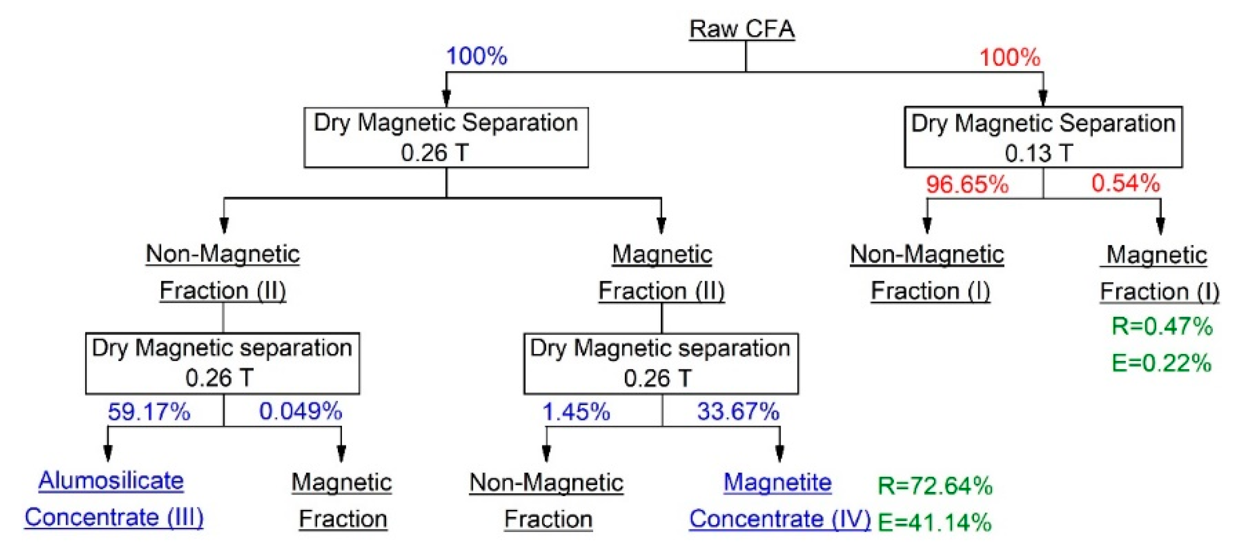
  • The dry magnetic separation of CFA with magnetic intensities at 0.26 T can provide a magnetite concentrate with a magnetite content of ~10.48 wt %.
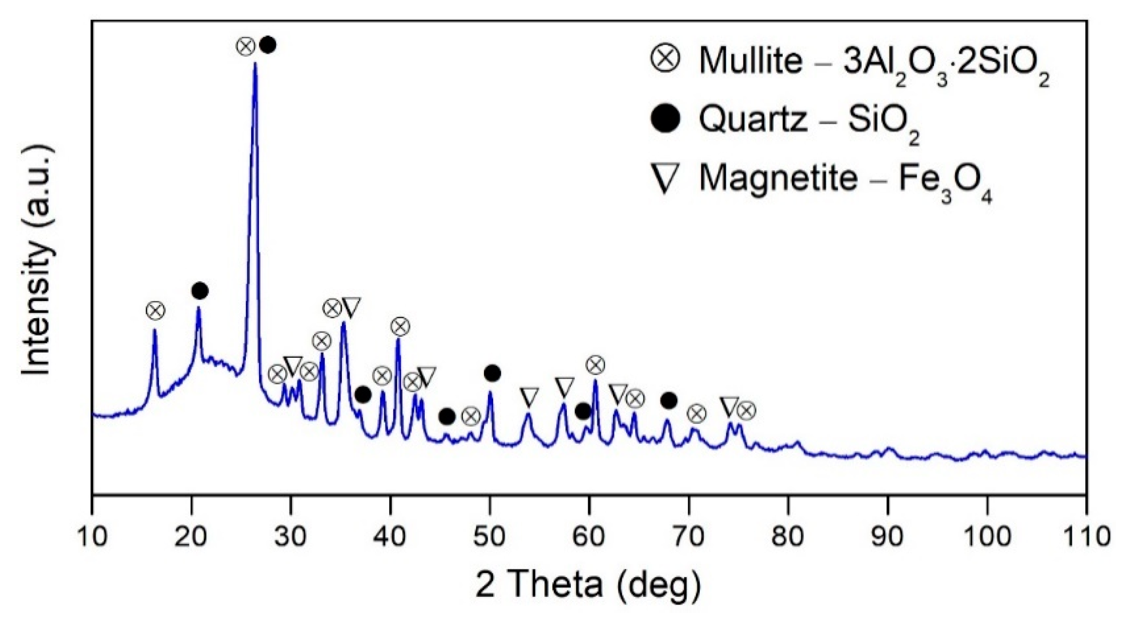
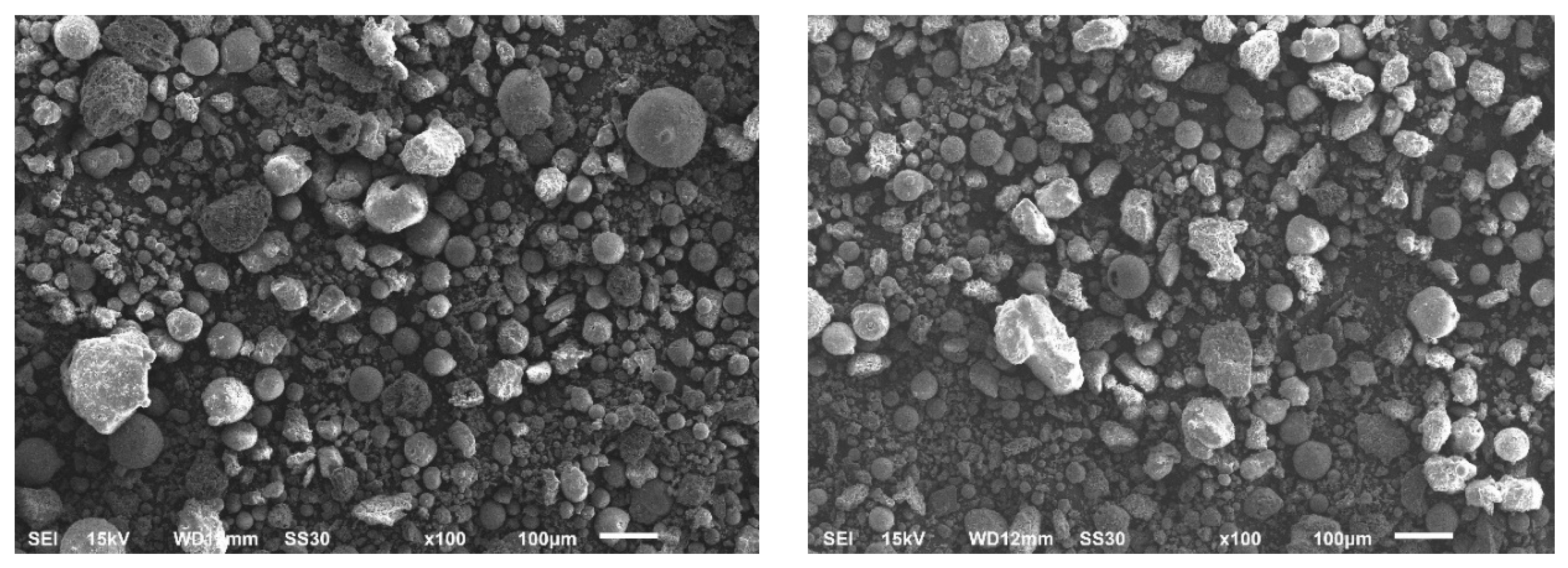
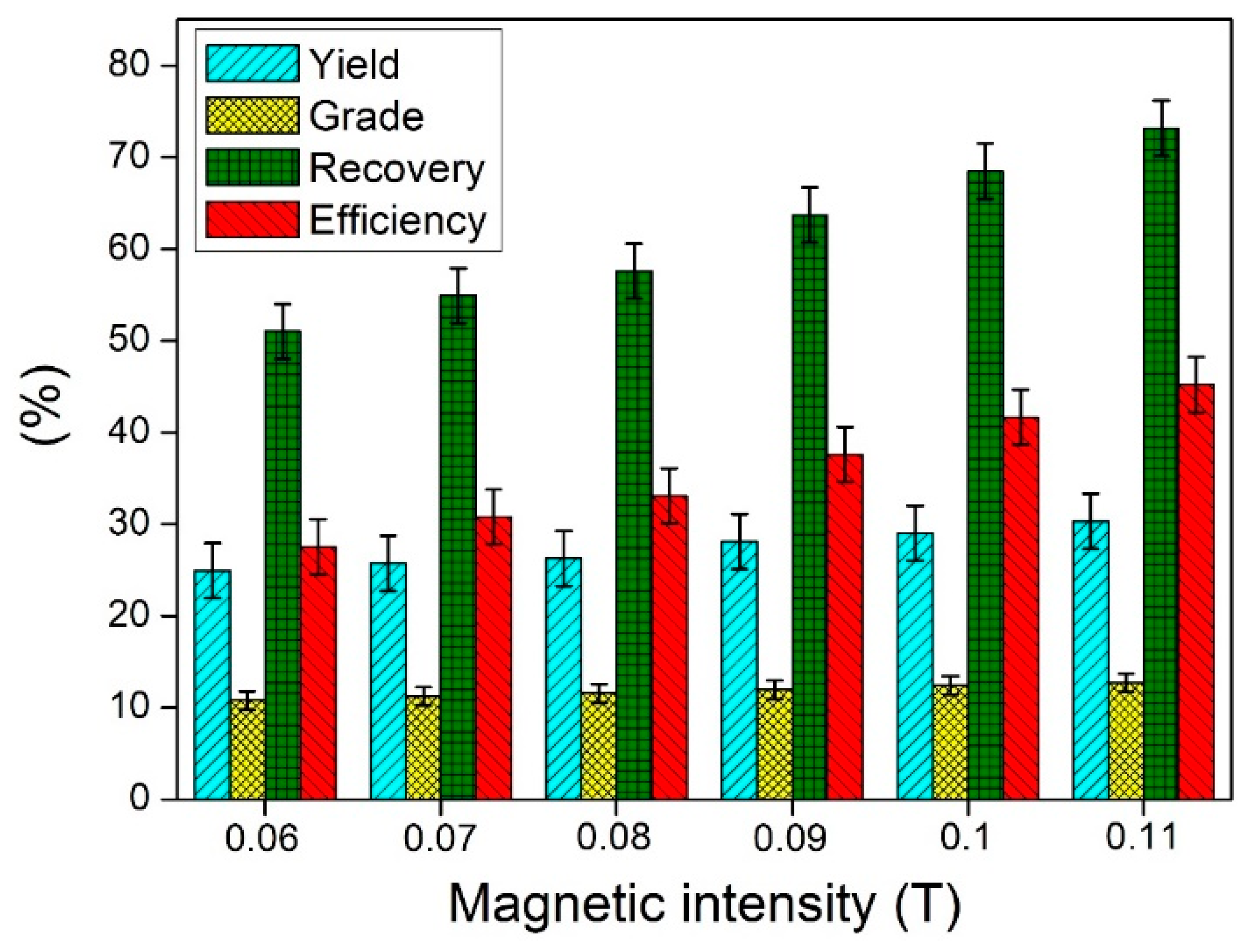
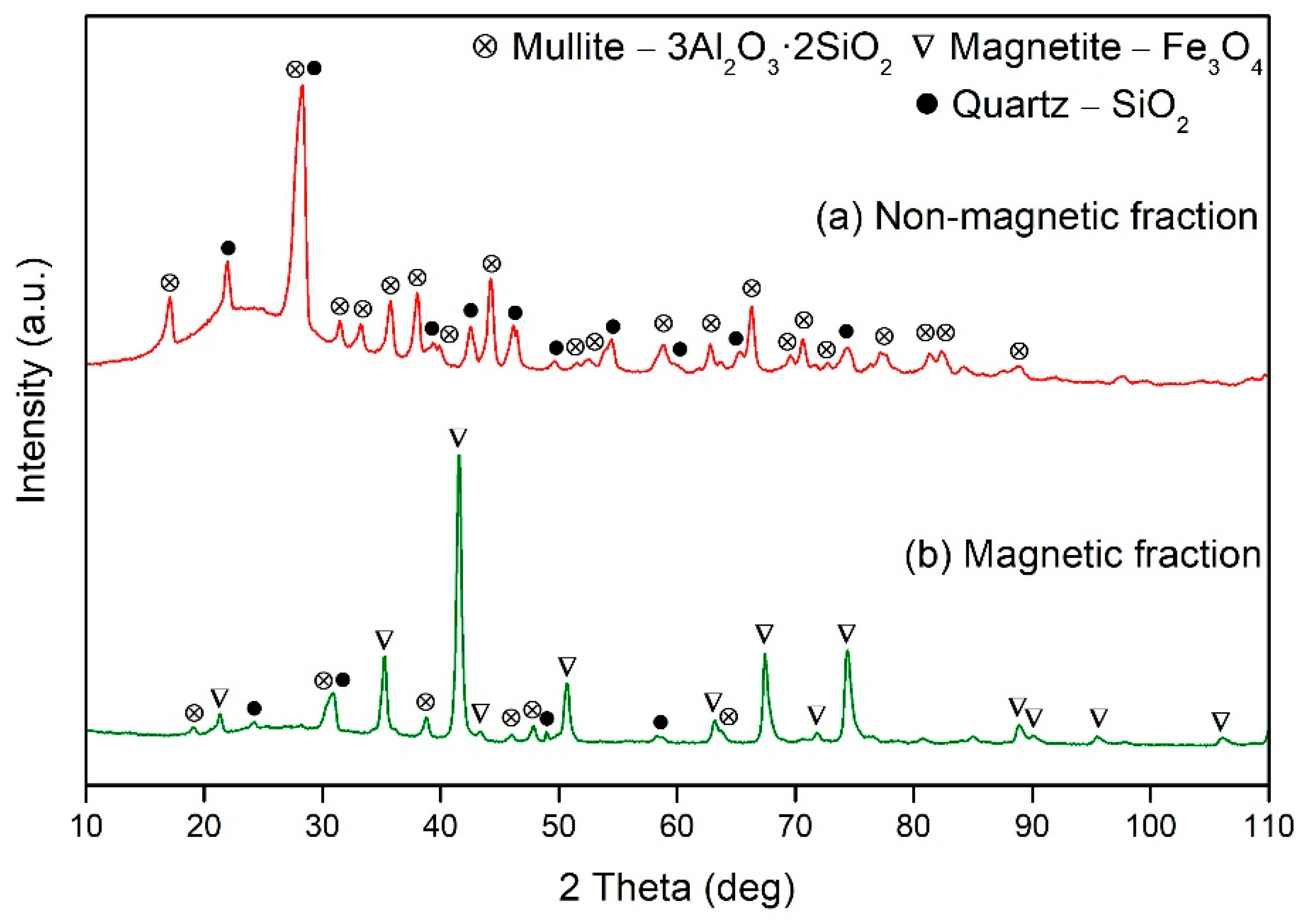
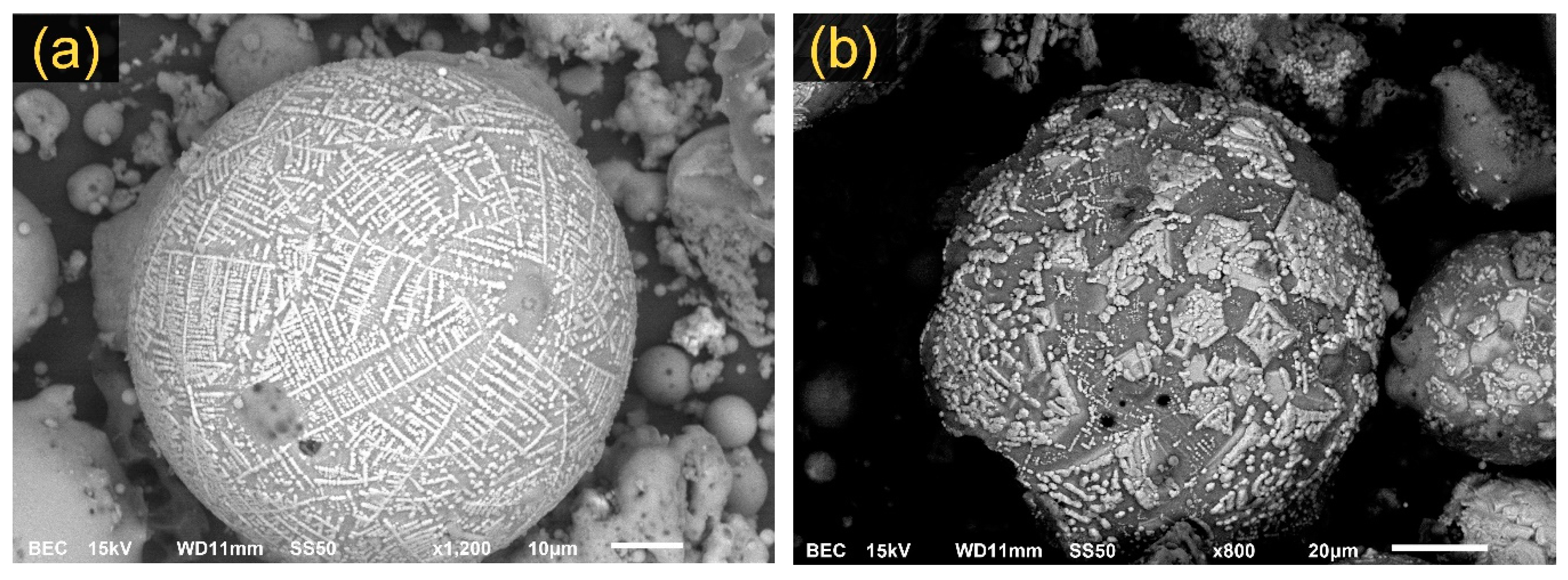
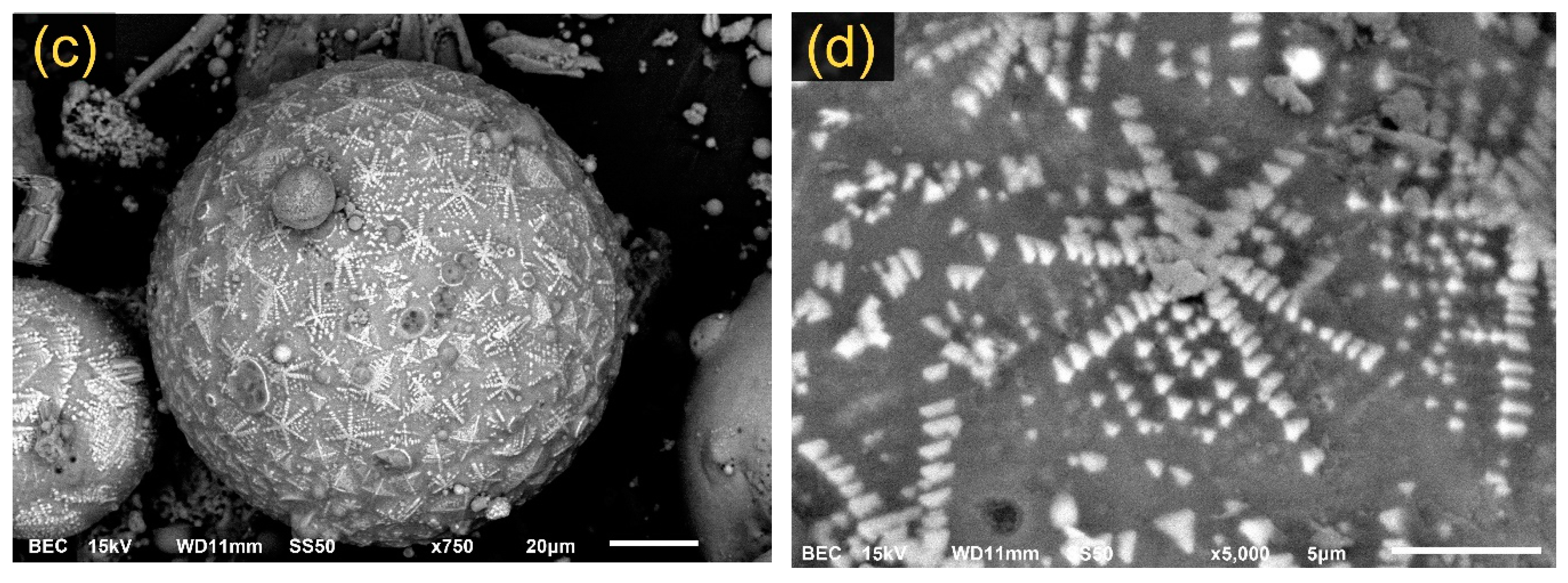
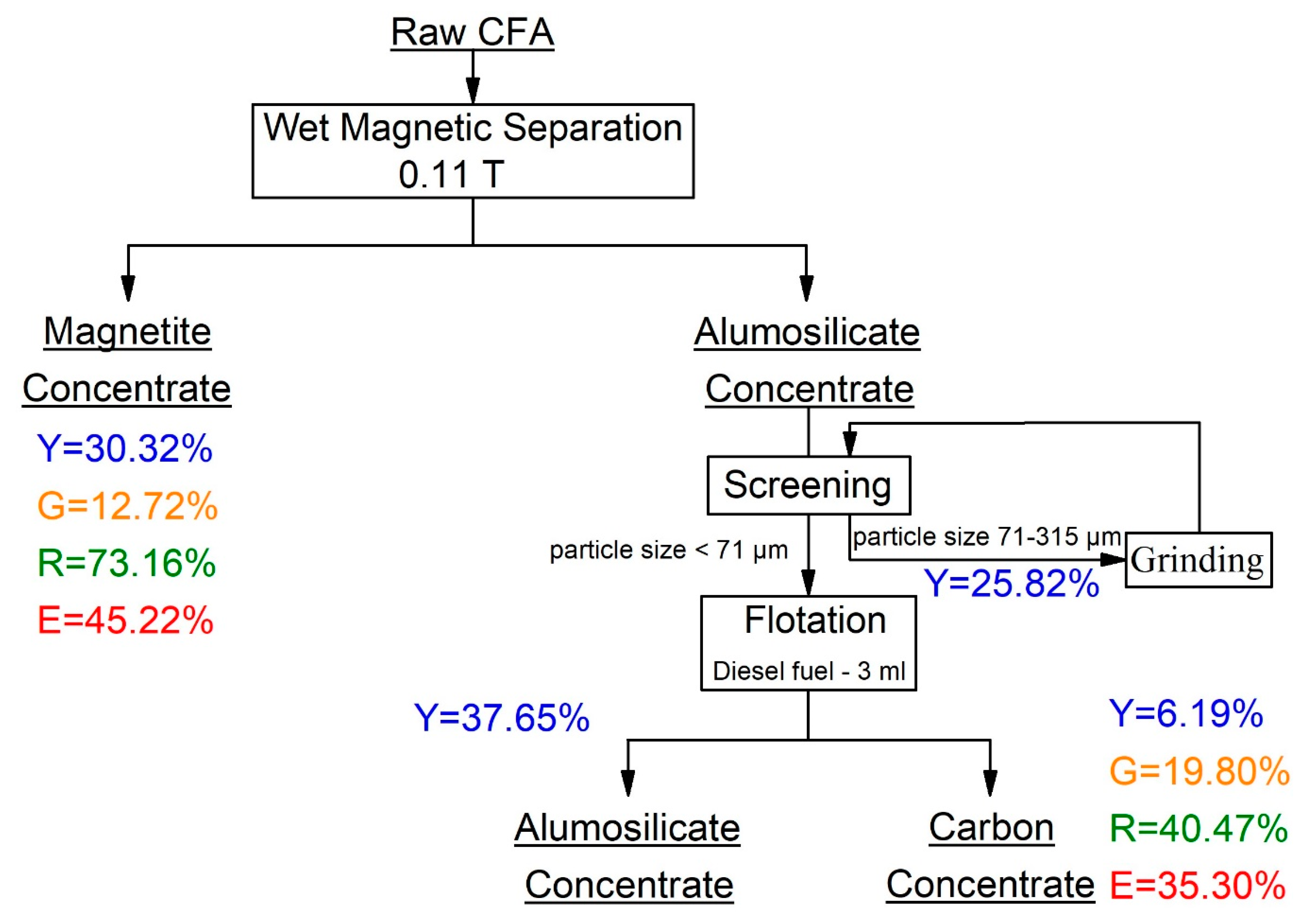
  • The magnetite content in the magnetic fraction after wet magnetic separation with magnetic intensities at 0.11 T increases from 5.27 to 12.72 wt %. The alumina content in the non-magnetic fraction increases from 26.5 to 28 wt %. The XRD analysis shows that magnetite concentrate consists mainly of magnetite, mullite, and quartz. The SEM images demonstrated that the magnetite crystals are located primarily on the surface of alumosilicate spheres and have three types of shape: dendritic structures, hexagonal bulk agglomerates, and star-like structures.
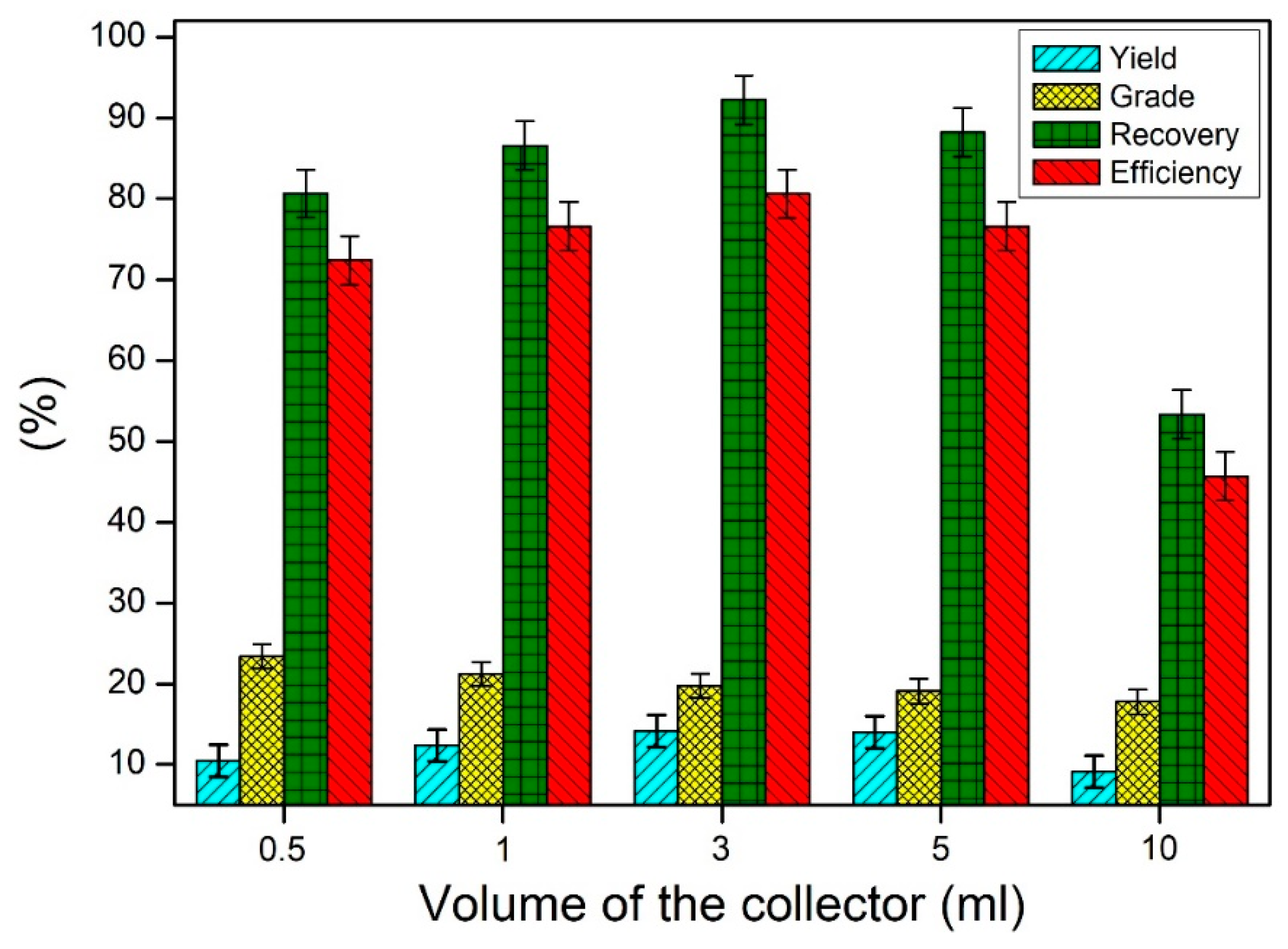
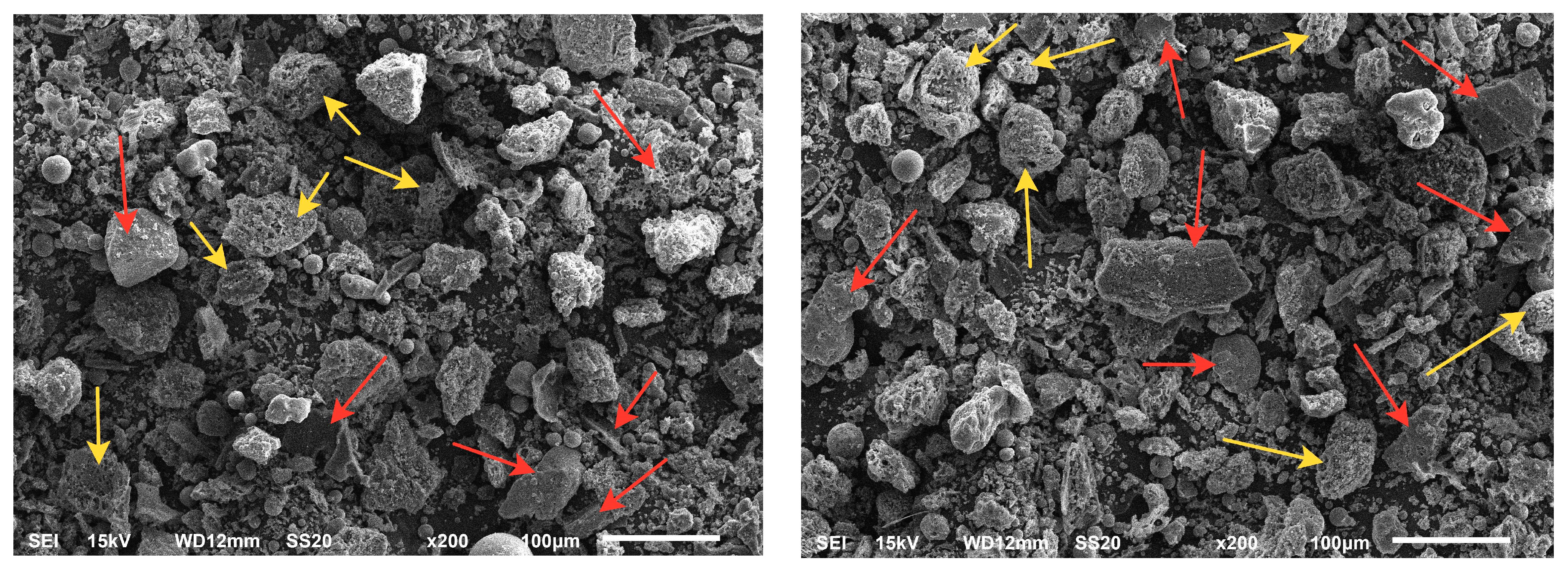
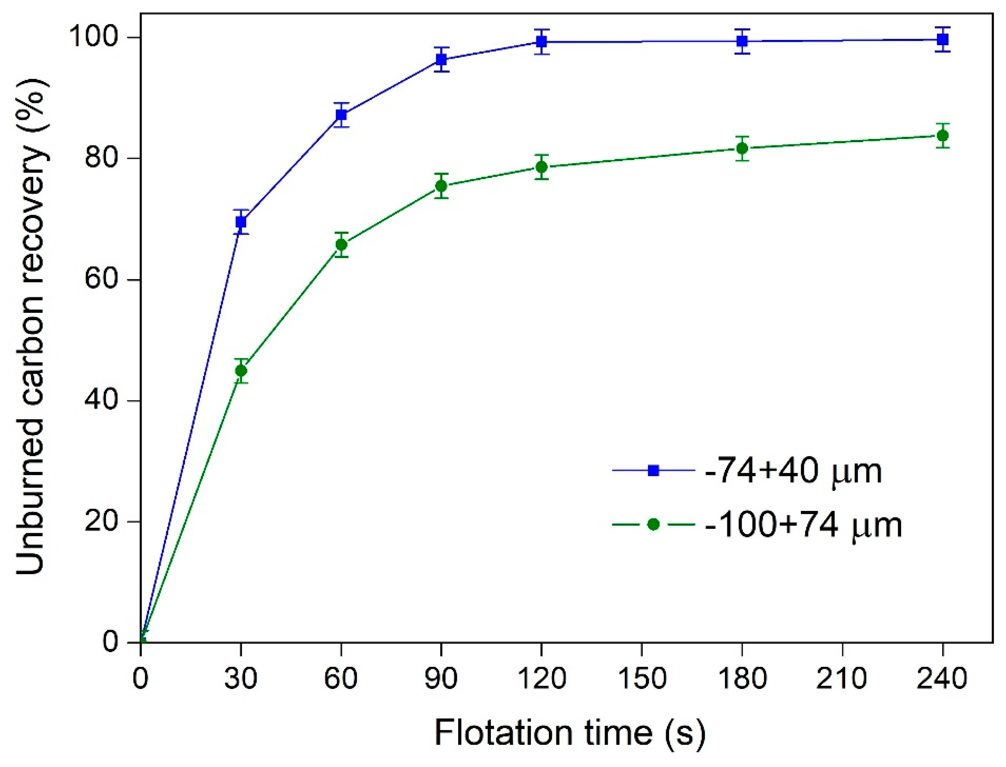
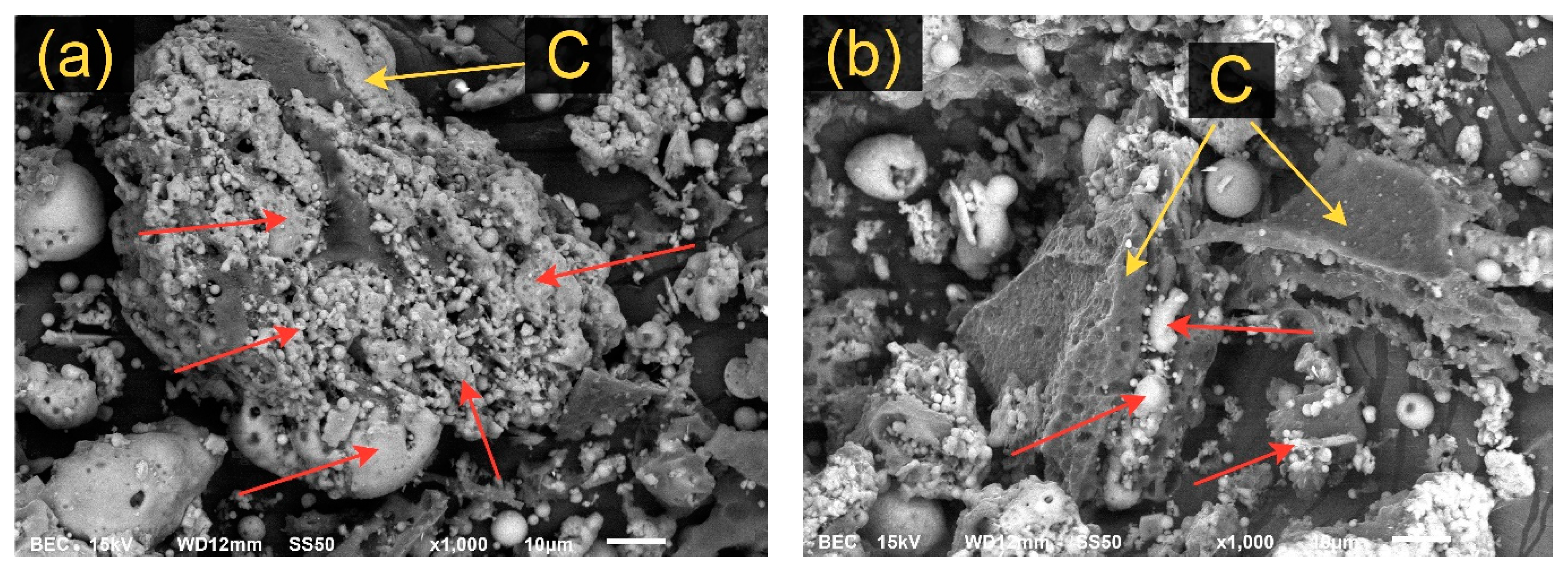
  • The carbon content of the concentrate obtained after flotation using diesel as the collector reaches ~19.8 wt %. Using a particle size of 40–71 µm, a ~99% recovery of unburned carbon can be provided after a 240 s flotation time. The microstructure investigation by SEM showed that unburned carbon particles of 71–100 µm contain a large number of alumosilicates on the carbon surface, and these prevent the complete interaction of diesel with the carbon particles and decrease carbon recovery to 83%.

Author Contributions

Formal analysis: A.A. and A.V.; investigation: D.V., I.K., A.A., and A.V.; methodology: D.V., I.K., and D.J.; project administration: D.V.; writing—review & editing: D.V.

Funding

The present study was funded by the Russian Science Foundation project No. 18-79-00305.

Conflicts of Interest

The authors declare no conflict of interest.

References

  1. Mushtaq, F.; Zahid, M.; Bhatti, I.A.; Nasir, S.; Hussain, T. Possible applications of coal fly ash in wastewater treatment. J. Environ. Manag. 2019, 240, 27–46. [Google Scholar] [CrossRef]
  2. Yang, S.; Lin, L.; Li, S.P.; Li, Q.; Wang, X.T.; Sun, L. Assessment and comparison of three high-aluminum fly ash utilization scenarios in Inner Mongolia, China using an eco-efficiency indicator. Waste Manag. Res. 2017, 35, 515–524. [Google Scholar] [CrossRef] [PubMed]
  3. Liu, D.; Fang, L.; Guo, Y.; Yan, K.; Yao, C.; Cheng, F. Effects of calcium oxide and ferric oxide on the process of alumina extraction of coal fly ash activated by sodium carbonate. Hydrometallurgy 2018, 179, 149–156. [Google Scholar] [CrossRef]
  4. Guo, Y.; Zhao, Z.; Zhao, Q.; Cheng, F. Novel process of alumina extraction from coal fly ash by pre-desilicating—Na2CO3 activation—Acid leaching technique. Hydrometallurgy 2017, 169, 418–425. [Google Scholar] [CrossRef]
  5. Ding, J.; Ma, S.; Shen, S.; Xie, Z.; Zheng, S.; Zhang, Y. Research and industrialization progress of recovering alumina from fly ash: A concise review. Waste Manag. 2017, 60, 375–387. [Google Scholar] [CrossRef] [PubMed]
  6. Guo, Y.; Li, J.; Yan, K.; Cao, L.; Cheng, F. A prospective process for alumina extraction via the co-treatment of coal fly ash and bauxite red mud: Investigation of the process. Hydrometallurgy 2019, 186, 98–104. [Google Scholar] [CrossRef]
  7. Xue, Y.; Yu, W.Z.; Jiang, W.Y.; Wen, L.; You, Z.X.; Lv, X.W. A novel process to extract alumina and prepare Fe-Si alloys from coal fly ash. Fuel Process. Technol. 2019, 185, 151–157. [Google Scholar] [CrossRef]
  8. Li, F.; Guo, Z.; Su, G.; Guo, C.; Sun, G.; Zhu, X. Preparation of SiC from acid-leached coal gangue by carbothermal reduction. Int. J. Appl. Ceram. Technol. 2018, 15, 625–632. [Google Scholar] [CrossRef]
  9. Yin, Y.; Ma, B.; Li, S.; Zhang, B.; Yu, J.; Zhang, Z.; Li, G. Synthesis of Al2O3-SiC composite powders from coal ash in NaCl-KCl molten salts medium. Ceram. Int. 2016, 42, 19225–19230. [Google Scholar] [CrossRef]
  10. Ma, B.; Ren, X.; Yin, Y.; Yuan, L.; Zhang, Z.; Li, Z.; Li, G.; Zhu, Q.; Yu, J. Effects of processing parameters and rare earths additions on preparation of Al2O3-SiC composite powders from coal ash. Ceram. Int. 2017, 43, 11830–11837. [Google Scholar] [CrossRef]
  11. Yan, L.; Wang, Y.; Li, J.; Shen, H.; Zhang, C.; Qu, T. Preparation of polymeric aluminum ferric chloride (PAFC) coagulant from fly ash for the treatment of coal-washing wastewater. Desalin. Water Treat. 2016, 57, 18260–18274. [Google Scholar] [CrossRef]
  12. Li, J.; Li, J.; Liu, X.; Du, Z.; Cheng, F. Effect of silicon content on preparation and coagulation performance of poly-silicic-metal coagulants derived from coal gangue for coking wastewater treatment. Sep. Purif. Technol. 2018, 202, 149–156. [Google Scholar] [CrossRef]
  13. Hu, P.; Hou, X.; Zhang, J.; Li, S.; Wu, H.; Damø, A.J.; Li, H.; Wu, Q.; Xi, X. Distribution and occurrence of lithium in high-alumina-coal fly ash. Int. J. Coal Geol. 2018, 189, 27–34. [Google Scholar] [CrossRef] [Green Version]
  14. Li, S.; Qin, S.; Kang, L.; Liu, J.; Wang, J.; Li, Y. An Efficient Approach for Lithium and Aluminum Recovery from Coal Fly Ash by Pre-Desilication and Intensified Acid Leaching Processes. Metals 2017, 7, 272. [Google Scholar] [CrossRef]
  15. Lanzerstorfer, C. Pre-processing of coal combustion fly ash by classification for enrichment of rare earth elements. Energy Rep. 2018, 4, 660–663. [Google Scholar] [CrossRef]
  16. Wang, Z.; Wang, Z.; Dai, S.; Zou, J.; French, D.; Graham, I.T. Rare earth elements and yttrium in coal ash from the Luzhou power plant in Sichuan, Southwest China: Concentration, characterization and optimized extraction International Journal of Coal Geology Rare earth elements and yttrium in coal ash from the Luz. Int. J. Coal Geol. 2019, 203, 1–14. [Google Scholar] [CrossRef]
  17. Taggart, R.K.; Hower, J.C.; Hsu-Kim, H. Effects of roasting additives and leaching parameters on the extraction of rare earth elements from coal fly ash. Int. J. Coal Geol. 2018, 196, 106–114. [Google Scholar] [CrossRef]
  18. Valeev, D.; Kunilova, I.; Alpatov, A.; Mikhailova, A.; Goldberg, M.; Kondratiev, A. Complex utilisation of ekibastuz brown coal fly ash: Iron & carbon separation and aluminum extraction. J. Clean. Prod. 2019, 218, 192–201. [Google Scholar] [CrossRef]
  19. Cui, L.; Cheng, F.; Zhou, J. Preparation of high purity AlCl3·6H2O crystals from coal mining waste based on iron(III) removal using undiluted ionic liquids. Sep. Purif. Technol. 2016, 167, 45–54. [Google Scholar] [CrossRef]
  20. Lysenko, A.P.; Kondrateva, E.S.; Shilovskiy, S.Y. Electrochemical production of aluminum hydroxide, including the removal of iron from aluminum chloride. Tsvetnye Met. 2018, 5, 41–44. [Google Scholar] [CrossRef]
  21. Han, X.X.; Zhang, T.A.; Lv, G.Z.; Pan, X.J.; Fu, D.X. Effects of additives on alumina preparation from aluminum chloride solution by electrolytic transformation. JOM 2019, 71, 1574–1580. [Google Scholar] [CrossRef]
  22. Hwang, J.Y.; Sun, X.; Li, Z. Unburned Carbon from Fly Ash for Mercury Adsorption: I. Separation and Characterization of Unburned Carbon. J. Miner. Mater. Charact. Eng. 2015, 1, 39–60. [Google Scholar] [CrossRef]
  23. Bartoňová, L. Unburned carbon from coal combustion ash: An overview. Fuel Process. Technol. 2015, 134, 136–158. [Google Scholar] [CrossRef]
  24. Adamov, E.V. Technology of Ores of Non-Ferrous Metals; NUST MISiS: Moscow, Russia, 2007. [Google Scholar]
  25. Vasilyev, A.M.; Kuskov, V.B. Specific features of the concentration process for fine-grained materials in a short-cone hydrocyclone. Obogashchenie Rud 2018, 2, 30–34. [Google Scholar] [CrossRef]
  26. Valentim, B.; Białecka, B.; Gonçalves, P.A.; Guedes, A.; Guimarães, R.; Cruceru, M.; Całus-Moszko, J.; Popescu, L.G.; Predeanu, G.; Santos, A.C. Undifferentiated inorganics in coal fly ash and bottom ash: Calcispheres, magnesiacalcispheres, and magnesiaspheres. Minerals 2018, 8, 140. [Google Scholar] [CrossRef]
  27. Valeev, D.; Mikhailova, A.; Atmadzhidi, A. Kinetics of iron extraction from coal fly ash by hydrochloric acid leaching. Metals 2018, 8, 533. [Google Scholar] [CrossRef]
  28. Yang, L.; Zhu, Z.; Li, D.; Yan, X.; Zhang, H. Effects of particle size on the flotation behavior of coal fly ash. Waste Manag. 2019, 85, 490–497. [Google Scholar] [CrossRef]
  29. Yang, L.; Li, D.; Zhu, Z.; Xu, M.; Yan, X.; Zhang, H. Effect of the intensification of preconditioning on the separation of unburned carbon from coal fly ash. Fuel 2019, 242, 174–183. [Google Scholar] [CrossRef]
  30. Teplov, O.A. Influence of Phase Transitions on the Macrokinetics of the Gaseous Reduction of Iron Oxide. Russ. Metall. 2018, 1, 14–18. [Google Scholar] [CrossRef]
  31. Teplov, O.A.; Korenovskii, N.L.; Lainer, Y.A. Thermogravimetric study of the dehydration and reduction of red mud. Russ. Metall. 2015, 1, 12–18. [Google Scholar] [CrossRef]
  32. Grudinskii, P.I.; Dyubanov, V.G.; Zinoveev, D.V.; Zheleznyi, M.V. Solid-phase reduction and iron grain growth in red mud in the presence of alkali metal salts. Russ. Metall. 2018, 11, 1020–1026. [Google Scholar] [CrossRef]
Figure 1. X-ray diffraction (XRD) patterns of raw CFA from the Omsk TPS-4.
Minerals 09 00320 g001
Figure 2. SEM images of the raw CFA samples from the Omsk TPS-4.
Minerals 09 00320 g002
Figure 3. Flowchart of the dry magnetic separation of the Omsk CFA for the magnetite and alumosilicate concentrates obtained (in all tests, losses of CFA were from 1.4 to 3.3%).
Minerals 09 00320 g003
Figure 4. The effect of the magnetic intensity (T) on the yield of the magnetic fraction, the grade of magnetite, recovery (R), and separation efficiency (E) by wet magnetic separation of the raw CFA.
Minerals 09 00320 g004
Figure 5. XRD patterns of the non-magnetic (a) and magnetic (b) fractions of CFA after wet magnetic separation at 0.11 T.
Minerals 09 00320 g005
Figure 6. SEM images of the magnetite concentrate: (a) sphere with dendritic structures of magnetite, (b) sphere with hexagonal bulk agglomerates of magnetite, (c) sphere with star-like structures of magnetite, and (d) individual submicron pyramidal crystals of magnetite integrated into the star-like structure.
Minerals 09 00320 g006aMinerals 09 00320 g006b
Figure 7. The effect of the collector volume on the yield of carbon concentrate, the grade of carbon, recovery (R), and flotation efficiency (E) for the non-magnetic fraction of the CFA (diesel is the collector, with a particle size 71–100 µm and a flotation duration of 240 s).
Minerals 09 00320 g007
Figure 8. The SEM images of unburned carbon particles obtained by flotation of the CFA non-magnetic fraction (the collector volume is 3 mL); yellow arrows show porous spherical particle; red arrows show non-hollow elongated rectangular particle.
Minerals 09 00320 g008
Figure 9. The effect of particle size and flotation time on the unburned carbon recovery.
Minerals 09 00320 g009
Figure 10. The SEM images of unburned carbon particles obtained by flotation kinetics tests: (a) particle size of 71–100 µm; (b) particle size of 40–71 µm (yellow arrows show unburned carbon particles; red arrows show alumosilicates particles).
Minerals 09 00320 g010
Figure 11. Flowsheet of the CFA enrichment process using wet magnetic separation and flotation (Y—the amount of the magnetite/carbon concentrate relative to the initial mass of the raw CFA, G—grade of magnetite/carbon, R—recovery of magnetite/carbon, E—magnetic separation/flotation efficiency).
Minerals 09 00320 g011
Table 1. Chemical composition (wt %) of raw coal fly ash (CFA) from the Omsk thermal power station No. 4 (TPS-4).
Na2ОMgОAl2О3SiО2K2ОCaОTiО2MnО2Fe3О4
0.620.8426.5861.650.562.850.990.645.27
Table 2. Chemical composition (wt %) of the fraction after dry magnetic separation of the raw CFA *.
Name of FractionNa2ОMgОAl2О3SiО2K2ОCaОTiО2MnО2Fe3О4
Raw CFA0.620.8426.5861.650.562.850.990.645.27
N-M (I)0.530.7026.9462.250.512.731.08-5.26
M (I)0.610.8825.1959.440.492.780.980.379.27
N-M (II)0.580.5828.9263.030.482.801.22-2.39
M (II)0.621.4524.2356.530.494.420.920.8710.48
Alum. Concent. (III)0.600.5728.2563.690.582.811.18-2.32
Mag. Concent. (IV)0.641.3224.6255.360.524.190.990.9811.37
* The average content of carbon in the samples was 2.7–3 wt %.
Table 3. Chemical composition (wt %) of the magnetic and non-magnetic fractions after wet magnetic separation of the raw CFA *.
Magnetic Intensity, TNa2ОMgОAl2О3SiО2K2ОCaОTiО2MnО2Fe3О4Yield (%)
Magnetic Fraction
0.060.491.5924.5055.700.415.110.770.6610.7724.95
0.070.671.6524.1754.390.425.680.601.1711.2425.74
0.080.521.7823.9255.120.335.140.621.0111.5626.26
0.090.381.9224.1854.220.415.360.571.0111.9528.09
0.100.651.8424.2153.920.414.920.481.1212.4429.02
0.110.522.0523.1753.710.465.380.631.3512.7230.32
Non-Magnetic Fraction
0.060.600.6428.2863.550.542.330.63-3.4474.95
0.071.110.6728.2463.290.732.220.54-3.2074.13
0.080.490.5928.9563.130.562.620.62-3.0373.21
0.090.670.6227.3865.040.612.350.63-2.6671.76
0.100.660.7028.2364.460.592.440.58-2.3470.55
0.110.600.6128.0365.140.622.360.61-2.0369.03
* The average content of carbon in the samples were 2.7–3 wt %.
Table 4. The chemical composition (wt %) of the unburned carbon concentrate and non-magnetic fraction after flotation kinetics tests for 40–71 µm particle size of CFA.
Name of FractionCNa2ОMgОAl2О3SiО2K2ОCaОTiО2Fe3О4
Unburned carbon concentrate19.80.530.5920.6852.930.452.500.901.62
Non-magnetic fraction after flotation1.030.560.6028.4363.790.552.280.781.98

