1. Introduction
Most modern concepts for the isolation of radioactive waste, especially high-level waste, are based on the use of a multi-barrier system in which bentonites are one of the most important components of engineered barrier systems (EBS). Currently, the Russian Federation is considering the concept of constructing a deep disposal facility of radioactive waste in crystalline rocks at the Yeniseisky site (Krasnoyarsky region, Russia), which is preceded by the creation of an underground research laboratory with full-scale experiments [
1,
2,
3].
Due to various historical events, in addition to the radioactive waste (RW) storage facilities used in global practice, there are various nuclear and radiation hazardous facilities in the Russian Federation, which are currently included in the Federal Target Program, “Nuclear and Radiation Safety—NRS-2”, and require special monitoring and/or decommissioning procedures. By the decision of the USSR government based on the proposals from scientists and specialists in the second half of the 1950s of the 20th century, geological exploration and research works began to justify and create deep (underground) disposal test sites for of liquid radioactive waste (LRW) for four nuclear industry enterprises: the Siberian Chemical Combine (Seversk, Russia), the Mining and Chemical Combine (Zheleznogorsk, Russia), the Mayak Production Association (Ozersk, Russia), and the Scientific Research Institute of Atomic Reactors (Dimitrovgrad, Russia). Taking into account the volume of processed radioactive waste, the time costs for solidification, and geological conditions, a decision was made to dispose of LRW in deep-lying sand reservoirs, which are located between thick layers of clay rocks that serve as fluid buffers for reliable isolation of waste [
4]. Solidification technology was further introduced into practice later.
Works on the disposal of RW generally complied with IAEA recommendations and were periodically discussed at thematic meetings since the second half of the 1950s [
5,
6]. Similar facilities for the disposal of industrial wastewater from chemical, pharmaceutical, mining, and other industries, as well as low-level radioactive waste, existed in the USA [
7,
8,
9] but were discontinued at the end of the 20th century. At present, such nuclear power facilities in the Russian Federation are classified as “historical RW disposal sites” and, according to the Federal Target Program for Nuclear and Radiation Safety, they are under constant control [
10] and should be decommissioned in the nearest future but cannot be stopped overnight.
One of the LRW disposal sites operates on the territory of the Siberian Chemical Combine, where isolation takes place in deep-lying (350–550 m from the surface) sandy silt reservoirs located between thick clay horizons [
4,
11,
12,
13,
14,
15]. The geological structure in the disposal site has a synclinal structure and is characterized by the absence of tectonic disturbances. LRW is a thermodynamically non-equilibrium weakly alkaline (pH = 8–10.5) and acidic (pH = 3–4) solution with a total salt value of up to 30 g/L; the cationic composition is determined by sodium, ammonium, and alkaline-earth metals, and the anionic composition is determined by nitrate, sulfate, chloride, and bicarbonate. Also, the solutions contain dissolved corrosion products, small amounts of phosphorus-containing compounds, and silicon in the form of orthosilicic acid and fission products; acidic solutions contain acetic acid [
12,
13,
16]. When LRW enters the reservoir, a specific natural technogenic system is formed in which all its constituent components are transformed, including mineral particles, dissolved components, and the composition of the aqueous solution. The results were obtained during the study of reservoir sand rocks and aimed at identifying the features of the geological environment transformations under prolonged term exposure to highly reactive solutions. These results are unique and have no analogs in world practice. This is primarily because similar disposal methods currently operate only in the USA and the Russian Federation; however, there are very few results of geomonitoring of burials in the USA, especially regarding transformations of mineral matter in the open press, and to a greater extent, they relate to general issues.
Before disposal, liquid radioactive waste is prepared in a special way to maintain the stability of solutions and reduce activity. Then, it is isolated (injected) into sand reservoirs through a system of injection cores. In the wellhead space near the injection core (at up to 30 m), all components of the reservoir are dissolved due to radioactive decay. The vast majority of radionuclides are sorbed on the material of reservoir sands in the range of 70–100 m from the injection cores. Samples for this study were selected from observation cores drilled at a distance of 100–120 m, where radioactivity levels were reduced to background values. The study depths were 270–450 m. The presence interval of technogenic solutions was 330–340 m. Thus, this work examines the influence not of radioactive waste itself but of the effect of accompanying (associated) highly reactive solutions on the geological environment of reservoir layers.
Several articles in scientific journals are devoted to monitoring the state of the subsoil in the area of the Siberian Chemical Combine test site, sorption of radionuclides, and issues of microbiology [
17,
18,
19,
20,
21], but only a few works, including publications by the authors of this study [
22], are devoted to changes in the composition of the solid component of reservoir sands. The presented study examines in detail the geological aspects and issues of dia- and technogenesis, which led to the current state of the solid component of LRW reservoir sands. Studies of the sorption parameters of reservoir sands were previously conducted by various authors and published in production reports and in a number of articles [
17,
23,
24]. Micropaleontological studies referred to by the authors of this study were published in the works of a group of scientists from Tomsk [
25,
26]. Modeling of the filtration and capacitance parameters is given in the works of Pozdnyakov et al. [
27,
28].
The purpose of the present study is to identify the features of the transformation of the mineral component of reservoir layers as a result of long-term exposure to highly reactive solutions of varying acidity and alkalinity, which can range from 30 to 40 years. The LRW reservoir rocks are Cretaceous deposits that have experienced geological processes caused by lithification, changes in the composition of pore water, and an increase in the intra-formational pressure, etc., as well as the action of technogenic processes under the influence of highly reactive solutions accompanying LRW. Thus, technogenic processes are superimposed in relation to geological processes, which determines one of the tasks of this study—to identify the signs of manifestation of both geological and technogenic processes, as well as the comparative characterization of their influence on the composition and microstructure of rocks. The obtained research results will allow us to assess the degree of change in the geological environment, which is necessary to predict the consequences of possible emergency situations during the disposal of various RW, including those in vitrified and cemented form. The main objective of this study was to determine the directions of mineral transformation in the reservoir sands of the LRW and to evaluate their significance for the safety assessment of such a disposal procedure.
2. Materials and Methods
Samples for this study were taken from 5 observation cores at 110–180 m from the injection cores, as well as samples from buffer clay horizons underlying and overlying reservoir layers (beds) and same-age rocks outside the radioactive waste isolation site.
Granulometric analysis was conducted using the sedimentation method in the Department of Lithology and Geochemistry of the All-Russian Scientific and Research Institute of Geology and Mineral Resources of the World Ocean (FSBI “VNIIOkeangeologia”).
Quantitative analysis of the content of rock-forming elements in bulk samples was conducted using the X-ray fluorescence spectral method according to method № 439-PC NSAM VIMS on a sequential spectrometer model Axios mAX and PANalytical in the laboratory of analysis of mineral matter of the IGEM RAS. Additionally, the composition of aqueous extracts was analyzed for all samples.
X-ray diffraction studies were conducted in the N.V. Belov Laboratory of Crystal Chemistry of Minerals (IGEM RAS) using an X-ray diffractometer D/Max-2200 by Rigaku (Tokyo, Japan), as well as at the Department of Engineering and Environmental Geology, Faculty of Geology of Lomonosov Moscow State University (MSU), using an Ultima-IV X-ray diffractometer (Rigaku, Tokyo, Japan) purchased at the expense of the Moscow State University Development Program. Diagnostics of the mineral composition of bulk samples and samples of isolated clay fractions was conducted using the method of comparison of experimental and reference X-ray diffraction patterns. Quantitative mineral analysis was conducted through the full-profile processing of X-ray patterns from non-oriented preparations using the Rietveld method [
29]. Oriented specimens were prepared from clay fraction samples and studied in an air-dried state and after saturation with ethylene glycol vapor in a desiccator for 24 h [
30]. The identification of mixed-layer clay minerals is most accurately performed through the simultaneous analysis of XRD patterns of oriented specimens in different states, e.g., air-dried and ethylene glycol-saturated. Comparison of calculated theoretical XRD patterns and experimentally obtained ones makes it possible to accurately diagnose the composition of mixed-layer minerals, the proportion of different layers, and the ordering parameters (i.e., Reichweite). In particular, modeling is relevant to identifying the structural features of mixed-layer illite–smectite minerals. The Sybilla program, kindly provided by Sevron for academic research was used in this study.
Experimental studies of the sensitivity of the X-ray diffraction method to low-smectite values in sandstones have shown that it is possible to reliably “see” and calculate the amount of smectite only when its content in the rock is above 2%. During the experiments, artificial mixtures of quartz and individual clay minerals (kaolinite, illite, and smectite) were prepared. Clay mineral concentrations were as follows: 0.2%, 0.5%, 1%, 1.5%, 2%, 3%, and 5%. It was found that, in the case of artificial quartz–illite and quartz–kaolinite mixtures, the lower sensitivity threshold for X-ray diffraction analysis is 0.5%. In these cases, the concentrations of illite and kaolinite can be calculated with high accuracy, which was less than 0.5%. For smectite (montmorillonite), a similar threshold was 2%. Only at a content of 2% or more can smectite concentrations be calculated with an accuracy of 0.5% [
31]. When the smectite value is less than 2%, practically no diffraction lines are recorded on the diffraction pattern and, as a result, it is not possible to calculate the amount of smectite in the mixture. Thus, based on the experimental work described above, the actual smectite value in those samples in which they could not be calculated may be 2%–3%. The presence of the smectite component can be judged most correctly only after examination of the clay fraction where its content will obviously be higher than the sensitivity of the X-ray diffraction method.
The study of micromorphology was conducted using scanning electron microscopy (SEM) on a LEOSupra 50 VP (Carl Zeiss, Jena, Germany) at the Faculty of Materials Sciences of Lomonosov Moscow State University. SEM is equipped with a field emission cathode. Studies were conducted in the secondary electron detecting mode at an accelerating voltage of 20 kV and a diaphragm of 60 μm. The samples were attached to the holder using conductive carbon tape. To ensure charge drainage from the samples during the research, their surface was coated with a 10 nm thick layer of chromium on a Q150T Turbo-Pumped Sputter Coater (Quorum Technologies, Laughton, UK) using the magnetron sputtering method.
3. Results
3.1. Geological Position of the Disposal Site and Facies Confinedness
The test site of the Siberian Chemical Combine for the final isolation of LRW is located in the area of sedimentary rocks of the Paleozoic (Carboniferous system), Mesozoic (Triassic, Jurassic, and Cretaceous systems) and Cenozoic (Paleogene, Neogene, and Quaternary systems). The sections of the Cretaceous, Paleogene, and Neogene systems are most fully represented in the works of Rybalchenko et al. [
4]. In the schemes [
4] and other later works (for example [
32]), a practically unmodified geological profile was used through a polygon along the north–south line, which reflects a complex picture of layered sedimentary strata pinching out of horizons and their lack of consistency along the lateral (
Figure 1 and
Figure 2). First, such features of the lithological composition of sediments are determined by the conditions of their formation and paleogeographical conditions in the sedimentation basins during the Cretaceous and Paleogene periods. Studying the conditions of formation and transformation of rocks during geological history is necessary to highlight the role of superimposed technogenic processes. Sandy and silty sandy rocks of Upper Cretaceous LRW are interbedded with clayey and silty clayey deposits. The length and thickness of clay horizons vary; in places, they can wedge out or become sandy, as suggested by a number of authors [
4,
9,
32]. Clays and clay silts of the Upper Cretaceous and Paleogene serve as upper and lower buffer horizons for LRW reservoir sands.
Based on the data available in the literature for geological sections of the depth range of interest to us, a cross-section correlation was conducted according to lithological and micropaleontological features in the depth range of 270–385 m [
25,
26,
33,
34,
35]. The sequence is correlated with their relative geographical position and is shown from west to east; core E-145 is located much further north than the other cores (
Figure 2).
In the studied range of sedimentary formations at the site, three lithological units can be distinguished (from bottom to top):
I—Coniacian (Turonian)—clays and silts with interlayers of sand, plant detritus, and clay fragments underlying in relation to LRW reservoir beds; studied thickness—20–25 m;
II—Santonian—layered sands (IIa) with thin unconsolidated clay layers, horizons with clay pellets and layers enriched in plant detritus—collectors of LRW; thickness varies from 20 to 50 m;
III—Campanian—layered sands (IIb) with thin layers of clays, plant detritus, and sand layers with cross-bedding—are overlying rocks in relation to LRW reservoirs; studied thickness—20–25 m.
The upper overlying clay strata were not included in this study.
The analysis of lithological features allows us to conclude that the formation of layered clays of unit I (K2k(t)) occurred under unstable conditions with frequently changing parameters of the aquatic environment, paleorelief, and in the conditions of a relatively shallow marine basin, which was periodically drained and refilled. During the relative shallowing of the basin, horizons were formed enriched in sandy and silty materials with remains of plant detritus. During transgressions (probably insignificant) and/or in the case of frequent sea level fluctuations in a shallow quiet-water basin, sandy horizons with clay fragments (pellets) were formed. Clay pellets were captured from sediments of the same or similar age exposed on the surface or underwater. These sediments were eroded and delivered in the form of pellets, along with more clay or sandy material into a shallow basin, where they were quickly covered by later sediments and retained their shape. Compared to the overlying sediments studied, the layered clays are characterized by a more distinct consistency of lithological differences. Similar clay deposits could have formed, for example, on the hemipelagic shelf slope.
Sediments of unit II (K2st) accumulated in a flat and probably longshore environment with unstable sea levels and periodic flooding. Marine settings may have transitioned to continental ones in the form of deposits of lagoons or brackish-water lakes disconnected from the sea. Micropaleontological studies indicate the deposition of these sediments in coastal marine environments. At the same time, there are rather thick horizons in which no microfaunal remains were found (e.g., horizon 303–320 m, in core ZN-4), while in other wells at the same level only single shells were found. It can be assumed that, at that time, there were continental conditions and a shallow salty lake-type basin, but it was disconnected from the sea. Then the high lateral variability and rare faunal finds become clear.
Unit III sand deposits (K2cp) with interbedded sands with gradational and cross-bedding were deposited in the coastal zone of a shallow sea with unstable hydrodynamics. Sediments with clay pellets and rare clay interlayers were deposited in a relatively quieter part of the coastal zone. Layered sands with gradational layering were deposited in areas with more active hydrodynamics. The absence of coarse-grained material (or its content in small quantities) indicates a low lifting force of the flow and a relatively low speed. In general, the basin depth in the study area was greater in Campanian times than in Santonian times.
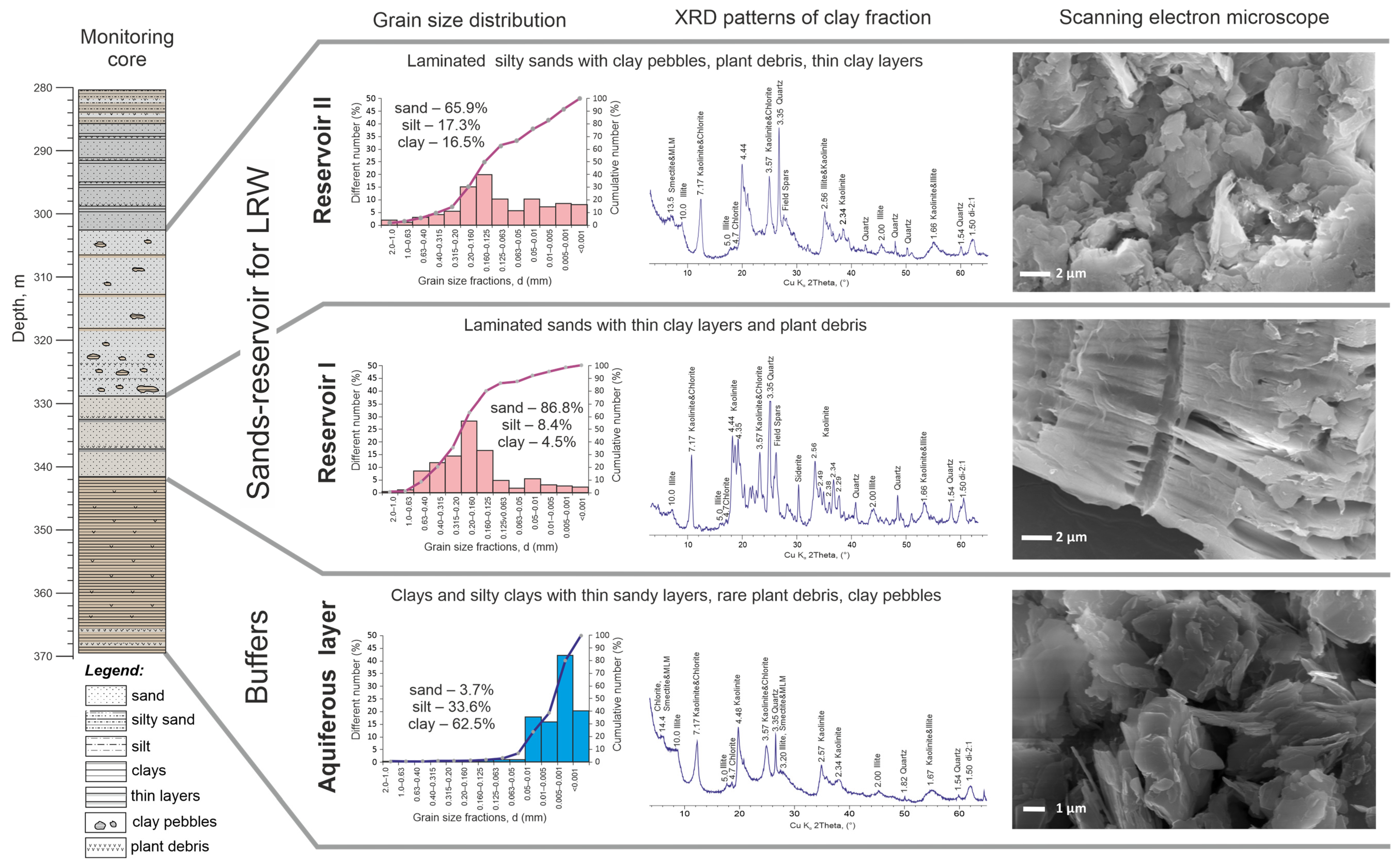
3.2. Grain Size Composition of Sediments
According to the grain size composition, the studied rocks of reservoirs, buffer horizons, and surrounding rocks are divided into three types:
In general, reservoir sands are characterized by heterogeneity in composition and grain size parameters.
Two horizons are distinguished in the thickness of the reservoir sands, which differ in the distribution of granulometric fractions (from bottom to top):
I—Layered sands of Campanian age (unit 1) and relatively homogeneous sands of Santonian age in the upper part of unit 2 are characterized mainly by a monomodal distribution with a mode in thin sands and a convex S-shaped cumulative curve, which reflects the flow genesis of coastal marine sands (
Figure 4).
II—Heterogeneous sands with clay fragments of the 2nd unite are characterized mainly by polymodal distribution and uneven cumulative curves close to the equation y = kx + b, but with numerous small bends. Deposits of moraines, glacial marine, deluvial environments, and soils have similar characteristics [
35,
36].
The deposits of core E-145 outside the test site of the Siberian Chemical Combine are characterized by a significant increase in the silt clay component while maintaining the general type and shape of histograms and cumulative curves (
Figure 4). Similar features of the granulometric composition of core E-145 confirm its relatively more seaward position, which is in good agreement with the lithological data described above.
3.3. Mineral Composition of Reservoir Sands, Buffer Horizons and Outside Rocks
Reservoir sands are polymineral mixtures consisting of quartz, feldspars, and small amounts of carbonates. The identification of mineral composition and typical X-ray diffraction patterns are shown in
Figure 5. The content of clay minerals varies in different samples, but in general, remains quite low—about 20%–25%. Sediments outside the LRW test site are characterized by an increased content of clay minerals; their total sum averages 54% due to an increase in the content of illite, kaolinite, and chlorite to some extent.
In reservoir sands, as well as in samples from core E-145 outside the test site, quartz significantly predominates; the content of feldspars (microcline and albite) is about 30%. Carbonate minerals siderite and dolomite are found in trace amounts. Among clay minerals in the bulk samples, the presence of kaolinite and illite (the predominant minerals), as well as chlorite and smectite, which are contained in very small quantities, was noted. At the same time, chlorite concentrations are rather consistent throughout the section, while smectite concentrations are characterized by high fluctuations from 0 to 7% (
Table 1).
Considering the average values of the mineral composition of reservoir sands and buffer horizons, several main patterns can be identified. First, the predicted differences in the amounts of clay and non-clay minerals are noteworthy. Reservoir sands contain significantly higher contents of quartz, feldspars, and carbonates. Kaolinite with an admixture of illite generally predominates among clay minerals, while in samples from the reservoir zone, the content of kaolinite and illite does not exceed 20%–25% in total. In clay horizons, maximum concentrations can reach up to 30%–40%. The content of the main rock-forming components—quartz, feldspars, and clay minerals—is in clear correlation with the granulometric composition data.
The described features of mineral composition indicate unstable sedimentation conditions and an unstable supply of terrigenous material from the drift area to the sedimentation basin as a result of numerous sea level fluctuations, which confirms the conclusions made earlier.
3.4. Microstructure of Reservoir Sands and Host Rock Samples
The study of sedimentary rock microstructure is a necessary component of the work to identify the morphology of individual particles and aggregates, structural and textural features, particle genesis, stages of transformation, assessment of microporosity, and much more. Technogenic processes associated with the LRW disposal are superimposed in relation to geological processes (dia- and catagenesis), as noted above. Therefore, when studying microstructure, samples from horizons of the same age as the reservoirs in the core E-145, which was drilled outside the LRW disposal site, were analyzed first. Technogenic processes are not evident in the rocks exposed by this core. This is the kind of background on which technogenic processes in the reservoir layers of the injection site are superimposed.
Clay minerals can be very sensitive to environmental changes (temperature, salinity, pH-Eh conditions, etc.) and are often used as indicators of various geological and technogenic processes. At the same time, not all clay minerals in the cement of terrigenous rocks are newly formed. An important role in establishing the genesis of clay minerals is played by scanning electron microscopy, which allows us to study the micromorphology of individual particles and ultramicroaggregates of clay particles to assess their influence on the parameters of the pore space and the relationship with the “skeleton” of the rock—grains of quartz and feldspars (
Figure 6).
In the pore space of both reservoir sands and aquifers, kaolinite occurs in the form of large isometric aggregates, while illite can be found in the form of smaller isometric aggregates. The morphology, form of separation, and nature of particle faces (indistinct and with weak contrast in microphotographs) confirm the terrigenous (redeposited) genesis of kaolinite and the overwhelming proportion of illite, which were probably formed due to erosion and redeposition of material of ancient weathering crusts. Minerals of the smectite group are distinguished by the fact that they contain water molecules and hydrated cations in the absorbed complex and are the most sensitive to environmental changes. By their nature, minerals of the smectite group in reservoir layers and aquitardous horizons can have both terrigenous and authigenic genesis, i.e., they could have been formed as a result of post-sedimentation processes and/or superimposed technogenic processes during the exploitation of reservoir layers. The overlying and underlying clay rocks are natural buffers and are enriched in fine crystalline kaolinite with a low degree of structural order, according to XRD analysis and high dispersion. The micromorphology of individual particles has a shape close to hexagonal, but the sizes of aggregates of such particles are quite small (
Figure 6a). As expected, according to the results of the analysis of particle size distribution and mineral composition, the rocks in the studied depth range have undergone significant transformations. On electron micrographs, the boundaries between terrigenous grains and clay cement are almost invisible. The surface of large feldspar particles and even quartz is greatly altered and transformed. As a result of partial dissolution, the surface of the grains becomes shagreen and beneficial conditions are created for the synthesis of new phases, for example, the synthesis of kaolinite or kaolinite–smectite particles (
Figure 6b–e). Replacement processes occur not as solid-phase transitions, but as a result of the dissolution of parent minerals and the synthesis of clay minerals. During the synthesis of clay minerals, individual fragments of the structure can be inherited, that is, a kind of relatively rapid “assembly” of new minerals occurs from fragments or clusters of partially dissolved minerals. In the pore space in the immediate vicinity of the “remnants” of feldspar grains, the synthesis of smectite or the transformation of illite–smectites is most active. Morphologically, smectites and illite–smectites can be very similar, and it is quite difficult or even impossible to separate them only by the form of isolation. Newly formed aggregates of smectite particles and mixed-layer minerals on the surface of feldspar and quartz grains can be considered the initial stage of mineral transformation, which will subsequently lead to the replacement of the structure of terrigenous grains with clay matter.
In addition to transformations of clay material and the synthesis of new phases, other quite large-scale transformations of the mineral matter of sedimentary rocks occur during catagenesis. Pore water can lead to the development of cracks and further destruction of grains while acting on them (
Figure 6g). The development of fracturing, not only between individual grains and aggregates but also between the grains themselves, potentially leads to an increase in porosity and permeability. However, it is difficult to say to what extent the development of grain fracturing will lead to an increase in secondary permeability because such grains will be more actively subject to transformation processes, which means new clay minerals will be synthesized in the pore space leading to a decrease in permeability.
New mineral phases, such as pyrite and opal, can develop along cracks in terrigenous grains. Pyrite has the form of regular cubic crystals; opal forms round aggregates with thin particles, which in turn, form large accumulations in the pore space (
Figure 6h,i). Thin films between opal aggregates are most likely expressed as organomineral films and thin ultramicroaggregates of smectites. The identification of the mineral composition in all cases was confirmed through semi-quantitative precision chemical analysis using an EDX attachment.
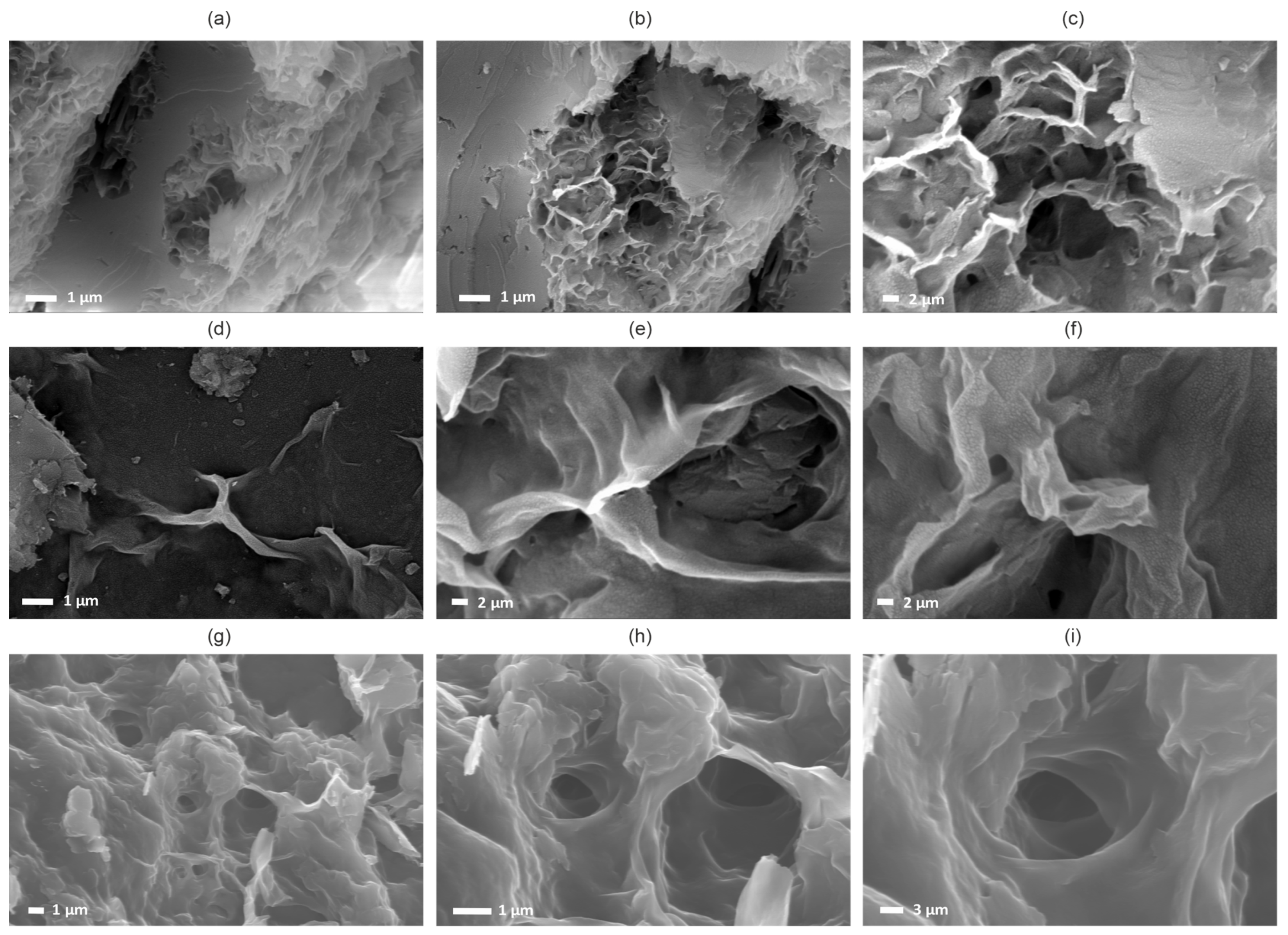
Highly reactive solutions accompanying LRW can significantly influence the course and development of transformation processes. Because these solutions contain a different cationic and anionic composition compared to pore waters, have an increased temperature, etc., it is expected that they will influence the microstructure of sediments differently (
Figure 7). Smectite microaggregates are characterized by specific forms of release, which are often described for hydrothermal processes, for example, in the study of hydrothermal clays of the Kamchatka Peninsula [
37]. The forms of isolation are shown in more detail in
Figure 7, where the changes can be traced from the primary stage of microaggregate nucleation to the formation of a tunnel microstructure (
Figure 7d–i). At the same time, the rock transformations are even more pronounced compared to the rocks of the core E-145. Large grains are destroyed and fragmented, and individual microaggregates are bound together by organomineral films and newly formed smectite phases.
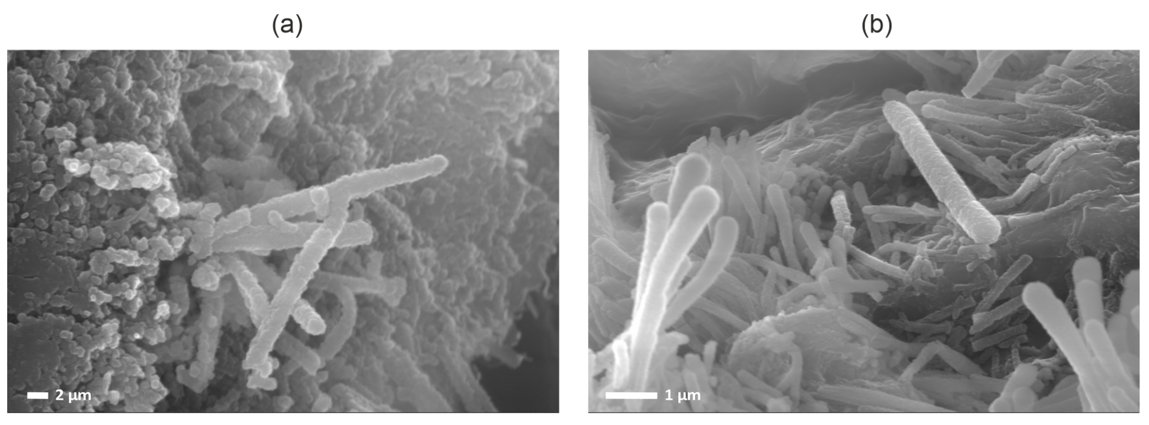
Remnants of microbial communities were also recorded in the reservoir rocks (
Figure 8). Among the transformations in reservoir rocks, the active development of microbial communities, which were previously studied by other researchers, should be noted [
38,
39]. The decomposition products of nitric and organic acids and phosphorus entering the formation along with LRW could serve as a nutrient medium for the active growth of microbial communities. Microbial leaching can make a significant contribution to changes in the composition and properties of rocks.
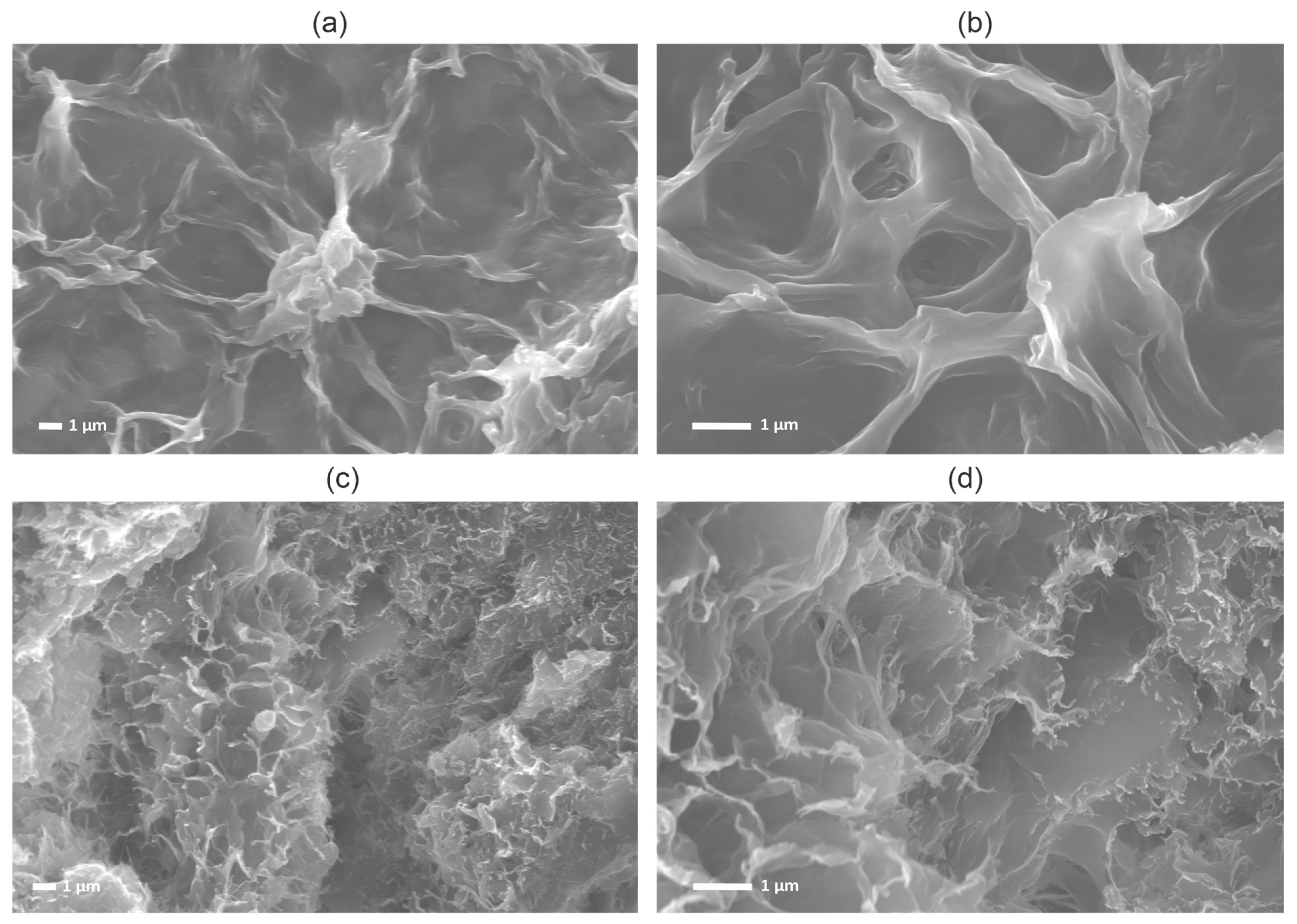
Microstructural studies have revealed the main indicator features of smectites of different origins (
Figure 9). Smectites formed during catagenesis, as a rule, fill the pore space and tightly surround terrigenous grains, can be distinguished by very small aggregate sizes, and have a pseudoglobular microstructure. Smectites formed as a result of the influence of highly reactive solutions on the reservoir are distinguished by rather large aggregates without visible boundaries of individual particles and a coagulated cellular microstructure [
40]. Such smectites are formed in the free space of large pores, which are formed during the partial dissolution of a number of components (sometimes filling it entirely) and are characterized by a loose structure and the absence of a tight fit to terrigenous grains.
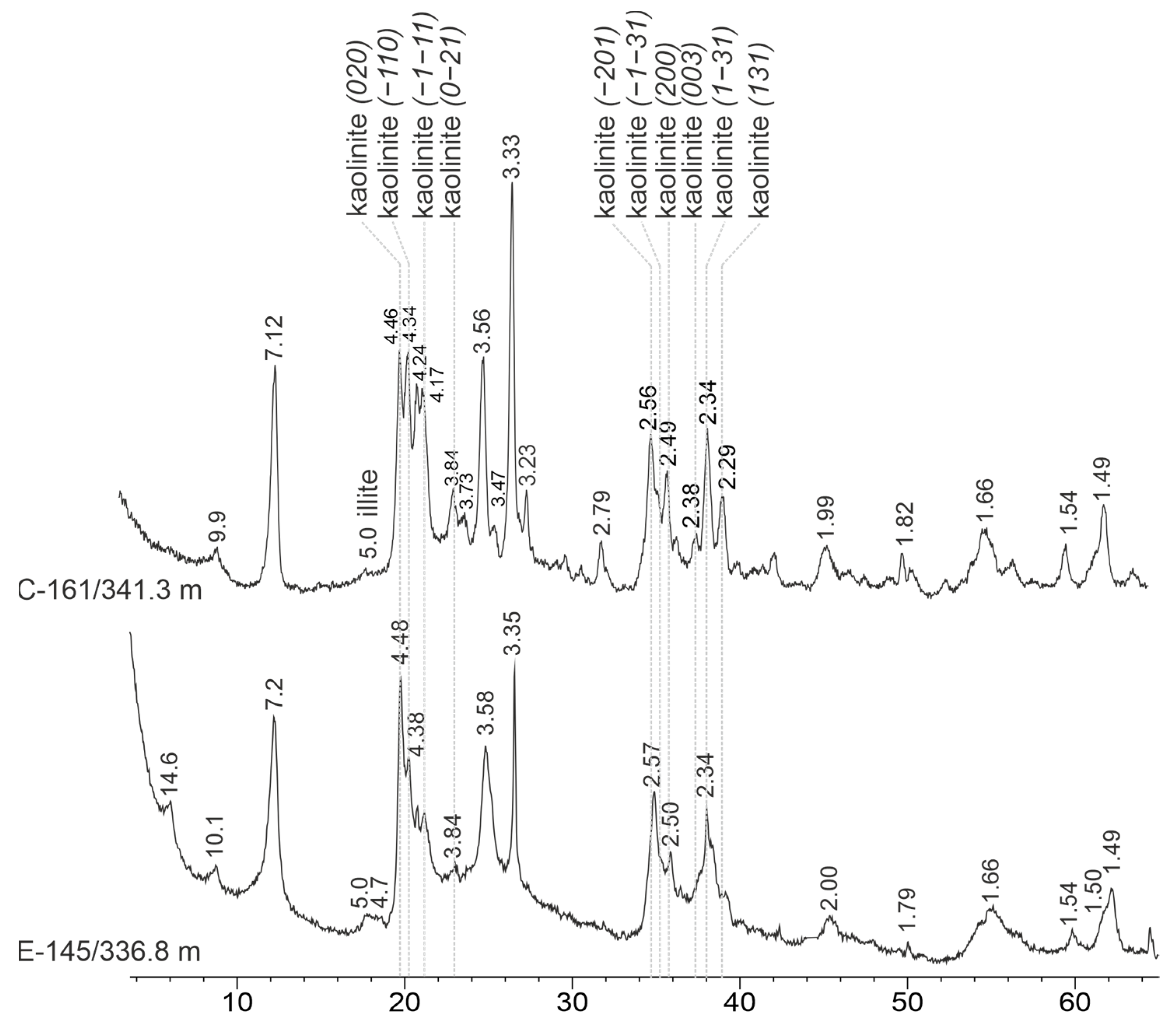
3.5. Features of the Composition of Clay Minerals in the Studied Sediments
The main associations of clay minerals in the studied sediments are smectite–illite–kaolinite and smectite–kaolinite–illite, which differ in the ratio of components, the degree of kaolinite defectiveness, and the presence of various types of mixed-layer clay minerals Among mixed-layer clay minerals in the studied samples, the most common are illite–smectites with a predominance of smectite interlayers, which was confirmed by calculations in the Sibylla program.
Varying degrees of structural order are manifested by the behavior of non-basal reflections in diffraction patterns from non-oriented preparations in the region of angles 19–24° 2Θ and 35–39° 2Θ. With an increase in the degree of structural order (or the decrease in the degree of structural defects), the resolution of closely located non-basal reflexes improves [
41,
42,
43].
Figure 10 shows X-ray diffraction patterns of samples that can be used to describe kaolinite from reservoir sands as ordered and coarse crystalline (sample from core C-161) and kaolinite from same-age deposits outside the test site (sample from core E-145) as disordered and fine crystalline.
Well-sorted reservoir sands are characterized by a high content of illite and mixed-layer minerals of the illite–smectite series, with a predominance of illite interlayers and presence of smectite. A distinctive feature of well-sorted sands is the predominance of kaolinites with a relatively high degree of order among the kaolinite group minerals. Typical X-ray diffraction patterns are shown in
Figure 11.
Poorly sorted silty sand reservoirs are characterized by a higher content of kaolinite group minerals, among which there are kaolinites with a low degree of structural order and kaolinite–smectite mixed-layer clay minerals with a predominance of kaolinite layers, as well as an increase in the proportion of smectite minerals (
Figure 11(II)). Clay deposits of water-retaining horizons are characterized by an increase in the proportion of smectite and poorly ordered kaolinite (
Figure 11(III)). Rocks of the same age as the reservoir layers outside the test site (core E-145) have a siltier composition, as mentioned above, and are characterized by a significant increase in the proportion of smectite and mixed-layer clay minerals in the clay fraction (
Figure 11(IV)).
Thus, it was revealed that well-sorted sands are characterized by a predominance of well-ordered kaolinite with relatively large particles, while poorly sorted sands are characterized by poorly ordered and fine crystalline kaolinites with an increasing proportion of smectite and mixed-layer minerals. Rocks outside the injection site (E-145) are characterized by an increased proportion of swelling minerals in the clay fraction. There is also an increase in the proportion of smectite and mixed-layer minerals in horizons with clay pellets. A summary of the differences in the composition of studied rock types is shown in
Figure 12.
3.6. Structure of Smectites in Reservoir Sands and Background Sediments
Smectites from reservoir beds are represented by rather thin sheet-like particles with the appearance of curved edges. High-resolution transmission electron microscopy images of the thin edge of a single particle were obtained with stripes of crystalline grid layers corresponding to the basal planes. The images obtained this way at the level of the crystal structure (
Figure 13) allow us to calculate interplanar distances that correspond to the values d
001 ~10 Å, 10.8–11.2 Å and 14.5–14.7 Å and can be correlated with smectites in different degrees of dehydration and different interlayer compositions. It was noted that layers with d
001 = 9.9–10.0 Å form packs of 2–4 layers, while layers with d
001 = 14.5–14.7 Å are single and represent small fragments. Similar results were previously published by the authors [
22]. In addition to such particles, numerous relatively large ultramicroaggregates of several particles almost without curved edges for which it was impossible to obtain inverse grid stripes have also been described. Such smectite formations appear in X-ray diffraction patterns in the form of unclear deviations from the background in the region of small angles, which acquire relatively clear reflections after saturation with ethylene glycol.
Smectite particles from same-age sediments as the reservoir deposits outside the injection area are represented by irregularly shaped aggregates (2–3 µm in size) consisting of nanoparticles (with a coherent scattering region size along the C axis of 20–60 nm) randomly oriented in the (001) plane for which microdiffraction patterns with hk
0 ring reflexes were obtained (
Figure 13b). The aggregates are predominantly thin with contrast showing at the boundaries of nanoparticles; thicker aggregates are less common. In general, smectite particles from same-age sediments are thinner and finer and can be characterized by a much greater distribution of curved edges.
According to energy dispersive analysis with similar cation compositions in smectite layers from the test site and beyond, significant variations in the content of interlayer cations are observed with a fairly similar composition of octahedral and tetrahedral cations. The average composition of smectites from reservoir beds is (Al1.41Fe0.51)(Si3.91Al0.09). The average composition of smectites outside of technogenic influence can be written as follows: (K0.07Mg0.14)(Al1.54Fe0.40)(Si3.82Al0.18). Thus, it is clearly visible that the main differences of technogenic smectite are an increase in the content of octahedral iron, a decrease in tetrahedral silicon, and a deficiency to the complete absence of interlayer cations.
Modeling of X-ray diffraction patterns from oriented preparations revealed that 70% of smectite packets belong to the 2W modification (containing two layers of water in the interlayer space) with an average package thickness of about 14.5 Å, 8% of packages belong to 1W smectite with an average package thickness of 12.5 Å and 22% of the packages are in the 0W (dehydrated) modification with an average package thickness of 10.5 Å [
22]. On the other hand, the results of modeling smectites from same-age deposits revealed the presence of a large amount of mixed-layer illite–smectite clay minerals with a content of illite interlayers of up to 10%–30%, which was not observed in smectites of reservoir beds and is confirmed by energy dispersive analysis data.
The different thicknesses of the packages are associated both with different degrees of hydration of the smectite interlayer and the nature of the interlayer hydrated cations. Type 2W smectite can be more associated with divalent cations (Ca, Mg, etc.), 1W with monovalent cations (Na, K, etc.), and 0W with undersaturated cations. Thus, smectite formed under the influence of technogenic processes differs not only in microstructure, but also in the structure of the 2:1 layer and the composition of the absorbed complex. The results are given in [
22].
Undersaturation with interlayer cations can occur because of a decrease in the layer charge and probably partial protonation of the interlayer (replacement of interlayer cations with oxonium ions). The so-called H
+ form of smectite created in experiments under the influence of inorganic acids cannot exist for a long time under normal laboratory conditions and, as it has been shown by numerous researchers [
44,
45], the interlayer space can again be filled with cations from the environment. However, detailed studies of smectites that would have been exposed to highly reactive solutions for several years in laboratory conditions have not been conducted. Liquid radioactive waste is accompanied by solutions of inorganic acids (including HNO
3), as well as dissolved cations (Al, Si, Fe) due to corrosion products of the components of pipelines and wells and the decomposition of mineral components in the wellhead zone. The presence of the necessary components for the synthesis of smectite minerals, elevated temperature and acidic environmental conditions determine the formation of smectites of a specific composition in reservoir layers. Such formations can be considered as a long-term experiment that has no analogs in the world.
3.7. Forecast of Changes in the Composition of Reservoir Layers
Studies have shown that the main changes in the composition of reservoir beds occur in the partial dissolution of sand grains and the new formation of swelling clay minerals—mainly smectites. Conventionally called “diagenetic”, smectite is widely manifested only in technogenically unaltered rocks. The pore space of sands and silty sands within the area of alteration contains both “diagenetic” smectite and large aggregates of authigenic newly formed (“technogenic”) smectite, which was formed as a result of exposure to LRW. Visual analysis of SEM images suggests that at least 70% of the smectite in the sands and silty sands of the reservoir that were influenced by LRW is classified as “technogenic”. Considering that the injection of LRW at the test site began in 1963, about 0.7 weight % of “technogenic” smectite was synthesized in the pore space during this time. This small amount of smectite did not affect the permeability of the reservoir; however, taking into account its location in the solution migration channels and the ongoing formation process, “technogenic” smectite can significantly affect the sorption properties of rocks as a whole. The sorption properties of reservoir sands will increase unevenly over time depending on the rate of synthesis of “technogenic” smectite. However, given that, currently, only low- and medium-active waste is disposed of in reservoirs, and high-level waste is subjected to conditioning and solidification, the amount of waste has decreased significantly, and the impact on the geological environment has also decreased. Therefore, the synthesis of new smectite phases will not proceed so intensively, and a visible increase in the smectite content can hardly be expected. However, the formation of even a small number of swelling phases with high sorption characteristics will increase the safety of RW isolation within the storage facility.
3.8. Transformation of the Geological Environment under the Influence of LRW
The following observed facts and conclusions can be summarized in the conclusion of the conducted research.
According to the lithological study of cores and descriptions of sand samples from reservoir beds they can be divided into two horizons (from bottom to top):
Layered sands with thin, unconsolidated clay layers, horizons with clay pellets, and layers enriched in plant detritus, with thickness varying from 20 to 50 m;
Layered sands with thin clays layers and plant detritus and sand layers with cross-bedding; the studied thickness is 20–25 m.
As a result of the correlation and comparison of lithological columns with micropaleontological analysis data, it was revealed that the unit of reservoir sands belongs to the Santonian stage of the Upper Cretaceous and was formed in a shallow, periodically drained basin in conditions close to lagoonal. The unit is overlain by Campanian, deeper-water marine layered sands and is underlain by clayey layered sediments of the Coniacian–Turonian stages that formed in deeper-water conditions than those described above.
Based on lithological studies of the section of core E-145 (depth 200–420 m) selected outside the test site, several stages of the sedimentary basin formation in the area of the LRW disposal site can be identified:
Stage 1—Turonian (420–413 m, greenish-blue silts and clays)—marine sedimentation conditions;
Stage 2—Coniacian (413–371 m, a unit of interlayered sands and clays)—shallow sea conditions with periodic sea level fluctuations;
Stage 3—Santonian (371–331 m, layered sand unit)—the shallowest sediments presented in the section.
The beginning of the stage is characterized by a possible break in sedimentation with rewashing, expressed in a layer with numerous fragments of different composition, predominantly clay. The deposits of this stage are generally characterized by a more homogeneous sandy composition with thin clayey layers in the lower part of the pack and a large number of cross-bedded layers with lignin and carbonaceous matter. The features of the lithology and the presence of cross-bedding make it possible to classify the conditions under which the deposits of this pack were formed as lagoonal:
Stage 4—Campanian (331–280 m, interbedded sand unit, silts, and clays)—sediments of the coastal zone, transitional between lagoonal and shallow sea sediments. It is characterized by periodic flooding manifested in pelitic and silty pelitic layers and the development of landslide processes expressed in the presence of clay fragments;
Stage 5 (280–237 m, layered sand unit)—sediments of the coastal part, but deeper than during the formation of Stage 4;
Stage 6—(237–200 m, layered clay unit)—sediments of a shallow sea, more seaward than the sediments of the underlying unit. The formation of sediments during this stage was uneven, and there were periodic weakly expressed sea level fluctuations manifested in an increase in the content of carbonaceous matter in the clays and then the deposition of sandy sediments.
The granulometric composition of reservoir sands is characterized by high heterogeneity and variations across the section and the area, which was expected based on the results of the analysis of lithological features. In general terms, we can conditionally distinguish two horizons:
I—Layered sands of Campanian age (unit 1) and relatively homogeneous sands of Santonian age (unit 2). The sands are characterized by predominantly monomodal distributions with a thin sand mode and a convex S-shaped cumulative curve, which reflects the flow genesis of coastal marine sands.
II—Actually heterogeneous sands with clay fragments of the pack (2). Sands have predominantly multimodal distributions, often without identifying one mode; the cumulative curves are uneven, overestimated, and close to a straight line but with numerous small bends.
The deposits of moraines, glaciomarine, and deluvial environments and soils have similar characteristics, that is, deposits in the formation of which the influence of the substrate has a stronger effect on the distribution of granulometric fractions than transportation conditions and the hydrodynamic situation is extremely unstable.
The sediments discovered by the so-called “background” core E-145 outside the LRW injection site are distinguished by a silty composition while maintaining the general type and shape of histograms and cumulative curves. Similar features of the granulometric composition of samples from core E-145 confirm its relatively more seaward position which is in good agreement with the lithological parameters.
In terms of mineral composition, reservoir sands are polymineral mixtures consisting of quartz, feldspars, and a small number of carbonates. The content of clay minerals varies in different samples but, in general, remains quite low—about 20%–25%. Kaolinite and illite predominate among clay minerals; the content of chlorite and smectite is not high and rarely exceeds 5%. Sediments outside the LRW test site are characterized by a high content of clay minerals. Their total amounts to an average of 54% due to an increase in the amount of illite, kaolinite, and chlorite (to some extent).
A detailed study of finely dispersed fractions identified the following mineral varieties among clay minerals: kaolinite of varying degrees of structural perfection, illite, a mixed-layer clay mineral of the illite–smectite series with a low amount of swelling (smectite) interlayers (MLM I-S, I > S, I~80%), a mixed-layer clay mineral of the illite–smectite series with a high number of swelling (smectite) interlayers (MLM I-S, S ≥ I), chlorite, and a mixed-layer clay mineral of the chlorite–smectite series with a low number of swelling (smectite) layers (MLM Ch-S, Ch~80%–90%). The described associations of clay minerals make it possible to compare the horizons with each other.
The composition of clay minerals in the reservoir sands from different cores differs from each other primarily in the number of swelling phases. However, it is possible with a high degree of confidence to distinguish two horizons:
The lower part of reservoir sands is characterized by a significant decrease in the value of swelling phases;
The upper part of the reservoir sands is characterized by a relatively high value of smectite and MLM I-S; kaolinite is usually characterized by a low degree of structural order.
The division into the upper and lower parts of reservoirs is conducted conditionally and, as a rule, is associated with the amount of clay debris. It was also observed that the number of swelling phases increases in horizons with a significant increase in the amount of clay debris. This feature is most clearly manifested in the example of the so-called basal horizons where the number of fragments, according to the lithological description, can be up to 70%–80% of the total volume of the rock. In such horizons, the value of smectite and mixed-layer clay minerals increases. Same-age deposits of the well outside the test site (E-145) retain the same trends and divisions in mineral composition but are characterized by an increase in the proportion of smectite minerals which increases the insulating properties of the surrounding rocks hosting the RW storage facility.
4. Conclusions
The conducted studies have revealed that well-sorted sand-reservoirs are characterized by a predominance of well-ordered kaolinites with relatively large sizes, while poorly sorted sands are characterized by poorly ordered and fine-crystalline kaolinites with an increasing proportion of smectite and mixed-layer minerals. Rocks outside the injection site (E-145) are characterized by an increased proportion of swelling minerals in the clay fraction. There is also an increase in the proportion of smectite and mixed-layer minerals in horizons with clay pellets.
Microstructural changes in sedimentary rocks of buffer horizons and in rocks of the same age as reservoir sands that occur during dia- and catagenesis are manifested in the form of transformation of quartz grains, feldspars, and other terrigenous minerals. The forms of occurrence and morphological features of smectite phases formed as a result of catagenesis under normal geological conditions in the studied rocks have been described. Authigenic non-clay minerals (pyrite and siderite) have been identified, and their morphological features (traits) of manifestation and localization in the pore space have been described.
Microstructural studies allowed us to describe transformation processes in reservoir-sands that lead to changes in the composition and structure of rocks. These processes manifest themselves in the form of the development of leaching zones and their “healing” with newly formed smectite, as well as in the destruction of terrigenous grains, including the development of cracks and growth of newly formed smectite in the pore space of reservoirs. The forms of occurrence and localization of authigenic smectite formed as a result of technogenic impact have also been described. Differences in the morphology of “technogenic” and “syngenetic” smectite are shown additionally in the figures.
A detailed study of smectite particles under a transmission electron microscope has revealed that newly formed smectite phases are characterized by undersaturation or almost complete absence of interlayer cations, which is due to the conditions of their formation and can serve as a diagnostic sign.
It has been shown that the development of the described processes in sand reservoirs can lead to an increase in rock permeability and, as a consequence, to a possible pollution increase by harmful components of LRW. However, in contrast to these processes, there are others that lead to the formation of new smectite phases and transformational reconstitution of kaolinite into kaolinite-smectite mixed-layer clay minerals. Thus, open pores and leaching sites are “healed” by large smectite miroaggregates. All smectite phases are very small in size; as a rule, they fill the pore space in the form of thin microaggregates of complex shape and have good sorption abilities. Even a small content of smectite layers in the structure of kaolinite leads to a significant change in its morphological features and behavior in the pore space, as well as an increase in its sorption rates.
Thus, we can conclude that, despite the obvious impact of highly reactive solutions accompanying LRW, the insulating properties of the geological environment are maintained and possibly improved to some extent. The rocks surrounding the test site serve as an additional natural barrier, which can be characterized by a higher value of smectite phases with good sorption abilities compared to reservoir sands. The same can be said about the overlying and underlying buffer clay horizons, which are characterized by increased values of smectite phases, including in the composition of mixed-layer clay minerals.


