Review

An Overview of Currently Applied Ferrochrome Production Processes and Their Waste Management Practices

by
Stephanus P. du Preez
1,*,
Tristan P. M. van Kaam
2,
Eli Ringdalen
3,
Merete Tangstad
2,
Kazuki Morita
4,
Dmitri G. Bessarabov
1,
Pieter G. van Zyl
5 and
Johan P. Beukes
5
1
Hydrogen South Africa Centre of Competence, Potchefstroom Campus, North-West University (NWU), Potchefstroom 2520, South Africa
2
Department of Material Science and Engineering, Norwegian University of Science and Technology (NTNU), Alfred Getz vei 2, 7034 Trondheim, Norway
3
Sintef Industry, 7465 Trondheim, Norway
4
Department of Materials Engineering, Graduate School of Engineering, The University of Tokyo, Tokyo 113-8656, Japan
5
Chemical Resource Beneficiation (CRB), Faculty of Natural and Agricultural Sciences, Potchefstroom Campus, North-West University (NWU), Private Bag X6001, Potchefstroom 2520, South Africa
*
Author to whom correspondence should be addressed.
Minerals 2023, 13(6), 809; https://doi.org/10.3390/min13060809
Submission received: 3 May 2023 / Revised: 8 June 2023 / Accepted: 9 June 2023 / Published: 13 June 2023

Abstract

:
Ferrochrome (FeCr) is the main source of virgin chromium (Cr) units used in modern-day chromium (Cr) containing alloys. The vast majority of produced Cr is used during the production of stainless steel, which owes its corrosion resistance mainly to the presence of Cr. In turn, stainless steel is mainly produced from Cr-containing scrap metal and FeCr, which is a relatively crude alloy between iron (Fe) and Cr. The production of FeCr is an energy and material-intensive process, and a relatively wide variety of by-products, typically classified as waste materials by the FeCr industry, are created during FeCr production. The type and extent of waste generation are dictated by the smelting route used and the management practices thereof employed by a specific smelter. In some cases, waste management of hazardous and non-hazardous materials may be classified as insufficient. Hazardous materials, such as hexavalent Cr, i.e., Cr(VI), -containing wastes, are only partially mitigated. Additionally, energy-containing wastes, such as carbon monoxide (CO)-rich off-gas, are typically discarded, and energy-invested materials, such as fine oxidative sintered chromite, are either stockpiled or sold as ordinary chromite. In cases where low-value containing wastes are generated, such as rejects from ore beneficiation processes, consistent and efficient processes are either difficult to employ or the return on investment of such processes is not economically viable. More so, the development of less carbon (C)-intensive (e.g., partial replacement of C reductants) and low-temperature pellet curing processes are currently not considered by the South African FeCr smelting industry. The reasoning for this is mainly due to increased operation costs (if improved waste management were to be implemented/higher cost reductants were used) and a lack of research initiatives. These reasons result in the stagnation of technologies. From an environmental point of view, smelting industries are pressured to reduce C emissions. An attractive approach for removing oxygen from the target metal oxides, and the mitigation of gaseous C, is by using hydrogen as a reductant. By doing so, water vapor is the only by-product. It is however expected that stable metal oxides, such as the Cr-oxide present in chromite, will be significantly more resistive to gaseous hydrogen-based reduction when compared to Fe-oxides. In this review, the various processes currently used by the South African FeCr industry are summarized in detail, and the waste materials per process step are identified. The limitations of current waste management regimes and possible alternative routes are discussed where applicable. Various management regimes are identified that could be improved, i.e., by utilizing the energy associated with CO-rich off-gas combustion, employing a low-temperature alternative chromite pelletization process, and considering the potential of hydrogen as a chromite reductant. These identified regimes are discussed in further detail, and alterative processes/approaches to waste management are proposed.

1. Introduction and General Information on Chromite

Approximately 82 different minerals contain chromium (Cr), of which chromite is the only economically viable Cr source being exploited in large volumes [1,2]. The chromite mineral belongs to a spinel mineral group characterized by the formula [(Mg, Fe2+)(Al, Cr, Fe3+)2O4] [3,4]. The heat-, corrosion-, and oxidation-resistance of stainless-steel alloys is due to the presence of chromium (Cr) therein. In general, the higher the Cr content of an alloy, the more heat-, corrosion-, and oxidation-resistant the alloy becomes. Various alloys can contain between 12–35% Cr and are essential in modern-day society. However, beyond a certain Cr addition %, the mechanical strength and abrasion resistance of such an alloy decrease. The vast majority of mined chromite, estimated at approximately 90–95%, is used to produce various ferrochrome (FeCr) grades. Subsequently, the stainless-steel industry consumes 80–90% of produced FeCr. Therefore, chromite and FeCr demands are driven by the demand for stainless steel. In 2013, global stainless-steel production was expected to grow by an average of 5.5% per annum [5,6,7]. In 2021, stainless-steel production increased by 13% when compared to 2020 [8].
Alluvial, podiform, and stratiform deposit types are the commercially exploitable chromite ore sources [9,10,11]. Of these deposit types, stratiform-type chromite deposit ores are mainly exploited due to their large lateral continuity and regular layering [9]. The value of chromite ore is however determined by the Cr2O3 content and the Cr/Fe ratio. The chemical composition of chromite varies significantly from country to country, as summarized in Table 1 [12,13]. The values reported here are post-beneficiation (discussed in Section 3.1).
In this review, chromite originating from South Africa and processes used by the South African FeCr industry are mainly referred to as it is estimated that South Africa holds >70% of the global viable chromite ore reserves [9,10,14,15]. More so, in 2012, chromite originating from South Africa accounted for 41% of globally mined ore. It is estimated that in the same year, 55% of the approximate 10 million tons of chromite mined in South Africa was exported, which suggests that 28% of globally smelted chromite ore originated from South Africa [6,7,13,16]. More recently, Pariser et al. (2018) reported that South Africa accounted for 60% of the global chrome ore (i.e., chromite) output in 2018 [17]. Nevertheless, the growth in the FeCr industry is paralleled by chromite mining. In 2012, South Africa had a combined annual FeCr production capacity of more than five million tons [15,18].
The entire economically viable chromite reserve of South Africa is located in a geological structure in the north of South Africa, referred to as the Bushveld Igneous Complex (BIC) [19]. Figure 1 presents the coverage of BIC and the location of the various FeCr smelters [20].
The BIC complex contains several seams of economic interest, i.e., Lower Group 6 (LG6), Middle Group 1 and 2 (MG1 and MG2), and Upper Group 2 (UG2) [9,11]. The Cr/Fe ratio of each seam differs, i.e., the typical Cr/Fe ratio of the LG6 seam is between 1.5–2, the MG1 and 2 seams have ratios of 1.5–1.8, and the UG2 has a ratio of 1.3–1.4 [9,21,22,23,24].
The UG2 seam is primarily exploited as a source of platinum group metals (PGMs), and PGM circuits are designed to reject chromite to the tailings stream [25]. Subsequent upgrading of these tailings allows for the production of charge-grade FeCr by making use of a variety of technological innovations [9,11,22]. UG2 ore accounts for an appreciable amount of chromite being smelted in SA [11], and in 2018, it accounted for approximately 10% of the total ore output [17].
South African chromites have a relatively low Cr/Fe ratio. For instance, South African chromite contains approximately 0.59–0.62 mol Cr3+ in the octahedral sites, whereas Brazilian, Turkish, and Kazak chromite contains between 0.70–0.77 mol Cr3+. Due to this, octahedral sites of the South African chromite are partially occupied by Al3+, which adversely affects its reducibility. More so, these octahedral sites are also to some extent occupied by Fe3+ (approximately 0.06 mol), further reducing its value [26]. In addition to this, Mg2+ present in the tetrahedral sites contributes to the stability of chromite similar to Al3+ [27]. More so, the presence of Mg2+ had a more significant effect on chromite’s resistance to reduction when compared to Al3+. For instance, (Fe2+, Mg2+)Cr2O4 was more resistant than Fe(Cr3+, Al3+)2O4 [28].

2. FeCr Production

The primary FeCr alloy grades produced include high-carbon, medium-carbon, low-carbon, and charge-grade, as shown in Table 2 [24,29]. Low- and medium-grade carbon FeCr demand has decreased substantially since the development of stainless steel production processes such as vacuum oxygen and argon oxygen decarburization. These decarbonatization processes allow for the removal of C and Si during stainless steel production, with acceptable Cr losses ([30] and references therein). Charge-grade and high-carbon grade FeCr are therefore the mainly produced FeCr types [6,7,31]. Due to being relatively similar, these two FeCr grades are collectively referred to as high-carbon charge-grade FeCr [16]. The following sections present various aspects of FeCr production.

2.1. Chromite Smelting Principles

Chromite’s reduction is highly endothermic and a temperature of approximately 1700 °C is continuously required within the furnace smelting zone [32,33]. More so, to separate the Cr-containing alloy from the slag phase, high operating temperatures are required [34]. Electrical energy is the main energy supply required for smelting [35], and various C sources are used as the reductant, e.g., coke, coal, and charcoal [14,33]. In general, reductants with low ash, phosphorous, and sulfur contents are preferred for FeCr production [22,36]. However, the use of coke as the sole reductant is no longer economically viable in South Africa as it has become difficult to source and expensive [37]. In addition to reductants, fluxes are also used during smelting, e.g., dolomite, quartzite, olivine, bauxite, limestone, and calcite, depending on the operation conditions, furnace type, smelting regime, and the chemical composition of the chromite [14,33].
During chromite smelting, the Fe- and Cr-oxide constituencies of chromite are reduced to their metallic states, i.e., Fe0 and Cr0, which subsequently form the FeCr alloy. However, an appreciable fraction of the Fe and Cr are in their carbide form [14]. Of these oxides, the Fe-oxides are reduced and metalized at temperatures lower than Cr-oxide. A minute quantity of silica (SiO2) is inevitably reduced to SiO(g) and undergoes subsequent metallization, which accounts for the Si-content present in FeCr. The reactions occurring during chromite smelting are given in Reactions 1–5 [33]. All ∆H°298K values presented here, and throughout the manuscript, were calculated using the thermodynamics software package HSC 9.
In the early stages of chromite smelting, Fe2O3 is reduced to FeO:
Fe2O3 + C → 2FeO + CO(g), ∆H°298K = 184.13 kJ/mol  (Reaction 1)
FeO is then reduced to Fe0:
FeO + C → Fe + CO(g), ∆H°298K = 154.51 kJ/mol  (Reaction 2)
Cr2O3 is reduced to Cr0:
Cr2O3 + 3C → 2Cr + 3CO(g), ∆H°298K = 805.73 kJ/mol  (Reaction 3)
Some SiO2 is reduced to SiO(g):
SiO2 + C → SiO(g) + CO(g), ∆H°298K = 697.39 kJ/mol  (Reaction 4)
SiO(g) is further reduced to Si0 according to the exothermic reaction:
SiO(g) + C → Si + CO(g), ∆H°298K = −11.91 kJ/mol  (Reaction 5)
In addition to these reactions, some interaction between the ore and CO(g) occurs as CO(g) permeates upwards through the material bed. Reactions 1–3 are repeated in Reactions 6–8 but show the reaction with CO(g) as the reductant, and CO2(g) as the by-product.
Fe2O3 + CO(g) = 2FeO + CO2(g), ∆H°298K = 11.71 kJ/mol  (Reaction 6)
FeO + CO(g) = Fe + CO2(g), ∆H°298K = −17.91 kJ/mol  (Reaction 7)
Cr2O3 + 3CO(g) = 2Cr + 3CO2(g), ∆H°298K = 288.47 kJ/mol  (Reaction 8)
As can be seen from Reactions 6–8, the ∆H°298K values are lower than for Reactions 1–3. This suggests that the reactions between the Fe- and Cr-oxides and CO(g) will proceed at lower temperatures when compared to solid C. More so, it is known that Fe-oxides are reduced to a greater extent in the upper part of the furnace when compared to Cr-oxides via CO(g) [38,39,40], which coincides with the presented ∆H°298K values shown for Reactions 6–8.

2.2. Furnace Types and Smelting Regimes

The production of FeCr is mainly performed in semi-closed (also referred to as open) and closed submerged arc furnaces (SAFs), and to a lesser extent in closed direct current (DC) furnaces [23,41,42]. Beukes et al. (2017) presented a simplified illustration (Figure 2) to differentiate between semi-closed and closed furnaces (including closed SAFs and DC arc furnaces) [30].
The furnace types presented in Figure 2 have dissimilar off-gas management regimes. For instance, during semi-closed SAF operations, off-gas is combusted above the furnace bed before extraction, whereas closed SAF off-gas, which is rich in CO(g), is extracted without being combusted immediately. This CO-rich off-gas is typically flared on furnace stacks or utilized elsewhere to some extent. Off-gas is discussed in more detail in Section 5.1.
There are four relatively well-defined process combinations employed during chromite smelting [15,23,30]. A short description of each combination is presented within the context of the generalized flow diagram (Figure 3), indicating the most commonly applied process steps [14,20,23,43].
(i)
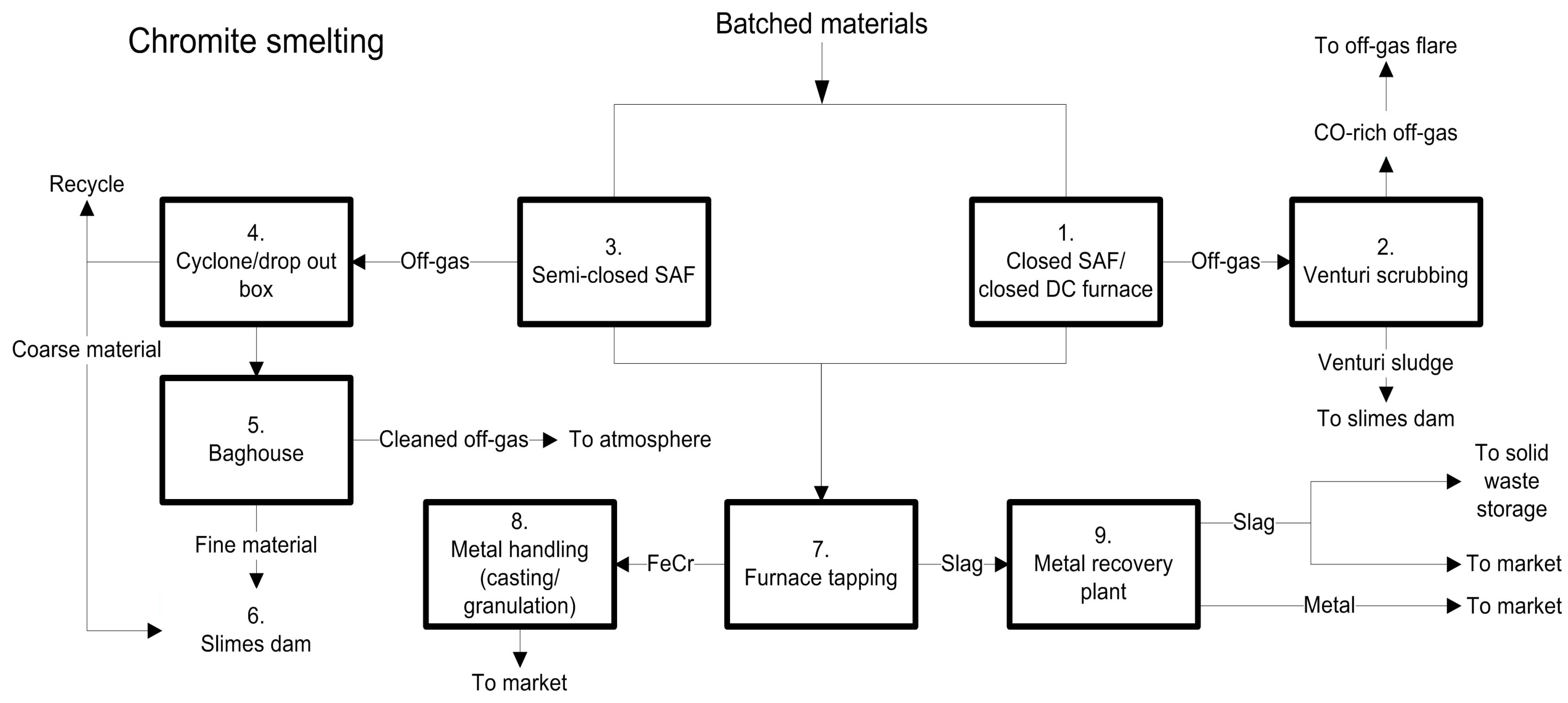
Closed SAFs mainly consume hot pre-reduced chromite pellets (consumed immediately after pre-reduction), coarse (6 mm ≤ typically size ≤ 150 mm) fluxes, and reductants, coupled with wet venturi off-gas scrubbers. This route is commercially referred to as the Premus Process and consists of Process Steps 1–4, 6, and 8–11 in Figure 3. Glencore Alloys apply this process at two smelters [44]. Closed SAFs consuming pre-reduced pelletized feed operate on a basic slag, with a basicity factor (BF) of >1. The BF is defined as [23]:
BF = % CaO + % MgO % SiO 2
Usually, the carbonaceous reductant content present in SAFs during smelting facilitates the burden conductivity. However, due to some of the Fe and Cr already being reduced/metalized, the less carbonaceous reductant is fed to closed SAFs consuming pre-reduced chromite pellets. Thus, the furnace burden lacks conductivity; therefore, a conductive basic slag is used [30,45].
(ii)
Closed SAFs mainly consume oxidized sintered chromite pellets and coarse reductants and fluxes, coupled with venturi off-gas scrubbers. This process route is commercially known as the Outotec process (also applied by Outokumpu at Tornio, Finland). These furnaces are typically operated on an acidic slag (BF < 1) [23], combine Process Steps 2–6 and 8–11, and may or may not include Process Step 7 in Figure 3 [30,46].
(iii)
DC arc furnaces can accommodate exclusively fine materials as a furnace feed. Process Steps include 6, 8, and 9–11, and may or may not include Process Step 7 in Figure 3. Several such furnaces are operational in Kazakhstan and South Africa. DC arc furnaces typically operate on a basic slag regime (BF > 1) [47,48].
(iv)
Conventional semi-closed SAFs mainly consume coarse (also referred to as lumpy) chromite, reductants, and fluxes, coupled with bag filter off-gas treatment. This is the oldest technology applied in South Africa, but it still accounts for a substantial fraction of overall FeCr production (locally and globally) [23,49]. The Process Steps used are 6, 8–10, and 12 in Figure 3 [30,50]. In certain cases, pelletized chromite is also smelted in these furnaces, and Process Steps 1–5 may also be included [30,50]. The majority of South African semi-closed SAFs operate on an acid slag regime (BF < 1). Coarse materials are utilized as they allow process gasses to permeate through the furnace bed [42]. Fine materials (<6 mm) are avoided (or at least limited) as they may facilitate furnace bed sintering, which traps the evolving process gasses and subsequently increases the risk of furnace bed turnovers and eruptions [14,23]. It is however not impossible to smelt a relatively small amount of fines in these SAFs [23]. Operation benefits of semi-closed SAFs include simplicity of operation (i.e., the option to exclude raw material screening), easily accessible electrode equipment and furnace bed (i.e., easier maintenance compared to closed SAFs), and furnace bed visibility (i.e., visually determining process condition). Furthermore, the lack of sophisticated control systems means that less capital is required for FeCr production by semi-closed SAFs. However, these SAFs have lower metallurgical and thermal efficiencies [51].
Table 3 presents the respective Cr recovery (%), the specific energy consumption (SEC), and the economy of scale (EoS) of the four process combinations discussed in the previous paragraphs. Cr recovery refers to the % of Cr recovered from chromite ores (the remaining % Cr is ejected in the slag phase). SEC is defined as the amount of energy (kWh) required to produce 1 ton of FeCr. EoS indicates the maximum size of a furnace concerning energy consumption relevant to the amount of FeCr producible per annum.

3. Processing of Chromite—From Ore to Alloy

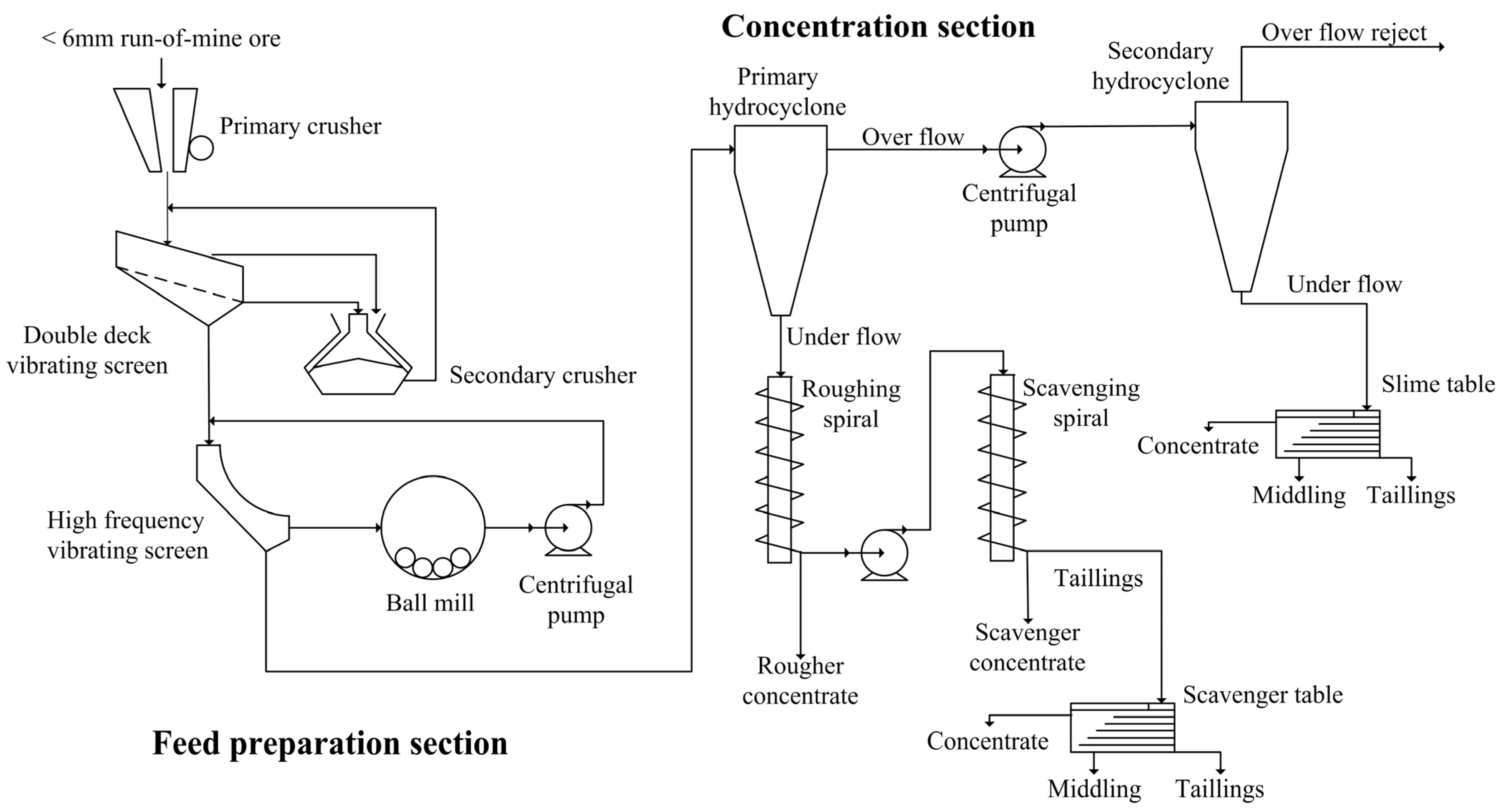
3.1. Chromite Ore Beneficiation

Run-of-mine (ROM) chromite (defined as ore recovered during mining and before further processing) is typically beneficiated before smelting, using a relatively wide variety of processes. Murthy et al. (2011) stated that the most generally used processes are primary and secondary crushing, screening, milling, dense media separation, and gravity separation [10]. The relevant beneficiation steps are however determined by the size of the ROM chromite. South African chromite mines generally recover 10–15% lumpy/coarse ore (15 ≤ typical size range ≤ 150 mm) and 8–12% chip/pebble ore (6 ≤ typical size range ≤ 15 mm), with the <6 mm fraction accounting for the remainder of ore [52]. The beneficiation of lumpy, chips/pebble chromite is achieved by crushing, screening, and dense media separation. The <6 mm fraction is typically milled to <1 mm, followed by upgrading (defined as increasing the Cr2O3 wt%) with hydro cyclones and spiral concentrators to generate chromite of a metallurgical and/or chemical grade [10,30,53].
Figure 4 shows the <1 mm chromite concentrate beneficiation process flow diagram. It is worth noting that the shaking tables (scavenger and slime tables) shown in Figure 4 would likely not be used during large-scale operations and a series of spiral concentrators, operating in parallel, would be employed instead of a single spiral concentrator [30].
The feed preparation section in Figure 4 entails screening the <6 mm fraction from the ROM chromite ores, followed by primary and secondary crushing which is separated by screening. The oversize chromite from the secondary crusher offset is continuously recycled. Through ball-milling, the crushed ore is reduced to a particle size of <1 mm. Hereafter, it is conveyed to the concentration section where the Cr2O3 content of the ore is further upgraded using typical gravity techniques, e.g., spiral concentrators and/or hydro-cyclones [10]. This ore, which has now been upgraded, is referred to as metallurgical-grade ore with a typical Cr2O3 content of ≥45% [52], although lower-grade ores are also often generated.
Milling is the only process step implicated with the formation of environmentally hazardous Cr(VI) [30] if the milling is performed under dry conditions [52,54]. References [52,54] did however employ pulverization, which is an extreme form of milling and is typically not employed by the FeCr industry. Beukes and Guest (2001) reported elevated Cr(VI) levels in samples gathered from a dry-milling circuit at a FeCr producer. As appose to dry milling, wet milling does not generate Cr(VI) [35]. More so, wet milling would be the obvious choice considering that the preceding beneficiation steps (spiral concentrators and hydrocyclones) are wet processes.
Of particular concern is the generation of large quantities of middlings and tailings during beneficiation processes [55,56]. It is estimated that approximately 50% of the total feed material being beneficiated is discarded as tailings, which contain relatively significant quantities of chromite in the ultra-fine size fraction [57]. For instance, beneficiation plants in Sukinda, India, reject large quantities of low- and sub-grade chromite ores (10–38% Cr2O3) to produce a concentrate of approximately 50% Cr2O3 with a yield of 25–35% [58]. In Guleman-Sori, Turkey, an estimated 2.7 million tons of chromite tailings containing approximately 20.7% Cr2O3 have been discarded in the tailings dams of a chromite concentration plant [59]. Therefore, it is typical to have large tailings dams at such beneficiation plants.
Three issues regarding tailing dams have been noted, i.e., groundwater contaminations by seepage, dust emissions by wind-born ultra-fine material distribution, and general environmental impacts (e.g., dam failure, wildlife disruption) [60]. Of particular environmental concern is that the tailings dams may accumulate Cr(VI) throughout their operational lifetime, which can potentially result in environmental and storage concerns [61,62,63].
The generation of Cr(VI) during beneficiation (during the aforementioned dry milling procedures) will likely be minute. Potentially, the water used during chromite beneficiation post-dry milling will likely transfer the water-soluble Cr(VI) from the solid phase to the liquid phase. Considering that such process water is typically recycled for numerous cycles, the build-up of Cr(VI) may occur. If dedicated and efficient Cr(VI) remediation is not implemented, disposal of the solid residues and Cr(VI)-containing process water can result in the accumulation of Cr(VI) within the tailings dam.
From an economic perspective, a certain amount of chromite (which is the value-bearing component) will inevitably be ejected as tailings. A relatively significant amount of work has been conducted on reducing chromite losses in tailings [64,65,66,67,68,69], the beneficiation of low- and sub-grade ores [10,70,71,72], recovering ultra-fine chromite particles [73,74], and the general reprocessing of tailing stockpiles [10,60]. However, beneficiation circuits’ effectiveness depends on the feed quality, and any variations (in physical properties and chemical composition) greatly affect the subsequent recovery of valuable fines [10]. It is therefore relatively difficult to develop effective beneficiation circuits with high and consistent chromite recoveries.
Some work has been carried out on more sophisticated upgrading processes, such as flotation [75]. For instance, a 96.5% chromite recovery from a <100 µm size feed has been achieved under optimal conditions and parameters through column flotation [73]. Flotation is however generally considered as being economically unattractive for the FeCr industry [30] and is typically used in the beneficiation of higher-value products such as PGMs.
In conclusion, considering the inert nature of the solid materials generated during chromite ore beneficiation, there are few concerns regarding the current management thereof other than dust dispersion and the potential of Cr(VI) accumulation in tailings dams. The main issue regarding chromite beneficiation is the volume of material being generated and the potential occurrence of dam failures. Furthermore, the secondary beneficiation of such tailings is complicated by variations in the physical properties thereof and constant operational optimization is required to ensure acceptable chromite recoveries. Tailings beneficiation is further perplexed by economic considerations, as the cost-to-recover is mainly affected by the Cr2O3 content of the recovered chromite and/or FeCr global market values.

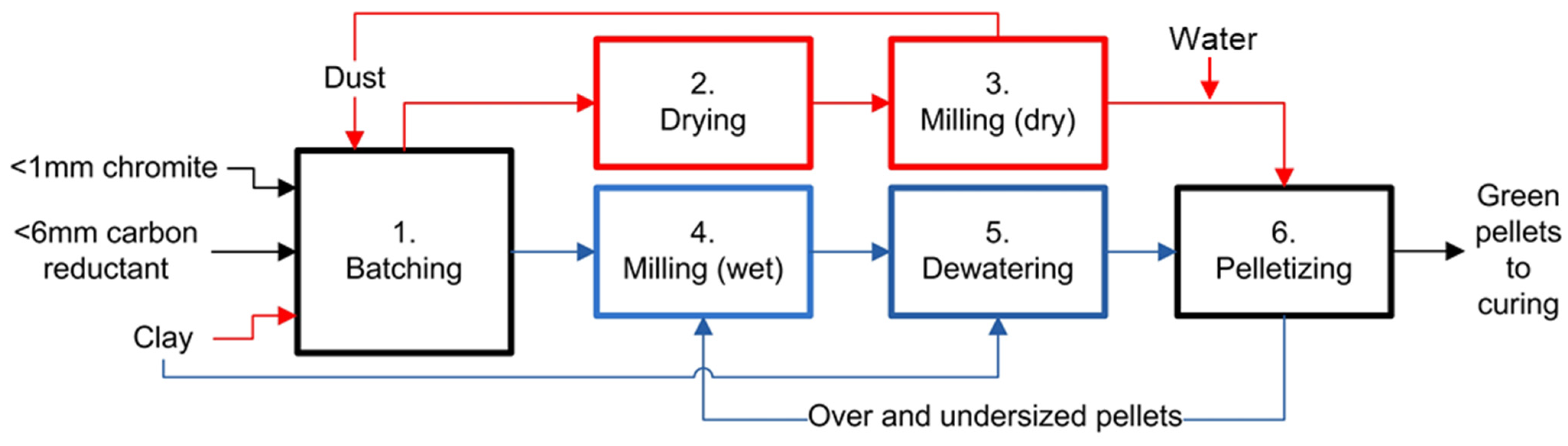
3.2. Green Pellet Generation

Beneficiated ore (as discussed in Section 3.1) is agglomerated to generate green pellets, defined as moist pellets before being cured. Pelletization and briquetting are the most commonly applied agglomeration techniques. Pelletization is the preferred technique as briquetting is conducted using coarser chromite. Chromite briquettes have lower compressive strengths and lower Cr recovery during smelting when compared to sintered/pre-reduced pelletized chromite [14]. Thus, only pelletization processes were considered here.
As indicated in Section 2.2, pre-reduced and oxidative sintered pellets are the two pellet types mainly produced and smelted in closed SAFs. These pellet types and their generation process steps differ from one another. Figure 5 shows a flow diagram of the green pellet generation processes for pellets intended for pre-reduction (indicated in red) or oxidative sintering (indicated in blue) curing processes. Common process steps are indicated in black.

3.2.1. Green Pellet Generation Destined for Pre-Reduction

Green pellets intended for pre-reduction are generated by combining process Steps 1–3 and 6 in Figure 5. Metallurgical grade ore fines or upgraded UG2 ore fines, <6 mm carbon reductant, and a clay binder are batched (weight proportionated) according to a pre-determined metallurgical recipe (Step 1, Figure 5). Green pellets traditionally include 12–14 wt% carbonaceous reductant and 3–4.5 wt% clay, with chromite being the balance. The batched materials are then dried to remove any moisture (Step 2, Figure 5). Dust originating from the drying process is reintroduced into the pellet generation process. The mixture is then ball-milled under dry conditions (Step 3, Figure 5) to generate a homogeneous mixture with a particle size distribution in which 90% of the particles are smaller than 75 µm (d90 ≤ 75 µm) [51]. Dust generated during dry milling is re-introduced into the pellet generation process. To generate green pellets, the mixture is wet agglomerated on pelletizer disks (Step 6, Figure 5). Fine water spray is introduced at various strategic points on the pelletizer disk to enable the pellet formation process.
Raw material spillages do occur during the pellet generation process. These materials are collected and re-introduced to the pelletization process. For pre-reduction, the diameter of green pellets should ideally be between 12–18 mm [51]. Under- and oversized pellets are typically also supplied to closed SAFs.
In summary, wastes generated during green pellet generation intended for pre-reductive curing are relatively limited. Dust formed during material dry milling and material drying is the only material that may be partially classified as a waste material. However, this type of dust consists exclusively of feed materials and is therefore easily recycled.

3.2.2. Green Pellet Generation Destined for Oxidative Sintering

Green pellets intended for oxidative sintering are generated by a combination of Process Steps 1 and 4–6 in Figure 5. This process starts by batching chromite ore fines (<1 mm) and approximately 1–2 wt% <6 mm reductant (Step 1, Figure 5). Though coke is the preferred reductant, materials such as char and anthracite have also been used successfully [51]. Hereafter, the mixture is wet ball milled (Step 4, Figure 5) to generate a homogeneous mixture with a particle size distribution in which 80% of the particles are smaller than 74 µm (d80 ≤ 74 µm) [51]. Moisture is then removed from the wet-milled mixture (Step 5, Figure 5) using ceramic filters. The process water from the dewatering step is reused in the wet milling process. The dewatered material typically contains 8.5 to 9% moisture [51]. Approximately 1% refined clay, such as bentonite, is introduced to the moist mixture and homogenized using a high-intensity mixer. Green pellets are then formed in a pelletization drum (Step 6, Figure 5) [76] and screened to recover pellets with a diameter of 9–13 mm. Under- and oversized pellets are recycled back into the pelletization process, with oversized pellets first being broken down.
Waste generation during green pellet generation destined for oxidative sintering is relatively limited (e.g., material spillages), and no major waste occurs if proper operational conditions are maintained.

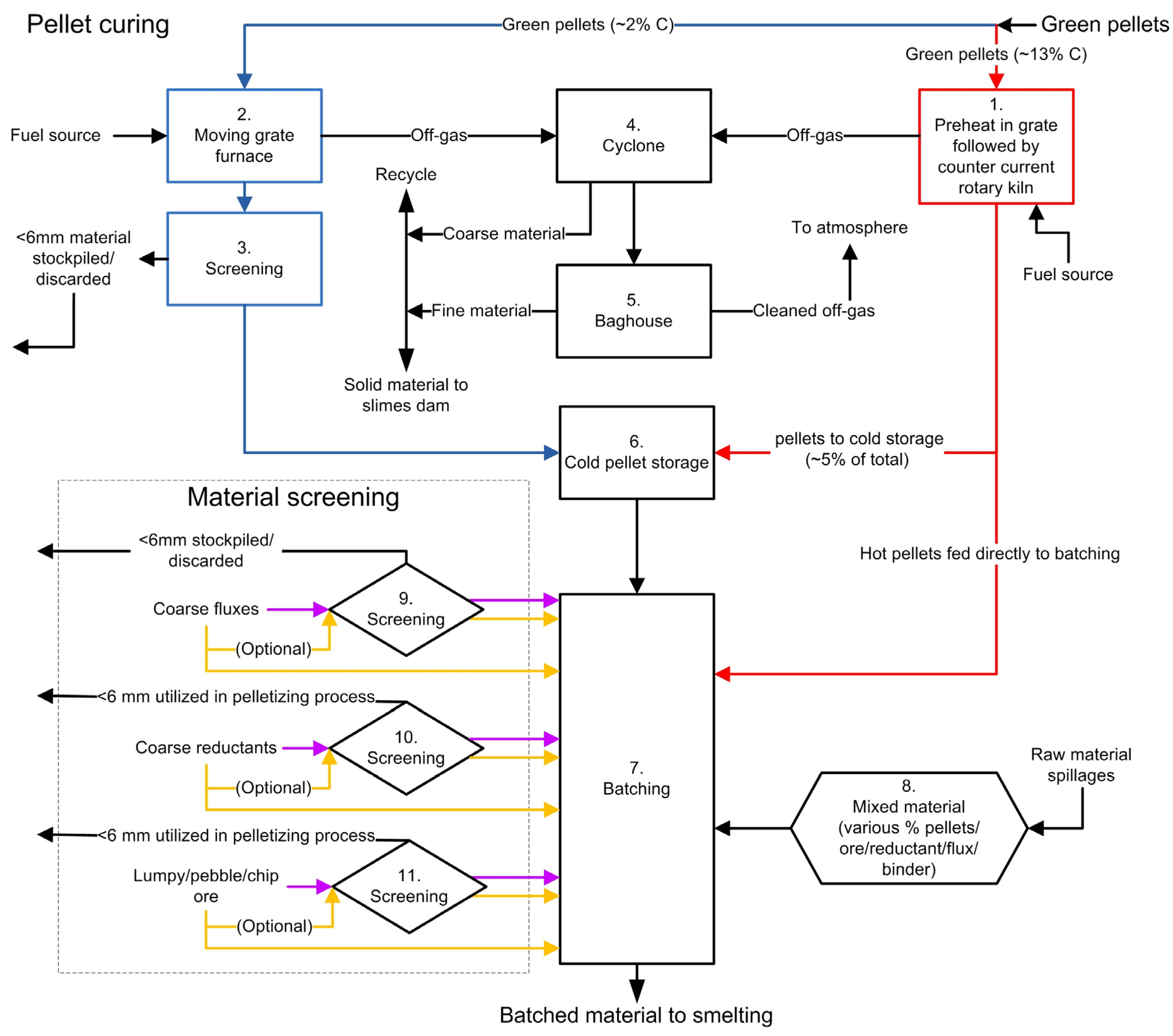
3.3. Pellet Curing and Furnace Feed Material Screening

Here, the green pellet curing processes (pre-reduction and oxidative sintering) are considered as presented in Figure 6. The process steps associated with pre-reduction are indicated in red and those of oxidative sintering are indicated in blue, with commonly shared process steps indicated in black. Raw material screening (shown in the material screening inset) is included as part of Figure 6 as cured pellet screening is usually applied for oxidative sintered pellets fed to closed SAFs. Screening procedures employed for semi-closed and closed furnaces are indicated in yellow and purple, respectively.

3.3.1. Green Pellet Pre-Reduction

Pre-reduction (referred to as solid-state reduction too) is when a fraction of Cr- and Fe-oxides present in the chromite are reduced to lower or zero oxidation states (refer to Reactions 1–3) before being subjected to smelting (typically in a closed SAF).
Pre-reduction consists of Process Steps 1 and 4–7 (Figure 6). The generated green pellets are dried and preheated in a grate before being fired in counter-current rotary kilns (Step 1, Figure 6) with a typical operating temperature of 1300–1400 °C [14,51]. The kiln is mainly heated by combusting crude oil, pulverized coal, or CO-rich off-gas originating from closed SAF operations [14]. Coarse material is removed from the off-gas generated during pellet pre-reduction in the kiln by passing it through a cyclone (Step 4, Figure 6). The coarse material typically consists of carbonaceous reductant and unreacted chromite [23,77,78]. This material is re-introduced into the pellet generation process or discarded (e.g., in a slimes dam). To remove fine particles from the off-gas, it is subsequently passed through a baghouse (Step 5, Figure 6). This specific bag filter dust consists mainly of ash from the combustion pulverized coal (used to heat the kiln) and is usually discarded in a dedicated slimes dam.
The produced pre-reduced pellets are hot-fed directly to closed SAFs without being screened to remove fines [23,44,79]. Approximately 5% of pre-reduced pellets are stored as cold pellets (Step 6, Figure 6) and smelted at a later stage.
The pre-reduced pellets, which are still hot, are conveyed and batched (Step 7, Figure 6) with other furnace feed materials based on a specific metallurgical recipe. This recipe depends on the chemical compositions of the materials to be smelted and the specific furnace slag regime. In some instances, spilled raw materials are included (Step 8, Figure 6), depending on the chemical composition and physical properties thereof.
Wastes generated during the pellet pre-reduction processes are relatively well managed. However, the formation of damrings (material adhering to the kiln interior) is an inevitable occurrence. Figure 7 shows the formation of damrings, and the subsequent text discusses the possible effect on the pre-reduction process.
Figure 7a shows a cross-sectional and longitudinal view of the rotary kiln used during chromite pre-reduction. The presence of damring material can protect the refractory lining of the kiln from direct exposure to high process temperatures, as well as abrasion caused by pellet tumbling. It is also known that the formation of limited damring material at certain strategic areas, indicated with “a” in Figure 7a, can result in an increased pellet retention time within the furnace hot zone, which results in enhanced pre-reduction levels. As opposed to limited damring formation, excessive damring formation, indicated with “b” in Figure 7a, can increase the effective slope that the pellets experience within the furnace. This results in a shorter retention time within the furnace hot zone which reduces the pellet pre-reduction level [80].
Van Staden et al. (2018) stated that the ash of the pulverized fuel used to fire the pre-reduction kiln contributes to the formation of damrings. Approximately 30 wt% Cr2O3 is present in damrings. However, the chromite particles themselves could not contribute to damring formation as the temperature at which chromite softening initiates (i.e., 1756 °C) is significantly higher than the ash softening (i.e., 1054 °C) temperatures [80].
Pre-reduction kilns are typically 60–80 m long to ensure that the pellet retention time during pre-reduction is approximately 3 h. The typically used fuel, i.e., pulverized coal, has a long and penetrating flame, which allows effective heat transfer and a maximized pre-reduction area with a sufficiently high temperature within the kiln. The use of CO-rich off-gas (which is an ash-less fuel) can be used as a pre-reduction fuel but is not completely effective as it has a short flame, limiting effective reduction [81].
Excessive damrings have to be removed intermittently, which is only possible if the entire pre-reduction process is halted. By doing so, the relevant closed SAF is operated on lumpy chromite instead of the pre-reduced pellets, effectively decreasing the metallurgical efficiency of the SAF. In some cases, cold-stored pre-reduced pellets (Step 6, Figure 6) are fed to the relevant closed SAF, which also decreases the metallurgical efficiency when compared to hot-fed pre-reduced pellets [20]. The waste material formed during the process itself is however of little environmental and economic concern.

3.3.2. Green Pellet Oxidative Sintering

Green pellet oxidative sintering entails Process Steps 2–7 (Figure 6). Formed green pellets are introduced to a moving steel belt grate furnace (Step 2, Figure 6). Green pellets are typically placed on top of a layer of pre-sintered pellets to protect the under-laying steel sintering belt from excessive temperatures.
The sintering temperature is gradually increased using gas burners to a sintering temperature between 1400–1500 °C [51]. The pellet C content is subsequently ignited, and ambient air is drawn through the pellet bed. Pellet sintering occurs as the C is combusted, generating a sufficient amount of exothermic energy [11,23,79,82]. Inter-particle binding of chromite grains by molten silicates occurs during sintering to produce mechanically strong pellets [14,83].
Sintered pellets are screened (Step 3, Figure 6) to remove undersized particulate material from the pelletized feed. At some FeCr producers, the undersized particulate material is stockpiled or sold as regular chromite. The suppliers of the sintering technology indicated that the particulate material can be reintroduced into the moist material mixture before pelletization [51]. It is however specified that the inclusion of the particulate material is limited to 4 wt% of the pellet composition, as it adversely affects the mechanical strength of the pellet, e.g., decreases the compressive strength and abrasion resistance [51].
Du Preez et al. (2019) reported that it is generally accepted in the FeCr industry that the pellet strength of oxidative sintered pellets deteriorates with an increase in the aforementioned undersized particulate material content. The fundamental reasoning for this limitation is not stated in the public peer-reviewed domain. Such a decrease in pellet strength can be countered by increasing the clay binder and C content of green pellets. However, an increase in clay content reduces the Cr content of the pellet, and increasing the C content results in higher sintering temperatures during pellet curing, which may reduce the operational life of the steel sintering belt [84]. Compared to raw chromite, oxidized chromite consumes less energy during smelting as the chromite spinel has been altered during exposure to elevated temperatures [85]. Additionally, the partial oxidation of chromite pellets improves the extent of pre-reduction that can be achieved in the upper section of an SAF before liquid slag/metal is formed [45,81]. The increase in the extent of pre-reduction is ascribed to the formation of a segregated sesquioxide phase comprising mainly Fe2O3 [86]. The effects of chromite oxidation are further discussed in Section 5.3.
Du Preez et al. (2019) showed that up to 32 wt% of the undersized particulate material (obtained from a South African FeCr smelter) can be reintroduced to the pelletization process while increasing the compression strength by approximately 20% (Figure 8a). During the oxidative sintering process, aluminosilicate-type particles present in the undersized particulate material were softened/melted, which bonded chromite particles together upon re-solidification (Figure 8b,c). By doing so, strong interparticle bonds were formed, which subsequently improved the mechanical strength of pellets [84].
In South Africa, FeCr producers typically do not exceed the earlier mentioned implemented 4 wt% limitations, regardless of the results shown in Figure 8a. This leads to the accumulation of large stockpiles of the undersized material. In many cases, FeCr producers sell this material as normal chromite, foregoing the energy benefits associated with the smelting of such altered chromite, as well as the energy (originating from the sintering process) and C which has already been invested therein [84].
The off-gas formed during oxidative pellet sintering is managed similarly to the off-gas formed during pellet pre-reduction (Steps 4 and 5, Figure 6). The sintered and screened pellets are stored as cold pellets (Step 6, Figure 6). During batching, cold stored pellets are conveyed to be batched (Step 7, Figure 6) with other furnace feed materials according to a specific metallurgical recipe. The recipe is determined by the chemical compositions of the materials to be smelted, as well as the specific furnace slag regime. In some instances, spilled raw materials are included in the furnace feed (Step 8, Figure 6), depending on the physical properties and chemical composition thereof. Coarse materials (Step 4, Figure 6) recovered during cyclone off-gas cleaning are typically recycled similarly to the undersized particulate matter (Step 3, Figure 6).
In summary, the oxidative sintered undersized particulate material is the primary solid waste material generated during pellet oxidative sintering. Though some work has been conducted showing that it may be recycled beyond the currently applied industrial practice [84], additional work is required to guide future decision-making regarding the best management practice. It is proposed that oxidative sintered pellets containing >4 wt% particulate matter be produced on-site, supplied to a relevant SAF, and the effects thereof on the operational stability (identify if fines reformation occurs) and metallurgical efficiency (Cr recovery, SEC) of the SAF be determined.

3.3.3. Furnace Feed Material Screening

This section discusses the “Material Screening” inset in Figure 6, referring specifically to Process Steps 9–11. Depending on the furnace type and raw material prerequisites, undersized materials may be screened out from raw material streams. The furnace feed materials (chromite ore, coarse flux, coarse reductant) are screened individually. In some cases, lumpy ores are also smelted. Closed SAFs primarily consume pre-reduced or oxidative sintered pelletized chromite. Semi-closed SAF operations (indicated in yellow, Figure 6) are more robust than closed-SAFs (indicated in purple, Figure 6) regarding material size prerequisites and may accommodate a larger fraction of fine furnace feed materials.
Undersized screened materials are loosely referred to as waste materials. These undersized materials are typically collected and repurposed on-site or discarded if a suitable application is not available. Undersized chromite and carbonaceous reductants are typically consumed by the pelletization process and stockpiles thereof are uncommon. However, fine quartz that is used as a flux during smelting does not have a dedicated metallurgical recycling route. Its application is limited to ingot sand molds during FeCr metal casting (low quartz consuming application) and can be used on-site in concrete (finite application).
In summary, waste generation is limited to undersized quartz and its management is currently limited to small-scale applications, while the majority of the material is stockpiled/discarded. Though quartz does not contribute to environmental pollution, the disposal thereof is economically unfavorable. It is proposed that alternative usages be investigated and developed, guided by the intention that its management is beneficial to the chromite smelting industry.

3.4. Specific Smelting Procedures

As shown in Section 2.2, several FeCr smelting regimes are employed by the South African (and global) FeCr industry. This section is dedicated to discussing these processes in greater detail and identifying the generated waste materials. The relevant process steps used during chromite smelting are presented in Figure 9. Considering that DC arc furnaces are not as widely applied as closed SAFs, specific reference DC arc furnaces were not included.

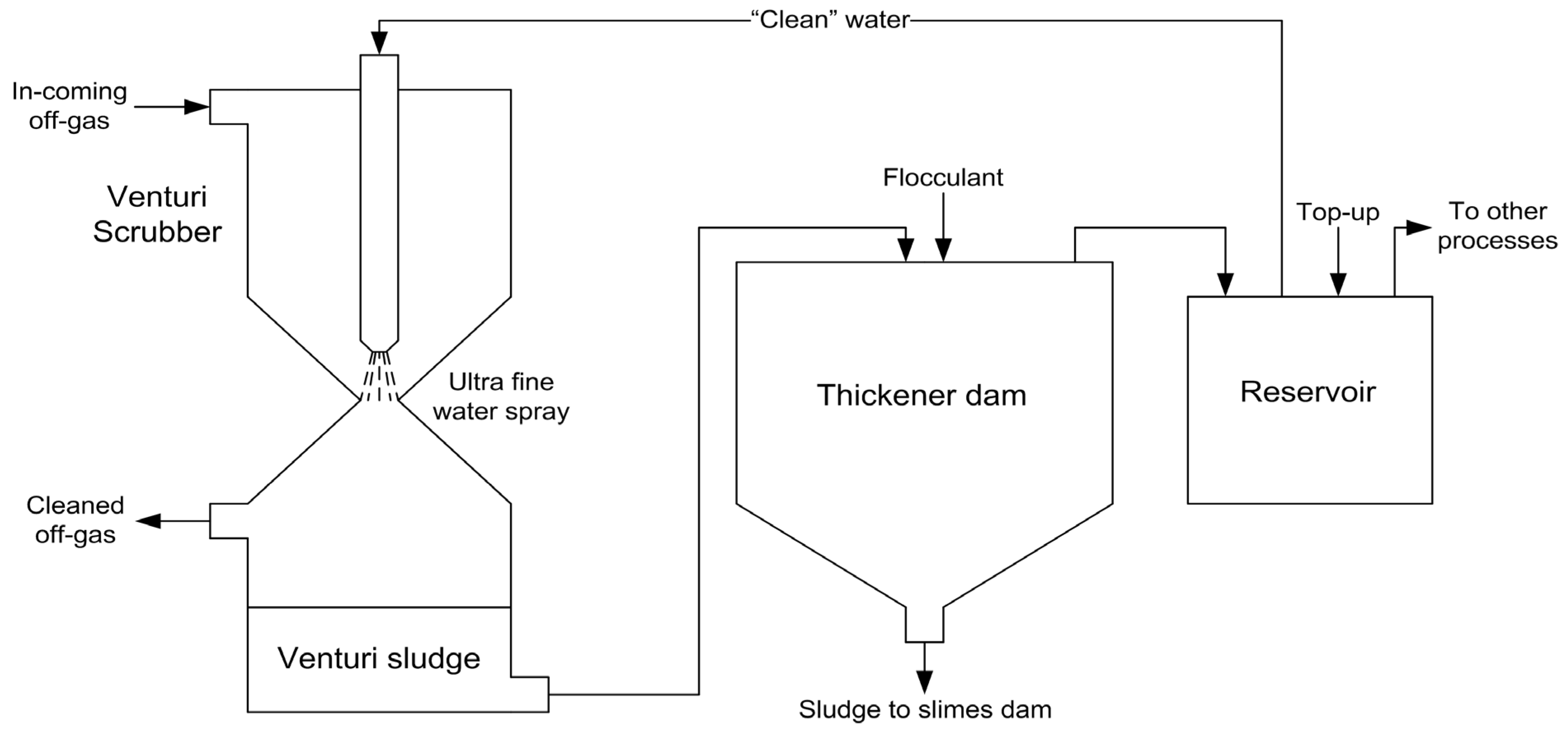
3.4.1. Closed SAF Operation Consuming a Pre-Reduced or Oxidative Sintered Pelletized Feed, Coupled with Venturi Off-Gas Scrubbers

In terms of waste generation, both of the FeCr production processes are similar and consist of the same process steps, i.e., Process Steps 1, 2, and 7–9 in Figure 9. Screened furnace feed materials, such as ores, fluxes, and reductants, and hot pre-reduced pellets (in certain cases, a fraction of cold pre-reduced pellets), are supplied to closed SAFs (Process Step 1, Figure 9). During smelting operations, the formed CO-rich off-gas is continuously removed from the furnace. The extracted off-gas contains a certain amount of fine solid particulate matter, which is removed from the off-gas before it is released into the atmosphere. This is achieved by off-gas scrubbing using wet venturi scrubbers (Process Step 2, Figure 9) [15,77,87]. Figure 10 shows a schematic illustration of the venturi scrubbing process and the handling of the venturi scrubber sludge and process water [20].
The incoming off-gas, before reaching the off-gas scrubbing process, is between 600–1000 °C and contains between 35–45 g·Nm−3 of solid material. The off-gas is scrubbed with 3–7 L of water per 1 Nm3 of off-gas at a pressure of 30 bar [82]. During scrubbing, the water undergoes cloud-type atomization, which forms liquid droplets with diameters of <10 µm [88]. These microsized droplets allow for intimate contact between the particulate matter and the droplets, resulting in the removal of 99.9% of particulate matter from the off-gas. The initial off-gas particulate matter content of 35–45 g·Nm−3 is therefore reduced to between 50–100 mg·Nm−3.
The remaining particles are typically <1 µm and difficult to remove from the off-gas stream by venturi scrubbing. Sintered filters can remove the remaining ultra-fine particulate matter [82], but such filters are usually not used by South African FeCr producers [23]. Generated venturi sludge formed during off-gas scrubbing collects at the bottom of the venturi scrubber and is subsequently pumped into a thickener. The venturi sludge is then allowed to separate from the scrubber water through settling and this process is typically accelerated by utilizing flocculants. The venturi sludge is generally considered a hazardous material and is treated for the presence of Cr(VI) [15]. Thereafter, the venturi sludge is discarded in fit-for-purpose slimes dams after being dewatered. The so-called clean process water is pumped into a reservoir and is continuously topped up to maintain a certain volume. This process water is either used elsewhere on-site or re-used in the scrubbing process.
In some cases, the scrubbed off-gas is used as an energy source on-site, e.g., during pellet sintering, material drying, drying of runners in the tapping area, or to heat ladles. The primary off-gas constituent, i.e., CO(g), is highly toxic to humans [89] and explosive [82] in air within a range of 12–75 vol.%, and unused CO(g) containing off-gas is typically flared on top of furnace stacks. By doing so, large quantities of energy in the form of heat are wasted. Alternative uses of CO-rich off-gas in discussed in Section 5.1.
To recover the molten constituency, i.e., molten FeCr and slag, the closed SAFs are tapped intermittently (Step 7, Figure 9). Furnace tapping is commonly carried out when a certain amount of electricity has been consumed or at fixed time intervals. Each SAF has a minimum of one taphole, which is a specially designed refractory inset in the furnace wall with a circular opening. After each tap, the taphole is plugged using specialized refractory clay. Both FeCr and slag are tapped through the same taphole [14].
The tapped molten FeCr is then granulated/cast (Step 8, Figure 9) according to the client’s prerequisites. The molten slag phase is allowed to solidify either naturally or by water spraying. The solidified slag is then broken into smaller pieces, crushed, and sent to a metal recovery plant (Step 9, Figure 9). The remaining FeCr is typically recovered from the slag with magnetic separation or jigging and sold. The slag is however either stockpiled or utilized in various commercial applications. By volume, slag is a significant waste material [77]; however, it was not considered further in this study since various uses thereof already exist and it has received significant research attention [33,90,91,92,93,94,95,96,97,98,99,100].

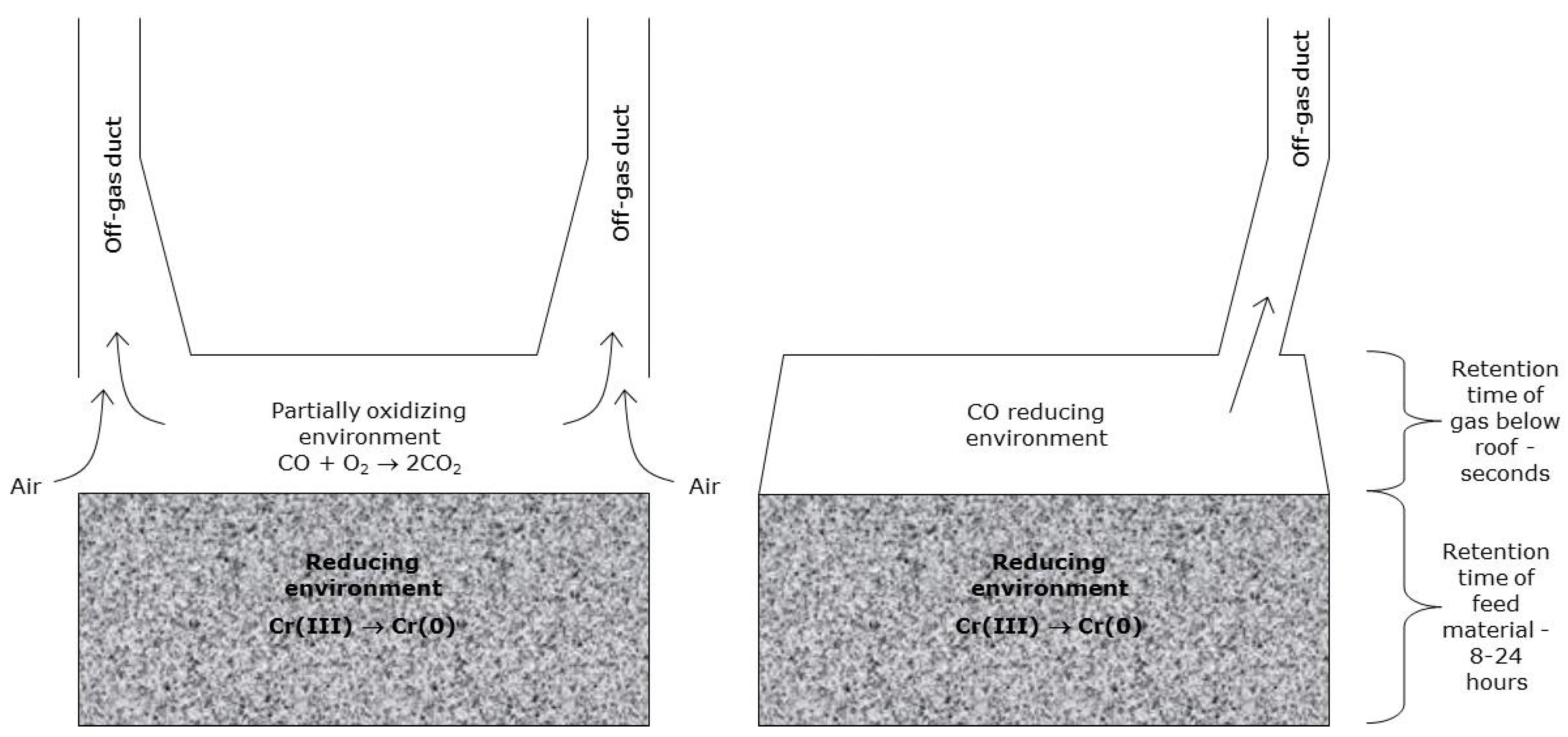
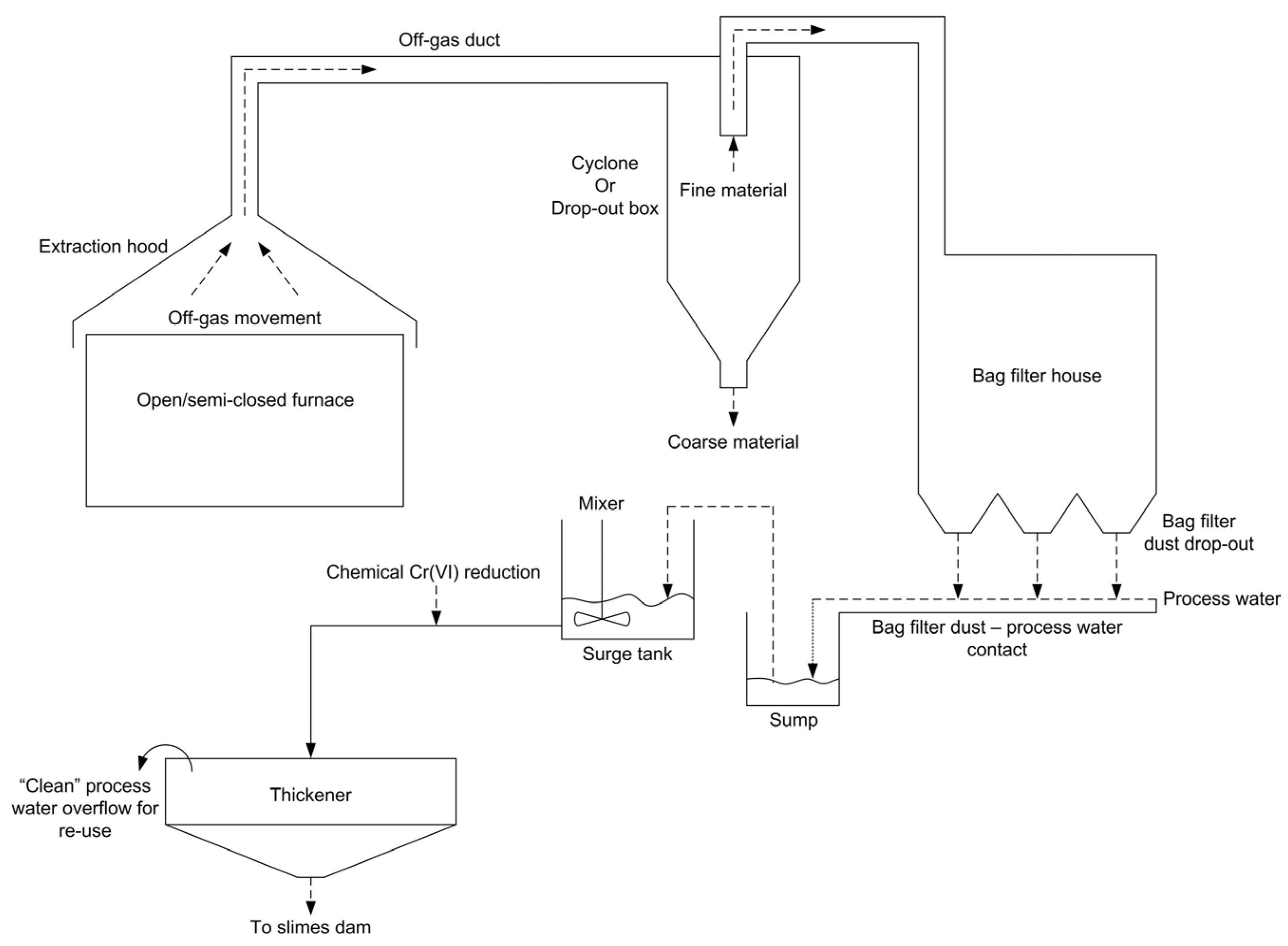
3.4.2. Semi-Closed SAF Operations, Coupled with Bag Filter Off-Gas Treatment

This smelting route comprises Steps 3–9 in Figure 9. The CO-rich off-gas generated during semi-closed SAF smelting (Step 3, Figure 9) permeates through the furnace bed, whereafter it is unavoidably ignited above the furnace bed due to air ingress into these types of furnaces. The combusted off-gas is continuously extracted and passed through bag filters before being released into the atmosphere [14,23,78]. Before bag filtering, the off-gas is partially cleaned by passing it through a cyclone or drop-out box (Step 4, Figure 9), during which the majority of coarse material is separated from the off-gas. Recovered coarse material can then either be discarded or recycled. Hereafter, the off-gas passes through the aforementioned bag filters located in a baghouse (Step 5, Figure 9). Here, dry and fine material is retained in specially designed bag filters. The collected dust, referred to as bag filter dust (BFD), should be contacted with water immediately after being collected to prevent wind dispersal and dust spillages [15]. The generated sludge which forms when the BFD is contacted with water is chemically treated to reduce Cr(VI) to Cr(III) and is thereafter discarded in fit-for-purpose slimes dams (Step 6, Figure 9). The BFD treatment process is shown in Figure 11 [78].
A relatively major environmental concern for FeCr producers is the presence of relatively high Cr(VI) concentrations in slimes dams, since materials discarded in slimes dams consist of venturi sludge and/or BFD, after being treated for Cr(VI). The presence of Cr(VI) suggests that the currently applied process (shown in Figure 11) does not mitigate the total Cr(VI) content present in BFD. Therefore, unextracted Cr(VI) is inadvertently stockpiled in slimes dams, will likely be solubilized when exposed to terrestrial conditions, and could be released into the environment. The release of Cr(VI) into the environment as a direct result of FeCr production is extremely detrimental to the ambient environment [101,102]. BFD was therefore considered a critical waste material and is further discussed in Section 4.
The furnace tapping (Step 7, Figure 9), FeCr (Step 8, Figure 9), and slag (Step 9, Figure 9) handling procedures are similar to what was discussed in Section 3.4.1.

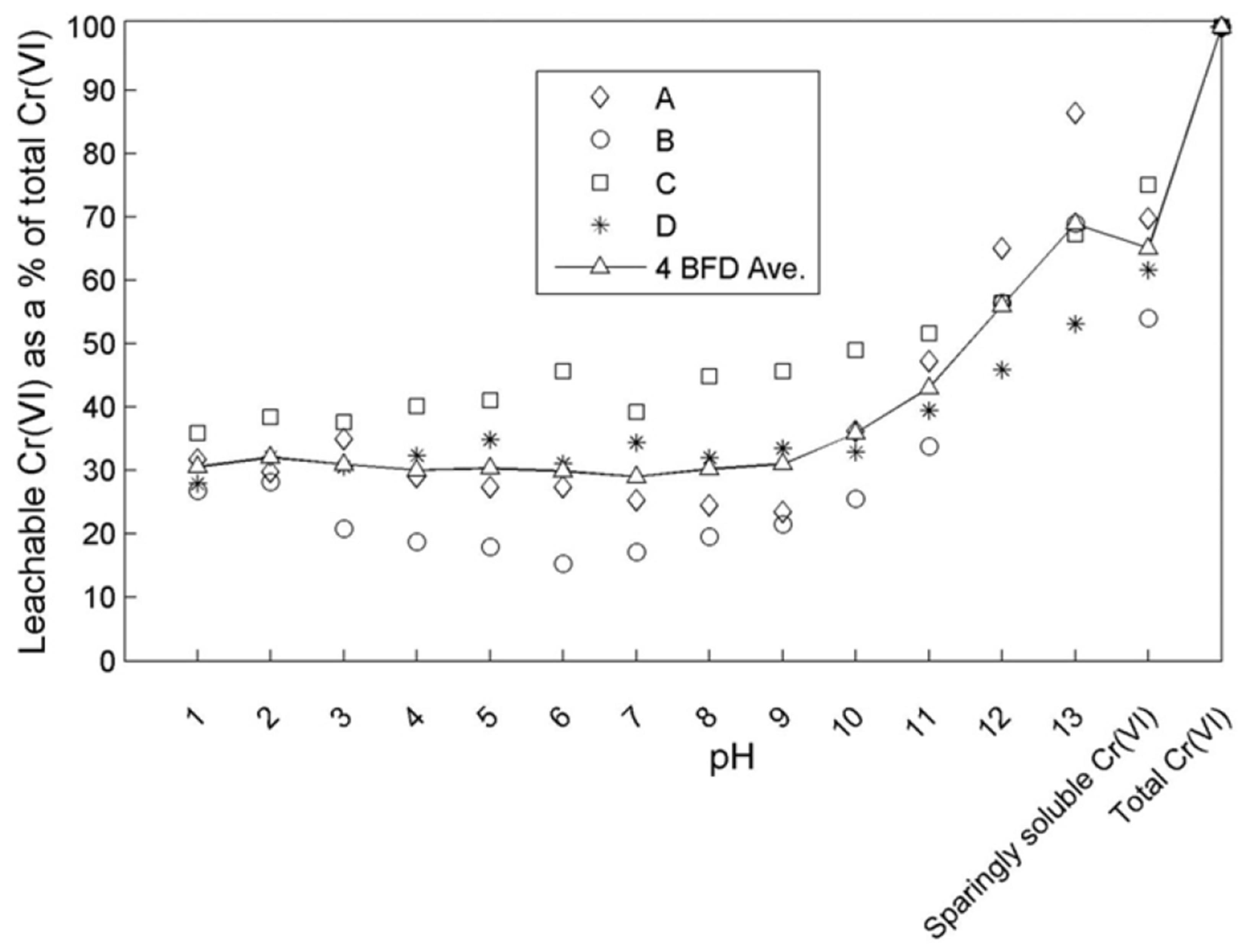
4. Cr(VI) in the FeCr Industry

The Cr(VI) containing waste generated during FeCr production is by far the most environmentally and ecologically concerning by-product due to its carcinogenic nature and its mobility in groundwater. A relatively recent review by Beukes et al. (2017) summarized the importance of Cr(VI) environmental practices related to chromite mining and smelting and the relevance thereof to the so-called Ring of Fire, Canada [30]. Therefore, Cr(VI) chemistry-related topics, e.g., natural occurrence/formation of Cr(VI), the mobility of Cr-species, and the atmospheric Cr-cycle, are not discussed here. Rather, only the processes that generated Cr(VI) and the current treatment approaches are summarized here.
The main Cr(VI)-generating processes include dry milling of chromite (Section 3.2.1) and semi-closed SAF operations (Section 3.4.2). By comparison, BFD generated during the cleaning of off-gas originating from semi-closed SAF operations contains by far the highest levels of Cr(VI) [51] (as previously shown in Figure 11 [78]) and is, therefore, the only material discussed here in detail.
As mentioned earlier, BFD should be contacted with water as soon as possible to limit dust dispersion. Hereafter, the Cr(VI) containing water is chemically treated to remove Cr(VI), using for instance chemical reduction using Fe(II) as the reductant. The resulting water-contacted BFD is stockpiled in slimes dams. Though other water materials are co-disposed on the slimes dams, such as venturi sludge [30], such materials do not contribute significantly to the total Cr(VI) content of slimes dams.
It has been reported by FeCr producers that Cr(VI) leaches from slimes dams over extended periods, which indicates that the currently applied Cr(VI) treatment practices do not extract the total Cr(VI) content from BFD [30].
A study by Gericke (1995) showed that Cr(VI) is extracted from BFD after 24 h when contacted with a pH 2 to 6 solution [87]. Maine et al. (2005) showed that the total Cr(VI) content can be extracted from BFD by contacting the BFD with neutral water for >100 h [103]. Bulut et al. (2009) found that Cr(VI) is fully solubilized after 30 min of leaching regardless of the solution pH [104]. However, in practice, the use of pH-altered process water and extensive contact times are not generally considered by industry.
A study by Du Preez et al. (2017) determined the water-soluble, sparingly water-soluble, and water-insoluble fractions of the Cr(VI) content present in BFD. It was found that the water-soluble, sparingly water-soluble, and insoluble Cr(VI) contents account for 31, 34, and 35%, respectively [78]. Figure 12 shows the solubility of Cr(VI) compounds present in BFD as a function of pH, as well as the quantified sparingly water soluble and total Cr(VI) contents.
The BFD stockpiled in slimes dams contains a relatively significant amount of Cr(VI), ranging between 150–340 mg Cr(VI)/kg BDF (based on four BFDs obtained from four different South African FeCr producers) [78]. Du Preez et al. identified that the water-soluble Cr(VI) species is likely Na2CrO4 and that the sparingly water-soluble Cr(VI) species can be extracted using a pH 13 solution. The water-insoluble Cr(VI) content is less problematic, as its solubilization during storage is unlikely [78]. It is also noted that Fe(II) is mostly used during Cr(VI) reduction and that Fe(II) is rapidly oxidized by oxygen at high pH levels. Therefore, the sparing water-soluble Cr(VI) compounds are of concern as it is likely that they account for the problematic systematic release of Cr(VI) from slimes dams.
Suitable Cr(VI) extraction processes cannot be developed if the relevant Cr(VI) species (i.e., the cationic association of the sparingly water-soluble chromate compounds) are unidentified. It is also likely that the Cr(VI) speciation will largely be affected by the furnace feed material composition. Nevertheless, from an environmental point of view, Cr(VI) management requires significant attention.

5. Propositions for Alternative Waste Management

From the preceding sections, the various wastes generated during FeCr production were identified. The wastes of particular concern, and the specific processes generating these wastes, are discussed in this section. The wastes and processes discussed in this section include CO-rich off-gas and alternative approaches to utilize these gasses, the potential for low-temperature chromite agglomeration, and the partial replacement of C-reductants with alternative reductants, e.g., hydrogen.

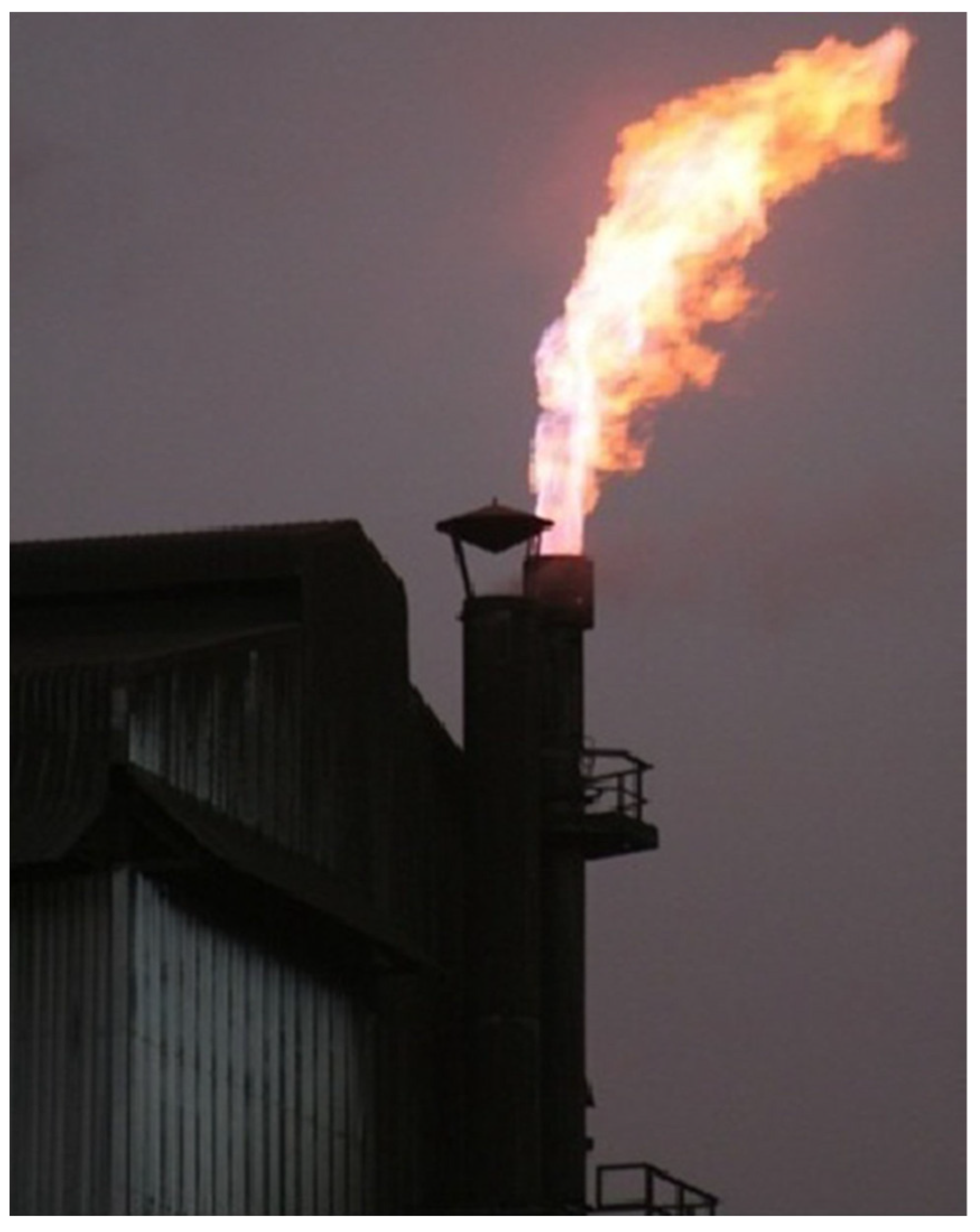
5.1. CO-Rich Off-Gas

During FeCr production, furnace off-gas is of particular environmental concern due to the significant amounts of gaseous C being released. The off-gas from closed SAF and closed DC arc furnace smelting contains various concentrations of energy containing CO(g) and H2(g) [82,105], and unused cleaned off-gas is typically flared on top of an SAF stack to oxidize the CO(g) to CO2(g) and H2(g) to H2O(g) [105]. This is however not the case in developed countries as the energy associated with these SAFs is typically utilized (e.g., boilers) and significant efforts are made in carbon capture and storage (CCS) and looping (CCL) [106].
As mentioned in Section 3.4.1, the main reasons why CO-rich off-gas is usually not stored in large volumes on-site are its toxicity to humans via inhalation [89] and its explosive nature [82]. In South Africa, the majority of CO-rich off-gas is flared on top of a purposefully designed closed SAF stack, as shown in Figure 13 [107,108].
The composition and volume of off-gas from closed SAF operations are affected by a variety of properties, e.g., process metallurgical condition, furnace design and operating regime, feed material specifications, and pre-treatment methods (if any) [23]. Closed SAF off-gas has been reported to consist of 75–90% CO, 2–15% H2, 2–10% CO2, and 2–7% N2. It is estimated that between 650–750 Nm3 of off-gas is generated per ton FeCr [82]. Closed DC arc furnace off-gas compositions have been reported to be 58–64% CO, 2–6% CO2, 26–34% H2, 0–5% N2, and <1% O2 [105].
Niemelä et al. (2004) estimated that for each ton of FeCr produced in a closed SAF, the accompanying generated CO(g) has an energy value of between 2.0–2.3 MWh, depending on the CO(g) and H2(g) contents. Thus, a significant amount of energy is lost during CO-rich off-gas flaring [82,105]. Some FeCr producers utilize between 30–35% of CO-rich off-gas as an on-site energy source for, e.g., chromite pellet sintering/pre-reduction, ladle heating, material drying, and/or pre-heating furnace charge [82]. It has been estimated that the amount of thermal energy utilized by these procedures may be considered negligible when compared to the potential heat associated with CO-rich off-gas [105].
As a result of increased environmental concerns, e.g., reduction in carbon footprint and carbon tax, and increased pressure on profitability, e.g., increasing electricity costs, methods have been developed in an attempt to utilize CO-rich off-gas. Such methods include using cleaned off-gas as a fuel in a so-called CO-gen, which is defined as internal combustion engines utilizing CO- and H2-containing off-gas as a fuel source to drive electrical power-producing alternators [105], production of value-added chemicals through CO-rich off-gas fermentation with bacteria [109], and steam generation through the combustion of off-gas for steam turbine electricity generation [110]. Large-scale industrial applications thereof are however limited as each of the aforementioned methods has associated operational complications. More so, off-gas should ideally be consumed as soon as possible to mitigate risks associated with their toxic and explosive nature.
Du Preez et al. (2018) proposed converting the thermal energy associated with the CO-rich off-gas into chemical energy in the form of SiC. The SiC could subsequently be used as a co-reductant during chromite smelting. More so, SiC can be produced from undersized quartz, typically classified as waste material by certain chromite smelters [111].
Reaction 4 showed the interaction between SiO2 and C to generate SiO(g). The formation of SiC using the generated SiO(g) and C is shown in Reaction 9, and the reactions between FeO and Cr2O3 are given by Reactions 10 and 11:
SiO(g) + 2C = SiC + CO(g), ∆H°298K = −79.52 kJ/mol  (Reaction 9)
3FeO + SiC = 3Fe + SiO2 + CO(g), ∆H°298K = −154.33 kJ/mol  (Reaction 10)
Cr2O3 + SiC = 2Cr + SiO2 + CO(g), ∆H°298K = 187.86 kJ/mol  (Reaction 11)
Reaction 9 shows that SiO(g) reacts exothermically with C to form SiC and CO(g). Reactions 10 and 11 show that the by-products are SiO2 and CO(g) when FeO and Cr2O3 are reacted with SiC. The SiO2 is ejected to the slag phase, whereas the CO(g) permeates upward through the material bed as per usual, which under certain conditions acts as a pre-reductant of the materials in the upper part of the furnace (as previously shown in Reactions 6–8). Reaction 10 shows that the reaction between FeO and SiC is exothermic, whereas the reaction between Cr2O3 and SiC is endothermic (Reaction 11). It is noted that the ∆H°298K value for Reaction 11 is lower than that of Reaction 3, suggesting that the interaction between Cr2O3 and SiC will require less energy, i.e., proceed at a lower temperature when compared to the interaction between Cr2O3 with C.
The formation of SiC does however require high temperatures, as can be deduced from the relatively high ∆H°298K value shown in Reaction 4. This large energy requirement is the reason why SiC is not used as a reductant in the FeCr industry, i.e., a significant amount of energy is required to synthesize SiC from quartz. Du Preez et al. (2018) however showed that the temperature at which CO-rich off-gas is flared is sufficient to enable the reaction between quartz and C to produce SiC. Figure 14 shows the formed SiC particles using undersized quartz and carbonaceous reductant [111].
It is noted that the SiO(g) phase was present in the process proposed by Du Preez et al. (2018) [111]. It was assumed that if a sufficient layer of coarse reductant was placed on top of the quartz and reductant mixture, the majority of SiO(g) would condensate and react on the surface of the layered reductant.
Though many applications exist for the utilization of off-gas as an energy carrier, it is scarcely employed by South African FeCr producers. In the past, electricity prices in SA were sufficiently low for producers to forego energy recovery from the off-gas. However, the nominal price for electricity increased by 520% between 2007 and 2021 [112]. Notwithstanding environmental considerations, FeCr producers will need to alter their approach to off-gas management and implement energy recovery methods to increase profit margins.

5.2. Low-Temperature Chromite Agglomeration

As shown earlier in Section 3.2, pelletization of undersized chromite employed locally (and internationally) requires elevated temperatures, e.g., 1300–1400 °C for oxidative sintering, and 1400–1500 °C for pre-reduction.
It is understood that the agglomerated chromite has to meet certain specifications before it can be safely smelted in an SAF. These specifications include the following: (i) the agglomerate must be mechanically strong as to prevent the reformation of fines in the upper part of the furnace bed; (ii) the binder addition must be kept to a minimum as to limit Cr-dilution, with additions up to 3 wt% generally regarded as acceptable; (iii) the binder should not contribute to the formation of environmentally adverse compounds within the SAF, specifically Cr(VI); (iv) the binder must not adversely affect the furnace chemistry (e.g., for a certain smelting regime, the basicity factor is typically predictable); and (v) the binder should ideally not contribute to the Si content of the produced FeCr [113].
Organic pellet binders, e.g., cellulose, molasses, wheat flour, lactose monohydrate, dextrin, and corn starch, have been widely investigated for Fe ore pelletization [114,115,116]. However, these binders have low decomposition temperatures, which will result in the reformation of chromite fines in the upper part of the furnace bed, increasing the risk of bed sintering. More so, pellets with a high moisture and/or volatile content are susceptible to bursting when exposed to high temperatures, which results in operational difficulties [31,117].
In the Fe-ore smelting industry, the use of ordinary Portland cement has been investigated, and several such cement-based pelletization/briquetting processes have been developed [118,119,120,121]. However, the use of cement as a binder is complicated by excessively long curing times of up to 28 days, as well as a minimum addition of 10 wt%. In addition to this, cement is classified as a low-temperature binder (e.g., decomposition at approximately 700 °C), and the decomposition of cement-bonded agglomerates will result in the reformation of fines. More so, considering that cement comprises mainly alkali and alkali earth metals, the inclusion thereof will increase the total alkali content of the respective SAF. In the presence of oxygen, sodium chromate (Na2CrO4) is produced by the alkaline roasting of chromite [122]. Therefore, the inclusion of cement will result in elevated Cr(VI) formation during semi-closed SAF operations, which is already associated with elevated Cr(VI) generation.
A study by Du Preez et al. (2020) investigated a variety of binders for the pelletization processes as well as a subsequent low-temperature curing method. The use of meta-sodium silicate, precipitated SiO2, and an alkaline activator was identified as an acceptable binder combination, and pellet curing at 75 °C was used to produce mechanically strong pellets [113]. The addition of SiO2 and the use of an alkaline activator likely promoted geopolymerization of the Al- and Si-oxides present in the pelletization material, which contributed to the mechanical strength of the cold-bonded pellets. Figure 15 shows pellets with a compressive strength of 3.12 ± 0.10 kN were produced using a combination of 3 wt% sodium silicate—3 wt% SiO2, a 6 wt% moisture addition using a 4 M KOH solution, and a curing temperature of 75 °C. These pellets greatly exceeded the compressive strength of 1.54 ± 0.50 kN determined for pre-reduced pellets obtained from a South African FeCr producer [113].
Cold-bonded pelletization is typically not considered on a large scale as existing pellet curing infrastructure, i.e., pre-reduction and oxidative sintering, is well established and understood. More so, these curing routes allow pellet outputs (tons/h) to ensure continuous SAF operations. There is however some potential for further development of cold-bonded pellets, as such pellets which are not produced via traditional means, i.e., pre-reduced and oxidative sintering, could be designated for semi-closed SAF operations, as such SAFs typically operate on lumpy ore, which accounts for a small fraction of recovered chromite, and have strict limitations on the number of fines they can accommodate.

5.3. Hydrogen as a Reductant

As indicated earlier, the removal of oxygen from metal oxides using C as the reductant generates significant amounts of CO2. The replacement, or at least partial replacement, of C by hydrogen has received attention in recent years, as the only resulting by-product is water vapor. The use of hydrogen has become more and more attractive as hydrogen generation processes mature, particularly in terms of production cost ($/kg H2) and production scale (>>kW size electrolyzers, if green hydrogen is considered). The production of hydrogen is only considered green if it is produced from water using renewable energy sources (specifically photovoltaics and wind within the South African landscape). In 2016, the majority of globally produced hydrogen was from steam methane reformation (48%), crude oil cracking (30%), and coal gasification (18%). The remaining 4% of hydrogen originates from the chlor-alkali industry (3%, hydrogen as a by-product) and from electrolysis (1%) [123].
Hydrogen is typically used in the refining of base metals [124]. Though the implementation of hydrogen in the reduction of metal oxides is many years from maturing, the use thereof in Fe-ore (ores comprising mainly of Fe-oxides) smelting and the steel industry has advanced significantly in many developed countries [125,126,127,128,129,130,131]. Additionally, hydrogen has shown potential as a pre-reductant in the ferromanganese industry, metalizing Fe-oxides, reducing higher Mn-oxides to lower oxidation states [132,133,134,135,136], and having an effect on the reaction rates and mechanisms during Si processing [137,138]. More so, using hydrogen to produce fossil-free Fe is currently a major focus in Europe as a means of decarbonizing the industry [139,140].
The total replacement of C by hydrogen (in a gaseous form) in the smelting industry is both thermodynamically limiting and practically challenging [86,141], as stable metal oxides are resistive to gaseous hydrogen-based reduction. Nevertheless, the use of alternative smelting methods, e.g., plasma-based smelting [142,143,144,145,146,147], has been considered as a possible alternative to the traditional smelting methods of stable metal oxides.
An Ellingham diagram was compiled using the thermo-chemical software package HSC 9 showing the change in ∆G of the various reduction reactions for Fe-oxides, Cr2O3, and pure chromite. The reduction potential of both CO and H2 are also added to exemplify their activity as reductants (i.e., their potential to remove one mole of O2 from the relevant metal oxide). Figure 16 shows the Ellingham diagram.
A variety of deductions that can be made from Figure 16 are listed as follows: (i) the ∆G° slope of the reaction between H2(g) and O2(g) has a declined slope, which is indicative that H2(g) becomes less active as a reductant with an increase in reaction temperatures. The inverse is true for the reaction between C and O2(g), which has an inclined slope; (ii) during H2-based reduction, the H2-based reduction of Fe2O3 to FeO proceeds at a temperature as low as approximately 330 °C; (iii) the ∆°G of FeO and H2(g) do not intercept; rather, they share proximity, which would suggest that their interaction would be dictated by kinetic considerations rather than thermodynamics; (vi) the reduction of Cr2O3 by H2(g) is thermodynamically unfavored; (v) the complete reduction of FeCr2O4 to Cr and Fe by H2 is thermodynamically unfavored, while the partial reduction of FeCr2O4 to Fe and Cr2O3 is also unfavored but less so when compared to its complete reduction.
Excluding the environmental issues related to gaseous C generation during smelting, the procurement of high-quality C reductants, specifically in South Africa, has become less and less consistent and reliable. In some cases, FeCr smelters are forced to use available reductants rather than high-quality reductants. For instance, the use of coke as a reductant is no longer a cost-effective reductant as it has become more and more expensive and difficult to source [37]. Thus, the reliance of an FeCr producer on the quality of C-reductants used can partially be mitigated by employing hydrogen.
The use of thermodynamic predictions is a valuable tool when investigating the feasibility of using molecular hydrogen as a chromite reductant. For this purpose, the formula for pure chromite is used, as thermodynamic calculations cannot accommodate the general formula, i.e., (Mg, Fe2+)(Al, Cr, Fe3+)2O4. The reactions considered for chromite’s partial metallization (Reaction 12) and full metallization (Reaction 13) are as follows:
FeCr2O4 + H2(g) = Fe + Cr2O3 + H2O(g), ∆H°298K = 66.32 kJ/mol  (Reaction 12)
FeCr2O4 + 4H2(g) = Fe + 2Cr + 4H2O(g), ∆H°298K = 478.20 kJ/mol  (Reaction 13)
There is a significant difference in the ∆H°298K of Reactions 12 and 13, which suggests that the Cr-oxide constituency of the considered pure chromite is highly resistive to reduction. Davies et al. (2022) showed that a significant fraction of the Fe-oxide constituency can be metalized using hydrogen, whereas the Cr-oxides remained unchanged. Davies et al. (2022) further presented a phase stability diagram for a (Cr, Fe)-H2-H2O system as a function of pH2 and pH2O at 1000 °C (Figure 17) [141].
In Figure 17, the black dotted line at log10pH2 = 0 equates to a pH2 = 1 atm. Where the black dashed line crosses the respective metallic phases, i.e., Cr and Fe, the reduction of the higher oxide phases to the metallic phase would thermodynamically occur, i.e., Cr2O3 to Cr and FeO to Fe, at the relevant temperature (1000 °C in this case). The vertical dashed colored lines indicate the pH2O required for the reaction to proceed. From the vertical lines, it can be seen that Fe metallization requires a relatively dry atmosphere with a pH2 between 0.1 and 1 atm, whereas Cr metallization would only be possible in an atmosphere technically void of any moisture, e.g., pH2O of 0.0001 atm. Therefore, excluding thermodynamic limitations, a back-reaction, defined as Cr0 reacting with in-situ formed H2O(g), is likely to occur at elevated temperatures [147]. Therefore, the use of gaseous hydrogen to metalize Cr2O3 would be nearly impossible from an industrial perspective. Thus, the reduction of the Fe-oxides present in chromite should be emphasized.
It is known that the high-temperature exposure of chromite results in the decomposition of its spinel structure. The phase decomposition of spinels proceeds according to relatively well-understood mechanisms and can be defined by Reaction (14) [84,148]:
(A)[B]2O4 = (AO) + [B2O3]  (Reaction 14)
In the case of pure chromite, FeCr2O4, the decomposition products are FeO and Cr2O3, i.e., (AO) and [B2O3], respectively [86,148]. However, during high-temperature decomposition and in the presence of oxygen, FeO is oxidized to Fe2O3. In addition, the Fe-oxide constituency of chromite, assuming complete oxidation, occurs as a segregated sesquioxide Fe-phase in the Fe3+ oxidation state.
Numerous studies have reported on the formation of an Fe-enriched phase, which forms a Widmanstätten-type pattern along the chromite particle grains and cleavage planes [11,83,84,85]. In most cases, the Cr-oxide constituency of the chromite occurs as an eskolaite-type phase (eskolaite-corundum solid solution, Cr1.4Al0.6O3) [141] due to the migration of Fe from the spinel. Nevertheless, the sesquioxide phase is the preferential site for Fe-oxide reduction by hydrogen [86] due to the lower energy requirement (from a thermodynamic perspective) to metalize the exsolved Fe-oxides when compared to spinel-bound Fe-oxides as shown in Figure 16.
As mentioned earlier, various studies have shown that oxidized chromite reduces at temperatures lower than that of normal chromite [45,81,85] when using carbonaceous reductants, which further emphasizes the effect oxidation has on chromite’s reducibility. When considering the two main pellet curing procedures used by industry (i.e., pre-reduction and oxidative sintering), using hydrogen as a reductant for pre-reduced pellets cannot be considered, as a significant fraction of the Fe-oxides is metalized during pre-reduction. Therefore, hydrogen can only be considered as a reductant for oxidatively sintered pellets, or lumpy ore before smelting in semi-closed SAFs.
In conclusion, hydrogen can be considered as a chromite pre-reductant to selectively metalize the Fe-oxides present in chromite. Hereafter, the FeCr producer has the option to either recover the Fe0 or subject the pre-reduced chromite to traditional smelting procedures without employing Fe recovery. The latter will forego the energy consumption required to reduce the Fe-oxides; however, some energy will still be consumed to liquefy the Fe0 (to form part of the FeCr liquous phase). Nevertheless, during SAF operations, less energy and carbonaceous reductant will be consumed during traditional smelting.

6. Conclusions

This review presents a synopsis of the various process steps used by industry in the beneficiation and smelting of chromite, as well as the waste materials generated for each of these process steps. By linking a specific process step to its relevant waste material, as well as the currently applied management of such wastes, the efficiency of these practices can be assessed. By doing so, it is possible to specifically identify if currently applied management is sufficient in achieving its intended purpose. A variety of materials were identified, ranging from low value but high quantity materials (e.g., low chromite content tailings generated during ore beneficiation) to low volume but high impact materials (e.g., Cr(VI) containing BFD generated during semi-closed SAF operations). The identified materials are summarized in the proceeding text.
It is shown that during the beneficiation of chromite ore, significant volumes of value-containing tailings (in the form of rejected chromite) are generated. Improving beneficiation circuits is complicated by variations in the physical and chemical composition of the relevant feed material. Therefore, beneficiation circuits cannot accommodate significantly dissimilar feeds as a specific beneficiation circuit comprises components intended for a feed with specific physical and chemical properties.
During the pellet pre-reduction process, ash originating from the combustion of pulverized coal results in the formation of a so-called damring within the interior of rotary kilns. Damrings are removed intermittently from such kilns. During this, the kiln is non-operational, resulting in the relevant SAFs consuming lumpy ore instead of reduced pellets. Inadvertently, such an SAF will have a lower metallurgical efficiency. By replacing such fuel with an alternative ashless fuel, e.g., CO-rich off-gas, damring formation would be significantly reduced. Though CO-rich off-gas is a potential fuel source, their combustion properties would not be completely efficient for pre-reduction purposes.
Undersized material originating from oxidative sintered pellet screening was identified as a potentially important material to be recycled. It comprises mainly partially oxidized chromite that can be reduced at lower temperatures when compared to normal chromite. Currently, this material is only recycled up to 4% by reintroducing the material during oxidative pellet sintering. The reasoning for the 4% limit is somewhat arbitrary and it is believed by industry that inclusions beyond 4% would adversely affect pellet mechanical strength. It has however been shown that up to 32% can be recycled while retaining or improving the mechanical strength.
Of particular concern is the inadvertent release of Cr(VI) from slimes dams post-Cr(VI) mitigation treatment. It was found that currently applied management only removes the water-soluble Cr(VI) constituency (approximately 31%) of the total Cr(VI) content present in BFD (the main Cr(VI) containing waste material). It is estimated that the sparingly water-soluble Cr(VI) content accounts for approximately 34% of the total Cr(VI) content and that this fraction is responsible for Cr(VI) post-treatment release from slimes dams. The remaining 35% of the total Cr(VI) content is water-insoluble and is unlikely to be released from slimes dams when exposed to terrestrial conditions.
The CO-rich off-gas originating from closed SAF operations are typically flared on furnace stacks, if not used immediately onsite. By doing so, significant amounts of energy are wasted. Though some processes exist to utilize energy associated with the CO(g), such processes are typically not employed by the South African FeCr industry. It was proposed that the CO(g) be used as a heat source for the production of SiC from undersized quartz (typically discarded) and undersized reductants (typically included as a pellet constituent). The produced SiC can in turn be used as a co-reductant during FeCr production. This approach foregoes the need to store the off-gas, as well as operational difficulties related to generating electrical power using boilers or CO-engines. As CO(g) is highly toxic and explosive, foregoing its storage is operationally attractive.
Low-temperature pelletization is another means to forego the need for the high curing temperatures associated with oxidative sintering and pre-reductive pellet production. This process would however make use of alternative binders (e.g., sodium silicate) instead of bentonite and attapulgite, an alkaline solution (e.g., KOH) instead of water, and the addition of SiO2. Though closed SAFs mainly use pelletized chromite, either as oxidatively sintered or pre-reduced pellets, and will be unlikely to accommodate pellets produced otherwise, semi-closed SAFs could be used to smelt pellets produced using a low-temperature pelletization method.
Lastly, the use of hydrogen as a reductant would abate a relatively significant amount of C dependence during FeCr production. The Fe-oxides present as part of the chromite spinel are more susceptible to reduction when compared to the Cr2O3 constituency. Considering that typical South African chromite contains between 41–44 wt% Cr2O3 and has Cr/Fe ratios of 1.3–1.5, hydrogen reduction of the Fe-oxides would not only reduce C-emissions but would also allow FeCr producers to recover metalized Fe from the hydrogen-treated chromite before traditional smelting procedures. This should be seen as an added benefit as producers are only renumerated for the Cr content of the produced FeCr, i.e., Fe is given away.
From this review, it may be concluded that certain wastes are of low interest to attend to, e.g., chromite-containing middlings and tailings, while others can be classified as important, e.g., by eliminating Cr(VI) release (from an environmental perspective) and facilitating energy recovery from CO-rich off-gas. There are numerous opportunities for research and development within the FeCr industry, specifically within South Africa. However, considering that SA chromite has a relatively high Fe-oxide content, the use of hydrogen is specifically of interest. Moreover, due to a continual decrease in the C-reductant quality experienced by the FeCr industry, turning to green hydrogen is a means to decouple (at least partially) FeCr production and C-consumption. Reducing C-emissions is a global objective and considering the abundance of renewable energy sources in South Africa (sunlight, wind), producing and using green hydrogen as a reductant should be considered a high priority by the FeCr industry.

Author Contributions

Conceptualization, S.P.d.P., J.P.B. and P.G.v.Z.; methodology S.P.d.P. and J.P.B.; software, S.P.d.P., J.P.B. and M.T.; validation, J.P.B., E.R. and P.G.v.Z.; formal analysis, S.P.d.P. and T.P.M.v.K.; investigation, S.P.d.P. and J.P.B.; resources, J.P.B. and M.T.; data curation, S.P.d.P., J.P.B. and P.G.v.Z.; writing—original draft preparation, S.P.d.P., J.P.B., P.G.v.Z., T.P.M.v.K., E.R., M.T., K.M. and D.G.B.; writing—review and editing, S.P.d.P. and J.P.B.; visualization, S.P.d.P. and J.P.B.; supervision, J.P.B., P.G.v.Z., M.T.; project administration, J.P.B., P.G.v.Z., D.G.B. and M.T.; funding acquisition, J.P.B., P.G.v.Z., D.G.B. and M.T. All authors have read and agreed to the published version of the manuscript.

Funding

The financial assistance of the National Research Foundation (NRF), Grant Number 101345, is hereby acknowledged. Opinions expressed and conclusions arrived at are those of the authors and are not necessarily to be attributed to the NRF. Financial support received by the Research Council of Norway (RCN) as the THANOS project (INPART Project 309475), the Department of Science and Innovation, South Africa, and the HySA Infrastructure Centre of Competence, South Africa, through the KP5 program, are also acknowledged.

Data Availability Statement

No new data were created or analyzed in this study. Data sharing is not applicable to this article.

Acknowledgments

Not applicable.

Conflicts of Interest

The authors declare no conflict of interest.

References

  1. Motzer, W.E.; Engineers, T. Chemistry, Geochemistry, and Geology of Chromium and Chromium Compounds. Chromium (VI) Handbook; CRC Press: Boca Raton, FL, USA, 2004; pp. 23–88. [Google Scholar]
  2. Nriagu, J.O.; Nieboer, E. Chromium in the Natural and Human Environments; John Wiley & Sons: Hoboken, NJ, USA, 1988; Volume 20. [Google Scholar]
  3. Haggerty, S.E. Oxide mineralogy of the upper mantle. Rev. Mineral. Geochem. 1991, 25, 355–416. [Google Scholar]
  4. Paktunc, A.; Cabri, L. A proton-and electron-microprobe study of gallium, nickel and zinc distribution in chromian spinel. Lithos 1995, 35, 261–282. [Google Scholar] [CrossRef]
  5. ICDA. Energy Update—November 2013; International Development Association: Paris, France, 2013. [Google Scholar]
  6. ICDA. Statistical Bulletin; International Chromium Development Association: Paris, France, 2013. [Google Scholar]
  7. ICDA. Chrome Ore—Global Overview of the Chrome Ore Market; International Chromium Development Association: Paris, France, 2013. [Google Scholar]
  8. Statista. Global Stainless Steel Melt Shop Production from 2005 to 2021. Available online: https://www.statista.com/statistics/223028/world-stainless-steel-production/#:~:text=In%202021%2C%20global%20stainless%20steel,compared%20to%20the%202020%20volume (accessed on 12 May 2023).
  9. Cramer, L.A.; Basson, J.; Nelson, L.R. The impact of platinum production from UG2 ore on ferrochrome production in South Africa. J. S. Afr. Inst. Min. Metall. 2004, 104, 517–527. [Google Scholar]
  10. Murthy, Y.R.; Tripathy, S.K.; Kumar, C.R. Chrome ore beneficiation challenges and opportunities—A review. Miner. Eng. 2011, 24, 375–380. [Google Scholar] [CrossRef]
  11. Glastonbury, R.I.; Beukes, J.; Van Zyl, P.; Sadikit, L.; Jordaan, A.; Campbell, Q.; Stewart, H.; Dawson, N. Comparison of physical properties of oxidative sintered pellets produced with UG2 or metallurgical-grade South African chromite: A case study. J. S. Afr. Inst. Min. Metall. 2015, 115, 699–706. [Google Scholar] [CrossRef]
  12. Fowkes, K. Is there a limit to the market share of South African chrome units? In Proceedings of the Metal Bulletin 7th South African Ferroalloys Conference, Johannesburg, South Africa, 4 September 2014. [Google Scholar]
  13. Kleynhans, E.L.J. Development and Improvement of Pre-Treatment Technologies to Enhance Ferrochrome Production; North-West University: Potchefstroom, South Africa, 2016. [Google Scholar]
  14. Riekkola-Vanhanen, M. Finnish Expert Report on Best Available Techniques in Ferrochromium Production; Finnish Environment Institute: Helsinki, Finland, 1999. [Google Scholar]
  15. Beukes, J.P.; Van Zyl, P.G.; Ras, M. Treatment of Cr(VI)-containing wastes in the South African ferrochrome industry—A review of currently applied methods. J. South. Afr. Inst. Min. Metall. 2012, 112, 347–352. [Google Scholar]
  16. ICDA. Ferrochrome; International Chromium Development Association: Paris, France, 2013. [Google Scholar]
  17. Pariser, H.; Backeberg, N.; Masson, O.; Bedder, J. Changing nickel and chromium stainless steel markets—A review. J. South. Afr. Inst. Min. Metall. 2018, 118, 563–568. [Google Scholar] [CrossRef] [Green Version]
  18. Jones, R. Pyrometallurgy in Southern Africa; Southern African Institute of Mining and Metallurgy: Johannesburg, South Africa, 2011. [Google Scholar]
  19. Howat, D.D. Chromium in South Africa. J. South Afr. Inst. Min. Metall. 1994, 86, 37–50. [Google Scholar]
  20. Du Preez, S.P. Ferrochrome Waste Management: Addressing Current Gaps; North-West University: Potchefstroom, South Africa, 2018. [Google Scholar]
  21. Soykan, O.; Eric, R.; King, R. Kinetics of the reduction of Bushveld complex chromite ore at 1416 C. Metall. Trans. B 1991, 22, 801–810. [Google Scholar] [CrossRef]
  22. Basson, J.; Curr, T.; Gericke, W. South Africa’s ferro alloys industry-present status and future outlook. In Proceedings of the Eleventh International Ferro Alloys Congress, New Delhi, India, 18–21 February 2007; pp. 3–24. [Google Scholar]
  23. Beukes, J.P.; Dawson, N.F.; Van Zyl, P.G. Theoretical and practical aspects of Cr(VI) in the South African ferrochrome industry. J. South. Afr. Inst. Min. Metall. 2010, 110, 743–750. [Google Scholar]
  24. Kleynhans, E.L.J. Unique Challenges of Clay Binders in a Pelletised Chromite Pre-Reduction Process—A Case Study. Master’s Thesis, North-West University, Potchefstroom, South Africa, 2011; p. 25. [Google Scholar]
  25. Xiao, Z.; Laplante, A. Characterizing and recovering the platinum group minerals—A review. Miner. Eng. 2004, 17, 961–979. [Google Scholar] [CrossRef]
  26. Ringdalen, E.; Olsen, S.E. The effect of chromite ore mineralogy on reduction mechanisms and reducibility. In Proceedings of the INFACON 8, Beijing, China, 7–10 June 1998; Volume 8, pp. 147–152. [Google Scholar]
  27. Suzuki, A.; Yasuda, A.; Ozawa, K. Cr and Al diffusion in chromite spinel: Experimental determination and its implication for diffusion creep. Phys. Chem. Miner. 2008, 35, 433–445. [Google Scholar] [CrossRef]
  28. Canaguier, V. Synthesis and Reduction-Carburization of (Fe,Mg)(Cr,Al)2O4 Composite Spinel Solid Solution with CH4; Norwegian University of Science and Technology: Trondheim, Norway, 2018. [Google Scholar]
  29. Downing, J.H.; Deeley, P.H.; Fichte, R.M. Chromium and Chromium Alloys; Verlagsgeschellschaft mbH: Berlin, Germany, 1986; pp. 43–65. [Google Scholar]
  30. Beukes, J.P.; du Preez, S.P.; van Zyl, P.G.; Paktunc, D.; Fabritius, T.; Päätalo, M.; Cramer, M. Review of Cr (VI) environmental practices in the chromite mining and smelting industry–Relevance to development of the Ring of Fire, Canada. J. Clean. Prod. 2017, 165, 874–889. [Google Scholar] [CrossRef]
  31. Kleynhans, E.L.J.; Beukes, J.P.; Van Zyl, P.G.; Bunt, J.R.; Nkosi, N.S.B.; Venter, M. The Effect of Carbonaceous Reductant Selection on Chromite Pre-reduction. Metall. Mater. Trans. B 2017, 48, 827–840. [Google Scholar] [CrossRef]
  32. Eksteen, J.; Frank, S.; Reuter, M. Dynamic structures in variance based data reconciliation adjustments for a chromite smelting furnace. Miner. Eng. 2002, 15, 931–943. [Google Scholar] [CrossRef]
  33. Niemelä, P.; Kauppi, M. Production, characteristics and use of ferrochromium slags. In Proceedings of the INFACON XI, New Delhi, India, 18–21 February 2007; pp. 171–179. [Google Scholar]
  34. Barnes, A.; Muinonen, M.; Lavigne, M. Reducing Energy Consumption by Alternative Processing Routes to Produce Ferrochromium Alloys from Chromite Ore. In Proceedings of the Annual Conference of Metallurgists, Toronto, ON, Canada, 23–26 August 2015. [Google Scholar]
  35. Pan, X. Effect of South African Chrome Ores on Ferrochrome Production; ICMMMC: Johannesburg, South Africa, 2013. [Google Scholar]
  36. Makhoba, G.; Hurman Eric, R. Reductant characterization and selection for ferrochromium production. In Proceedings of the 12th International Ferroalloys Congress, Helsinki, Finland, 6–9 June 2010; Vartiainen, A., Ed.; Outotec Oyj: Helsinki, Finland, 2010; pp. 359–365. [Google Scholar]
  37. Erwee, M.; Swanepoel, S.; Reynolds, Q. The importance of controlling the chemistry of pre-oxidized chromite pellets for Submerged Arc Furnace FeCr smelting: A study on furnace Si control. In Proceedings of the 16th International Ferro-Alloys Congress (INFACON XVI), Virtual, 27–29 September 2021. [Google Scholar]
  38. Hayes, P. Aspects of SAF smelting of ferrochrome. In Proceedings of the INFACON X, Cape Town, South Africa, 1–4 February 2004; pp. 1–4. [Google Scholar]
  39. Xiao, Y.; Yang, Y.; Holappa, L. Tracking chromium behaviour in submerged arc furnace for ferrochrome production. In Proceedings of the Sohn International Symposium, Advanced Processing of Metals and Materials, San Diego, CA, USA, 27–31 August 2006; pp. 417–433. [Google Scholar]
  40. Xiao, Y.; Yang, Y.; Holappa, L.; Boom, R. Microstructure changes of chromite reduced with CO gas. In Proceedings of the INFACON XI, New Delhi, India, 18–21 February 2007; Volume 1, pp. 7–14. [Google Scholar]
  41. Neizel, B.; Beukes, J.; Van Zyl, P.; Dawson, N. Why is CaCO3 not used as an additive in the pelletised chromite pre-reduction process? Miner. Eng. 2013, 45, 115–120. [Google Scholar] [CrossRef]
  42. Dwarapudi, S.; Tathavadkar, V.; Rao, B.C.; Kumar, T.S.; Ghosh, T.K.; Denys, M. Development of cold bonded chromite pellets for ferrochrome production in submerged arc furnace. ISIJ Int. 2013, 53, 9–17. [Google Scholar] [CrossRef]
  43. Wei, W.; Samuelsson, P.B.; Jonsson, P.G.; Gyllenram, R.; Glaser, B. Energy Consumption and Greenhouse Gas Emissions of High-Carbon Ferrochrome Production. J. Min. Met. Mat. Soc. 2023, 75, 1206–1220. [Google Scholar] [CrossRef]
  44. Naiker, O. The development and advantages of Xstrata’s Premus Process. In Proceedings of the Ferroalloys 11th International Congress, New Delhi, India, 18–21 February 2007; pp. 112–119. [Google Scholar]
  45. Kleynhans, E.; Neizel, B.; Beukes, J.; Van Zyl, P. Utilisation of pre-oxidised ore in the pelletised chromite pre-reduction process. Miner. Eng. 2016, 92, 114–124. [Google Scholar] [CrossRef]
  46. Mohale, G.T.M.; Beukes, J.P.; Kleynhans, E.L.J.; van Zyl, P.G.; Bunt, J.R.; Tiedt, L.R.; Venter, A.D.; Jordaan, A. SEM image processing as an alternative method to determine chromite pre-reduction. J. South. Afr. Inst. Min. Metall. 2017, 117, 1045–1052. [Google Scholar] [CrossRef] [Green Version]
  47. Denton, G.; Bennie, J.; De Jong, A. An improved DC-arc process for chromite smelting. In Proceedings of the Tenth International Ferroalloys Congress, Cape Town, South Africa, 1–4 February 2004; p. 4. [Google Scholar]
  48. Curr, T. The History of DC Arc Furnace Process Development. In Proceedings Mintek 75. A Celebration of Technology; Mintek: Randburg, South Africa, 2009; Available online: http://www.mintek.co.za/Mintek75/Proceedings (accessed on 15 October 2015).
  49. Gediga, J.; Russ, M. Life Cycle Inventory (LCI) Update of Primary Ferrochrome Production; ICDA (International Chromium Development Association): Paris, France, 2007. [Google Scholar]
  50. Ugwuegbu, C. Technology innovations in the smelting of chromite ore. Innov. Sys. Des. Eng. 2012, 3, 48–54. [Google Scholar]
  51. Basson, J.; Daavittila, J. High Carbon Ferrochrome Technology-Chapter 9. In Handbook of Ferroalloys: Theory and Technology; Gasik, M., Ed.; Elsevier: London, UK, 2013. [Google Scholar]
  52. Glastonbury, R.I.; Van der Merwe, W.; Beukes, J.P.; Van Zyl, P.G.; Lachmann, G.; Steenkamp, C.J.H.; Dawson, N.F.; Steward, H.M. Cr(VI) generation during sample preparation of solid samples—A chromite ore case study. Water SA 2010, 36, 105–110. [Google Scholar] [CrossRef] [Green Version]
  53. Abubakre, O.; Muriana, R.; Nwokike, P. Characterization and beneficiation of Anka chromite ore using magnetic separation process. J. Miner. Mater. Charact. Eng. 2007, 6, 143. [Google Scholar] [CrossRef]
  54. Beukes, J.P.; Guest, R.N. Technical note Cr(VI) generation during milling. Miner. Eng. 2001, 14, 423–426. [Google Scholar] [CrossRef]
  55. Tripathy, S.K.; Ramamurthy, Y.; Singh, V. Recovery of chromite values from plant tailings by gravity concentration. J. Miner. Mater. Charact. Eng. 2011, 10, 13. [Google Scholar] [CrossRef]
  56. Öztürk, F.D.; Abakay Temel, H. Beneficiation of Konya-Beyşehir Chromite for Producing Concentrates Suitable for Industry. JOM 2016, 68, 2449–2454. [Google Scholar] [CrossRef]
  57. Setlhabi, B.; Popoola, A.; Tshabalala, L.; Adeleke, A. Evaluation of Advanced Gravity and Magnetic Concentration of a PGM Tailings Waste for Chromite Recovery. Iran. J. Chem. Chem. Eng. (IJCCE) 2019, 38, 61–71. [Google Scholar]
  58. Maulik, S.; Bhattacharyya, K. Beneficiation of Low Grade Chromite Ores from Sukinda. In Proceedings of the International Seminar on Mineral Processing Technology—(MPT-2005), Dhanbad, India, 6–8 January 2005; p. 146. [Google Scholar]
  59. Aslan, N.; Kaya, H. Beneficiation of chromite concentration waste by multi-gravity separator and high-intensity induced-roll magnetic separator. Arab. J. Sci. Eng. 2009, 34, 285. [Google Scholar]
  60. Ozkan, S.; Ipekoglu, B. Investigation of environmental impacts of tailings dams. Environ. Manag. Health 2002, 13, 242–248. [Google Scholar] [CrossRef]
  61. Tripathy, S.K.; Murthy, Y.R.; Farrokhpay, S.; Filippov, L.O. Design and analysis of dewatering circuits for a chromite processing plant tailing slurry. Miner. Process. Extr. Metall. Rev. 2021, 42, 102–114. [Google Scholar] [CrossRef]
  62. Baral, S.S.; Das, S.N.; Rath, P.; Chaudhury, G.R. Chromium (VI) removal by calcined bauxite. Biochem. Eng. J. 2007, 34, 69–75. [Google Scholar] [CrossRef]
  63. Li, Y.; Gao, B.; Wu, T.; Sun, D.; Li, X.; Wang, B.; Lu, F. Hexavalent chromium removal from aqueous solution by adsorption on aluminum magnesium mixed hydroxide. Water Res. 2009, 43, 3067–3075. [Google Scholar] [CrossRef] [PubMed]
  64. Cicek, T.; Cöcen, I. Applicability of Mozley multigravity separator (MGS) to fine chromite tailings of Turkish chromite concentrating plants. Miner. Eng. 2002, 15, 91–93. [Google Scholar] [CrossRef]
  65. Cicek, T.; Cocen, I.; Birlik, M. Applicability of multi-gravity separation to Kop chromite concentration plant. In Mineral Processing on the Verge of the 21st Century; Routledge: Oxfordshire, UK, 2017; pp. 87–92. [Google Scholar]
  66. Cicek, T.; Cöcen, I.; Samanli, S. Gravimetric concentration of fine chromite tailings. In Innovations in Mineral and Coal Processing, Balkema, Rotterdam, Proceedings of 7th International Mineral Processing Symposium, Istanbul, Turkey, 15–17 September 1998; Balkema: Brookfield, VT, USA, 1998; pp. 731–736. [Google Scholar]
  67. Tripathy, S.K.; Murthy, Y.R.; Singh, V. Characterisation and separation studies of Indian chromite beneficiation plant tailing. Int. J. Min. Proc. 2013, 122, 47–53. [Google Scholar] [CrossRef]
  68. Foot, D.; McKay, J.; Huiatt, J. Column flotation of chromite and fluorite ores. Can. Metall. Q. 1986, 25, 15–21. [Google Scholar] [CrossRef]
  69. Guney, A.; Dogan, M.; Onal, G. Beneficiation of Etibank Uckopru chromite tailings by column flotation. In Proceedings of the Column Flotation Symposium, Sudbury, ON, Canada, 2–6 June 1991; pp. 211–219. [Google Scholar]
  70. Ozdag, H.; Ucbas, Y.; Koca, S. Recovery of chromite from slime and table tailings by multi gravity separator. In Proceedings of the Innovations in Mineral Processing, Sudbury, Canada, 6–8 June 1994; pp. 267–278. [Google Scholar]
  71. Çiçek, T.; Cengizler, H.; Cöcen, İ. An efficient process for the beneficiation of a low grade chromite ore. Miner. Process. Extr. Metall. 2010, 119, 142–146. [Google Scholar] [CrossRef]
  72. Banerjee, T.H.; Sengupta, A.K.; Sutaone, A.T.; Gundewar, C.S. Beneficiation Practices in the Sukinda Valley Area Chromite Deposits. In Proceedings of the International Seminar on Mineral Processing Technology and Indo-Korean Workshop on Resource Recycling, Chennai, India, 8–10 March 2006; pp. 405–411. [Google Scholar]
  73. Feng, D.; Aldrich, C. Recovery of chromite fines from wastewater streams by column flotation. Hydrometallurgy 2004, 72, 319–325. [Google Scholar] [CrossRef]
  74. Akdemir, Ü.; Hiçyilmaz, C. Shear flocculation of chromite fines in sodium oleate solutions. Colloids Surf. A Physicochem. Eng. Asp. 1996, 110, 87–93. [Google Scholar] [CrossRef]
  75. Wesseldijk, Q.; Reuter, M.; Bradshaw, D.; Harris, P. The flotation behaviour of chromite with respect to the beneficiation of UG2 ore. Miner. Eng. 1999, 12, 1177–1184. [Google Scholar] [CrossRef]
  76. Visser, M. An overview of the history and current operational facilities of Samancor Chrome. South. Afr. Pyrometall. 2006, 2006, 285–296. [Google Scholar]
  77. Van Staden, Y.; Beukes, J.P.; van Zyl, P.G.; du Toit, J.S.; Dawson, N.F. Characterisation and liberation of chromium from fine ferrochrome waste materials. Miner. Eng. 2014, 56, 112–120. [Google Scholar] [CrossRef]
  78. Du Preez, S.P.; Beukes, J.P.; Van Dalen, W.P.J.; Van Zyl, P.G.; Paktunc, D.; Loock-Hatting, M.M. Aqueous solubility of Cr(VI) compounds in ferrochrome bag filter dust and the implications thereof. Water SA 2017, 43, 298–309. [Google Scholar] [CrossRef] [Green Version]
  79. Kleynhans, E.L.J.; Beukes, J.P.; Van Zyl, P.G.; Kestens, P.H.I.; Langa, J.M. Unique challenges of clay binders in a pelletised chromite pre-reduction process. Miner. Eng. 2012, 34, 55–62. [Google Scholar] [CrossRef]
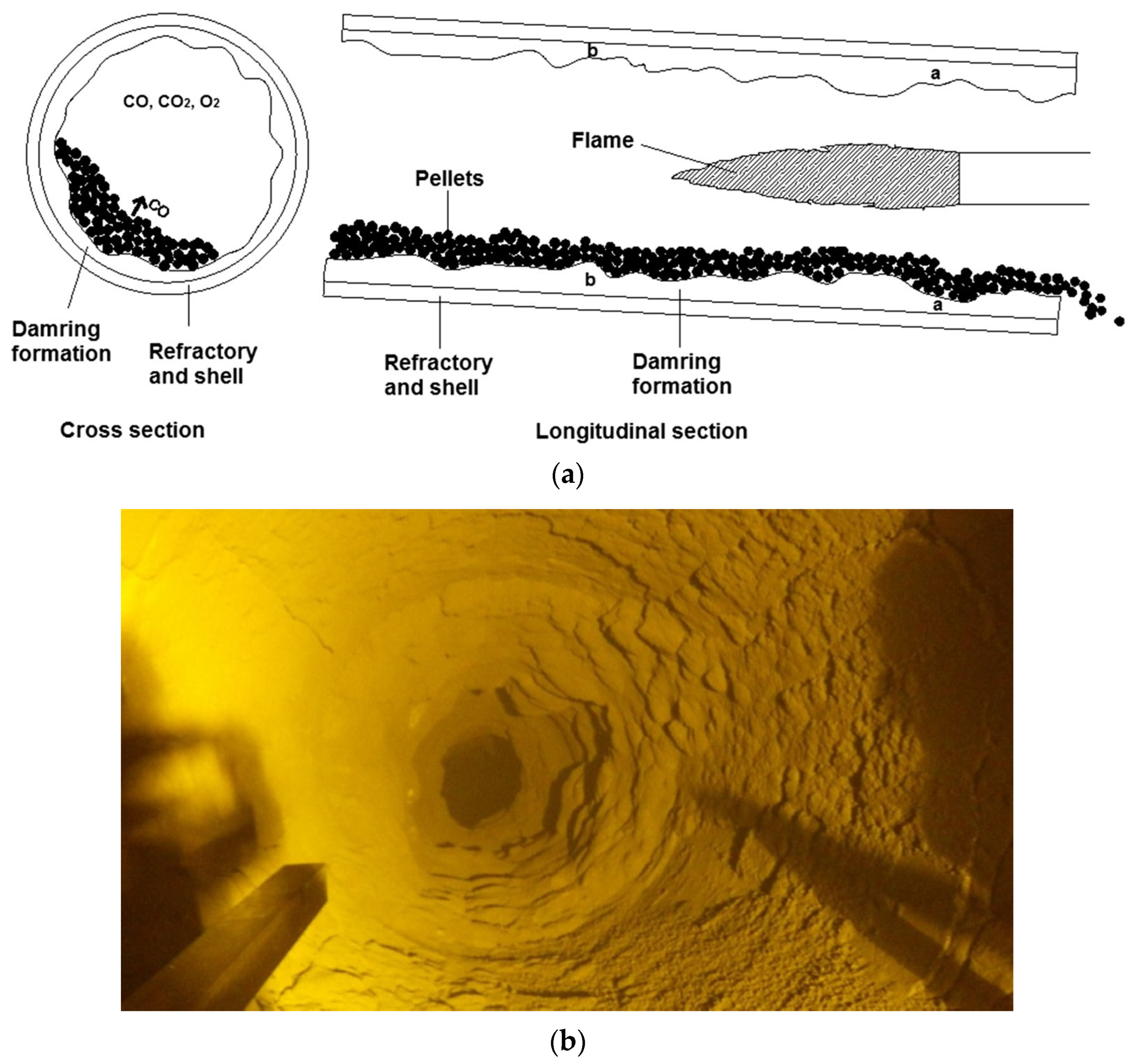
  80. van Staden, Y.; Beukes, J.P.; van Zyl, P.G.; Ringdalen, E.; Tangstad, M.; Kleynhans, E.L.; Bunt, J.R. Damring formation during rotary kiln chromite pre-reduction: Effects of pulverized carbonaceous fuel selection and partial pellet melting. Metall. Mater. Trans. B 2018, 49, 3488–3503. [Google Scholar] [CrossRef] [Green Version]
  81. Kleynhans, E.; Beukes, J.; van Zyl, P.; Fick, J. Techno-economic feasibility of a pre-oxidation process to enhance prereduction of chromite. J. S. Afr. Inst. Min. Metall. 2017, 117, 457–468. [Google Scholar] [CrossRef] [Green Version]
  82. Niemelä, P.; Krogerus, H.; Oikarinen, P. Formation, characterization and utilization of CO-gas formed in ferrochrome smelting. In Proceedings of the 12th International Ferroalloys Congress, Cape Town, South Africa, 6–9 June 2010; pp. 68–77. [Google Scholar]
  83. Zhao, B.; Hayes, P. Effects of oxidation on the microstructure and reduction of chromite pellets. In Proceedings of the INFACON XII 12th International Ferro Alloys Congress, Helsinki, Finland, 6–9 June 2010; pp. 263–273. [Google Scholar]
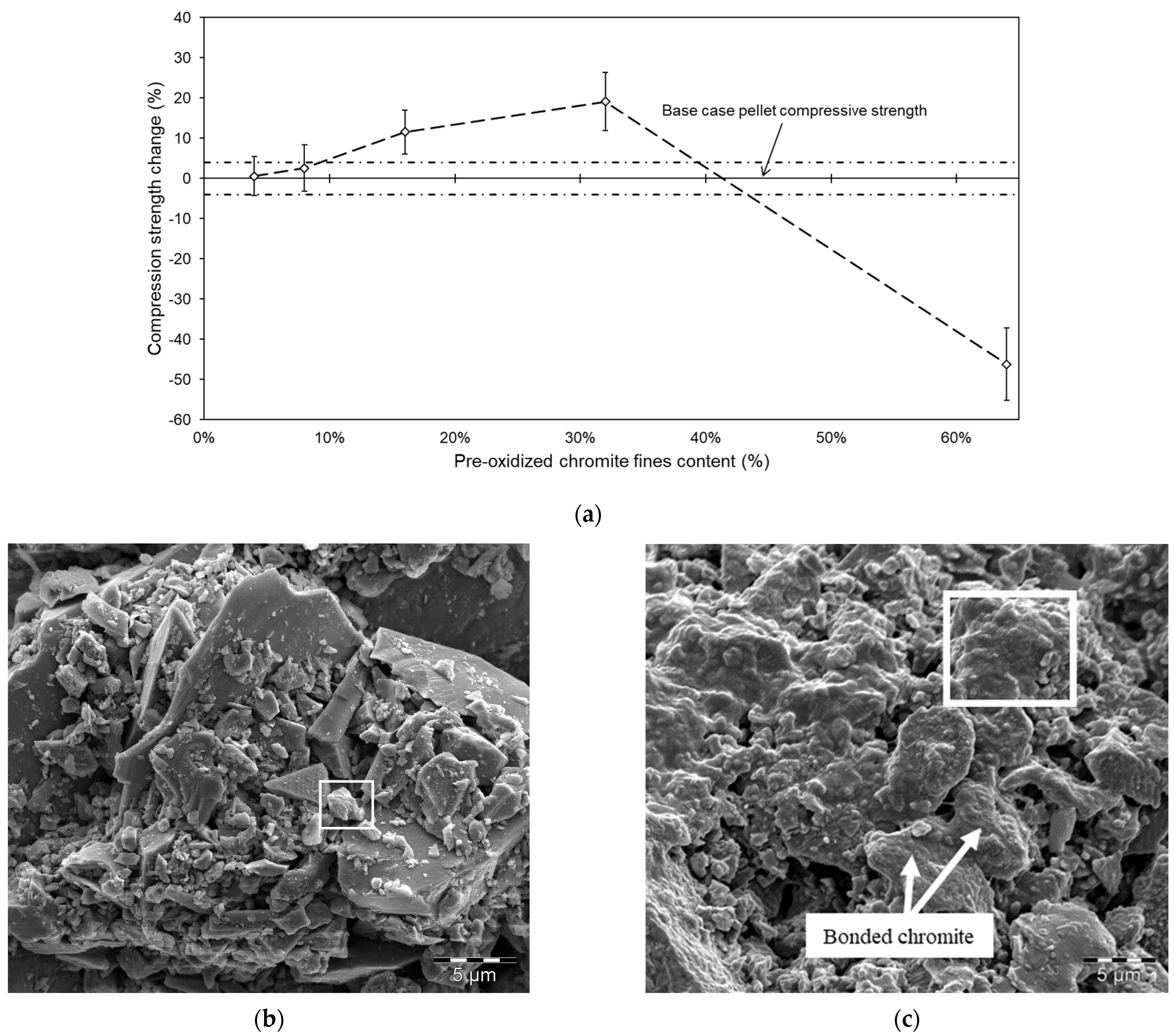
  84. Du Preez, S.P.; Beukes, J.P.; Paktunc, D.; Van Zyl, P.G.; Jordaan, A. Recycling pre-oxidized chromite fines in the oxidative sintered pellet production process. J. South. Afr. Inst. Min. Metall. 2019, 119, 207–215. [Google Scholar] [CrossRef] [Green Version]
  85. Kapure, G.; Tathavadkar, V.; Rao, C.; Rao, S.; Raju, K. Coal based direct reduction of preoxidized chromite ore at high temperature. In Proceedings of the 12th International Ferro-Alloys Congress (INFACON XII), Helsinki, Finland, 6–9 June 2010; pp. 293–301. [Google Scholar]
  86. Davies, J.; Tangstad, M.; Ringdalen, E.; Beukes, J.P.; Bessarabov, D.; du Preez, S.P. The Effect of Pre-Oxidation on the Reducibility of Chromite Using Hydrogen: A Preliminary Study. Minerals 2022, 12, 911. [Google Scholar] [CrossRef]
  87. Gericke, W.A. Environmental aspects of ferrochrome production. In Proceedings of the 7th International Ferroalloys Congress, Trondheim, Norway, 11–14 June 1995; pp. 131–140. [Google Scholar]
  88. Hesketh, H.E. Atomization and cloud behavior in venturi scrubbing. J. Air Pollut. Control Assoc. 1973, 23, 600–604. [Google Scholar] [CrossRef]
  89. Purser, D.A.; Maynard, R.L.; Wakefield, J.C. Toxicology, Survival and Health Hazards of Combustion Products; Royal Society of Chemistry: London, UK, 2015. [Google Scholar]
  90. Lind, B.B.; Fällman, A.M.; Larsson, L.B. Environmental impact of ferrochrome slag in road construction. Waste Manag. 2001, 21, 255–264. [Google Scholar] [CrossRef]
  91. Zelić, J. Properties of concrete pavements prepared with ferrochromium slag as concrete aggregate. Cem. Concr. Res. 2005, 35, 2340–2349. [Google Scholar] [CrossRef]
  92. Fares, A.I.; Sohel, K.; Al-Jabri, K.; Al-Mamun, A. Characteristics of ferrochrome slag aggregate and its uses as a green material in concrete–A review. Constr. Build. Mater. 2021, 294, 123552. [Google Scholar] [CrossRef]
  93. Karhu, M.; Talling, B.; Piotrowska, P.; Matas Adams, A.; Sengottuvelan, A.; Huttunen-Saarivirta, E.; Boccaccini, A.R.; Lintunen, P. Ferrochrome slag feasibility as a raw material in refractories: Evaluation of thermo-physical and high temperature mechanical properties. Waste Biomass Valorization 2020, 11, 7147–7157. [Google Scholar] [CrossRef]
  94. Panda, C.; Mishra, K.; Panda, K.; Nayak, B.; Nayak, B. Environmental and technical assessment of ferrochrome slag as concrete aggregate material. Constr. Build. Mater. 2013, 49, 262–271. [Google Scholar] [CrossRef]
  95. Rajashekar, K.; Reddy, C.S. An experimental study on use of ferrochrome slag aggregate in concrete making. ICI J. 2015, 15, 25–29. [Google Scholar]
  96. Al-Jabri, K.S.; Shoukry, H. Influence of nano metakaolin on thermos-physical, mechanical and microstructural properties of high-volume ferrochrome slag mortar. Constr. Build. Mater. 2018, 117, 210–221. [Google Scholar] [CrossRef]
  97. Islam, M.Z.; Sohel, K.M.; Al-Jabri, K.; Al Harthy, A. Properties of concrete with ferrochrome slag as a fine aggregate at elevated temperatures. Case Stud. Constr. Mater. 2021, 15, e00599. [Google Scholar] [CrossRef]
  98. Ojha, P.N.; Singh, A.; Singh, B.; Patel, V.; Ojha, P.; Singh, A.; Singh, B.; Patel, V. Experimental investigation on use of ferrochrome slag as an alternative to natural aggregates in concrete structures. Res. Eng. Struct. Mater. 2021, 7, 225–244. [Google Scholar] [CrossRef]
  99. Karakoç, M.B.; Türkmen, I.; Maraş, M.M.; Kantarci, F.; Demirboğa, R.; Toprak, M.U. Mechanical properties and setting time of ferrochrome slag based geopolymer paste and mortar. Constr. Build. Mater. 2014, 72, 283–292. [Google Scholar] [CrossRef]
  100. Sahu, N.; Biswas, A.; Kapure, G.U. A short review on utilization of ferrochromium slag. Miner. Process. Extr. Metall. Rev. 2016, 37, 211–219. [Google Scholar] [CrossRef]
  101. Loock, M.; Beukes, J.; Van Zyl, P. A survey of Cr(VI) contamination of surface water in the proximity of ferrochromium smelters in South Africa. Water SA 2014, 40, 709–716. [Google Scholar] [CrossRef] [Green Version]
  102. Loock-Hattingh, M.M.; Beukes, J.P.; van Zyl, P.G.; Tiedt, L.R. Cr(VI) and Conductivity as Indicators of Surface Water Pollution from Ferrochrome Production in South Africa: Four Case Studies. Metall. Mater. Trans. B 2015, 46, 2315–2325. [Google Scholar] [CrossRef]
  103. Maine, C.; Smit, J.; Giesekke, E. The Solid Stabilization of Soluble Wastes Generated in the South African Ferrochrome Industry; Water Research Commission Pretoria: Pretoria, South Africa, 2005. [Google Scholar]
  104. Bulut, V.N.; Ozdes, D.; Bekircan, O.; Gundogdu, A.; Duran, C.; Soylak, M. Carrier element-free coprecipitation (CEFC) method for the separation, preconcentration and speciation of chromium using an isatin derivative. Anal. Chim. Acta 2009, 632, 35–41. [Google Scholar] [CrossRef] [PubMed]
  105. Schubert, E.; Gottschling, R. Co-Generation: A Challenge for Furnace Off-Gas Cleaning Systems; Southern African Institute of Mining and Metallurgy: Johannesburg, South Africa, 2011; pp. 6–9. [Google Scholar]
  106. Normann, H.E. Policy networks in energy transitions: The cases of carbon capture and storage and offshore wind in Norway. Technol. Forecast. Soc. Change 2017, 118, 80–93. [Google Scholar] [CrossRef] [Green Version]
  107. du Preez, S.P.; Beukes, J.P.; van Zyl, P.G. Cr(VI) Generation During Flaring of CO-Rich Off-Gas from Closed Ferrochromium Submerged Arc Furnaces. Metall. Mater. Trans. B 2015, 46, 1002–1010. [Google Scholar] [CrossRef] [Green Version]
  108. Du Preez, S.P. Cr (VI) Generation during Flaring of Off-Gas from Closed Ferrochromium Submerged Arc Furnaces; North-West University, Potchefstroom Campus: Potchefstroom, South Africa, 2014. [Google Scholar]
  109. Molitor, B.; Richter, H.; Martin, M.E.; Jensen, R.O.; Juminaga, A.; Mihalcea, C.; Angenent, L.T. Carbon recovery by fermentation of CO-rich off gases–turning steel mills into biorefineries. Bioresour. Technol. 2016, 215, 386–396. [Google Scholar] [CrossRef] [PubMed]
  110. Dos Santos, M. Meeting the challenge of sustainability through technology development and integration in ferroalloy submerged arc furnace plant design. In Proceedings of the 12th International Ferroalloys Conference, (Infacon 12), Helsinki, Finland, 6–9 June 2010; pp. 6–9. [Google Scholar]
  111. Du Preez, S.P.; Beukes, J.P.; van Zyl, P.G.; Tangstad, M.; Tiedt, L.R. Silicon Carbide Formation Enhanced by In-Situ-Formed Silicon Nitride: An Approach to Capture Thermal Energy of CO-Rich Off-Gas Combustion. Metall. Mater. Trans. B 2018, 49, 3151–3163. [Google Scholar] [CrossRef] [Green Version]
  112. Optimal, P. 2019 Update: Eskom Tariff Increases vs. Inflation Since 1988 (with Projections to 2022). Available online: https://poweroptimal.com/2019-update-eskom-tariff-increases-vs-inflation-since-1988-with-projections-to-2022/#:~:text=From%202007%20to%202019%2C%20electricity,to%202021%20will%20be%20520%25 (accessed on 14 March 2023).
  113. Du Preez, S.; Maree, Z.; Beukes, J. Sodium Silicate Cold-Bonded Chromite Pellets for the Ferrochromium Industry–Identifying a Suitable Process. Mater. Res. 2020, 23, 1–13. [Google Scholar] [CrossRef]
  114. Zhou, Y.; Kawatra, S. Humic substance-based binder in iron ore pelletization: A review. Miner. Process. Extr. Metall. Rev. 2017, 38, 321–337. [Google Scholar] [CrossRef]
  115. Halt, J.; Kawatra, S. Review of organic binders for iron ore concentrate agglomeration. Min. Metall. Explor. 2014, 31, 73–94. [Google Scholar] [CrossRef]
  116. Srivastava, U.; Kawatra, S.K.; Eisele, T.C. Study of Organic and Inorganic Binders on Strength of Iron Oxide Pellets. Metall. Mater. Trans. B 2013, 44, 1000–1009. [Google Scholar] [CrossRef]
  117. Nelson, L.R. Evolution of the mega-scale in ferro-alloy electric furnace smelting. In Proceedings of the Minerals, Metals & Materials Society, San Diego, CA, USA, 16–20 February 2014. [Google Scholar]
  118. Halt, J.A.; Roache, S.C.; Kawatra, S.K. Cold bonding of iron ore concentrate pellets. Min. Proc. Ext. Met. Rev. 2015, 36, 192–197. [Google Scholar] [CrossRef]
  119. Lotosh, V. Steaming iron-ore pellets. Steel USSR 1973, 3, 450–452. [Google Scholar]
  120. Lotosh, V.; Efimov, A. Hardening of cement-binder pellets in a moist-air atmosphere at ordinary temperature. Steel USSR 1973, 3, 169–171. [Google Scholar]
  121. Eisele, T. A review of binders in iron ore palletization. Miner. Process. Extr. Metall. Rev. 2003, 24, 1–47. [Google Scholar] [CrossRef]
  122. Antony, M.; Tathavadkar, V.; Calvert, C.; Jha, A. The soda-ash roasting of chromite ore processing residue for the reclamation of chromium. Metall. Mater. Trans. B 2001, 32, 987–995. [Google Scholar] [CrossRef]
  123. Bessarabov, D.; Millet, P. PEM Water Electrolysis; Academic Press: London, UK, 2018; Volume 1. [Google Scholar]
  124. Bessarabov, D.; Pollet, B.G. Hydrogen (H2) Technologies in the Republic of South Africa. In Hydrogen in an International Context; River Publishers: Aalborg, Denmark, 2017; pp. 203–228. [Google Scholar]
  125. Liu, W.; Zuo, H.; Wang, J.; Xue, Q.; Ren, B.; Yang, F. The production and application of hydrogen in steel industry. Int. J. Hydrog. Energy 2021, 46, 10548–10569. [Google Scholar] [CrossRef]
  126. Bhaskar, A.; Assadi, M.; Nikpey Somehsaraei, H. Decarbonization of the iron and steel industry with direct reduction of iron ore with green hydrogen. Energies 2020, 13, 758. [Google Scholar] [CrossRef] [Green Version]
  127. Smialowski, M. Hydrogen in Steel: Effect of Hydrogen on Iron and Steel during Production, Fabrication, and Use; Elsevier: Amsterdam, The Netherlands, 2014. [Google Scholar]
  128. Astier, J.; Krug, J.; de Pressigny, Y.D.L. Technico-economic potentialities of hydrogen utilization for steel production. Int. J. Hydrog. Energy 1982, 7, 671–679. [Google Scholar] [CrossRef]
  129. Toktarova, A.; Göransson, L.; Johnsson, F. Design of clean steel production with hydrogen: Impact of electricity system composition. Energies 2021, 14, 8349. [Google Scholar] [CrossRef]
  130. Wang, R.; Zhao, Y.; Babich, A.; Senk, D.; Fan, X. Hydrogen direct reduction (H-DR) in steel industry—An overview of challenges and opportunities. J. Clean. Prod. 2021, 329, 129797. [Google Scholar] [CrossRef]
  131. Otto, A.; Robinius, M.; Grube, T.; Schiebahn, S.; Praktiknjo, A.; Stolten, D. Power-to-steel: Reducing CO2 through the integration of renewable energy and hydrogen into the German steel industry. Energies 2017, 10, 451. [Google Scholar] [CrossRef] [Green Version]
  132. Tangstad, M.; Schanche, T.; du Preez, S.P. Use of H2 in Mn-Ferroalloy Production. In Advances in Pyrometallurgy: Developing Low Carbon Pathways; Springer: Berlin/Heidelberg, Germany, 2023; pp. 35–53. [Google Scholar]
  133. Davies, J.; Tangstad, M.; Schanche, T.; du Preez, S.P. Pre-reduction of United Manganese of Kalahari Ore in CO/CO2, H2/H2O, and H2 Atmospheres. Metall. Mater. Trans. B 2023, 54, 515–535. [Google Scholar] [CrossRef]
  134. Schanche, T.L.; Tangstad, M. Prereduction of Nchwaning Ore in CO/CO2/H2 Gas Mixtures. Minerals 2021, 11, 1097. [Google Scholar] [CrossRef]
  135. Larssen, T.A.; Senk, D.; Tangstad, M. Reduction of Manganese Ores in CO-CO2 Atmospheres. Metall. Mater. Trans. B 2021, 52, 363–381. [Google Scholar] [CrossRef]
  136. Ngoy, D.; Sukhomlinov, D.; Tangstad, M. Pre-reduction Behaviour of Manganese Ores in H2 and CO Containing Gases. ISIJ Int. 2020, 60, 2325–2331. [Google Scholar] [CrossRef]
  137. Aarnæs, T.S.; Tangstad, M.; Ringdalen, E. The Influence of H2 and CO Atmospheres on SiO Formation. In REWAS 2022: Energy Technologies and CO2 Management; Springer: Berlin/Heidelberg, Germany, 2022; Volume 2, pp. 161–171. [Google Scholar]
  138. Aarnæs, T.S.; Ringdalen, E.; Tangstad, M. Use of H2 and CH4 in the Silicon Process–A Literature Review. In Proceedings of the Silicon for the Chemical & Solar Industry, Trondheim, Norway, 15–18 June 2020. [Google Scholar]
  139. Korberg, A.D.; Thellufsen, J.Z.; Skov, I.R.; Chang, M.; Paardekooper, S.; Lund, H.; Mathiesen, B.V. On the feasibility of direct hydrogen utilisation in a fossil-free Europe. Int. J. Hydrog. Energy 2023, 48, 2877–2891. [Google Scholar] [CrossRef]
  140. Öhman, A.; Karakaya, E.; Urban, F. Enabling the transition to a fossil-free steel sector: The conditions for technology transfer for hydrogen-based steelmaking in Europe. Energy Res. Soc. Sci. 2022, 84, 102384. [Google Scholar] [CrossRef]
  141. Davies, J.; Paktunc, D.; Ramos-Hernandez, J.J.; Tangstad, M.; Ringdalen, E.; Beukes, J.P.; Bessarabov, D.G.; Du Preez, S.P. The Use of Hydrogen as a Potential Reductant in the Chromite Smelting Industry. Minerals 2022, 12, 534. [Google Scholar] [CrossRef]
  142. Dishwar, R.K.; Agrawal, S.; Mandal, A.K.; Sinha, O. Smelting process of chromite ore fines to produce crude Fe–Cr–Ni–N Alloy. Trans. Indian Inst. Met. 2020, 73, 537–542. [Google Scholar] [CrossRef]
  143. Pickles, C. In-Flight Plasma Reduction of Metal Oxides. JOM 1988, 40, 31–35. [Google Scholar] [CrossRef]
  144. Sabat, K.; Rajput, P.; Paramguru, R.; Bhoi, B.; Mishra, B. Reduction of oxide minerals by hydrogen plasma: An overview. Plasma Chem. Plasma Process. 2014, 34, 1–23. [Google Scholar] [CrossRef]
  145. Alcock, C. Plasma processing of oxide systems in the temperature range 1000–3000 K. Pure Appl. Chem. 1980, 52, 1817–1827. [Google Scholar] [CrossRef] [Green Version]
  146. Dalaker, H.; Eldrup, N.; Jensen, R.; Kvande, R. Techno-economic pre-feasibility study of a hydrogen plasma-based ferromanganese plant. In REWAS 2022: Developing Tomorrow’s Technical Cycles; Springer: Berlin/Heidelberg, Germany, 2022; Volume 1, pp. 647–658. [Google Scholar]
  147. Dalaker, H.; Hovig, E.W. Hydrogen Plasma-Based Reduction of Metal Oxides. In Advances in Pyrometallurgy: Developing Low Carbon Pathways; Springer: Berlin/Heidelberg, Germany, 2023; pp. 85–94. [Google Scholar]
  148. Tathavakar, V.D.; Antony, M.; Jha, A. The physical chemistry of thermal decomposition of South African chromite minerals. Metall. Mater. Trans. B 2005, 36, 75–84. [Google Scholar] [CrossRef]
Figure 1. The extent of the BIC (shown in grey) and FeCr smelter locations (shown as red dots) [20].
Minerals 13 00809 g001
Figure 2. Simplified illustration of semi-closed (left) and closed (right) SAF/DC arc furnace designs [30]. Reprinted from Ref. [30] with permission from Elsevier (Amsterdam, The Netherlands).
Minerals 13 00809 g002
Figure 3. A generalized flow diagram indicating the most common process steps utilized by FeCr producers (adapted by [30] from [14,23]). Reprinted from Ref. [30] with permission from Elsevier (Amsterdam, The Netherlands).
Minerals 13 00809 g003
Figure 4. Run-of-mine (ROM) chromite beneficiation process to produce typical metallurgical-grade chromite concentrate [10]. Reprinted from Reference [10] with permission from Elsevier.
Minerals 13 00809 g004
Figure 5. A flow diagram of the process steps used during green pellet generation, intended for pre-reduction (red) or oxidative sintering (blue) curing. Common process steps are indicated in black. Reproduced from Reference [20].
Minerals 13 00809 g005
Figure 6. A generalized flow diagram of the pre-reduction (red) and oxidative sintering (blue) processes, and furnace feed material screening destined for semi-closed (indicated in yellow) and closed (indicated in purple) SAF smelting. Common process steps are indicated in black. Reproduced from Reference [20].
Minerals 13 00809 g006
Figure 7. Illustration of the cross and longitudinal sections of a rotary kiln used in pelletized chromite pre-reduction (a) and an example of damring build-up inside a pelletized chromite pre-reduction kiln (b) [80]. Reproduced from Reference [80] with permission from Springer under Creative Commons Attribution 4.0 International License http://creativecommons.org/licenses/by/4.0/ (accessed on 2 May 2023).
Minerals 13 00809 g007
Figure 8. Compressive strength of undersized particulate material (also referred to as pre-oxidized chromite fines) containing pellets (a), and micrographs of aluminosilicate-type particles (white boxes) before (b) and after (c) pre-oxidative curing [84]. Preproduced from Reference [84] with permission from ScieELO South Africa under Creative Commons Attribution 4.0 International License http://creativecommons.org/licenses/by/4.0/ (accessed on 2 May 2023).
Minerals 13 00809 g008
Figure 9. A flow diagram of currently applied chromite smelting processes and corresponding off-gas, FeCr, and slag handling procedures. Reproduced from Reference [20].
Minerals 13 00809 g009
Figure 10. Schematic illustration to demonstrate the functioning of off-gas venturi scrubbing. Reproduced from Reference [20].
Minerals 13 00809 g010
Figure 11. Schematic illustration showing the process flow of BFD collection and Cr(VI) treatment [78]. Reproduced from Reference [78] with permission from Water SA under Creative Commons Attribution 4.0 International License http://creativecommons.org/licenses/by/4.0/ (accessed on 2 May 2023).
Minerals 13 00809 g011
Figure 12. Leachable Cr(VI) content as a function of leaching solution pH, combined water soluble and sparingly water-soluble Cr(VI), and total Cr(VI) of investigated BFD. Presented data were normalized to % Cr(VI) based on the total extractable Cr(VI) content [78]. Reproduced from Reference [78] with permission from Water SA under Creative Commons Attribution 4.0 International License http://creativecommons.org/licenses/by/4.0/ (accessed on 2 May 2023).
Minerals 13 00809 g012
Figure 13. A typical off-gas flare on top of a closed SAF stack [107,108]. Reproduced from Reference [107] with permission from Springer under Creative Commons Attribution 4.0 International License http://creativecommons.org/licenses/by/4.0/ (accessed on 2 May 2023).
Minerals 13 00809 g013
Figure 14. A surface (a) and cross-sectioned (b) micrograph of SiC particles prepared by the carbothermic treatment of undersized quartz and carbonaceous reductant classified as waste materials by a South African FeCr producer [111]. Reproduced from Reference [111] with permission from Springer under Creative Commons Attribution 4.0 International License http://creativecommons.org/licenses/by/4.0/ (accessed on 2 May 2023).
Minerals 13 00809 g014
Figure 15. The average compressive strength of 3 wt% sodium silicate—3 wt% SiO2—1, 2, 4, 6 M KOH pellets cured at 75 °C. The reference (shown by a solid red line) represents 32-day air-dried pellets bonded with 3 wt% sodium silicate and water as the moisture source. The standard deviation of the reference is shown by the dashed red lines. The solid green line represents the strength of pre-reduced pellets obtained from a South African FeCr producer [113]. Adapted from Reference [113] with permission form SciELO Brazil under Creative Commons Attribution 4.0 International License http://creativecommons.org/licenses/by/4.0/ (accessed on 2 May 2023).
Minerals 13 00809 g015
Figure 16. An Ellingham diagram showing the standard ∆G (Gibbs free energy) of the reduction of metal oxides with solid CO and H2 (constructed with HSC9 thermo-chemical software).
Minerals 13 00809 g016
Figure 17. A phase stability diagram for a (Cr, Fe)-H2-H2O system as a function of partial pressures of hydrogen and water vapor at 1000 °C. Equilibrium lines associated with Cr and Fe are indicated in blue and red, respectively [141]. Reproduced from Reference [141] with permission from MDPI AG under Creative Commons Attribution 4.0 International License http://creativecommons.org/licenses/by/4.0/ (accessed on 2 May 2023).
Minerals 13 00809 g017
Table 1. The average Cr2O3 content and Cr/Fe ratio of chromite ores from various countries [12,13].
Origin CountryCr2O3 %Cr/Fe Ratio
South Africa (metallurgical grade)441.5
South Africa (UG2)411.3
Kazakhstan483.5
India442.7
Zimbabwe443.0
Turkey413.0
Table 2. Main commercial grades of FeCr according to ISO-standard 54481-81 [24,29].
FeCr Grade% Cr% C% Si% P% S
High-carbon45–704–100–10<0.05<0.10
Medium-carbon55–750.5–4<1.5<0.05<0.05
Low-carbon55–950.1–0.5<1.5<0.03<0.03
Charge-grade53–585–83–6
Table 3. Different high carbon FeCr process route comparisons [51].
Furnace TypeCr Recovery (%)SEC
(kWh·t−1)
EoS (Single Furnace Maximum Size/Single Furnace Output)
Semi-closed SAF (no raw material screening)70–75430030 MVA/50 ktpa #
Closed SAF (oxidative sintered feed and pre-heating)83–883200135 MVA/240 ktpa
Closed SAF (pre-reduced pelletized feed)88–922400 *66 MVA/160 ktpa
Closed DC arc furnace88–92420060 MVA/110 ktpa
# indicate EoS as 30 MVA; 45 MVA furnaces are in routine operation in South Africa [18]. * Excluding energy used during pre-reduction.
Disclaimer/Publisher’s Note: The statements, opinions and data contained in all publications are solely those of the individual author(s) and contributor(s) and not of MDPI and/or the editor(s). MDPI and/or the editor(s) disclaim responsibility for any injury to people or property resulting from any ideas, methods, instructions or products referred to in the content.

