1. Introduction
China is one of the major global producers of iron and steel, and large amounts of carbon dioxide (CO
2) and steel slag are emitted in the manufacture of iron and steel. In 2021, China’s emissions from the energy and industry exceeded 11.9 billion tons, accounting for 33% of the global total. According to the National Bureau of National Statistics, the output of crude steel in China reached 1.03 billion tons in 2021, accounting for 52.8% of the world’s total production. The mass of steel slag accounts for 10%–15% of crude steel mass. In recent years, with urban infrastructure construction and development, the demand for sand and stone aggregates has further increased, and the output of natural sand and stone showed a trend of short supply, thus requiring the processing and manufacturing of artificial aggregate with the same strength as natural sand and stone to meet the production requirements. Further comprehensive utilization of steel slag, improvements in the effective utilization rate of steel slag, and the production of green, safe, environmentally friendly, and highly valuable steel slag products have substantial environmental benefits and economic benefits and are worth further exploration [
1,
2].
As a challenge, the solid waste produced in steelmaking increases yearly, and the environmental problem caused by CO
2 has become much more serious recently. The rationality of utilizing steel slag and CO
2 together is increasing. Steel slag has high carbonization reactivity, reacts with CO
2, and applies carbonation technology. The solid storage of CO
2 in the form of mineral absorption may absorb a large amount of CO
2 [
3]. This method has the advantages of thermodynamic feasibility, high reactivity, and strong fixing ability. Carbonating steel slag activates the RO phase inside [
4], improves its mechanical properties and volume stability [
5], and plays a positive role in the practical application of carbonated steel slag [
6,
7]. Yu, J., et al. [
8] studied CO
2 capture in steel slag and proved that its carbonization reaction is controlled by reaction kinetics, as well as the diffusion of gaseous CO
2, and steel slag can capture and permanently store CO
2. Tian, S.C. et al. [
9] studied direct gas–solid carbonization under different working conditions to determine the storage of CO
2 and found that temperature is an important factor affecting the reaction rate and carbonation conversion rate of steel slag.
Steel slag can be used for various purposes in practical applications, including fine and coarse aggregates for concrete in the construction industry, asphalt pavement materials for highways, and filling materials for various products. Steel slag can also be used as coarse or fine aggregates for concrete, and concrete containing steel slag aggregate exhibits satisfactory compressive and flexural strength [
10,
11,
12]. A scholar [
13] achieved the balance between the hydration activity and volume stability of steel slag by adjusting the accelerated precarbonization conditions, and proved the volume stability of steel slag depends largely on the time of accelerated precarbonization. Pang, B., et al. [
14] studied the carbonized steel slag particles used to replace limestone, quartz, and other common natural aggregates to detect the strength of concrete test blocks. The free CaO content of steel slag was reduced from 7% to less than 1% in 3 h after carbonization treatment, and the compressive strength of concrete was increased by 20% in 28 days, which showed the feasibility of carbonized steel slag as an aggregate. Ghouleh, Z., et al. [
15] produced artificial aggregates and proved CO
2 can be utilized to prime waste steel slag for use as an aggregate in concrete.
However, limited studies have focused on the mass production of the direct carbonation of steel slag as an aggregate additive to building materials, the factors limiting the carbonation and solidification conditions of aggregate are not clear, and product characteristics have not been studied. Therefore, based on the coupling reaction between steel slag and carbon dioxide, this paper studied the influence of the increase in carbonation and solidification time on the carbonation degree of steel slag materials. It also determined the maximum CO2 storage rate under the most suitable conditions mainly to absorb a large amount of CO2 in order to reduce steel slag damage to the environment and CO2 pollution in the atmosphere. At the same time, according to the relevant standards, the mechanical properties and stability of carbonized steel slag were tested to determine whether carbonized steel slag can be widely used as an aggregate in the field of building materials.
2. Materials and Methods
2.1. Experimental Materials
The material used in the experiment was steel slag. The main chemical composition, bulk mineral composition, and particle number of the raw material were analyzed using an X-ray fluorescence spectrometer (XRF) and a mineral dissociation analyzer (MLA), and the results are shown in
Table 1. In steel slag, the chemical composition of CaO is the highest, followed by Fe
2O
3, with a small amount of SiO
2, MgO, and Al
2O
3. The content of basic metal oxide represented by CaO and MgO is more than 45.41%. In the mineral phase, the content of calcium ferrite mineral composition is the highest, accounting for 23.13%, and the number of particles is 9240, followed by calcium silicate mineral, accounting for 21.78%. Calcium oxide, magnesium oxide, and other minerals are also present. Among them, calcium silicate, calcium oxide, magnesium oxide, and calcium iron garnet can react with CO
2 gas, proving that the original steel slag contains active components to fix the CO
2 gas, and solidify the gas with the form of stable carbonate in mineral systems.
The main drugs and equipment used in the experiment were phenolphthalein (Guangdong Yunxing Biotechnology Co., Ltd.) (Shaoguan, China), CO2 gas (Beijing Millennium Capital Gas Co., Ltd.) (Beijing, China), electronic scale, 500 mL volumetric bottle, boiling box, autoclaved kettle (YZF-2S), length ratio instrument, concrete carbonation test box, electric blast drying oven, vibrating standard sieve machine, cement pulp mixer, microcomputer-controlled pressure testing machine, standard constant temperature, and humidity curing box.
2.2. Experimental Methods
First, nine particle materials with a size of at least 20–30 mm were obtained. The particle surface was brushed clean in the ascending order of particle size into the carbonized curing box. The curing box temperature was 25 °C, relative humidity was 75%, and CO2 concentration was 20%. Under this condition, curing was performed for 6 h, 12 h, 18 h, 24 h, and 3 days successively. After reaching the curing time of carbonization, a corresponding material was obtained and cut with a grinding wheel, the surface was wiped clean, and a phenolic phthalein indicator was sprayed to test carbonization depth.
Mineralization was carried out under a temperature of 25 °C, relative humidity of 75%, a CO2 concentration of 20%, and a carbonization period of 6, 12, 18, and 24 h. Then, enough steel slag particles with a diameter of 0.6–2.36 mm were placed in a curing box for carbonization curing at 6, 12, 18, and 24 h, denoted as S1–S4, and uncarbonized steel slag samples were denoted as S0.
2.3. Research Methods
2.3.1. Carbonization Rate
The 1% phenolphthalein indicator was sprayed on the cut surface of carbonized particles. After spraying, the color of the carbonized part did not change, while the non-carbonized part turned purple red. When the boundary between the carbonized part and the non-carbonized part became obvious, a vernier caliper was used to measure the vertical distance between the intersection boundary of the carbonized part and the non-carbonized part to the aggregate surface. The values were measured at least thrice, the average value was calculated, and the data were recorded.
2.3.2. CO2 Retention Rate
The total carbon of steel slag was tested using a carbon–sulfur analyzer (Ncs Testing Technology Co., Ltd., CS-2800, Beijing, China) the mass of steel slag was weighted before and after carbonization, and the total carbon in the steel slag before and after carbonization (
C) was calculated. The carbon dioxide content
(C0) was calculated using Equation (1), as follows:
The CO
2 retention rate (
R) of the steel slag was calculated using Equation (2):
where
G is the mass of steel slag before carbonization;
2.3.3. Stability Performance Test
The process was based on the Test Method for Stability of Steel Slag (GB/T 24175-2009). A certain quality of steel slag with a particle size of 4.75–2.36 mm was weighed, rinsed with water to remove floating dust and impurities on the surface, completely wet, placed in a pressure autoclast under 2.0 MPa saturated steam pressure for 3 h, and dried to a constant weight. The mass, , was recorded. The dried steel slag was passed through a 1.18 mm sieve and placed on a vibrating sieve machine for 20 min of vibration. The screen mass, , was determined, and the autoclave chalked ratio was calculated.
2.3.4. Mechanical Property Test
The apparent density test was based on Sand for Construction (GB/T 14684-2011). First, 300 g of steel slag sample was placed in a volumetric bottle. Water was added to the scale line of 500 mL. The volumetric bottle was rotated and shaken. The cap was tightly plugged, the bottle was allowed to stand for 24 h, and the mass was determined. Then, the water and the sample were poured out, the volumetric bottle was washed, water was poured into the volumetric bottle to the 500 mL scale, the bottle was tightly plugged, the mass was determined, and the apparent density was calculated.
The soundness test was based on Sand for Construction (GB/T 14684-2011). First, 330 g of single-grade steel slag sample was poured into the assembled compression steel die, and placed on the press support plate at a speed of 500 N per second loading, to 25 kN stable load 5 s, unloading at the same speed. Then, the steel slag sample was poured out, and the lower limit screen for screening was used. The sieve allowance was weighed, the amount was passed through, and the crushing index value was calculated.
2.3.5. Mineral Phase Change Test
XRF (PANalytical B.V., Axios MAX, China) and MLA (FEI, FEI MLA 250, Hillsboro, OR, USA) were used to analyze the main chemical composition, bulk mineral composition, and particle number of raw materials. An X-ray diffractometer (XRD) (Rigaku, UltimaIV, Tokyo, Japan) was used to analyze the mineral phase changes of each group of carbonized materials. A Fourier infrared spectrometer (FTIR) (NICOLET, iS10, USA) was used to analyze the changes in the molecular chemical structure and chemical bond inside the aggregate. A thermogravimetric analyzer (TG) (TA Instruments, TGA Q500, USA) was used to obtain the pyrolysis mass loss and data, infer the material composition, and measure the degree of carbonization macroscopically. A scanning electron microscope (Hitachi, S-3400N, Tokyo, Japan) was used to observe the microstructure of the steel slag aggregate before and after carbonization, and the structure was analyzed. EDS (EDAX, Appllo X, USA) was used to analyze the type and content of microcomponent elements.
3. Results
3.1. Carbonization Rate
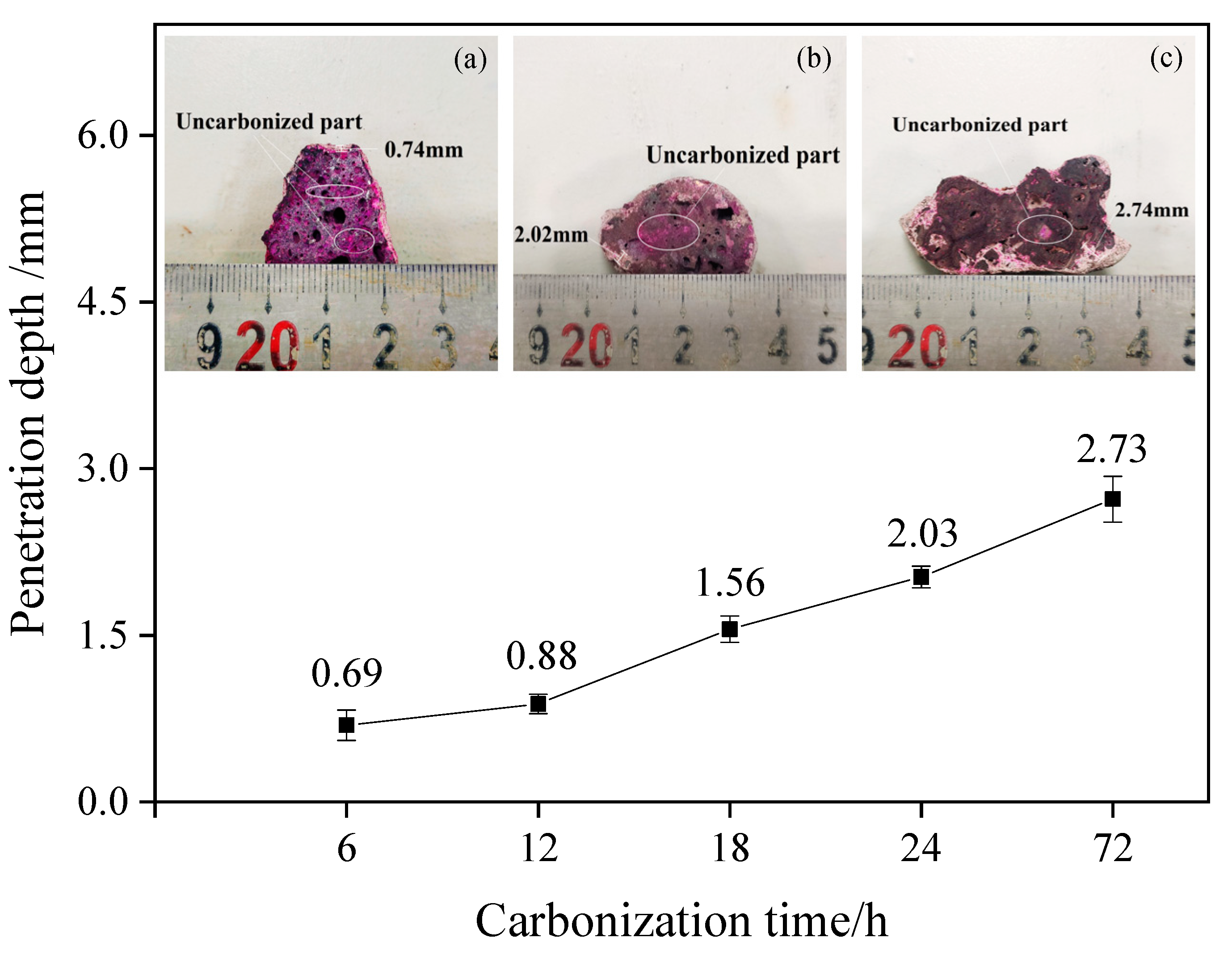
Particles with a diameter of 20–30 mm after carbonization were obtained, cut in the appropriate position, and sprayed with a phenolphthalein indicator. The discoloration of the section surface was observed.
Figure 1 shows the specific discoloration and the measurement results of the depth of carbonization. Excluding dense particles and individual differences, the experimental results clearly show that the increase in carbonization time plays a positive role in increasing the carbonization depth inside the test block. With the gradual increase in carbonation time, the particle carbonation depth gradually increased from 0.69 mm to 2.73 mm, and with the increase in carbonation time and the deepening trend, the effect was improved.
3.2. CO2 Retention Rate
Mineralization was carried out under a temperature of 25 °C, relative humidity of 75%, and a CO
2 concentration of 20% for the carbonized curing of materials with different grain grades. The relationship between retention rate and carbonization time among different grain-size materials is shown in
Figure 2. According to the curve change, the adsorption capacity of the fine-grained material (0.6–2.36 mm) is better than that of the coarse-grained material (2.36–4.75 mm). The carbonation effect of the particles with a size range of 0.6–2.36 mm can reach 9.40% after 24 h of carbonation treatment, and a 1.51% carbonization effect can be achieved for particles with a size range of 2.36–4.75 mm.
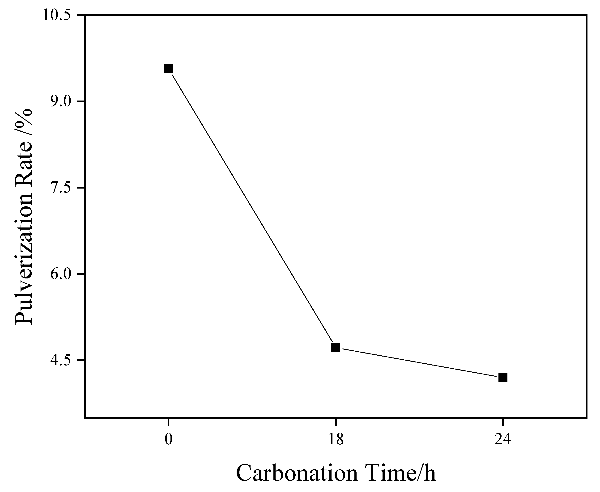
3.3. Pressure Vaporization Rate
Figure 3 shows the pressure vaporization rate results of coarse-grained material (4.75–2.36 mm). The test results show that the pressure vaporization rate of steel slag aggregate (4.75–2.36 mm) decreased from 9.57% to 4.72% and 4.20% after carbonization curing for 18 and 24 h, respectively. The basic oxides in the structure, such as magnesium oxide and calcium oxide, can effectively absorb the CO
2 gas around the system and generate stable carbonate to improve the stability. Moreover, with an increase in the carbonization curing time, the pulverization rate of steel slag particles displayed a downward trend under a saturated steam pressure of 2.0 MPa, indicating that the stability of steel slag particles was substantially enhanced.
3.4. Mechanical Property Test
Table 2 shows the apparent density and firmness of samples S3 and S4 after carbonization curing. The test results show that after 18 and 24 h of carbonization curing, the apparent density and firmness of the steel slag meet the class II standard in GB/T 14684. The longer the carbonization time is, the better the soundness of the material is.
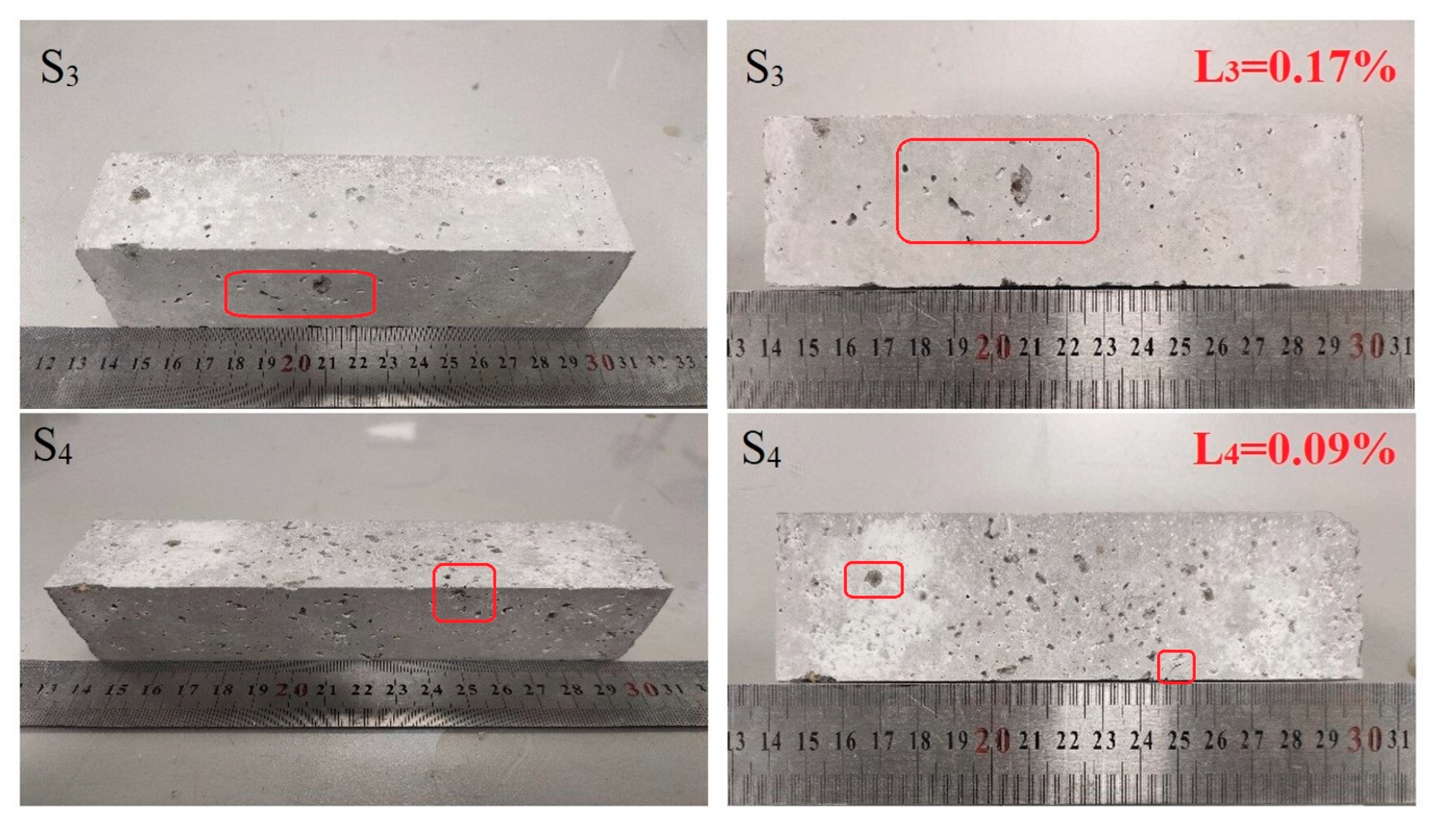
Figure 4 shows the stability test results of materials carbonized for 18 and 24 h under a pressure of 0.5 MPa and a treatment time of 1.5 h. The test results show slight local pitting and spalling phenomena on the surface of the specimen, but the whole specimen is intact. Under a pressure of 0.5 MPa and a treatment time of 1.5 h, the autoclave method for soundness increased with an increase in the carbonation curing time, and the volume stability increased. Considering the presence of f-CaO and f-MgO components in steel slag, Ca(OH)
2 and Mg(OH)
2 were gradually generated in the hydration reaction, resulting in the volume change of the block before and after the reaction and then local pitting and cracks on the surface of the specimen.
3.5. Mineral Phase Change
3.5.1. Microscopic Analysis of Mineral Composition
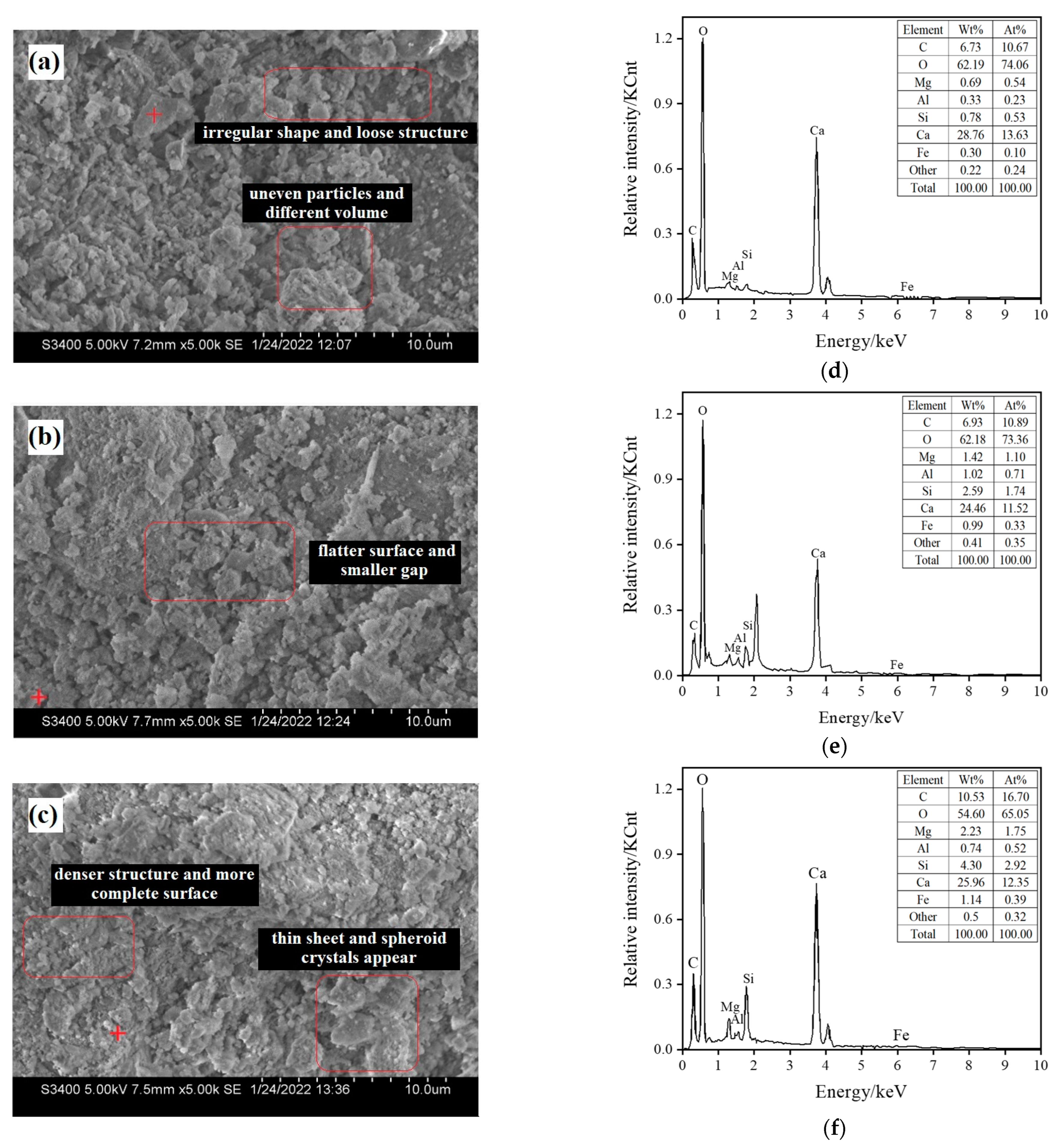
Figure 5 shows steel slag particles with a size of 0.6–2.36 mm and the scanning electron microscopy (SEM) images of three groups of materials cured by different carbonization times, labeled raw ore S
0 (not carbonized), S
3 (carbonized for 18 h), and S
4 (carbonization for 24 h).
Figure 5a shows that the surface of the particles is uneven, the volume is different, the shape is irregular, and the structure is loose. After carbonization for 18 h, lamellar crystals appeared on the surface of the particles, as shown in
Figure 5b; the flatter the surface is, the smaller the gap is. After 24 h carbonization and curing, as shown in
Figure 5c, relatively complete crystals appeared, and void holes were reduced. The surface of mineral particles is a flat and thin sheet, spheroid crystals appear, the structure is dense, and the surface is complete.
3.5.2. Test Results of Microscopic Changes in Mineral Phases
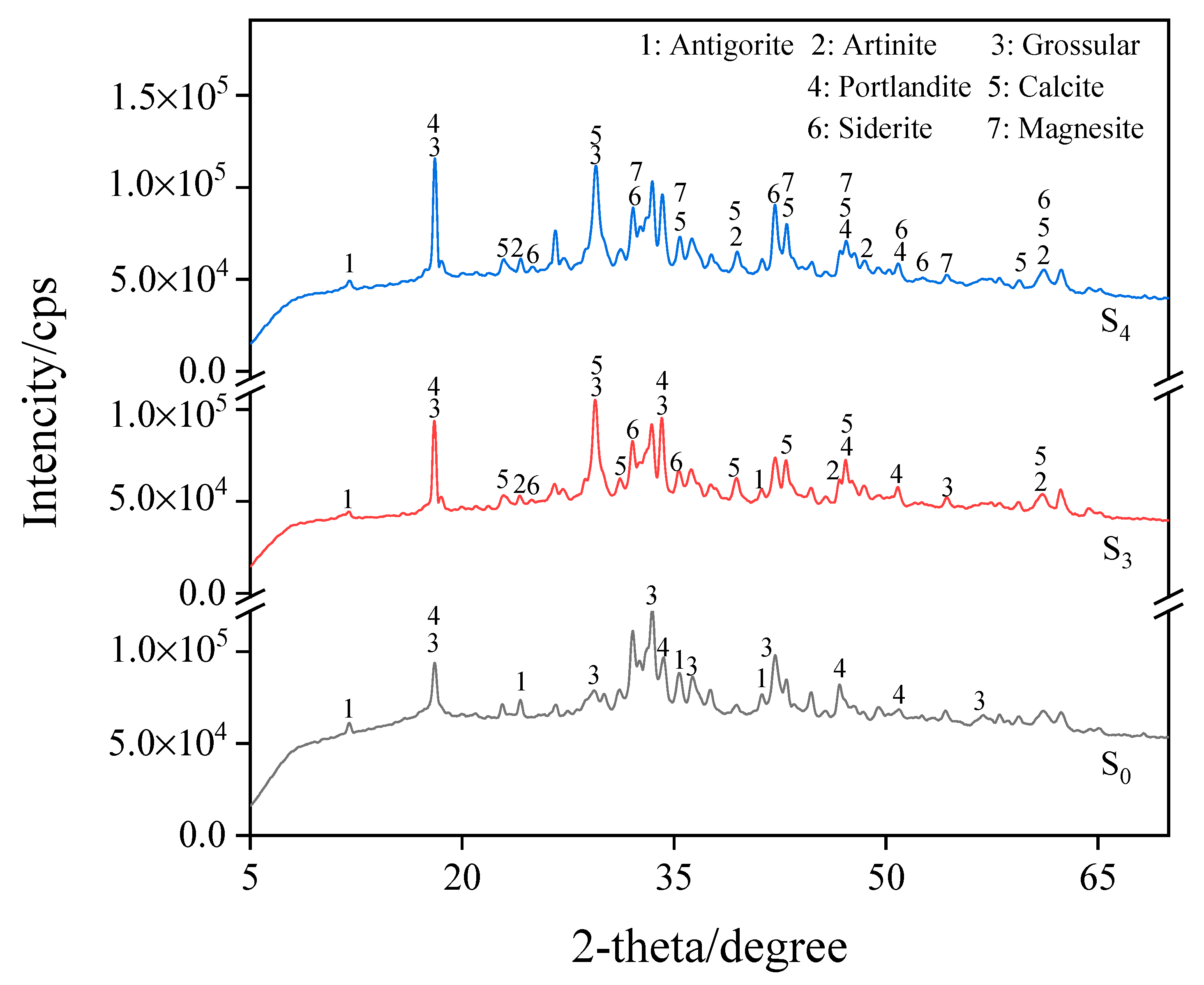
Figure 6 shows steel slag particles with a size of 0.6–2.36 mm and the XRD pattern of three groups of materials cured under different carbonization times, labeled raw ore S
0 (not carbonized), S
3 (carbonized for 18 h), and S
4 (carbonization for 24 h). The XRD pattern shows that the undisturbed steel slag contains more silicate minerals when it has not been carbonated. At a temperature of 25 °C, relative humidity of 75%, and a CO
2 concentration of 20%, after carbonation curing, the CaO in the sample particles and the calcium-rich mineral components react, the calcium mineral phase diffraction peak decreased, calcium carbonate diffraction peak appeared, and a calcium carbonate substance was generated (CaCO
3, PDF-#05-0586). The calcium ferrite groups emerged progressively, predominantly in the form of siderite (FeCO
3, PDF-#08-0133). After 24 h of carbonization curing, the particle components absorbed CO
2 and generated carbonate substances, resulting in the appearance of magnesium carbonate products, such as artinite (Mg
2CO
3(OH)
2 • 3H
2O, PDF-#06-0484) and magnesite(MgCO
3, PDF-#08-0479). This process resulted in CO
2 absorption and improved the strength of granular materials.
- 2.
TG-DTG analysis
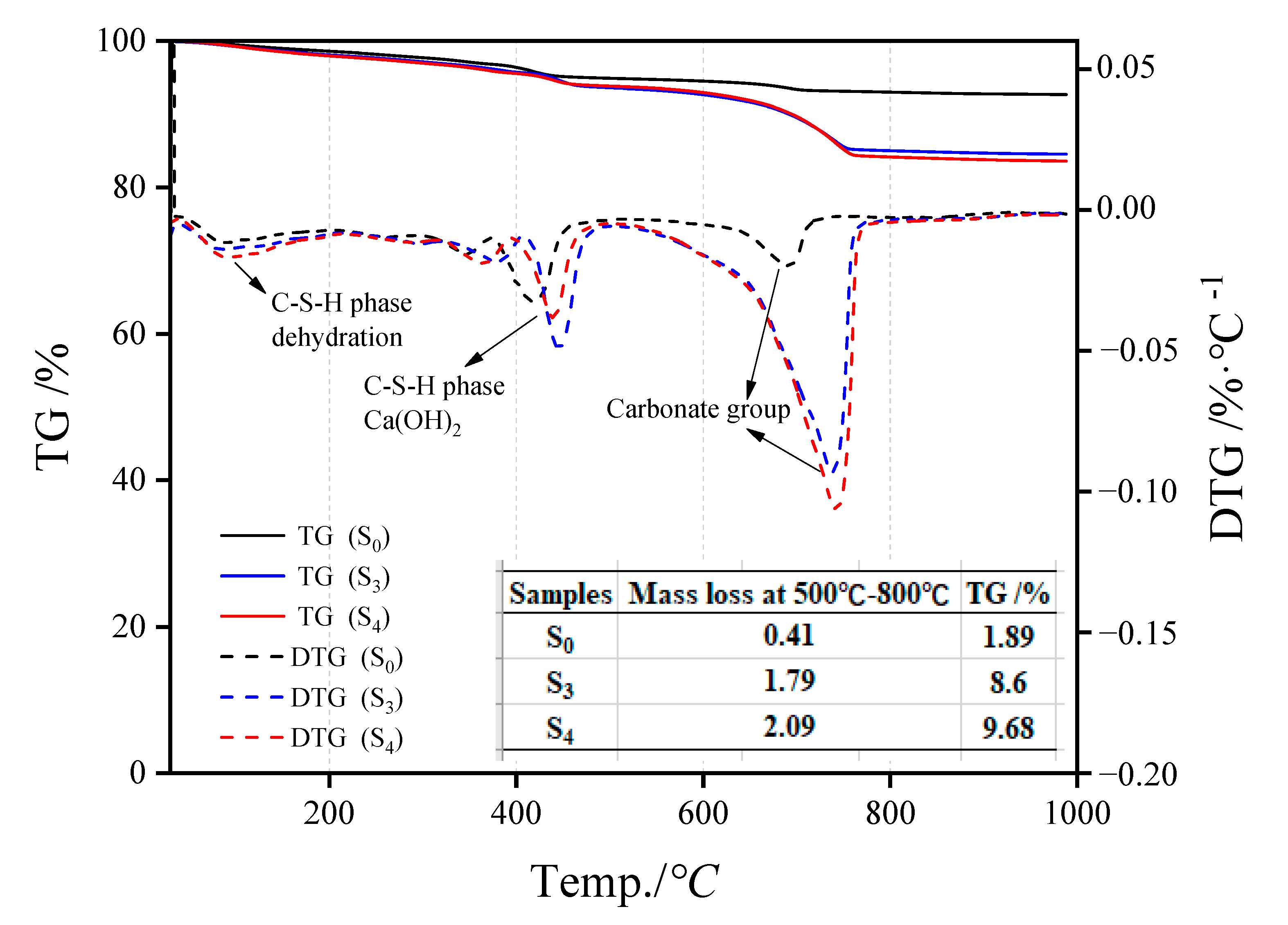
Figure 7 represents the S
0, S
3, and S
4 TG-DTG analysis results. The mass difference of 50 °C–350 °C is caused by the evaporation of interlayer water in the C-S-H structure [
16], while that at 200 °C–500 °C is due to the loss of a hydroxyl group in the product structure [
17], and that between 500 °C–800 °C is mainly related to carbonate materials [
18,
19]. The endothermic peaks of dehydration and decomposition of carbonate materials in the C-S-H structure of uncarbonized steel slag are considerably smaller than those in the hydroxyl structure, indicating the presence of a certain amount of hydration products in the slag, but the amount is small. After carbonation curing, the peaks of the three substances in steel slag aggregate changed substantially. The peaks in the range of 500 °C–800 °C changed the most, indicating that the carbonate products showed an increasing trend, and the increment was CO
2 absorption. The carbon contents in S
0, S
3, and S
4 were 1.89%, 8.60%, and 9.68%, respectively.
- 3.
FTIR analysis
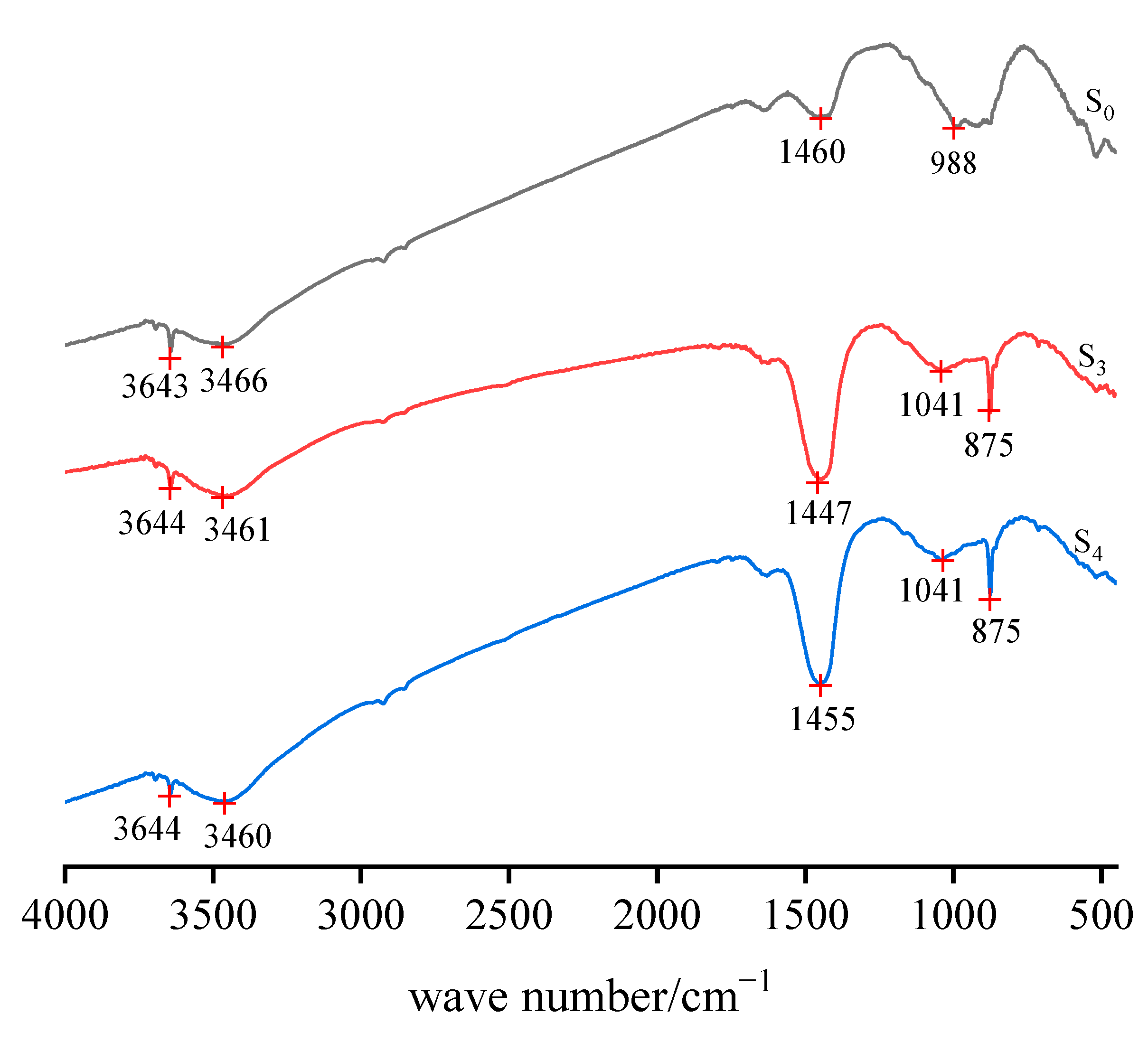
Figure 8 shows the S
0, S
3, and S
4 infrared absorption spectra of the sample. The relative strength of the infrared absorption peak reflects the content of the group. The greater the peak strength of a position in the figure is, the higher the content of the group in the position is. The absorption band at 3460–3644 cm
−1 represents the O–H stretching vibration band belonging to the water molecule products of hydration in the steel slag structure. The samples carbonized for 18 h (S
3) and 24 h (S
4) showed carbonic acid–base groups, and the absorption vibration peaks were observed at 1455, 1447, and 875.28 cm
−1. The increase in the relative strength of the absorption vibration peak of the carbonate base group can reflect the increase in its content, which proved the formation of carbonate substances, and the quality of carbonated products increased with an extension of the carbonization time. Moreover, the absorption and vibration peak of the Si–O group was 988 cm
−1. The results agree with the XRD and TG-DTG analysis.
4. Discussion
In this investigation, the coupling mineralization reaction between carbon dioxide and steel slag was used to store carbon dioxide in steel slag, while the active calcium oxide and magnesium oxide in steel slag were converted into carbonate. The results show that with the increase in the reaction time, more carbonated products were generated, and the physical properties were improved. This method can transform steel slag into fine building aggregate.
The carbonization experimental results clearly show that the increase in the carbonization time played a positive role in increasing the carbonization depth inside the test block. Based on the analysis of the carbonation depth of mortar made from steel slag powder, with the increase in the carbonation time and the deepening trend, the effect was improved [
20]. Therefore, time is an important factor for carbonation. Excluding dense particles, individual differences, and other factors, fine-grained materials such as sand (<4.75 mm) require 6–24 h for carbonization. Gravel (>4.75 mm) and other coarse-grained materials need more than 24 h. At the beginning of the reaction, the reaction time was short, the carbonization depth was shallow, and the rate was fast. In the later stage of the reaction, the carbonization depth deepened, but the rate decreased slightly as the reaction progressed. This finding was obtained possibly because the carbonization products generated by the reaction increased and blocked part of the pores, so that the gas in the later stage could not enter deeper into the particles, which reduced the reaction rate and the production of carbonate materials.
The carbonation effect of 0.6–2.36 mm particles reached 9.40% after 24 h of carbonation treatment, while that of particles with a size range of 2.36–4.75 mm reached 1.51%. Considering the greater activity of fine particles than coarser ones, the experimental results indicate that the smaller the particle size of the steel slag is, the higher the carbon fixation rate is. This result is consistent with the results obtained in a study by Huijgen, W. [
21] on the carbonization behavior of steel slag in water suspension. Based on the results of carbonization curing, steel slag particles of different grades can absorb CO
2 at different degrees, and with the growth in the carbonation curing time, the CO
2 of steel slag aggregate particles’ retention rate also increases, which can effectively retain CO
2 to seal CO
2 gas in steel slag.
The concentration of carbon dioxide gas utilized in this experiment reached 20%, which is comparable to the flue gas concentration found in actual industrial production. Therefore, if effectively optimized under current conditions, steel slag can serve as a novel medium for flue gas recovery that not only absorbs discharged carbon dioxide into the atmosphere but also functions as an effective aggregate. Meanwhile, the practical implementation is uncomplicated, that is, by simply co-locating carbon dioxide flue gas and reaction waste steel slag within a single reactor, the application can easily be achieved without any superfluous or complex procedures. Based on the existing research, further investigation is required to improve the firmness and stability of excessively small particles, and the key factors and laws affecting the carbonization reaction rate of main calcium-bearing mineral phase and free phase in steel slag need to be investigated. The carbonization rate of steel slag also needs to be thoroughly investigated under the coupling effect of multiple factors, such as particle size, CO2 concentration, pressure, and relative humidity, to optimize the process parameters, improve carbonization efficiency, and reduce costs. At the same time, the relationship between the carbonization degree of steel slag and its stability and how to determine the safe residual amount of uncarbonized free CaO and MgO in steel slag remains to be further studied.
5. Conclusions
By using the coupling mineralization reaction between steel slag and carbon dioxide, active calcium oxide and magnesium oxide in steel slag can be converted into stable carbonate by absorbing carbon dioxide and retaining gas. To a certain extent, it can reduce the content of carbon dioxide gas and absorb substantial amounts of steel slag to alleviate the accumulation of land and achieve a reasonable and effective production of building materials aggregate for the purpose of comprehensive utilization.
When 0.6–2.36 mm grade materials were carbonized and cured, with an increase in the carbonization time, the CO2 storage of steel slag particles increased, the content of carbonate substances generated increased, and particle soundness and stability were improved. This finding helped in overcoming the reuse problem caused by the instability of steel slag. After 18 h of carbonization curing, the autoclave chalked ratio of steel slag aggregate reached 4.72%, and the apparent density and firmness of carbonized steel slag material (1.18–2.36 mm) as an aggregate met the standards. After 24 h of carbonization curing, the autoclave chalked ratio of steel slag aggregate decreased from 9.57% to 4.2%. Moreover, the apparent density and firmness of carbonized steel slag material (0.6–2.36 mm) as an aggregate also met the standards. The CO2 absorption and carbonization curing time of this kind of steel slag show the same increasing trend; the longer the time is, the greater the absorption amount is. Carbon curing of steel slag can not only store a large amount of CO2, but also improve the mechanical properties and stability to a certain extent. Under the experimental conditions, it can reach the standard of sand for construction and be used as an aggregate in building materials.
Author Contributions
Conceptualization, W.H., J.L. and Z.Z.; methodology, W.H.; software, D.W.; validation, L.Z.; analysis, L.Z.; resources, F.Y. and Z.W.; data curation, L.Z.; writing—original draft preparation, L.Z.; writing—review and editing, L.Z.; supervision, W.H. and W.N.; project administration, W.H.; funding acquisition, W.H. All authors have read and agreed to the published version of the manuscript.
Funding
This work was financially supported by the National Key R&D Program of China (2020YFC1807803), the National Natural Science Foundation of China (52004021), the Fundamental Research Funds for the Central Universities (FRF-IP-20-02), and the Open Foundation of State Key Laboratory of Mineral Processing of China (BGRIMM-KJSKL-2020-11).
Data Availability Statement
Not applicable.
Acknowledgments
The authors gratefully acknowledge the funding support of the National Key R&D Program of China, the National Natural Science Foundation of China, the Fundamental Research Funds for the Central Universities, and the Open Foundation of State Key Laboratory of Mineral Processing of China.
Conflicts of Interest
The authors declare no conflict of interest.
References
- Santhosh, K.G.; Subhani, S.M.; Bahurudeen, A. Cleaner production of concrete by using industrial by-products as fine aggregate: A sustainable solution to excessive river sand mining. J. Build. Eng. 2021, 42, 102415. [Google Scholar] [CrossRef]
- Dhoble, Y.N.; Ahmed, S. Review on the innovative uses of steel slag for waste minimization. J Mater. Cycles Waste 2018, 20, 1373–1382. [Google Scholar] [CrossRef]
- Wang, X.; Lu, X.; Turvey, C.C.; Dipple, G.M.; Ni, W. Evaluation of the carbon sequestration potential of steel slag in China based on theoretical and experimental labile Ca. Resour. Conserv. Recycl. 2022, 186, 106590. [Google Scholar] [CrossRef]
- Chen, Z.; Li, R.; Zheng, X.; Liu, J. Carbon sequestration of steel slag and carbonation for activating RO phase. Cem. Concr. Res 2021, 139, 106271. [Google Scholar] [CrossRef]
- Zhong, X.Z.; Li, L.F.; Jiang, Y.; Ling, T.C. Elucidating the dominant and interaction effects of temperature, CO2 pressure and carbonation time in carbonating steel slag blocks. Constr. Build Mater. 2021, 302, 124158. [Google Scholar] [CrossRef]
- Woodall, C.M.; McQueen, N.; Pilorgé, H.; Wilcox, J. Utilization of mineral carbonation products: Current state and potential. Greenh. Gases Sci. Technol. 2019, 9, 1096–1113. [Google Scholar] [CrossRef]
- Sun, Z.; Liu, Q.; Ma, S.; Huang, X.; Gan, M.; Ji, Z.; Chen, X.; Fan, X. Steel slag for carbon fixation and synthesis of alkali-activated material. Constr. Build Mater. 2022, 351, 128959. [Google Scholar] [CrossRef]
- Yu, J.; Wang, K.B. Study on Characteristics of Steel Slag for CO2 Capture. Energ. Fuels 2011, 25, 5483–5492. [Google Scholar] [CrossRef]
- Tian, S.C.; Jiang, J.G.; Chen, X.J.; Yan, F.; Li, K.M. Direct Gas-Solid Carbonation Kinetics of Steel Slag and the Contribution to In situ Sequestration of Flue Gas CO2 in Steel-Making Plants. Chemsuschem 2013, 6, 2348–2355. [Google Scholar] [CrossRef]
- Liu, J.; Guo, R.; Zhang, P. Applications of Steel Slag Powder and Steel Slag Aggregate in Ultra-High Performance Concrete. Adv. Civ. Eng. 2018, 2018, 1426037. [Google Scholar] [CrossRef] [Green Version]
- Pushpakumara, B.H.J.; Silva, T.T.D. Evaluation of mechanical properties of steel slag as replacement for fine and coarse aggregate in concrete. Aust. J. Struct. Eng. 2023. [Google Scholar] [CrossRef]
- Skaf, M.; Manso, J.M.; Chica, J.A.; Santamaria, A.; Pasquini, E.; Ortega-Lopez, V. The Use of Electric Arc Furnace Slag in Bituminous Pavements; International Committee of the SCMT Conferences: Kingston upon Thames, UK, 2019. [Google Scholar]
- Fang, Y.F.; Su, W.; Zhang, Y.Z.; Zhang, M.; Ding, X.Q.; Wang, Q.H. Effect of accelerated precarbonation on hydration activity and volume stability of steel slag as a supplementary cementitious material. J. Therm. Anal. Calorim. 2022, 147, 6181–6191. [Google Scholar] [CrossRef]
- Pang, B.; Zhou, Z.; Xu, H. Utilization of carbonated and granulated steel slag aggregate in concrete. Constr. Build Mater. 2015, 84, 454–467. [Google Scholar] [CrossRef]
- Ghouleh, Z.; Guthrie, R.I.L.; Shao, Y. Production of carbonate aggregates using steel slag and carbon dioxide for carbon-negative concrete. J. CO2 Util. 2017, 18, 125–138. [Google Scholar] [CrossRef]
- Zhan, B.J.; Xuan, D.X.; Poon, C.S.; Scrivener, K.L. Multi-scale investigation on mechanical behavior and microstructural alteration of C-S-H in carbonated Alite paste. Cem. Concr. Res 2021, 144, 106448. [Google Scholar] [CrossRef]
- Chang, J.; Li, Y.; Cao, M.; Fang, Y. Influence of magnesium hydroxide content and fineness on the carbonation of calcium hydroxide. Constr. Build. Mater. 2014, 55, 82–88. [Google Scholar] [CrossRef]
- Chang, J.; Xiong, C.; Zhang, Y.; Wang, D. Foaming characteristics and microstructure of aerated steel slag block prepared by accelerated carbonation. Constr. Build. Mater. 2019, 209, 222–233. [Google Scholar] [CrossRef]
- Bouquet, E.; Leyssens, G.; Schönnenbeck, C.; Gilot, P. The decrease of carbonation efficiency of CaO along calcination–carbonation cycles: Experiments and modelling. Chem. Eng. Sci. 2009, 64, 2136–2146. [Google Scholar] [CrossRef]
- Wang, A.; Heng, M.; Mo, L.; Liu, K.; Li, Y.; Zhou, Y.; Sun, D. Research Progress of Building Materials Prepared from the Carbonized Curing Steel Slag. Mater. Rep. 2019, 33, 2939–2948. [Google Scholar]
- Huijgen, W.; Witkamp, G.J.; Comans, R. Mineral CO2 Sequestration by Steel Slag Carbonation. Environ. Sci. Technol. 2005, 39, 9676–9682. [Google Scholar] [CrossRef]
| Disclaimer/Publisher’s Note: The statements, opinions and data contained in all publications are solely those of the individual author(s) and contributor(s) and not of MDPI and/or the editor(s). MDPI and/or the editor(s) disclaim responsibility for any injury to people or property resulting from any ideas, methods, instructions or products referred to in the content. |
© 2023 by the authors. Licensee MDPI, Basel, Switzerland. This article is an open access article distributed under the terms and conditions of the Creative Commons Attribution (CC BY) license (https://creativecommons.org/licenses/by/4.0/).

 ,
, 


