Article

Effect of External Moisture Content on Screening Performance of Vibrating Flip-Flow Screen and Circular Vibrating Screen

School of Chemical and Environmental Engineering, China University of Mining and Technology (Beijing), Beijing 100083, China
*
Author to whom correspondence should be addressed.
Minerals 2023, 13(5), 585; https://doi.org/10.3390/min13050585
Submission received: 19 March 2023 / Revised: 19 April 2023 / Accepted: 20 April 2023 / Published: 22 April 2023
(This article belongs to the Section Mineral Processing and Extractive Metallurgy)

Abstract

:
Moisture content has an important influence on the stratification and screening of materials on the surface of screens, and materials with different external moisture concentrations present different screening characteristics. A vibrating flip-flow screen (VFFS) is a two-body vibration system with a high-vibrating-strength screen surface developed based on a circular vibrating screen (CVS), which offers significant advantages in terms of handling sticky fine particles. To better understand the difference in screening performance between a VFFS and CVS under different external moisture concentrations, it is necessary to conduct a comparative study on the distribution characteristics of materials on the screen’s surface. In this paper, a CVS dynamic model considering the stiffness force and position of the damping spring is proposed, and the influence of different arrangements of damping springs on the amplitude and angular displacement of the screen is analyzed. Under different external moisture concentrations, the screening percentages of the 3–1 mm sized fractions in sections I–IV of a VFFS and a CVS are greater than those of 1–0 mm sized fractions. The screening efficiencies of CVSs and VFFSs are 92.54% and 92.19%, respectively, at an external moisture content of 4.30%, so the screening effect of a low-vibration-intensity screen surface is better in the case of better material stratification. When the external moisture content of the material was increased from 4.30% to 8.19%, the screening efficiency of the VFFS and the CVS decreased by 33.85% and 41.32%, respectively. The screening efficiency of the CVS is more sensitive to the external moisture content of a material.

1. Introduction

Screening is an important measure used in the industrial process, and vibrating screening equipment has been widely used in mining, metallurgy, agriculture, the development of building materials, solid waste treatment, and other industries [1,2]. With the continuous improvement in the degree of mechanization of coal mining, the content of fine coal in raw coal has increased [3]. Due to the application of dustproof spraying in mining and natural rainfall during transportation, the external moisture content in raw coal tends to be high. In the screening of materials with high external moisture content, traditional screen surfaces often suffer from a blockage of the screen hole, resulting in a decrease in screening efficiency, for which the screening machine cannot complete the screening operation in serious cases [4,5]. Although the wet screening of fine particles offers high screening efficiency [6], its widespread application is limited due to the requirement for large amounts of water, which makes the high-efficiency deep screening of sticky fine particles an urgent problem to be solved [7,8].
The screening process of particle groups on the screen surface includes three process: loose, layered, and transparent [9,10]. Screening performance is related to the working parameters (such as amplitude and frequency), the screen’s surface characteristics (such as the screen plate’s pore diameter, the material of the screen’s surface, and the shape of the screen’s holes), and material characteristics (such as particle shape, feed composition, granular moisture and density, and feed rate). Cleary et al. [11,12] simulated a full-industry-scale double-layer banana screen using the discrete element method (DEM) to obtain the velocity and particle size distribution of a material under different peak acceleration conditions. Dong et al. [13,14] used the discrete element method (DEM) to numerically study the particle flow on a banana screen and determined the influence of the operational conditions and geometric characteristics, such as amplitude, frequency, the screen surface movement mode, and screen hole shape, on screen performance. Davoodi et al. [15] explored the variation of screening performance under different screen deck materials. With regard to vibrating screens, insights into the factors influencing screening performance help engineers optimize screening equipment. Ramatsetse et al. [16,17] proposed a new type of vibrating screen called a Reconfigurable Vibrating Screen and analyzed the failure mechanisms that occurred in its various components in order to improve its design. Shanmugam et al. [18] developed a new type of circular vibrating screen for the dry screening of 3–1 mm moist coal. Jiang et al. [19,20] designed a single-deck equal-thickness vibrating screen (ETVS) and established its dynamic equation.
When VFFSs work stably, the main and floating screen frames move relative to the action of the shear spring, thereby causing the polyurethane elastic sieve mat to periodically stretch and relax and generate great acceleration. Therefore, VFFSs offer superior advantages in terms of the screening of fine-grained materials [21,22]. The dynamic analysis of a VFFS is the basis for studying its dynamic characteristics. Wu et al. [23] established the dynamic equations of the screen under no-load and load conditions for the crank-link type of flip-flow screen. Gong et al. [24] established a nonlinear rubber shear spring model and studied the influence of rubber shear spring dynamic characteristics on the dynamic response of a VFFS. Yu et al. [25,26] proposed an improved VFFS dynamic model that was experimentally proven to be reasonable under no-load and loaded material conditions. The dynamic response of the elastic screen mat of a VFFS is related to frequency and amplitude, and the study of VFFSs’ kinetic characteristics can provide a deeper understanding of the material movement properties on the elastic screen mat. Xiong et al. [27] established a mathematical model of the vibration characteristics of an inclined flip-flow screen panel based on the catenary theory. Chen et al. [28] proposed a new dynamic model of an elastic screen panel based on a string vibration model and the energy equation. The screening performance of VFFS has also been evaluated. Hamid Akbar et al. [29] evaluated the dry screening performance of a Liwell flip-flow screen. Li et al. [30] constructed a dynamic model of a flip-flow screen with a crankshaft-link structure (FFSCLS) and studied the screening performance of moist fine coal under different working conditions of FFSCL.
Moisture content has an important influence on the stratification and screening of materials on a screen’s surface, and materials with different external moisture concentrations present different screening characteristics [31]. The dynamics of a screen and the vibration intensity on its surface have a great influence on the screening of materials [32,33]. However, few previous studies systematically evaluated the distribution of materials on elastic screen mats with different vibration intensities and studied the influence of the external moisture content of the materials on the screening. Following the introduction, this paper begins by addressing the dynamics of CVSs and proposes a dynamic model considering the position of the damping spring. The influence of different damping spring positions on the amplitude and angular displacement of the screen is analyzed. The screening performance of materials on CVSs and VFFSs under different external moisture concentrations was compared. This paper provides a reference for the optimization of vibration intensity when an elastic sieve surface interacts with materials with different external moisture concentrations.

2. Experiment

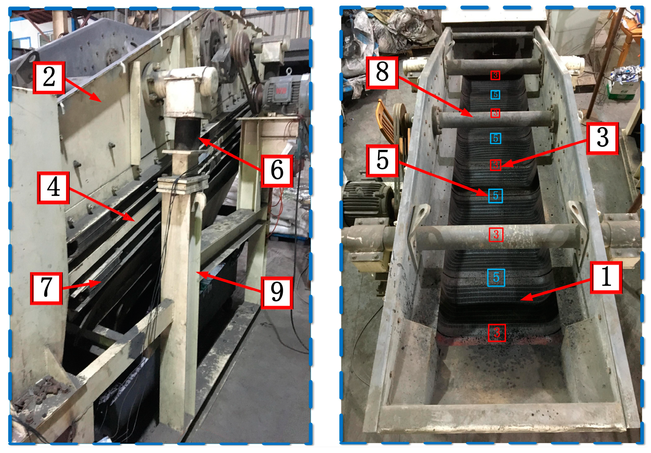
2.1. Experimental Apparatus
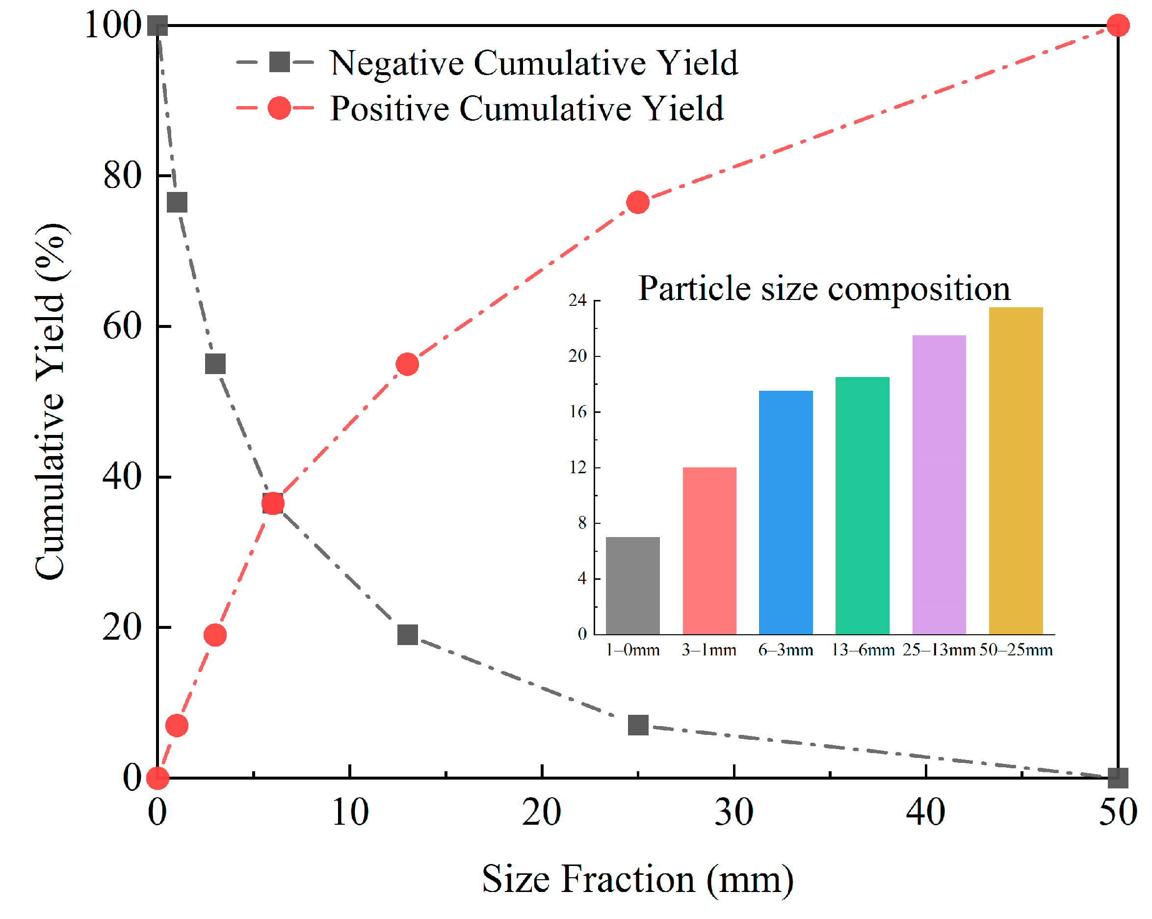
Figure 1 shows the kinetic test system and the screening experimental system, comprising a feeding unit, a VFFS, a frequency conversion control unit, a dynamic testing and analysis unit, a connecting unit, and a multi-stage reclaiming screening performance evaluation unit. The frequency conversion control unit comprises a circuit breaker and a frequency converter. The dynamic test and analysis unit consists of an acceleration sensor, a DASP acquisition instrument, and a computer with analysis software installed. The multi-stage reclaiming screening performance evaluation unit consists of a multi-stage receiving device under the screen and a series of standard sieves. The connection unit consists of bolts and nuts that can be used to fix both the main frame and the floating screen frame, thus enabling the conversion of VFFS to CVS. The multi-stage receiving unit under the screen consists of five sections. Each section has been assigned a numeral ranging from I to V in accordance with the materials’ moving direction. Sections I–IV were used for the collection of undersized materials, while Section V was used to collect oversized materials. There are 8 elastic sieve mats installed in the 0827 VFFS, and each elastic sieve mat has an array of key slot holes, with each hole being 3 mm wide and 10 mm long (aligned in the direction of flow along the screen). As shown in Figure 1, each section from I to IV corresponds to two elastic sieve mats on the screen.
A schematic of the VFFS is shown in Figure 2, which is mainly composed of elastic sieve mats, a main screen frame, the beams of the main screen frame, a floating screen frame, the beams of the floating screen frame, damping springs, shear springs, an inertial vibration exciter, and stents. The main screen frame is supported on the stents by the damping springs, and the inertial vibration exciter is installed on the main screen frame. The main screen frame and the floating screen frame are connected by shear springs. The beams of the main screen frame and the floating screen frame are staggered, and the two ends of the elastic sieve mat are installed on the beam of the main screen frame and the adjacent beam of the floating screen frame. Moreover, when the inertial vibration exciter is rotated by the driving motor, relative movement occurs between the main screen frame and the floating screen frame, thereby causing the elastic sieve mat to slacken and stretch periodically.

2.2. Materials

The coal material used in this study was obtained from Zoucheng City, Shandong, China. The particle-size distribution and moisture content of experimental coal samples were analyzed using a standard sieve and a constant temperature drying oven. The characteristics of the coal samples including their particle-size distribution and external moisture content are shown in Table 1.
The dominant particle size fractions were 50–25 mm and 25–13 mm, with corresponding yields equal to 23.5% and 21.5%, respectively. The size fractions of 13–6 mm, 6–3 mm, 3–1 mm, and 1–0 mm accounted for less than 20% of each coal sample, and the corresponding yields accounted for 18.5%, 17.5%, 12.0%, and 7.0%, respectively. It is worth noting that with the decrease in particle size, the moisture content of the material continues to increase. We added 350 g, 600 g, 800 g, and 1000 g of water to 15 kg of coal samples; then, we mixed the water and coal samples and sealed them to obtain coal samples with external moisture concentrations of 4.30%, 5.83%, 7.03%, and 8.19%, respectively, which were used to study the influence of external moisture content on screening.
The cumulative particle size characteristic curves of the coal samples of 50–0 mm are shown in Figure 3. The abscissa axis of the cumulative particle size characteristic curve represents the particle size of the material, and the vertical axis represents the cumulative yield above (or below) the sieve used to obtain the positive (or negative) cumulative particle size characteristic curves, which are symmetrical with respect to one another. Here we divide the undersized particles into three categories: (1) small undersized particles, whose sizes are less than 50% of aperture size; (2) medium undersized particles, whose sizes are equal to or greater than 50% but smaller than 85% of aperture size; and (3) near-mesh undersized particles, whose sizes are equal or greater than 85% but less than 100% of aperture size. When the cut size is 3 mm, it can be seen that small undersized particles, medium undersized particles, and near-mesh undersized particles coarse particles are 1.50–0 mm, 2.55–1.50 mm, and 3.00–2.55 mm. At this stage, the shape of the positive cumulative particle size characteristic curve is concave, indicating that the fine particle content in the material is high.

2.3. Evaluation

In this study, the screening efficiency and total amount of misplaced material were employed to evaluate screening performance. Screening efficiency can be calculated using Equation (1), and the total misplaced material can be determined using Equation (2). Multistage sampling and multilayer screening were employed to analyze the particle size of each section’s screening product [34].
E c = γ o × O c F c r × 100 E f = F f r γ o × O f F f r × 100 η = E c + E f 100
M o = M c + M f M c = 100 × γ o O f M f = 100 × γ u U c
In the equation above, γ o is the yield of oversized product (%), γ u is the yield of undersized product (%), O f is the fraction of fine particles in the oversized product (%), O c is the fraction of coarse particles in the oversized product (%), F c r is the fraction of coarse particles in the feed (%), F f r is the fraction of fine particles in the feed (%), U c is the fraction of coarse particles in the undersized product (%), E c represents the effective placement efficiency of the coarse particles (%), E f denotes the effective placement efficiency of fine particles (%), η is the screening efficiency (%), M o is the total misplaced material (%), M c is the misplaced material of coarse particles (%), and M f is the misplaced material of fine particles (%).

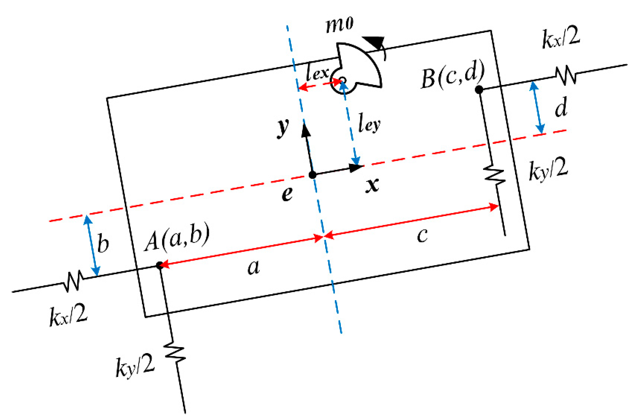
3. Dynamic Model of CVS

Some research gaps still exist with respect to the effect of the position of the damping spring on the dynamic characteristics of the screen. In this paper, while considering the stiffness force when establishing the CVS dynamic model, the influence of the damping springs’ position on the dynamic characteristics of the screen is also considered. It should be analyzed as a single mass when studying the kinetic response of a CVS, which can be simplified to the dynamic model shown in Figure 4. The coordinate system is established at the centroid of the screen, where the x-axis was set along the direction of the screen’s surface, while the y-axis was set along the direction perpendicular to the screen’s surface.
The damping of the screen only has a slight impact on its amplitude–frequency response in the far-resonance frequency region [24]. With regard to the analysis of the dynamic response of the CVS in the far-resonance frequency region, as the damping force is small relative to the stiffness force, the damping effect is ignored. A force analysis of the CVS was performed using the D’Alembert principle to obtain the following differential equation (Equation (3))
M x ¨ + k x x k x 2 Δ x = m 0 ω 2 r sin ω t M y ¨ + k y y + k y 2 Δ y = m 0 ω 2 r cos ω t J φ ¨ k x 2 x k x 2 d φ   d k x 2 x k x 2 b φ b + k y 2 y + k y 2 c φ c + k y 2 y + k y 2 a φ a = m 0 ω 2 r l e y sin ω t l e x cos ω t
where x = s 2 φ = d + b φ y = s 1 φ = c + a φ are the displacements along the x- and y-axes caused by screen rotation. M is the total vibrational mass (kg). m 0 , and r denote the weight of the exciters (kg) and the eccentric radius of the exciters (m), respectively. k x and k y are the stiffness of the damping spring along the x-axis and y-axis, respectively (N/m). J is the rotational inertia of the screen around the center of mass (kg m2). x and y are the displacements of the centroid of the screen along the x- and y-axes, respectively (m). x ¨ and y ¨ are the accelerations of the centroid of the screen along the x- and y-axes, respectively (rad/s2). φ is the angular displacement of the centroid (rad). φ ¨ is the angular acceleration of the centroid (rad/s2). l e x and l e y are the distances from the rotation center of the exciter to the centroid of the screen along the x- and y-axes (m). a and c are the coordinates of the front damping spring and the rear damping spring, respectively (m), along the x-axis. b and d are the coordinates of the front damping spring and the rear damping spring along the y-axis, respectively (m). ω is the angular frequency of the exciter (rad/s).
Equation (3) is rewritten into matrix form in Equation (4):
M X ¨ + K X = F M 0 0 0 M 0 0 0 J x ¨ y ¨ φ ¨ + k x 0 k x d + b 2 0 k y k y c + a 2 k x d + b 2 c + a k y 2 k x d + b 2 4 + k y c + a 2 4 x y φ = m 0 ω 2 r sin ω t m 0 ω 2 r cos ω t m 0 ω 2 r l e y sin ω t l e x cos ω t
where M is the mass matrix, K is the stiffness matrix, X ¨ is the acceleration matrix, X is the displacement matrix, and F is the excitation force matrix. According to the mechanical vibration theory, the relationship between the acceleration matrix X ¨ and the displacement matrix X corresponds to that shown in the following equation.
X ¨ = ω 2 X
Incorporating Equation (5) into Equation (4) and simplifying the result yields Equation (6)
k x ω 2 M 0 k x d + b 2 0 k y ω 2 M k y c + a 2 d + b k x 2 c + a k y 2 d 2 + b 2 k x + c 2 + a 2 k y 2 ω 2 J 2 x y φ = m 0 ω 2 r sin ω t m 0 ω 2 r cos ω t m 0 ω 2 r l e y sin ω t l e x cos ω t
Equation (6) is a common form of a linear equation that contains three unknowns. By solving the dynamic equation, the displacement at the centroid of the screen can be determined; then, the displacement of any point x a , y a on the screen can be calculated using Equation (7).
X a = x y a φ Y a = y + x a φ

4. Results and Discussion

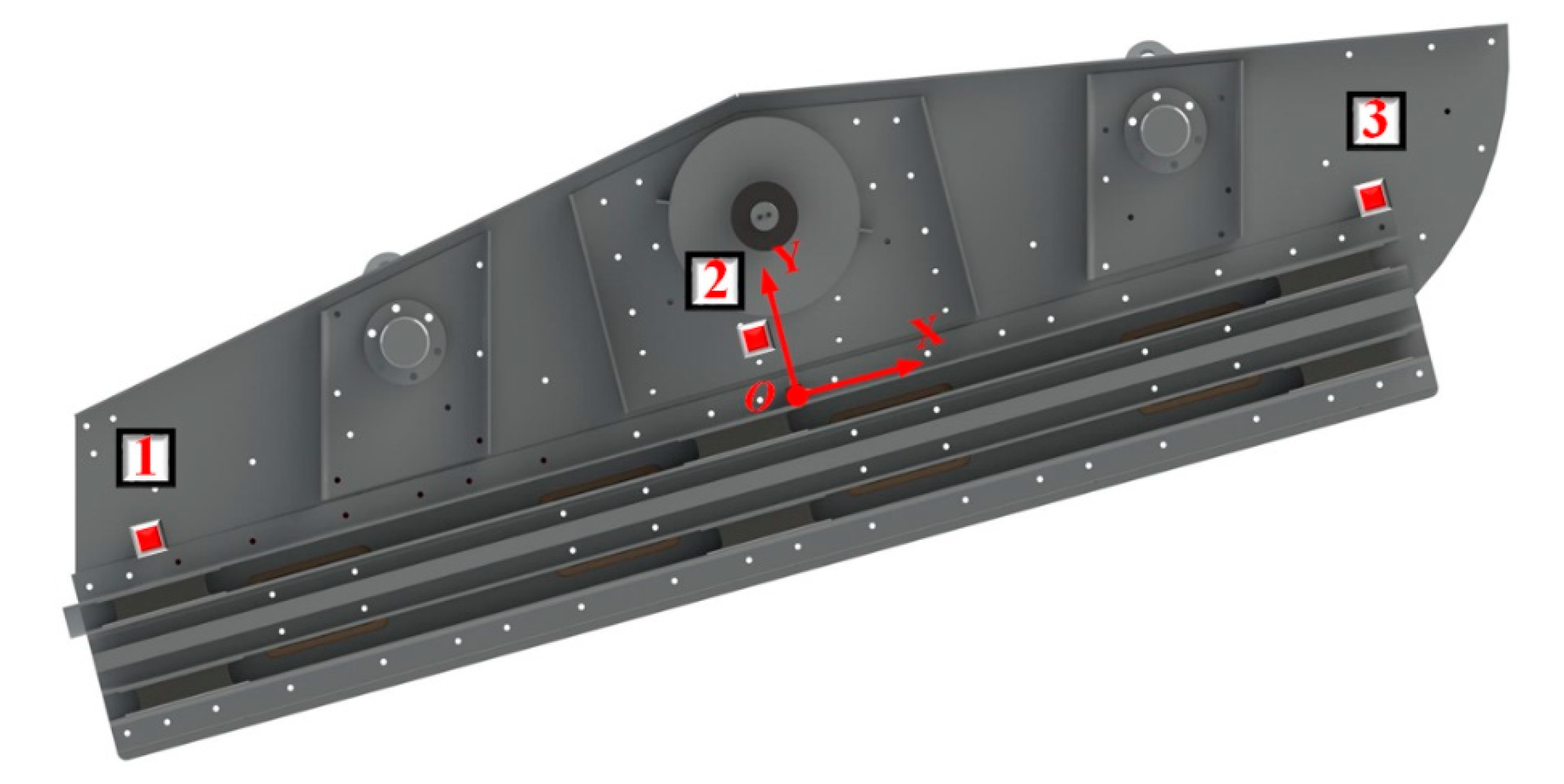
4.1. Dynamic Analysis of CVS

The experimental equipment parameters are shown in Table 2. The parameters in the new model were set according to the parameters of the experimental equipment, and the dynamic response of the new model was obtained through theoretical calculation.
To show the overall dynamic response of the CVS in more detail, a total of three test points were set, which were designated as test points 1, 2, and 3. Test points 1, 2, and 3 are located at the discharge end, the centroid, and the feed end of the screen, respectively. The test points’ arrangement is shown in Figure 5.
The centroid of the screen is used as the coordinate origin to establish a Cartesian coordinate system. The directions of the x-axis and y-axis are consistent with the directions in the above dynamic characteristics analysis, and the coordinates of the measurement points are shown in Table 3.
To test the dynamic response of the CVS, the main frame and the floating screen frame were fixed as a whole using a connection unit so as to realize the conversion of the VFFS to a CVS. When the screen runs smoothly and operates at 13.125 Hz, the dynamic test and analysis unit acquires acceleration signals from each test point on the x-axis and y-axis. Using the principle of double integration, the displacement characteristics in the time domain were obtained from the measured steady-state acceleration signals. The actual tested displacement trajectories and theoretically calculated displacement trajectories are listed in Figure 6. It can be seen that the new theoretical model can better reflect the motion trajectory of the CVS.

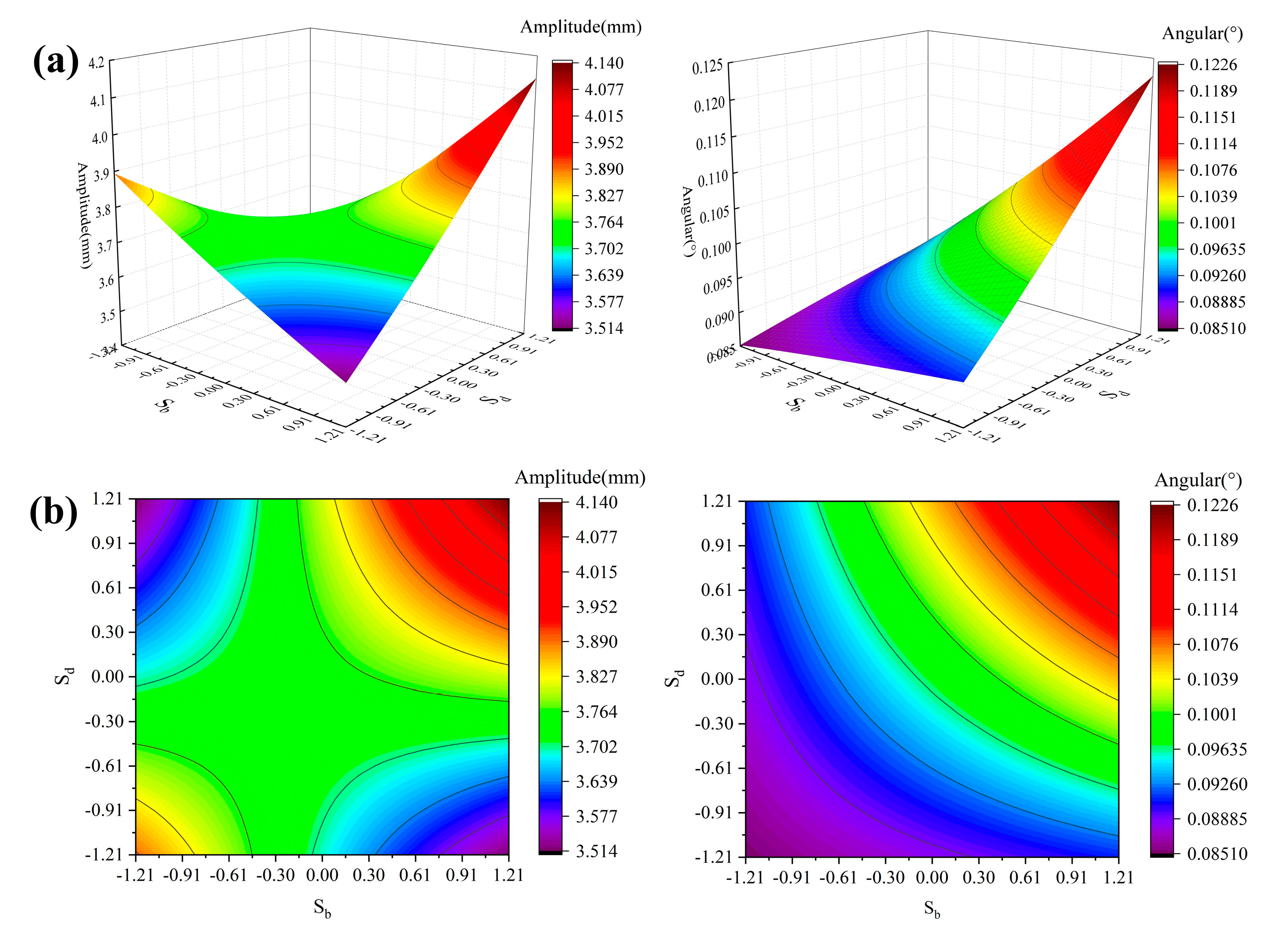
4.2. Influence of the Damping Spring Position on Screen Dynamic Responses

In order to satisfy the requirements for stable screen operation, the damping springs were generally arranged symmetrically around the centroid of the screen along the x-axis, while the arrangement of the damping springs along the y-axis assumed no specific form. Therefore, under the condition of a = c , Equation (6) was solved using Cramer’s law to obtain the motion equation (Equation (8)) of the centroid of screen, from which it can be seen that the position of the damping spring in the direction of the screen’s surface and the vertical direction of the screen’s surface has an effect on the dynamics of the screen. The position of the damping spring along the x-axis is fixed; then, its position along the y-axis is changed to analyze the influence of the damping spring position on the screen dynamics.
x = m 0 ω 2 r k x ω 2 M 2 d 2 + b 2 k x + 2 c 2 + a 2 k y 4 ω 2 J 2 k x d + b l e y sin ω t + 2 k x d + b l e x cos ω t 2 d 2 + b 2 k x + 2 c 2 + a 2 k y 4 ω 2 J d + b 2 k x 2 k x ω 2 M y = m 0 ω 2 r k y ω 2 M cos ω t φ = 4 m 0 ω 2 r l e x cos ω t + 2 m 0 ω 2 r d + b k x k x ω 2 M 4 m 0 ω 2 r l e y sin ω t 2 d 2 + b 2 k x + 2 c 2 + a 2 k y 4 ω 2 J d + b 2 k x 2 k x ω 2 M
In Equation (8), it can be seen that the displacement along the x-axis and the angular displacement of the centroid are related to the damping spring positions, and the amplitude along the y-axis is independent of the damping springs’ positions.
The dimensionless treatment of spring positions b and d yields S b = b / a ; S d = d / a . Let d and b assume values every 0.05 m from −1 m to 1 m, and calculate the amplitude of the screen centroid along the x-axis and the angular displacement of the centroid. Employing S b as the x-axis and S d as the y-axis, draw the three-dimensional surface of the amplitude X and the angular displacement φ (see Figure 7).
To facilitate the observation of the variation in amplitude and angular displacement with the position of the damping spring, the three-dimensional surface was projected on the x–y plane to obtain the two-dimensional plot in Figure 7b.
Analyzing Figure 7 shows that when S b and S d have opposite signs, the points S b , S d belong to the second and fourth quadrants of the x–y plane. As the absolute values of S b and S d increase, the amplitude decreases, and the curved surface shows a downward curving trend. When S b = S d = 1.21 , the minimum amplitude of 3.514 mm is obtained. When S b and S d have the same signs, the points S b , S d correspond to the first and third quadrants of the x–y plane. When the absolute values of S b and S d increase, the amplitude increases, and the curved surface presents an upward warping trend. In terms of the curvature of three-dimensional surfaces, the first quadrant is higher than the fourth quadrant. At S b = S d = 1.21 , the amplitude reaches a maximum of 4.138 mm.
The variation in the angular displacement is very different from that of the amplitude. As shown in Figure 7, the increases in S b and S d cause the angular displacement to increase continuously, and the three-dimensional surface shows an upward trend during the change of S b , S d from (−1.21, −1.21) to (1.21, 1.21), where the angular displacements achieves a maximum at (1.21, 1.21) and a minimum at (−1.21, −1.21), with corresponding values of 0.1226° and 0.0893°, respectively.
When S b = S d = 1.21 , the amplitude and angular displacement assume extreme values. Analyzing the force on the screen shows that as the position of the damping spring moves away from the centroid of the screen, the torque of the stiffness force on the centroid of the screen to increase, resulting in an increase in the angular displacement of the screen. It can be seen from Equation (7) that the displacement at the position of the damping spring is related to the angular displacement of the screen, and the stiffness force of the damping spring is related to the amplitude of its position, so the variation in the position of the damping spring affects the amplitude of the screen.
When using Equation (7) to calculate the dynamic responses at any point on the screen, the dynamic responses at locations away from the centroid of the screen are more sensitive to the location of the damping spring. In summary, the screen’s operation is more stable when the damping springs are symmetrically arranged up and down around the centroid of the screen. If a more positive form of motion is pursued, the damping springs can all be installed above the centroid of the screen in accordance with the prerequisite of meeting the stable operation of the screen.

4.3. Comparison of Screening Performance between CVS with VFFS under Different External Moisture Concentrations

The VFFS is a two-body system developed based on a single-body CVS, wherein the main and floating screen frames drive the VFFS’s polyurethane elastic sieve mat to periodically stretch and relax. The vibration intensities of the CVS’s and VFFS’s screen bodies are similar, but the vibration intensity of the elastic screen surface of the VFFS can reach 30–50 g. To analyze the screening performance of screen surfaces of different vibrating intensities when treating materials with different external moisture concentrations, which is of great significance to improving the screening efficiency of VFFS, a rigid screen surface with elastic screen mats instead of a CVS is approximated as an elastic screen surface with low vibration intensity, and multistage sampling and multilayer screening are used to analyze the yield of each material section of the VFFS and CVS [35]. The operating conditions for the screening experiments are listed in Table 4.

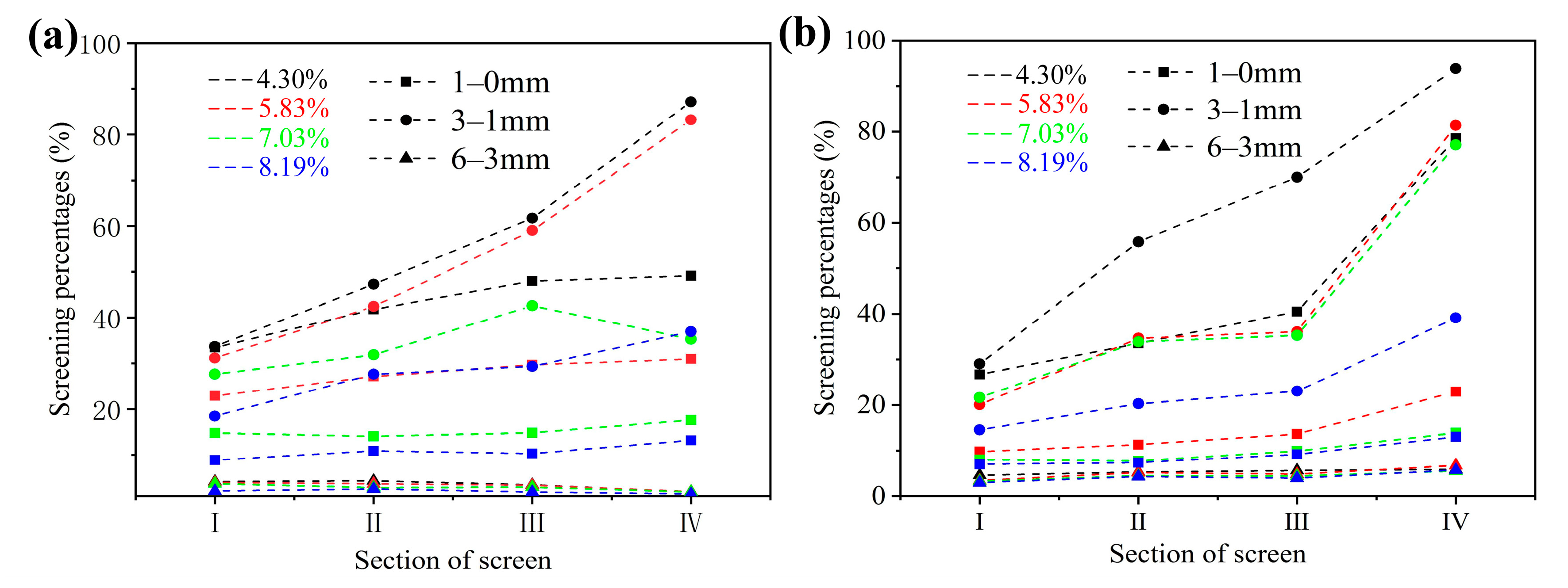
4.3.1. The Screening Percentages of Different Size Fractions of VFFS and CVS

With the increase in the external moisture content of the material, the screening percentages of the 6–0 mm size fractions in different sections of the VFFS and CVS decrease, while the screening percentages of the 6–0 mm size fractions in different sections on the CVS decrease more significantly than those of the VFFS, so the screening percentages of the 6–0 mm size fractions of the CVS are more affected by the external moisture content of the material. From the feed end to the discharge end (I–IV), the sticky and wet materials undergo continuous desorption and depolymerization under the action of the screen surface, the layering state of the material continues to improve, and the screening percentages of the 1–0 mm and 3–1 mm size fractions on the VFFS and CVS under different external moisture concentrations from sections I to IV show an increasing trend, while the screening percentages of the 3–1 mm size fractions in sections I–IV of the VFFS and CVS are greater than those of the 1–0 mm size fractions. In sticky and wet materials, the liquid bridge force is proportional to the difference in particle size, and particles of the 1–0 mm size fractions are more difficult to detach from large particles and the surface of the screen than particles of 3–1 mm size fractions; thus, it is difficult for the particles of the 1–0 mm size fractions to pass through the surface of the screen.
Interestingly, when the external moisture concentrations of the material are 4.30%, 5.83%, 7.03%, and 8.19%, the screening percentages of the 3–1 mm size fractions on VFFS section I are 33.70%, 31.18%, 27.65%, and 18.50%, and the screening percentages of the 3–1 mm size fractions on CVS section I are 29.04%, 20.094%, 21.64%, and 14.58%, respectively. It can be seen that under different external moisture concentrations, the screening percentages of the 3–1 mm size fractions at the feeding end of the VFFS are higher than that at the feeding end of CVS. This is because the VFFS screen surface with high vibration intensity can quickly loosen and spread the incoming material, and the large vibration intensity screen surface is also conducive to the depolymerization and stratification of sticky and wet materials, providing a good environment for the penetration of particles. Compared with a CVS, a VFFS with high-vibrating-strength screen faces has more advantages at the feed end.
In Figure 8, it is evident that when the external moisture concentrations are 4.30%, 5.83%, 7.03%, and 8.19%, the screening percentages of 3–1 mm size fractions in section IV of the CVS are 93.85%, 81.36%, 77.09%, and 39.14%, while the screening percentages of the 3–1 mm size fractions in section IV of the VFFS are 87.15%, 83.24%, 35.28%, and 36.95%, respectively. Except for the case of an external moisture content of 5.83%, the screening percentages of the 3–1 mm size fractions in section IV of the CVS are greater than those of section IV of the VFFS. This is because as the material reaches the discharge end, the layering state of the material on the screen’s surface is better, and the advantage of the low vibration intensity of the CVS screen surface begins to appear. When the vibration intensity is low, the number of times the material contacts the screen surface increases, which gives the material more opportunities to pass through the screen’s surface. At the same time, the angle between the oval trajectory along the long axis of the discharge end of the screening machine and the direction of material movement is an obtuse angle, which will hinder the discharge of the material, allowing the material at the discharge end to be inspected and screened. At the discharge end of the CVS, the elliptical trajectory dominates the action of the material, while the high-vibration-intensity screen surface of the VFFS will weaken the influence of the elliptical trajectory of the discharge end. These all lead to greater advantages in the screening of materials by the CVS at the discharge end.

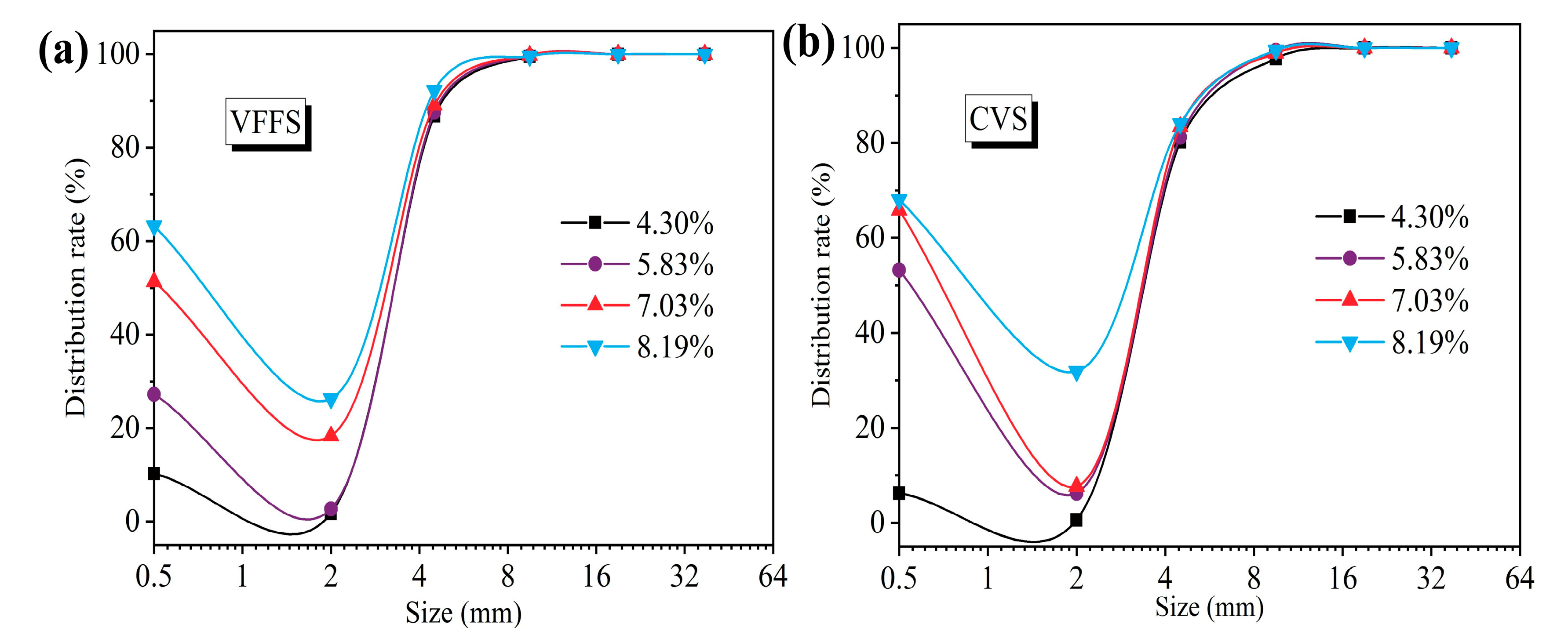
4.3.2. The Distribution of Material on VFFS and CVS under Different External Moisture Concentrations

It can be seen from Figure 9 that as the external moisture content of material increases, the overflow partition curves shift to the left, resulting in a gradual decrease in the distribution of particle sizes. Among them, under the conditions of external moisture concentrations of 4.30%, 5.83%, 7.03%, and 8.19%, the particle size distribution of the VFFS was 3.28 mm, 3.26 mm, 3.09 mm, and 2.95 mm, and the particle size distribution of the CVS was 3.40 mm, 3.37 mm, 3.32 mm, and 2.95 mm, respectively. Under different external moisture concentrations, the particle size distribution of the CVS was greater than that of the VFFS, but the difference in the particle size distribution between the two was not large.
Within the selected external moisture content range, with the increase in the external moisture content, the adhesion between the particles is continuously enhanced, and the adhesion between the medium undersized particles (2.55–1.5 mm) and large-sized particles (>3 mm) is less than that between the small undersized particles (<1.5 mm) and large-sized particles (>3 mm), resulting in the distribution rate of the medium undersized particles on the VFFS and CVS being lower than that of the small undersized particles. As the external moisture content increases, the adhesion between the particles increases. Since small undersized particles do not easily detach from large particles, a large number of small particles adhere to large-sized particles and enter the overflow product; this leads to increased upward warping on the left side of the overflow partition curves. At the same time, it can also be seen from the overflow partition curves that it is difficult to screen out small undersized particles with moisture, whether using a VFFS or a CVS.
It can be seen from Figure 9 that for the external moisture concentrations of 4.30%, 5.83%, 7.03%, and 8.19%, the distribution rates of 1–0 mm size fractions on the VFFS are 10.24%, 27.26%, 51.33%, and 63.21%, and the distribution rates of the 1–0 mm size fractions on the CVS are 6.22%, 53.22%, 65.84%, and 68.03%, respectively. When the external moisture content is 4.30%, the distribution rate of the 1–0 mm size fractions on the CVS is lower than that of the VFFS, and the CVS has a lower screen surface vibration intensity than the VFFS, so the particles on the CVS have more contact with screen’s surface, which is more conducive to the particles passing through the screen’s surface. When the external moisture content is greater than 4.30%, the distribution rate of the 1–0 mm size fractions on the CVS is greater than that of the VFFS, and when screening wet materials with greater viscosity, the screen surface with the large vibration intensity offered by the VFFS is more conducive to the dispersion and stratification of viscous wet materials.

4.3.3. Effect of External Moisture Content on the Screening Performance of VFFS and CVS

During the screening of the VFFS and CVS, with the continuous increase in the external moisture content, the total number of misplaced materials and the misplaced materials of fine particles increased, and the misplaced materials of coarse particles showed a decreasing trend, among which the change of fine-particle misplaced materials determined the change trend of the total misplaced materials. Due to the increase in the external moisture content, the agglomeration and adhesion between the particles are serious, resulting in particles smaller than the aperture size adhering to the large particles and following them into the overflow product; at the same time, the external moisture content increases, and the agglomeration of particles makes it more difficult for the particles near the screen apertures that are larger than these apertures to pass through the screen’s surface, thus reducing the phenomenon in which overflow product enters the underflow product.
It can be seen from Figure 10, when the external moisture content was 8.19%, the total misplaced materials of the VFFS and CVS reached the maximum values, which were 9.02% and 11.49%, respectively. Under different external moisture concentrations, there were more fine-particle misplaced materials of the CVS than the VFFS. When the external moisture content was 4.30%, the quantities of fine-particle misplaced materials of the VFFS and CVS were 2.40% and 3.89%, and the difference between the two was the largest. The particles on the CVS screen’s surface have more contact time with the screen’s surface, resulting in an increase in the possibility of lamellar particles in large particles passing through the screen’s surface, which is more obvious under the condition of low external moisture content, such as 4.30%.
For the VFFS and the CVS, with the increase in external moisture content, the screening efficiency and effective placement efficiency of fine particles continue to decrease, while the effective placement efficiency of coarse particles increases. When screening materials with different external moisture concentrations, the effective placement efficiency of coarse particles in the VFFS is greater than that of the CVS. It can be seen from Figure 11, when the external moisture content is 4.30%, the screening efficiencies of the CVS and VFFS are 92.54% and 92.19%, respectively, rendering the screening performance of the CVS better than that of the VFFS. With the external moisture content increasing to 5.83%, 7.03%, and 8.19%, the screening efficiencies of the CVS were 72.27%, 67.05%, and 51.22%, and the screening efficiencies of the VFFS were 85.48%, 67.10%, and 58.34%, showing that the screening performance of the VFFS was better than that of the CVS. It is easier for materials with low external moisture content to loosely stratify, and a screen surface with low vibration intensity can also loosen material. The particles on the screen’s surface with small vibration intensity have more contact with the screen’s surface, and the material has a greater chance of passing through the screen surface, so the CVS with low vibration intensity has more advantages. In materials with high external moisture content, the adhesion between particles is large, and a screen surface with high vibration strength is required to destroy the adhesion between particles to achieve the depolymerization and loosening of particles, so the screening effect of the VFFS is better when screening materials with larger viscosity. When the external moisture content of the material increased from 4.30% to 8.19%, the screening efficiency of the VFFS and CVS decreased by 33.85% and 41.32%, respectively. It can be seen that the screening efficiency of the VFFS and the CVS are affected by the external moisture content of the material, but the screening efficiency of the CVS is more sensitive to the external moisture content of the material, and the screening performance of the CVS deteriorates more seriously.

5. Conclusions

1. A model of a CVS’s dynamics considering damping springs has been presented. It has been shown that the arrangement of the damping springs influences the amplitude and angular displacement of the screen when the vertical distance between the front and rear damping springs and the center of mass of the screen is the same. When the front and rear damping springs are arranged above the centroid, below the centroid, and symmetrically around the centroid, the amplitude of the centroid of the screen continuously decreases, and the angular displacement of the centroid decreases first and then increases.
2. As the external moisture content of the material increases, the screening percentages of the 6–0 mm size fractions in section I–IV on the CVS decrease more significantly than those of the VFFS. In section I, the screening percentages of the 3–1 mm size fractions in the VFFS are higher than those of the CVS, and the opposite is true for section IV. The VFFS, offering large vibration intensity at the feeding end, is more conducive to the loosening and spreading of material, while the CVS, with its small vibration intensity at the discharge end, will increase the number of times the material contacts the screen’s surface.
3. As the external moisture content increases, a large number of small particles adhere to large particles and enter the overflow product, which leads to an increase in upward warping on the left side of the overflow partition curve. It is also evident from the overflow partition curve that it is difficult for VFFS or CVS to screen out small undersized particles with moisture.
4. When the external moisture content is 4.30%, the screening efficiencies of the CVS and VFFS are 92.54% and 92.19%, respectively. With the external moisture content increasing to 5.83%, 7.03%, and 8.19%, the screening efficiencies of the CVS were 72.27%, 67.05%, and 51.22%, and the screening efficiencies of the VFFS were 85.48%, 67.10%, and 58.34%, thus demonstrating that the screening performance of the VFFS was better than that of the CVS. When the external moisture content of the material increased from 4.30% to 8.19%, the screening efficiency of the VFFS and the CVS decreased by 33.85% and 41.32%, respectively. The screening efficiency of the CVS is more sensitive to the external moisture content of the material.

Author Contributions

Conceptualization, C.Y. and X.W.; Data curation, R.G. and R.L.; Funding acquisition, X.W.; Investigation, Y.W.; Methodology, R.G.; Resources, X.W.; Software, X.Z.; Supervision, X.W.; Writing–original draft, R.G.; Writing–review & editing, R.G. and Y.W. All authors have read and agreed to the published version of the manuscript.

Funding

This work was financially supported by the Anhui Province Major Science and Technology Achievements Engineering Research and Development Special Project under Grant (No. 202103c08020007) and the Fundamental Research Funds for the Central Universities (No. 2022YJSHH15).

Acknowledgments

The authors would like to thank the company of TianGong technology for its support in enabling this research.

Conflicts of Interest

The authors declare no conflict of interest.

References

  1. Xia, X.; Jing, W.; Zhang, Z.; Wang, L.; Zhang, H. Simulation research, application status and development trend of vibrating screen. J. Cent. South Univ. (Sci. Technol.) 2020, 51, 2689–2706. [Google Scholar]
  2. Elskamp, F.; Kruggel-Emden, H. Review and benchmarking of process models for batch screening based on discrete element simulations. Adv. Powder Technol. 2015, 26, 679–697. [Google Scholar] [CrossRef]
  3. Yang, X.; Zhao, Y.; Luo, Z. Dry Cleaning of Fine Coal Based on Gas-Solid Two-Phase Flow: A Review. Chem. Eng. Technol. 2017, 40, 439–449. [Google Scholar] [CrossRef]
  4. Zhou, Z.; Huang, L.; Jiang, H.; Wen, P.; Zhao, L.; Zhao, Y.; Duan, C.; Luo, Z.; Wang, Z.; Liu, C.; et al. Kinematics of elastic screen surface and elimination mechanism of plugging during dry deep screening of moist coal. Powder Technol. 2019, 346, 452–461. [Google Scholar] [CrossRef]
  5. Guerreiro, F.; Gedraite, R.; Ataíde, C. Residual moisture content and separation efficiency optimization in pilot-scale vibrating screen. Powder Technol. 2016, 287, 301–307. [Google Scholar] [CrossRef]
  6. Govender, A.; van Dyk, J. Effect of wet screening on particle size distribution and coal properties☆. Fuel 2003, 82, 2231–2237. [Google Scholar] [CrossRef]
  7. Boylu, F.; Çinku, K.; Çetinel, T.; Karakaş, F.; Güven, O.; KaraağaçlIoğlu, I.E.; Çelik, M.S. Effect of Coal Moisture on the Treatment of a Lignitic Coal through a Semi-Pilot-Scale Pneumatic Stratification Jig. Int. J. Coal Prep. Util. 2015, 35, 143–154. [Google Scholar] [CrossRef]
  8. Sahu, A.K.; Biswal, S.K.; Parida, A. Development of Air Dense Medium Fluidized Bed Technology For Dry Beneficiation of Coal—A Review. Int. J. Coal Prep. Util. 2009, 29, 216–241. [Google Scholar] [CrossRef]
  9. Zhao, L.; Liu, C.; Yan, J.; Xu, Z. Numerical simulation on segregation process of particles using 3D discrete element method. Acta Phys. Sin. 2010, 59, 1870–1876. [Google Scholar] [CrossRef]
  10. Zhao, L.; Liu, C.; Yan, J.; Jiang, X.; Zhu, Y. Numerical simulation of particle screening process based on 3D discrete element method. J. China Coal Soc. 2010, 35, 307–311. [Google Scholar] [CrossRef]
  11. Cleary, P.W.; Sinnott, M.D.; Morrison, R.D. Separation performance of double deck banana screens—Part 2: Quantitative predictions. Miner. Eng. 2009, 22, 1230–1244. [Google Scholar] [CrossRef]
  12. Cleary, P.W.; Sinnott, M.D.; Morrison, R.D. Separation performance of double deck banana screens—Part 1: Flow and separation for different accelerations. Miner. Eng. 2009, 22, 1218–1229. [Google Scholar] [CrossRef]
  13. Dong, K.; Esfandiary, A.H.; Yu, A.B. Discrete particle simulation of particle flow and separation on a vibrating screen: Effect of aperture shape. Powder Technol. 2017, 314, 195–202. [Google Scholar] [CrossRef]
  14. Dong, K.; Yu, A.; Brake, I. DEM simulation of particle flow on a multi-deck banana screen. Miner. Eng. 2009, 22, 910–920. [Google Scholar] [CrossRef]
  15. Davoodi, A.; Bengtsson, M.; Hulthén, E.; Evertsson, C. Effects of screen decks’ aperture shapes and materials on screening efficiency. Miner. Eng. 2019, 139, 105699. [Google Scholar] [CrossRef]
  16. Makinde, O.A.; Mpofu, K.; Ramatsetse, B. Mining business optimisation through a reconfigurable vibrating screen design. Afr. J. Sci. Technol. Innov. Dev. 2016, 8, 88–96. [Google Scholar] [CrossRef]
  17. Ramatsetse, B.; Mpofu, K.; Makinde, O. Failure and sensitivity analysis of a reconfigurable vibrating screen using finite element analysis. Case Stud. Eng. Fail. Anal. 2017, 9, 40–51. [Google Scholar] [CrossRef]
  18. Shanmugam, B.K.; Vardhan, H.; Raj, M.G.; Kaza, M.; Sah, R.; Harish, H. Evaluation of a new vibrating screen for dry screening fine coal with different moisture contents. Int. J. Coal Prep. Util. 2019, 42, 752–761. [Google Scholar] [CrossRef]
  19. Jiang, H.; Zhao, Y.; Duan, C.; Liu, C.; Wu, J.; Diao, H.; Lv, P.; Qiao, J. Dynamic characteristics of an equal-thickness screen with a variable amplitude and screening analysis. Powder Technol. 2017, 311, 239–246. [Google Scholar] [CrossRef]
  20. Jiang, H.; Duan, C.; Wu, J.; Zhao, Y.; Liu, C.; Luo, Z.; Dong, L.; Zhang, B.; Wang, Z.; Zhang, C.; et al. Kinematics characteristics of the vibrating screen with rigid-flexible screen rod and the behavior of moist coal particles during the dry deep screening process. Powder Technol. 2017, 319, 92–101. [Google Scholar] [CrossRef]
  21. Zhou, E.; Yan, G.; Weng, X.; Zhang, Z.; Zhao, P.; Zhang, B. A novel and low cost coal separation process: Combination of deep screening classification and gravity separation. Powder Technol. 2020, 367, 568–575. [Google Scholar] [CrossRef]
  22. Zhao, Y.; Liu, C.; Fan, M.; Wei, L. Research on acceleration of elastic flip–flow screen surface. Int. J. Miner. Process. 2000, 59, 267–274. [Google Scholar] [CrossRef]
  23. Wu, J.; Liu, C.; Jiang, H.; Zhang, B. A vibration-test-based calculation method of screening material mass of a mining crank-link type flip-flow screen. Energy Sources Part A Recover. Util. Environ. Eff. 2020, 1–21. [Google Scholar] [CrossRef]
  24. Gong, S.; Oberst, S.; Wang, X. An experimentally validated rubber shear spring model for vibrating flip-flow screens. Mech. Syst. Signal Process. 2020, 139, 106619. [Google Scholar] [CrossRef]
  25. Yu, C.; Wang, X.; Gong, S.; Pang, K.; Zhao, G.; Zhou, Q.; Lin, D.; Xu, N. Stability analysis of the screening process of a vibrating flip-flow screen. Miner. Eng. 2021, 163, 106794. [Google Scholar] [CrossRef]
  26. Yu, C.; Wang, X.; Pang, K.; Zhao, G.; Sun, W. Dynamic Characteristics of a Vibrating Flip-Flow Screen and Analysis for Screening 3 mm Iron Ore. Shock. Vib. 2020, 2020, 1–12. [Google Scholar] [CrossRef]
  27. Xiong, X.; Niu, L.; Gu, C.; Wang, Y. Vibration characteristics of an inclined flip-flow screen panel in banana flip-flow screens. J. Sound Vib. 2017, 411, 108–128. [Google Scholar] [CrossRef]
  28. Chen, B.; Yu, C.; Gong, S.; Wang, X. Dynamic characteristics of LIWELL flip-flow screen panel and particle movement. Chem. Eng. Sci. 2021, 245, 116853. [Google Scholar] [CrossRef]
  29. Akbari, H.; Ackah, L.; Mohanty, M. Performance Optimization of a New Air Table and Flip-flow Screen for Fine Particle Dry Separation. Int. J. Coal Prep. Util. 2017, 40, 581–603. [Google Scholar] [CrossRef]
  30. Li, H.; Liu, C.; Shen, L.; Zhao, L.; Li, S. Kinematics characteristics of the flip-flow screen with a crankshaft-link structure and screening analysis for moist coal. Powder Technol. 2021, 394, 326–335. [Google Scholar] [CrossRef]
  31. Yu, C.; Geng, R.; Wang, X. A Numerical Study of Separation Performance of Vibrating Flip-Flow Screens for Cohesive Particles. Minerals 2021, 11, 631. [Google Scholar] [CrossRef]
  32. Xu, N.; Yu, C.; Gong, S.; Zhao, G.; Lin, D.; Wang, X. Numerical study and multi-objective optimization of flexible screening process of flip-flow screen: A DEM-FEM approach. Adv. Powder Technol. 2022, 33, 103650. [Google Scholar] [CrossRef]
  33. Lin, D.; Ji, J.; Yu, C.; Wang, X.; Xu, N. A non-linear model of screen panel for dynamics analysis of a flip-flow vibrating screen. Powder Technol. 2023, 418, 118312. [Google Scholar] [CrossRef]
  34. Jiang, H.; Zhao, Y.; Duan, C.; Zhang, C.; Diao, H.; Wang, Z.; Fan, X. Properties of technological factors on screening performance of coal in an equal-thickness screen with variable amplitude. Fuel 2017, 188, 511–521. [Google Scholar] [CrossRef]
  35. Delaney, G.W.; Cleary, P.W.; Hilden, M.; Morrison, R.D. Testing the validity of the spherical DEM model in simulating real granular screening processes. Chem. Eng. Sci. 2012, 68, 215–226. [Google Scholar] [CrossRef]
Figure 1. Kinetic test system and the experimental screening system.
Minerals 13 00585 g001
Figure 2. Schematic illustration of the VFFS: 1. Elastic sieve mat; 2. main screen frame; 3. beam of the main screen frame; 4. floating screen frame; 5. beam of floating screen frame; 6. damping spring; 7. shear spring; 8. inertial vibration exciter; 9. stents.
Minerals 13 00585 g002
Figure 3. Cumulative particle size characteristic curves of coal samples.
Minerals 13 00585 g003
Figure 4. Dynamic model of CVS.
Minerals 13 00585 g004
Figure 5. Test points of acceleration sensor.
Minerals 13 00585 g005
Figure 6. Comparison of the experimental and theoretical trajectory: (a)—experimental test trajectory; (b)—theoretical calculation of the new model.
Minerals 13 00585 g006
Figure 7. Variation of amplitude and angular displacement with S b and Sd: ((a)—3D; (b)—2D).
Minerals 13 00585 g007
Figure 8. The screening percentages of different size fractions in different sections under different external moisture concentrations: (a) the VFFS and (b) the CVS.
Minerals 13 00585 g008
Figure 9. The overflow partition curves obtained under different external moisture concentrations: (a) the VFFS and (b) the CVS.
Minerals 13 00585 g009
Figure 10. Misplaced materials under external moisture content: (a) VFFS and (b) CVS.
Minerals 13 00585 g010
Figure 11. Screening efficiency under external moisture content: (a) VFFS and (b) CVS.
Minerals 13 00585 g011
Table 1. Particle-size distribution and external moisture content of coal samples.
Size Fraction (mm)50–2525–1313–66–33–11–0Total
Yield (%)23.521.518.517.512.07.0100
Moisture content (%)0.901.602.002.503.603.802.07
Table 2. 0827 VFFS parameters.
Symbol M m 0 r k x k y lex
UnitkgkgmN/mN/mm
Value1226.6648.780.085456022009472600.05452
Symbolley J a b cd
Unitmkg·m2mmmm
Value0.407411134.74−0.824040.154730.890450.15459
Table 3. Location of test points.
Test Point 1Test Point 2Test Point 3
Discharge of the screenCentroid of the screenFeed of the screen
(−1401.89 mm, 87.61 mm)(−19.59 mm, 166.09 mm)(1347.52 mm, 87.61 mm)
Table 4. Summary of experimental operating conditions.
VFFSCVS
Screen declination ( ° )1515
Screen speed (r/min)787.5787.5
Feed rate (kg/s)7.57.5
Feeding mechanismSilo feedingSilo feeding
Screen deck materialpolyurethanepolyurethane
Screen surface Vibration intensity (g)143
Disclaimer/Publisher’s Note: The statements, opinions and data contained in all publications are solely those of the individual author(s) and contributor(s) and not of MDPI and/or the editor(s). MDPI and/or the editor(s) disclaim responsibility for any injury to people or property resulting from any ideas, methods, instructions or products referred to in the content.

