Article

Promotion Mechanism of Ammonium Formate in Ammonium Salt Leaching Process for Weathered Crust Elution-Deposited Rare Earth Ores

1
School of Resource and Safety Engineering, Wuhan Institute of Technology, Wuhan 430073, China
2
Key Laboratory for Green Chemical Process of Ministry of Education, Wuhan Institute of Technology, Wuhan 430073, China
*
Author to whom correspondence should be addressed.
Minerals 2023, 13(10), 1286; https://doi.org/10.3390/min13101286
Submission received: 12 September 2023 / Revised: 25 September 2023 / Accepted: 27 September 2023 / Published: 30 September 2023
(This article belongs to the Special Issue Recent Developments on the Leaching Process of Rare Earth Ore)

Abstract

:
Weathered crust elution-deposited rare earth ores (WREOs) are significant strategic mineral resources. In industry, in situ leaching technology is usually applied with ammonium chloride and ammonium sulfate as the leaching solution. However, the slow seepage velocity of the leaching solution and low rare earth leaching efficiency still need to be improved. Ammonium formate can effectively improve the WREO leaching process. In order to further explore the effects of ammonium formate on the ammonium salt leaching process for WREOs, ammonium chloride and ammonium sulfate compounded with ammonium formate were used as leaching agents to determine their effects on leaching efficiency, seepage velocity and swelling. The results show that in the presence of ammonium formate, the rare earth leaching efficiencies with ammonium chloride and ammonium sulfate are both slightly increased, the seepage velocity of ammonium chloride and ammonium sulfate is increased by 1.67 × 10⁻⁴ cm·s−1 and 1.18 × 10⁻⁴ cm·s−1, and the swelling percentage falls by 0.14% and 0.37%, respectively. The thickness of the adsorbed water layer and thermogravimetric and XRD results confirm that ammonium formate can inhibit surface hydration and thus improve the WREO leaching process.

1. Introduction

Weathered crust elution-deposited rare earth ores (WREOs) are one of the most important types of rare earth deposits, mainly containing clay minerals such as illite and kaolin, in which rare earth exists as ions and adsorbs on the clay minerals. It is difficult to use the conventional physical beneficiation method to enrich and recover rare earth due to its low grade and fine mineral grain. The chemical leaching method is consequently used to extract rare earth ions [1]. At present, ammonium salts such as ammonium sulfate and ammonium chloride usually serve as leaching agents, and in situ leaching technology is employed to recover rare earths in the industry.
In order to efficiently exploit WREOs, many studies have been carried out. Chi et al. [2] found that the leaching rates of rare earth and aluminum with the three major ammonium salts follow the law of ammonium nitrate > ammonium chloride > ammonium sulfate. Tian et al. [3] investigated the chemical leaching processes of rare earths (REs) from WREOs from the viewpoints of kinetics, hydrodynamics and mass transfer. The results show that the leaching hydrodynamics follows the Darcy law. By examining the influence of various leaching factors on the leaching efficiency and the leaching rate, researchers search for new leaching agents. Xiao et al. [4] innovatively put forward the reduction leaching of rare earth from WREOs with ferrous sulfate. In addition, the application of magnesium sulfate was studied, and the results showed that the synergistic leaching of magnesium salt and calcium salt was identified as an excellent alternative leaching agent for further study [5].
Most of the above studies focus on leaching agents to discuss the ion exchange leaching process. However, the in situ WREO leaching process is a typical liquid–solid reaction, which involves not only the ion exchange chemical leaching process, but also the physical migration process of solution seepage. The ionic rare earth ore body undergoes particle transport and pore structure change during the leaching process, resulting in uneven percolation, preferential channels, leaching blind areas, etc., leading to structural changes in the ore body, low leaching efficiency and a waste of resources [6]. In addition, during the leaching process, the clay minerals will swell when in contact with the leaching solution due to the hydration reaction, which results in the destruction of inherent structure in the ore body and further causes geological disasters such as landslides. Deng et al. [7] investigated the hydration mechanism between the leaching agent and the ore surface and found that the fine particles tended to migrate with the leaching agent during the WREO leaching process. This behavior affected the migration of microfine particles and further facilitated the leaching efficiency. Zhang et al. [8] found that the binary system of urea and ammonium salt had the most significant inhibitory effect on the swelling of clay minerals in WREOs when the pH was 5. The mass ratio of NH4Cl and NH4NO3 was 7:3, and the mass ratio of urea was 6wt%.
Therefore, the acceleration of seepage for the leaching solution and the inhibition of hydration expansion in clay minerals are both key issues to be solved. K. Norrish et al. [9] found that the interlayer spacing of clay minerals increases with the decrease in the electrolyte mass fraction of the solution. In order to improve the rare earth leaching efficiency, shorten the production cycle and simultaneously improve economic benefits, surfactants are proposed to improve the WREO leaching process by Fang Zhou et al. [10]. The adhesion work and the corresponding reduction factor were taken into account to reveal the strengthening mechanism of the surfactant at the level of the interfacial properties.
In a previous study, ammonium formate at a concentration of 2 g/L serving as a leaching aid resulted in an excellent WREO leaching efficiency [11]. Furthermore, ammonium formate does not impose an additional burden on wastewater treatment, because its main pollution is also ammonia nitrogen pollution, which is the same as that of ammonium salt, the traditional leaching agent for WREOs. However, the combined effects of ammonium formate on the leaching process, the seepage and the swelling of WREOs have not been fully explored. In this study, ammonium formate at a concentration of 2 g/L was compounded with both ammonium chloride at a concentration of 0.2 mol/L and ammonium sulfate at a concentration of 0.1 mol/L, and the effects of ammonium formate on the leaching efficiency, the seepage process and the swelling of WREOs were investigated. The promotion mechanism of ammonium formate in the ammonium salt leaching process is discussed from the perspective of clay mineral surface hydration.

2. Materials and Methods

2.1. Materials

Reagent-grade ammonium formate (Sinopharm Chemical Reagent Co., Ltd., Shanghai, China) was used as a leaching aid. Reagent-grade ammonium chloride and ammonium sulfate (Sinopharm Chemical Reagent Co., Ltd.) were used as leaching agents, while reagent-grade ethanol and silane coupling agents (Sinopharm Chemical Reagent Co., Ltd.) were used to modify clay minerals. The WREO samples used in this study were from Jiangxi Province, China. The ore samples were dried and ground to obtain particles that all passed through a 200-mesh molecular sieve to ensure the mean diameter of the particles was less than 200 mesh. The ore samples were analyzed by X-ray diffraction, as shown in Figure 1.
The XRD pattern of WREOs shows a series of features that can be attributed to quartz (PDF# 46-1045), kaolin (PDF# 78-2109) and illite (PDF# 70-3754) diffraction peaks. The diffraction peaks around 2θ = 26.6°, 36.5°, 50.1° and 59.9° correspond to the (101), (110), (112) and (211) crystal planes of quartz respectively. The diffraction peaks at 2θ = 12.4°, 20.4°, 21.2°, 23.1° and 24.9° correspond to the (001), (−110), (−1−11), (0−21) and (002) crystal planes of kaolin, respectively, and the diffraction peaks at 2θ = 8.8° and 19.8° correspond to the (002) and (−111) crystal planes of illite, respectively. The XRD analysis shows that the contents of quartz, kaolin and illite in the sample are 7%, 41% and 52%, respectively.

2.2. Experimental Methods

2.2.1. Column Leaching Experiment

The WREO samples were dried at 80 °C for 24 h. Then 500 g dried ore samples were carefully weighed and placed into a glass column with an internal diameter of 5.3 cm, and two layers of filter paper sheets were laid flat on top of the dried ore samples; then, the samples were leached using the prepared leaching solution. The total volume of the leachate was collected and measured, and the EDTA volumetric method was used to analyze the rare earth ion (RE3+) content [12,13]. After the impurity ions such as iron and aluminum in the leachate were covered by ascorbic acid and sulfosalicylic acid, the pH of the solution was adjusted to 5.0~5.5. Dimethyl phenol orange was used as an indicator, an EDTA standard solution was used for titration, and the rare earth ion content in the leachate was determined and analyzed.

2.2.2. Seepage Experiment

First, 60 g, 120 g, 180 g, 240 g and 300 g of dried ore samples were weighed accurately and mixed with water. The initial moisture content of the raw ore was adjusted to 5%, 10%, 15% and 20%. The samples were loaded into a glass column, and loading height was set to 3 cm, 6 cm, 9 cm, 12 cm and 15 cm. The height of the liquid column was maintained at 5 cm, 10 cm, 15 cm, 20 cm, 25 cm and 30 cm. A certain amount of leaching solution was collected, and the height of the liquid column was maintained until 50 mL of the leachate was collected. The time was recorded when every 5 mL of the leachate was collected to determine the seepage velocity and seepage stabilization time.

2.2.3. Swelling Experiment

A PCY intelligent clay dilatometer (Xiangtan Xiangyi Instrument Co., Ltd., China) was used to measure the swelling percentage and swelling value of clay minerals. A tablet machine was used to press a 6g sample of ore to prepare a flake sample, and the thickness of the flake sample was measured with a vernier caliper. The flake sample was put into the measuring tank of the PCY dilatometer, and the leaching solution was injected. The working pressure and temperature were set to 0.5 MPa and 25 °C, and the heating rate was set at 3 °C/min.

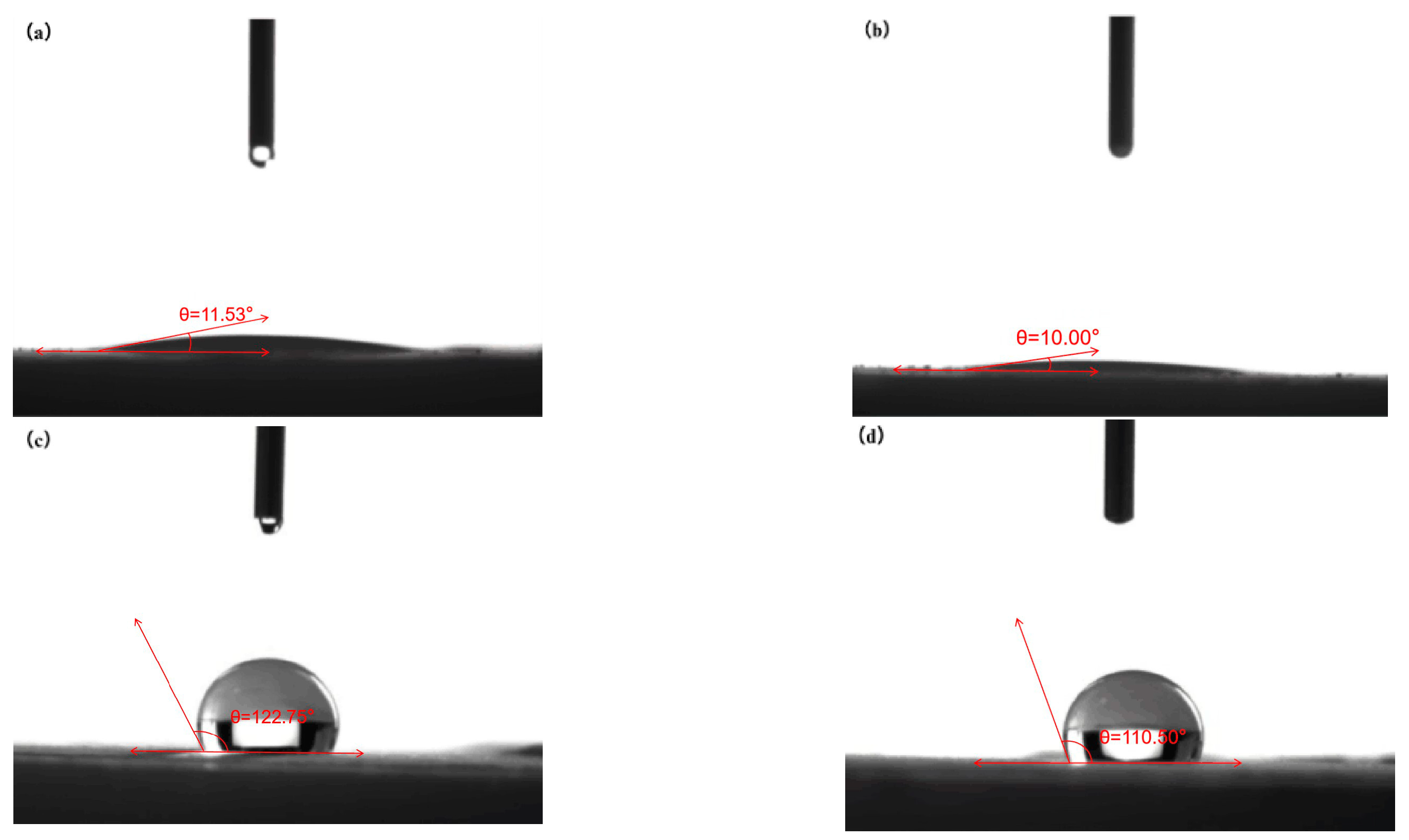
2.2.4. Contact Angle Measurement

The ore sample was dried and pressed into a sheet with a smooth surface, and the contact angle of the distilled water on the sample surface was measured using the sessile drop method. The sample was placed directly on the instrument stage, the droplet was captured by a thin syringe needle through which the liquid was added or withdrawn, and images were recorded using a camera when the droplet touched the surface of the sample. After image acquisition, the subsequent step for contact angle measurement is image processing. The secant method was used in this study; the contact angle readings were measured by adjusting the goniometer as a tangent at the point of the three-phase contact [14].

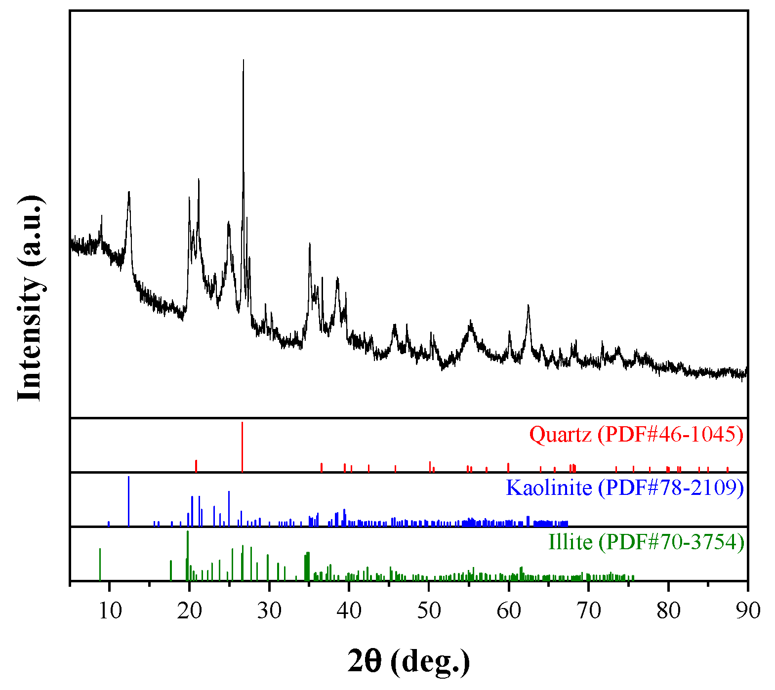
2.2.5. X-ray Diffraction Analysis

A RIG-AKU Rotating Anode XRD system (Rigaku RU-200B, Tokyo, Japan) was used to measure the X-ray diffraction. A copper-target-type X-ray generator was used, and the power of the X-ray tube was set at 40 kV and 110 mA. The scan speed for the continuous mode was 2° per minute. To ascertain the chemical makeup of the mineral samples, a D8 Advance X-ray Diffractometer (Bruker Corporation, Bremen, Germany) was used.

2.2.6. Thermogravimetric Analysis

An STA409PC thermogravimetric analyzer (NETZSCH Scientific Instruments Trading (Shanghai) Ltd., Shanghai, Germany) was used to determine the relationship between sample quality and temperature or time. The heating rate was set to 10 °C/min, the temperature range was set to 30–800 °C, and the data were measured and collected under nitrogen protection.

3. Results and Discussion

3.1. Effect of Ammonium Formate on WREO Leaching Process

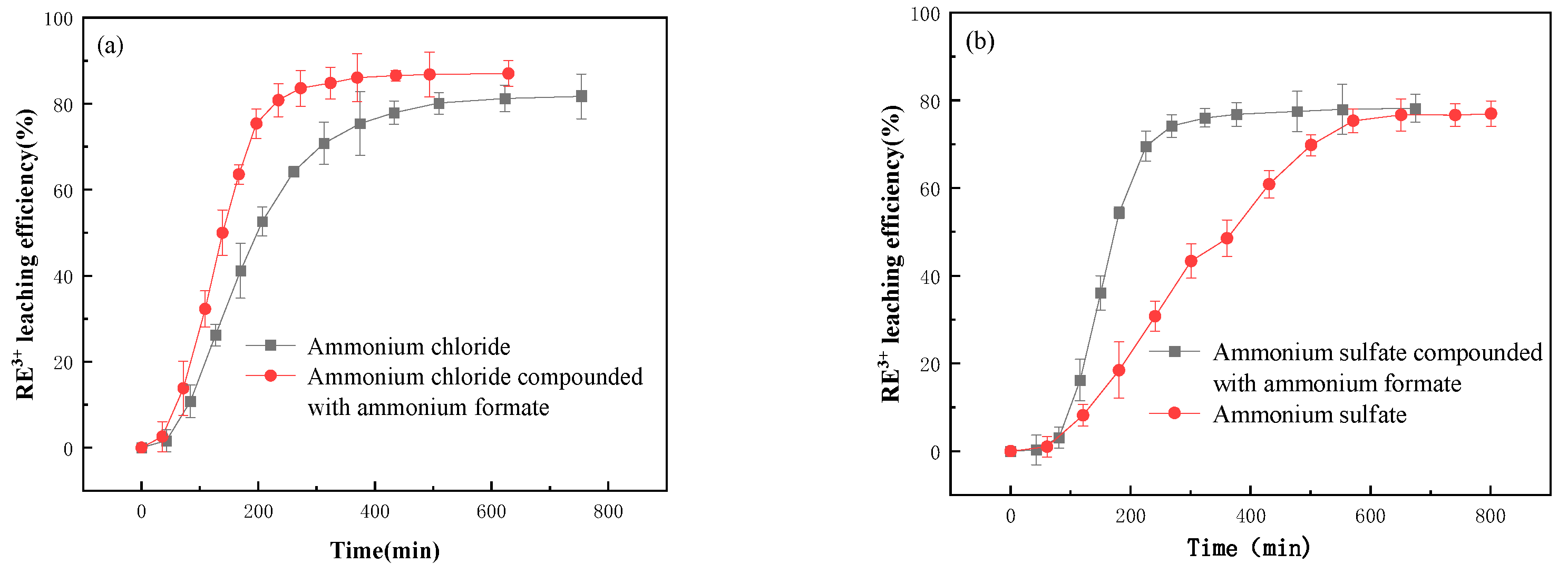
3.1.1. Effect of Ammonium Formate on WREO Leaching Efficiency

In the presence of ammonium formate, the RE3+ leaching efficiency was measured in the leaching system of ammonium chloride and ammonium sulfate where the loading height of WREOs was 6 cm and the solid–liquid ratio was 1:2. The results in Figure 2 show that the RE3+ leaching efficiency increases rapidly with the increase in time until equilibrium is reached. In the ammonium chloride system, the leaching equilibrium times of RE3+ are 510 min and 370 min for ammonium chloride without and with ammonium formate, respectively. The leaching equilibrium time is advanced by 140 min due to the presence of ammonium formate, and the RE3+ leaching efficiency increases from 82% to 87%. In the ammonium sulfate system, the RE3+ leaching equilibrium times are 571 min and 324 min for ammonium sulfate without and with ammonium formate; the RE3+ leaching equilibrium time is advanced by 247 min with the addition of ammonium formate. Compared with the ammonium salt leaching, the addition of ammonium formate results in a significant reduction in the leaching equilibrium time and an increase in the RE3+ leaching efficiency.

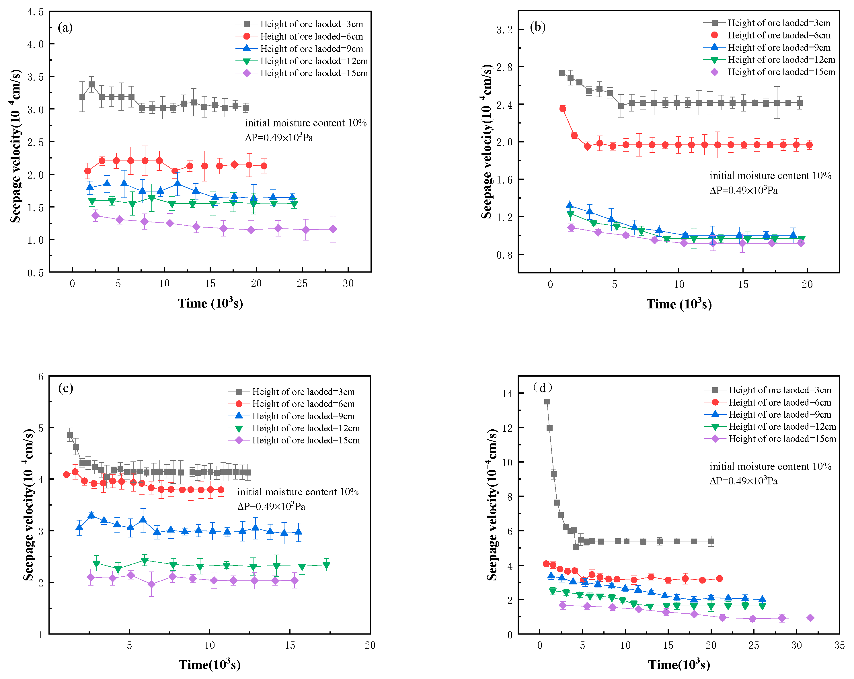
3.1.2. Effect of Ammonium Formate on Seepage

For the condition of 10% initial moisture content and 0.49 × 10³ Pa differential pressure, the change curves of seepage velocity with time for different loading heights are shown in Figure 3. The effects of ammonium formate on the seepage process for the ammonium chloride system and ammonium sulfate system are shown in Table 1 and Table 2.
The penetration process for WREOs with different particle sizes follows Darcy’s law [15], which states that the leach reagent flow (Q) of the solution in the ore body is positively correlated with the cross-sectional area (A) and the hydraulic gradient (J). Q, A and the seepage velocity (v) can be measured through experiments, and the seepage coefficient (k) can be calculated by using the known conditions. The strength of the seepage effect can be judged by comparing the seepage coefficient. If the seepage coefficient increases, the seepage effect is enhanced. The Darcy’s law equation used is as follows:
Q = k A J
v = Q A = k
In the presence of ammonium formate, the time required to reach seepage stabilization was significantly shortened in both systems, and the stable seepage velocity was also increased. Under the conditions of 10% initial moisture content, 0.49 × 10³ Pa differential pressure and 6cm height of ore loaded, the seepage velocity is increased by 1.67 × 10⁻⁴ cm·s−1 and 1.18 × 10⁻⁴ cm·s−1, and the seepage stabilization times are shortened by 5.79 × 10³ s and 1.63 × 10³ s, respectively. This may be due to ammonium formate inhibiting the hydration swelling of WREOs and reducing the thickness of the adsorbed water layer on the surface of mineral particles during the leaching process, thus accelerating the seepage velocity. At the same time, the addition of ammonium formate also increases the initial seepage velocity variation and the stable seepage velocity variation. The reason for this is that the anion in ammonium formate has a stronger complexation ability with rare earth ions, which leads to the improvement of its leaching mass transfer efficiency.

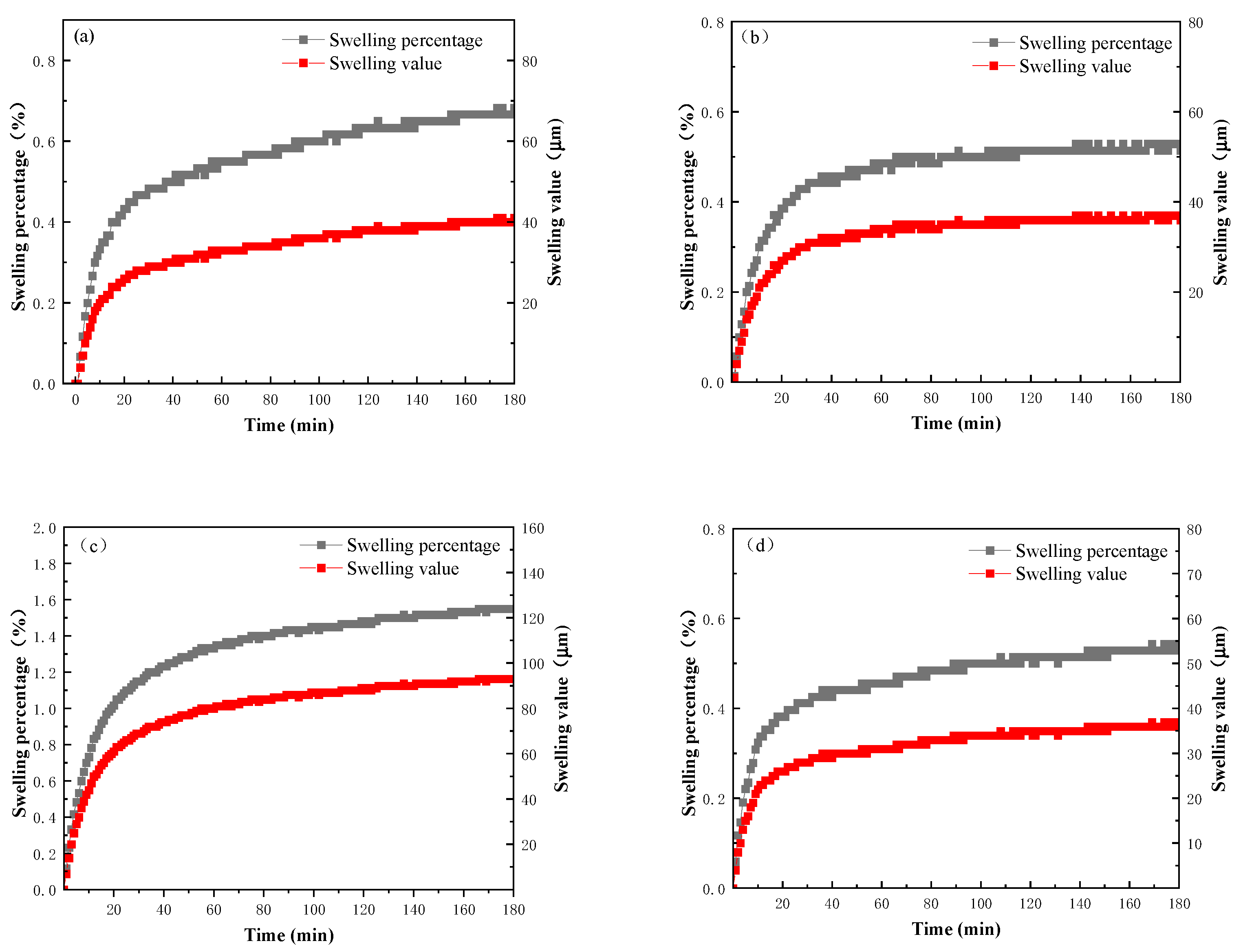
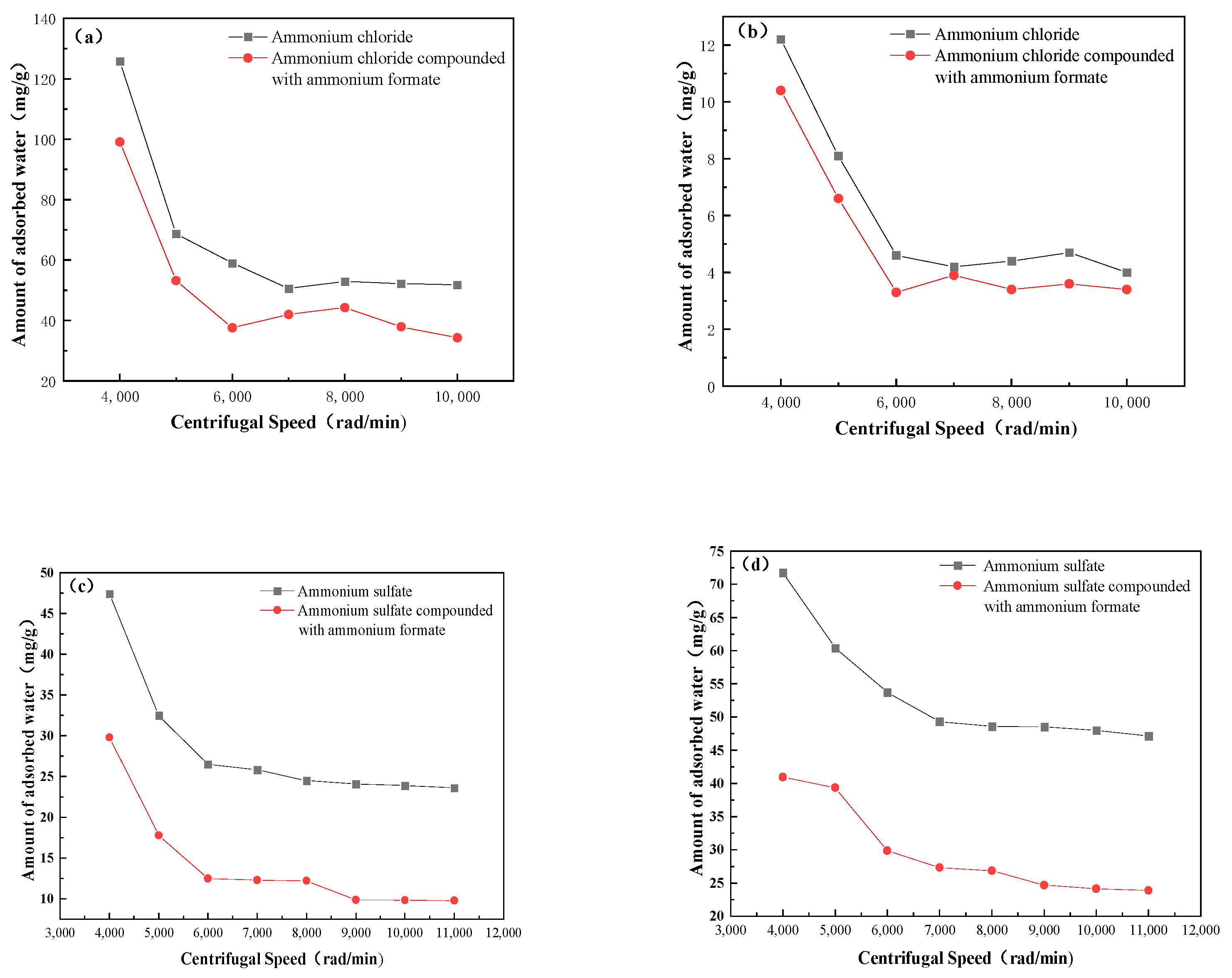
3.1.3. Effect of Ammonium Formate on WREO Swelling

The effect of ammonium formate on the swelling of WREOs is shown in Figure 4. The swelling value of WREOs under the action of ammonium chloride is 41 μm, and the swelling percentage is 0.66%, while the swelling value of WREOs decreases to 37 μm and the swelling percentage is 0.52% in the presence of ammonium formate. The swelling value is reduced by 4 μm, and the swelling percentage is reduced by 0.14%. For the ammonium sulfate leaching, the swelling value of WREOs is 55 μm, and the swelling percentage is 0.91%; with the addition of ammonium formate, the swelling value is 37 μm, and the swelling percentage is 0.54%. The swelling value is reduced by 18 μm, and the swelling percentage is reduced by 0.37%. These results indicate that the ammonium ion in ammonium formate undergoes a complexation reaction with RE3+. The remaining ammonium ions in the solution can effectively inhibit the hydration swelling of clay minerals through a synergistic effect.

3.2. Effect Mechanism of Ammonium Formate during Ammonium Leaching of WREOs

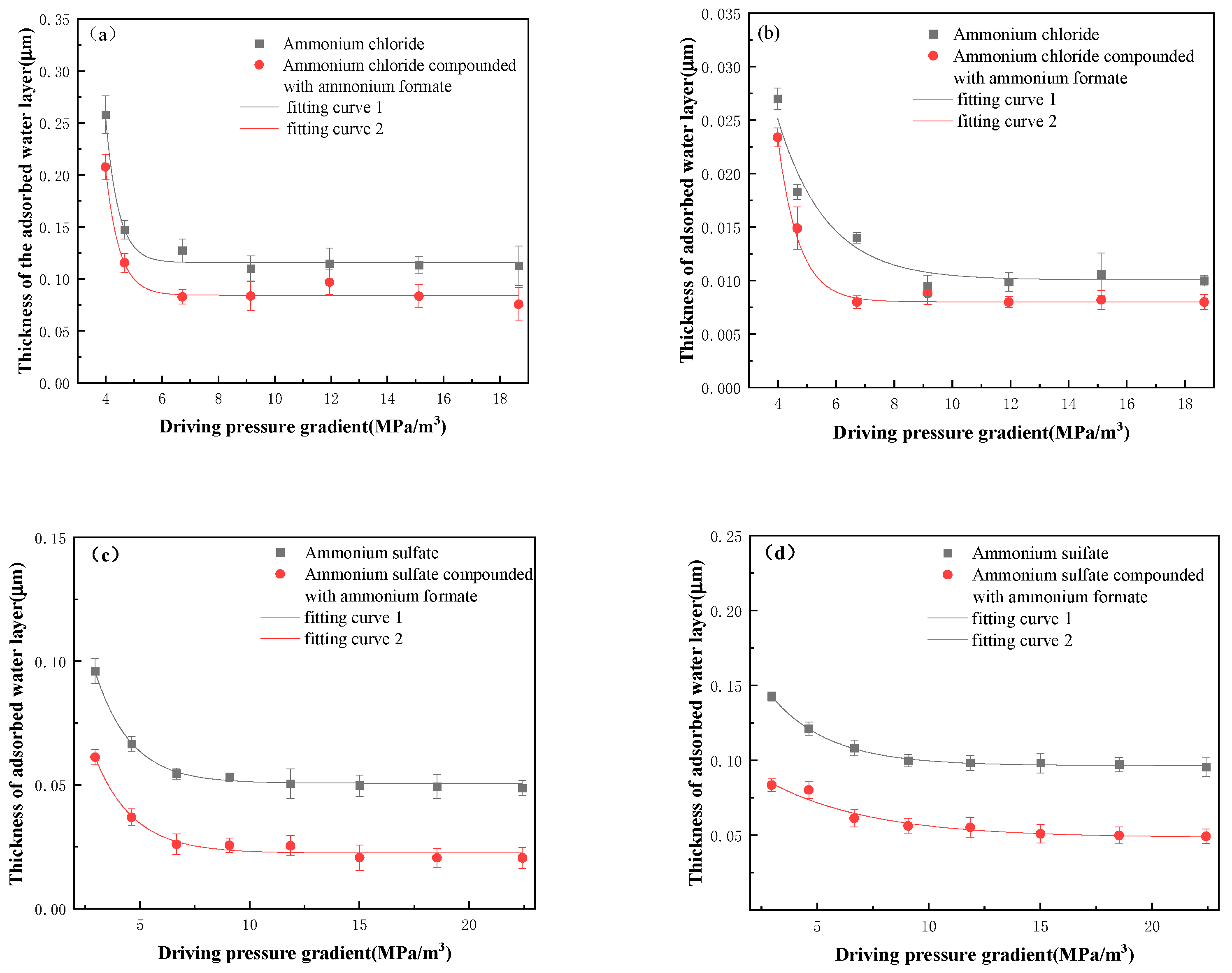
3.2.1. Thickness of the Adsorbed Water Layer on the Clay Mineral Surface
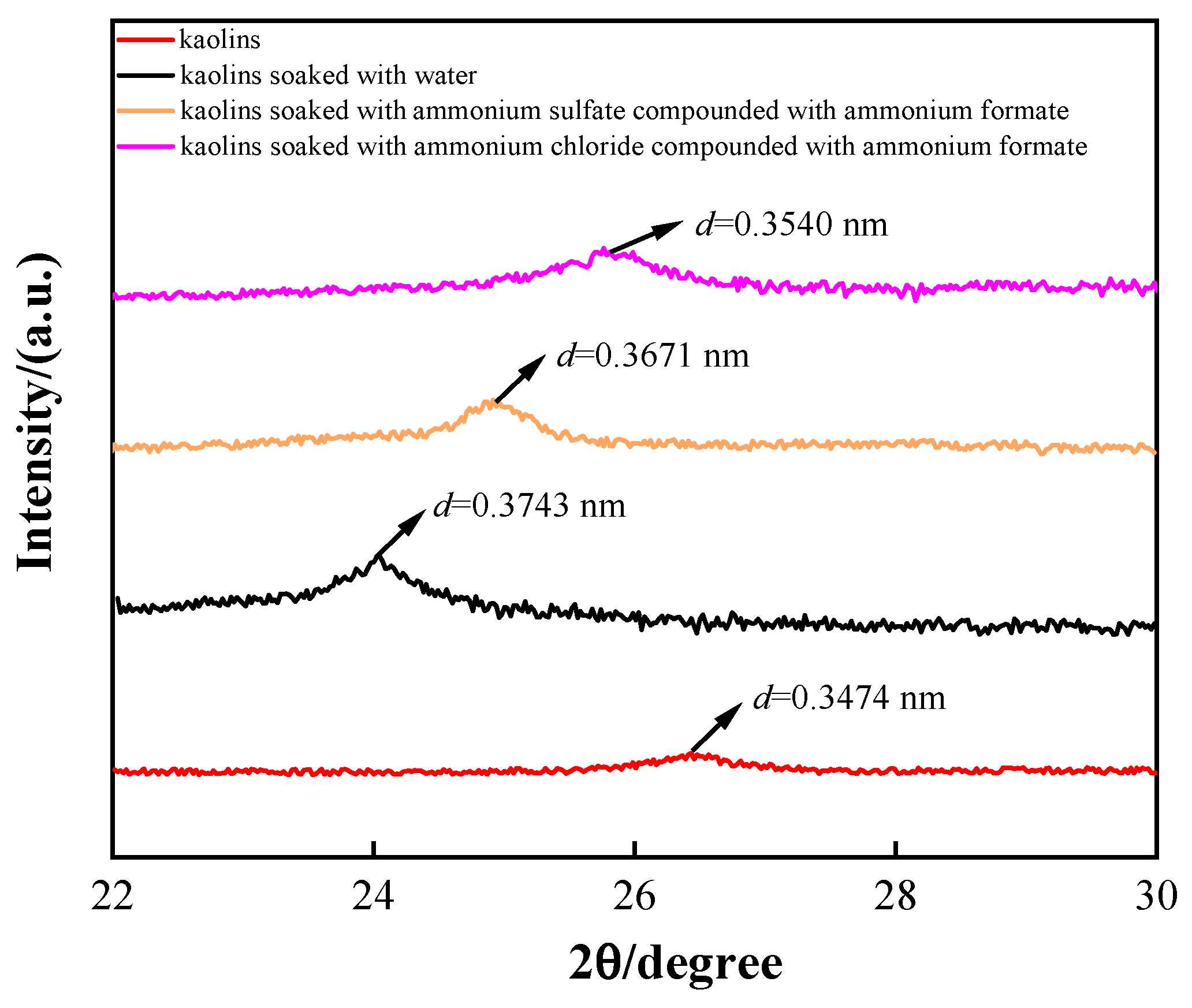
During the leaching process, water molecules react with minerals to form hydrates, and a water film is formed on the surface of mineral particles; i.e., hydration occurs [16]. Hydration will cause a reduction in pores among mineral particles, further reducing the leaching efficiency. Therefore, the thickness of the surface water layer was measured to reflect the degree of hydration to discuss the promotion mechanism of ammonium formate in the WREO leaching process.
Clay minerals have a naturally hydrophilic surface. When clay minerals are soaked with a solution to reach adsorption saturation, a water film will be formed on the mineral surface. After the clay minerals are dewatered by using a centrifuge, the remaining water on the mineral surface contains the retained water and the adsorbed water. In this study, clay minerals were modified to form a hydrophobic surface. After soaking and dewatering, the water on the mineral surface is approximated as the retained water. After dewatering for both unmodified and modified clay minerals, the weight differentiation is recognized as the adsorbed water. Therefore, the modified experiment was used to measure the amount of adsorbed water, and the thickness of the absorbed water layer was further calculated.
Figure 1 shows that the content of kaolin and illite is relatively high in WREOs, so they are used as representatives to study the effect of ammonium formate on the thickness of the surface water layer of the WREOs in this study. The method of coupling agent modification was adopted in this study. First, 5 g of illite or kaolin was mixed with 1 g of silane coupling agent KH-570 and 2 g of ethanol. The reaction was then conducted in the flask with 200 mL distilled water as the reaction environment for 2 h and 1 h at 70 °C and 80 °C, respectively. The two modified clay minerals were obtained, and the contact angle was measured to judge if it had changed from hydrophilic to hydrophobic, as illustrated in Figure 5. The contact angles of kaolin and illite before modification were 11.53° and 10.00°, respectively, indicating that they were hydrophilic, and their surface would have a strong effect on water molecules when in contact with water. After modification, the hydrophobic nature of the clay minerals was confirmed by the contact angles of kaolin and illite, which were 122.75° and 110.50°, respectively. The silane coupling agent KH-570 contains hydrophilic and hydrophobic groups after hydrolysis. The hydrophilic end of the silane coupling agent reacts with the reactive group on the surface of clay minerals to form hydrogen bonds, which then condense into covalent bonds. The hydrophobic group at the other end combines with polymer molecules to achieve the purpose of modification, causing the clay minerals to change from hydrophilic to hydrophobic.
Before and after modification, kaolin and illite were soaked in ammonium chloride, ammonium sulfate, ammonium chloride compounded with ammonium formate and ammonium sulfate compounded with ammonium formate solution for 24 h to reach adsorption saturation and then centrifuged at different speeds. The water in the sliding layer was detached from the particle surface because of the action of driving pressure on the sliding layer on the clay mineral particle surface. The weight of the adsorbed water layer on the surface of clay mineral particles under different driving pressures was determined, and the thickness of the adsorbed water layer was calculated using the relationship between the particle volume increment, density and the amount of adsorbed water. The equation is as follows:
δ G = [ ( A · ρ B + ρ W ρ W ) 1 3 1 ] · r
where δ G is the thickness of adsorbed water layer, μm; A is the adsorbed water content of clay mineral particles per unit weight, g/g; ρB and ρW are the densities of clay mineral particles and distilled water, respectively, g/cm3; and r is the geometric mean of the radius of the clay mineral particles, μm.
The relationship between the amount of adsorbed water on the clay mineral surface and the centrifugal speed was calculated and is shown in Figure 6. In comparison with clay minerals soaked in ammonium chloride and ammonium sulfate without ammonium formate, the adsorbed water on clay minerals soaked in ammonium salts with ammonium formate significantly decreases. The weight of adsorbed water gradually decreases with the increase in centrifugal speed and force. This suggests that ammonium formate can obviously reduce the adsorbed water on the clay mineral particle surface. Ammonium formate can reduce the amount of adsorbed water by weakening the force of electrostatic attraction or hydrogen bonding between clay mineral particles and water molecules.
The water layer on the mineral particle surface can increase the volume of mineral particles and reduce the volume of intergranular spaces. In addition, the leaching solution can be absorbed to prevent seepage and diffusion [17]. The thickness variation of the adsorbed water layer with the driving pressure gradient in the ammonium salt leaching system was analyzed. The centrifugal speed was then translated into the driving pressure gradient using the following equation:
G = ρ ω 2 [ ( R + L ) 2 R 2 ] 2 L × 9.81 × 10 6
P = G × L
where G is the driving pressure gradient, MPa/m; ω is the rotational angular velocity, rad/s; L is the pattern length, m; R is the radius, m; ρ is the density of the fluid medium, kg/m3; and p is the driving pressure, MPa. L = 0.109 m, R = 0.0215 m and the different centrifugal speeds are calculated using the equation. The corresponding driving pressure and driving pressure gradient are shown in Table 3. The data in Table 3 were fitted to obtain a curve showing the variation in the thickness of the adsorbed water layer with the driving pressure gradient, and the results are shown in Figure 7.
According to the Stern model in the theory of colloid chemistry, Equation (6) can be obtained.
δ G = δ s + δ a
where δ G is the thickness of the adsorbed water layer on the particle surface, μm; δ s is the thickness of the Stern layer, μm; and δ a is the thickness of the sliding layer, μm.
Due to the electrostatic interaction and van der Waals attraction between the particle surface and water molecules, the Stern layer on the particle surface is tightly adsorbed on the solid particle surface. The sliding layer is related to the external environment of the particle, and it is related to the driving pressure gradient in this study.
δ a = aexp ( bG )
where a and b are constants related to the properties of clay mineral particles and fluids; G is the driving pressure gradient, MPa/m.
The relationship between the thickness of the adsorbed water layer of clay mineral particles and the driving pressure gradient is obtained by combining Equations (6) and (7):
δ G = δ s + aexp ( bG )
The experimental data in Figure 7 were put into Equation (8) to obtain the empirical equations of the adsorbed water layer thickness on kaolin and illite particle surfaces and the driving pressure gradient. The results are as follows:
δ G 1   =   0.1155   +   859.265 exp ( 2.1832 G )
δ G 2   =   0.0845   +   413.329 exp ( 2.0366 G )
δ G 3   =   0.0102   +   0.4043 exp ( 0.8068 G )
δ G 4   =   0.0081   +   2.1499 exp ( 1.2398 G )
δ G 5   =   0.0498   +   0.2692 exp ( 0.5957 G )
δ G 6   =   0.0219   +   0.2064 exp ( 0.5617 G )
δ G 7   =   0.0219   +   0.2064 exp ( 0.5617 G )
δ G 8   =   0.0951   +   0.1575 exp ( 0.3316 G )
The above equations also show that the adsorbed water layer will gradually decrease with the increase in driving pressure until it reaches equilibrium, demonstrating the process of the adsorbed water layer gradually falling off under the influence of external forces. When the weight and the thickness of the water layer do not change, the water layer on the modified clay mineral particle surface is only composed of the retained water layer, so the calculated thickness of the water layer is the thickness of the adsorbed water layer. In the analysis of the thickness of adsorbed water layer under the action of various leaching solutions, the results show that ammonium formate effectively reduces the thickness of adsorbed water layer by 0.0501 μm and 0.0280 μm for kaolin in the ammonium chloride system and ammonium sulfate system, respectively, while for illite, the thickness of adsorbed water layer is reduced by 0.0020 μm and 0.0282 μm. The addition of ammonium formate significantly reduced the layer thickness on the clay mineral particle surface, effectively inhibiting hydration and increasing the seepage velocity.

3.2.2. XRD

The XRD pattern results for original kaolin, water-soaked kaolin, kaolin soaked with ammonium chloride compounded with ammonium formate and kaolin soaked with ammonium sulfate compounded with ammonium formate are shown in Figure 8; the interlayer distance (d) was calculated using the following Bragg equation:
2 d sin θ = n λ
where d is the crystal plane spacing, θ is the diffraction angle, n is the diffraction order and λ is the diffraction wavelength (0.154 nm).
As seen in Equation (17), the smaller the diffraction angle is, the larger the interlayer spacing is. The interlayer spacing and d-spacing of different samples were calculated using Equation (17). Figure 8 shows that the interlayer spacing of kaolin is the smallest. After soaking in water, the diffraction peak angle moves to a lower angle, and the interlayer spacing increases to 0.3743 nm. After soaking in a compound solution of ammonium chloride and ammonium formate, the d-spacing of kaolin increases to 0.3540 nm. It increases to 0.3671 nm after soaking in a compound solution of ammonium sulfate and ammonium formate. Compared with soaking in water, the interlayer spacing of kaolin soaked in the compound solutions slightly decreased by 0.0203 nm and 0.0072 nm, respectively, indicating that the addition of ammonium formate made the interlayer spacing of kaolin thinner. The amount of absorbed water decreased due to the smaller interlayer spacing, thereby reducing the thickness of the adsorbed water layer.

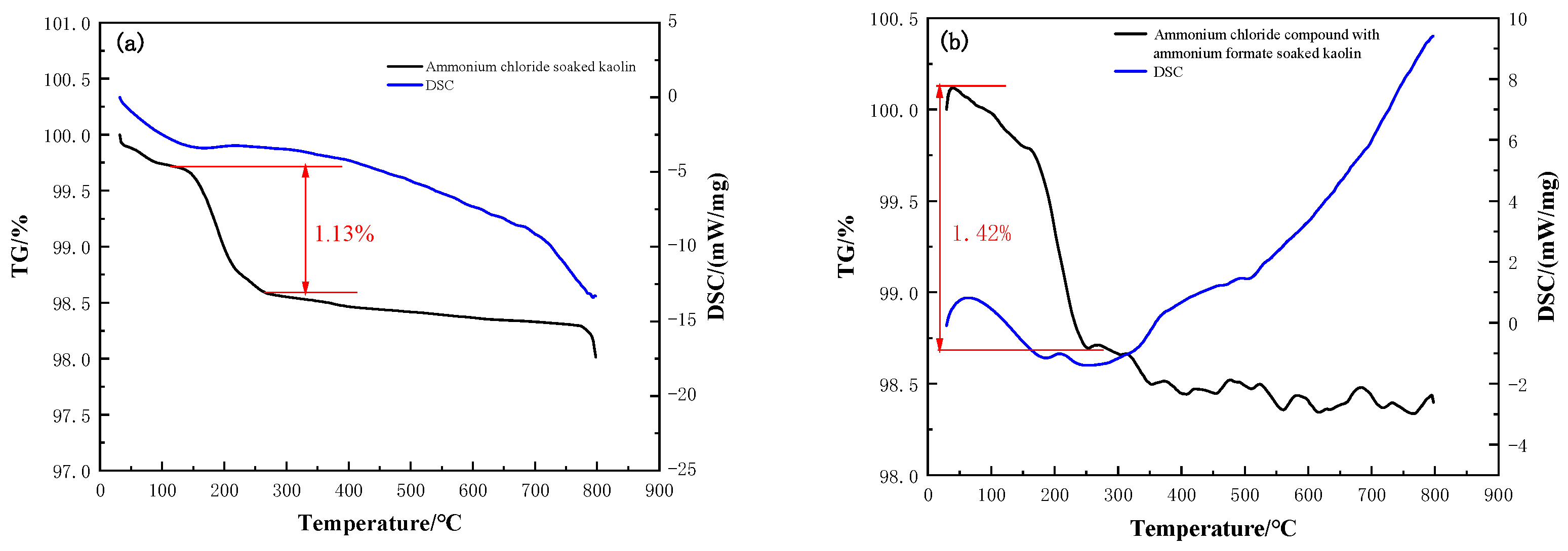
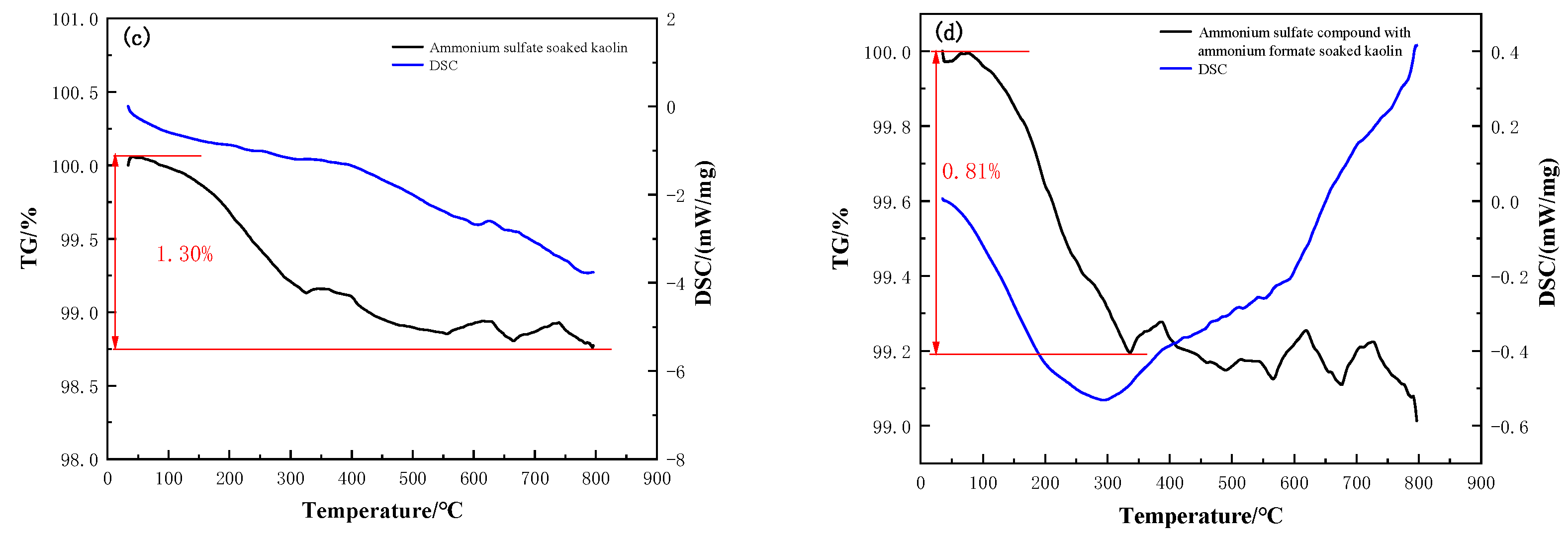
3.2.3. Thermogravimetric Analysis of Clay Minerals

Clay minerals contained in WREOs mainly include kaolin and illite, both of which are layered silicates with similar structures and properties. Kaolin was selected for thermogravimetric analysis in this study. Thermogravimetric analysis of kaolin was carried out under different conditions, and the results are shown in Figure 9.
As seen in Figure 9, the TG curve of kaolin first shows a sharp decrease with the increase in temperature and then is flattened with the further increase in temperature to a certain level. The specific gravity of the ore sample gently decreases in the range of 30–150 °C and then sharply declines by 1.13% in the range of 150–250 °C. The DSC curve drops smoothly, indicating that the structure of kaolin has not changed at this time. The DSC curve of kaolin samples soaked in ammonium chloride and in ammonium chloride with ammonium formate were compared. The DSC curve of samples changed after the addition of ammonium formate; it began to rise at 265 °C, which means the changes in the structure happen due to the action of ammonium formate. As seen in Figure 9c, the specific gravity decreases by 1.30% in the range of 30–800 °C, and the DSC curve smoothly slides down, which means the kaolin structure does not change. Compared with the variation in the DSC curve shown in Figure 9c, the DSC curve in Figure 9d shows an obvious rise at 300 °C. Consequently, the addition of ammonium formate results in a reduction in the amount of adsorbed water and then is conducive to inhibiting the swelling of clay minerals.

4. Conclusions

In an ammonium salt system, the presence of ammonium formate can improve the rare earth leaching efficiency and shorten the leaching equilibrium time. In order to explore the influence of ammonium formate on WREO leaching, the effects of ammonium formate on the seepage, leaching and swelling of WREOs under an ammonium salt system were investigated in this study. The promotion mechanism of ammonium formate was demonstrated on the basis of the thickness of the adsorbed water layer and XRD and thermogravimetric analysis. When ammonium formate was added to the ammonium chloride system and ammonium sulfate system, the leaching equilibrium times were shortened by 140 min and 247 min, respectively. Under the conditions of 10% initial moisture content, 0.49 × 10³ Pa differential pressure and 6 cm height of ore loaded, the seepage velocity was increased by 1.67 × 10⁻⁴ cm·s−1 and 1.18 × 10⁻⁴ cm·s−1, and the seepage stabilization times were shortened by 5.79 × 10³ s and 1.63 × 10³ s, respectively. In the presence of ammonium formate, the swelling values of WREOs were reduced by 4 μm and 18 μm, and the swelling percentages fell by 0.14% and 0.37% in the ammonium chloride system and ammonium sulfate system, respectively. Kaolin and illite were modified to measure the thickness of adsorbed water layer, the results demonstrate that ammonium formate effectively reduced the thickness of adsorbed water layer by 0.0501 μm and 0.0280 μm for kaolin in the ammonium chloride system and ammonium sulfate system, respectively, while for illite, the thickness of adsorbed water layer was reduced by 0.0020 μm and 0.0282 μm. The XRD results show that compared with soaking in water, the interlayer spacing of kaolin soaked in the compound solutions slightly decreased by 0.0203 nm and 0.0072 nm, respectively. The decreased interlayer spacing of clay minerals after soaking in an ammonium formate solution indicates an inhibiting effect of ammonium formate on the hydration of clay minerals. The thermogravimetric results directly demonstrate that ammonium formate decreases the amount of absorbed water on clay minerals.

Author Contributions

Conceptualization, R.C. and F.Z.; methodology, R.C. and F.Z.; software, Y.M.; validation, F.Z. and D.Z.; formal analysis, F.Z.; investigation, Q.Z.; resources, F.Z.; data curation, X.G. and Y.M.; writing—original draft preparation, X.G. and Y.M.; writing—review and editing, F.Z.; supervision, F.Z. and J.Y.; project administration, F.Z. All authors have read and agreed to the published version of the manuscript.

Funding

This research was funded by National Natural Science Foundation of China (22078252, 52274266, 51874212).

Data Availability Statement

No new data were created or analyzed in this study. Data sharing is not applicable to this article.

Acknowledgments

Financial support for this work from the National Natural Science Foundation of China (22078252, 52274266, 51874212) and the Young Top-notch Talent Cultivation Program of Hubei Province is greatly appreciated.

Conflicts of Interest

The authors declare no conflict of interest.

References

  1. Moldoveanu, G.A.; Papangelakis, V.G. Recovery of rare earth elements adsorbed on clay minerals: I. Desorption mechanism. Hydrometallurgy 2012, 117, 71–78. [Google Scholar] [CrossRef]
  2. Ruan, C.; Yunhui, Z.; Meisheng, Y. Comparison on extraction of ion type rare earth with three eluents. Chem. Eng. Equip. 1987, 1987, 41–45. [Google Scholar]
  3. Jun, T.; Chi, R.-A.; Yin, J.-Q. Leaching process of rare earths from weathered crust elution-deposited rare earth ore. Trans. Nonferrous Met. Soc. China 2010, 20, 892–896. [Google Scholar]
  4. Xiao, Y.; Feng, Z.; Hu, G.; Huang, L.; Huang, X.; Chen, Y.; Long, Z. Reduction leaching of rare earth from ion-adsorption type rare earths ore with ferrous sulfate. J. Rare Earths 2016, 34, 917–923. [Google Scholar] [CrossRef]
  5. Xiao, Y.; Feng, Z.; Huang, X.; Huang, L.; Chen, Y.; Wang, L.; Long, Z. Recovery of rare earths from weathered crust elution-deposited rare earth ore without ammonia-nitrogen pollution: I. leaching with magnesium sulfate. Hydrometallurgy 2015, 153, 58–65. [Google Scholar]
  6. Rao, Y.; Zhang, X.; Gao, Z.; Xiang, R.; Zhang, L. Experimental Study on Pore Structure and Soil-Water Characteristic Curve of Ionic Rare Earth Ore under Seepage. Minerals 2023, 13, 1035. [Google Scholar] [CrossRef]
  7. Deng, Y.; Wan, Y.; Yu, H.; Kang, S.; Deng, Y.; Yang, J. Changes in Microfine Particle Migration of Ionic Rare Earth Ores during Leaching. Sustainability 2023, 15, 3867. [Google Scholar] [CrossRef]
  8. Zhang, Z.; Li, H.; Long, F.; Chi, X.; Chen, W.; Chen, Z. Inhibition on the swelling of clay minerals in the leaching process of weathered crust elution-deposited rare earth ores. Appl. Clay Sci. 2022, 216, 106362. [Google Scholar] [CrossRef]
  9. Norrish, K.J. The swelling of montmorillonite. Discuss. Faraday Soc. 1954, 18, 120–134. [Google Scholar] [CrossRef]
  10. Zhou, F.; Zhang, L.; Wang, Z.; Zhang, Y.; Wu, X. Application of surfactant for improving leaching process of weathered crust elution-deposited rare earth ores. J. Rare Earths 2022, in press. [CrossRef]
  11. Feng, J.; Zhou, F.; Chi, R.; Liu, X.; Xu, Y.; Liu, Q. Effect of a novel compound on leaching process of weathered crust elution-deposited rare earth ore. Miner. Eng. 2018, 129, 63–70. [Google Scholar] [CrossRef]
  12. Zhengyan, H.; Zhang, Z.; Junxia, Y.; Zhigao, X.; Ru’an, C. Process optimization of rare earth and aluminum leaching from weathered crust elution-deposited rare earth ore with compound ammonium salts. J. Rare Earths 2016, 34, 413–419. [Google Scholar]
  13. He, Z.; Zhang, Z.; Yu, J.; Zhou, F.; Xu, Y.; Xu, Z.; Chen, Z.; Chi, R. Kinetics of column leaching of rare earth and aluminum from weathered crust elution-deposited rare earth ore with ammonium salt solutions. Hydrometallurgy 2016, 163, 33–39. [Google Scholar] [CrossRef]
  14. Akbari, R.; Antonini, C.J.; Science, I. Contact angle measurements: From existing methods to an open-source tool. Adv. Colloid Interface Sci. 2021, 294, 102470. [Google Scholar] [CrossRef] [PubMed]
  15. Jun, T.; Ruan, C.; Guocai, Z.; Shengming, X.; Xin, Q.; China, Z.Z. Leaching hydrodynamics of weathered elution-deposited rare earth ore. Trans. Nonferrous Met. Soc. China 2001, 3, 434–437. [Google Scholar]
  16. Gruen, D.W.; Marčelja, S. Spatially varying polarization in water. A model for the electric double layer and the hydration force. J. Chem. Soc. Faraday Trans. 2 Mol. Chem. Phys. 1983, 79, 225–242. [Google Scholar] [CrossRef]
  17. Ye, H.; Gao, X.; Wang, R.; Wang, H.J.C. Relationship among particle characteristic, water film thickness and flowability of fresh paste containing different mineral admixtures. Constr. Build. Mater. 2017, 153, 193–201. [Google Scholar] [CrossRef]
Figure 1. XRD of WREOs.
Minerals 13 01286 g001
Figure 2. RE3+ leaching efficiency as a function of time. (a) Ammonium chloride system; (b) ammonium sulfate system.
Minerals 13 01286 g002
Figure 3. Seepage velocity as a function of time. (a) Ammonium chloride; (b) ammonium sulfate; (c) ammonium chloride compounded with ammonium formate; (d) ammonium sulfate compounded with ammonium formate.
Minerals 13 01286 g003
Figure 4. Swelling percentage and swelling value in different solutions as a function of time. (a) Ammonium chloride; (b) ammonium chloride compounded with ammonium formate; (c) ammonium sulfate; (d) ammonium sulfate compounded with ammonium formate.
Minerals 13 01286 g004
Figure 5. Contact angle of clay minerals in contact with water. (a) Unmodified kaolin; (b) unmodified illite; (c) modified kaolin; (d) modified illite.
Minerals 13 01286 g005
Figure 6. Amount of adsorbed water on clay mineral particle surface under different centrifugal speeds. (a) Kaolin; (b) illite; (c) kaolin; (d) illite.
Minerals 13 01286 g006
Figure 7. Thickness of the adsorbed water layer on the clay mineral particle surface under different driving pressures. (a) Kaolin; (b) illite; (c) kaolin; (d) illite.
Minerals 13 01286 g007
Figure 8. XRD of kaolin in various solutions.
Minerals 13 01286 g008
Figure 9. TG and DTG curves of (a) kaolin soaked in ammonium chloride, (b) kaolin soaked in ammonium chloride compounded with ammonium formate, (c) kaolin soaked in ammonium sulfate and (d) kaolin soaked in ammonium sulfate compounded with ammonium formate.
Minerals 13 01286 g009aMinerals 13 01286 g009b
Table 1. Effect of ammonium formate on seepage process under ammonium chloride system.
Leaching SolutionStabilization Time, 103 sInitial Seepage Velocity, 10−4 cm·s−1Stable Seepage Velocity, 10−4 cm·s−1Initial Seepage Velocity Variation, 10−4 cm·s−1Stable Seepage Velocity Variation, 10−4 cm·s−1
Ammonium chloride12.782.212.13−0.98−0.89
Ammonium chloride compounded with ammonium formate6.994.093.80−0.77−0.34
Table 2. Effect of ammonium formate on the seepage process under ammonium sulfate system.
Leaching SolutionStabilization Time, 103 sInitial Seepage Velocity, 10−4 cm·s−1Stable Seepage Velocity, 10−4 cm·s−1Initial Seepage Velocity Variation, 10−4 cm·s−1Stable Seepage Velocity Variation, 10−4 cm·s−1
Ammonium sulfate6.722.351.97−0.39−0.50
Ammonium sulfate compounded with ammonium formate5.094.083.15−9.43−2.26
Table 3. Different speeds with corresponding driving pressures and driving pressure gradients.
Centrifugal Speed, r/min Driving Pressure Gradient, MPa/mDriving Pressure, MPa
40002.9870.329
50004.6670.513
60006.7200.739
70009.1471.006
800011.9461.314
900015.1201.663
10,00018.6662.053
11,00022.5862.485
Disclaimer/Publisher’s Note: The statements, opinions and data contained in all publications are solely those of the individual author(s) and contributor(s) and not of MDPI and/or the editor(s). MDPI and/or the editor(s) disclaim responsibility for any injury to people or property resulting from any ideas, methods, instructions or products referred to in the content.

