
CO2 Curing of Ca-Rich Fly Ashes to Produce Cement-Free Building Materials


Abstract
:1. Introduction
2. Materials and Methods
2.1. Materials
2.2. Characterization of Materials (Initial and Compacts)
2.2.1. Physical Characterization
2.2.2. Chemical Characterization
2.3. Sample Preparation and Carbonation Apparatus
3. Results
3.1. Variables Affecting CO2 Uptake and Compressive Strength
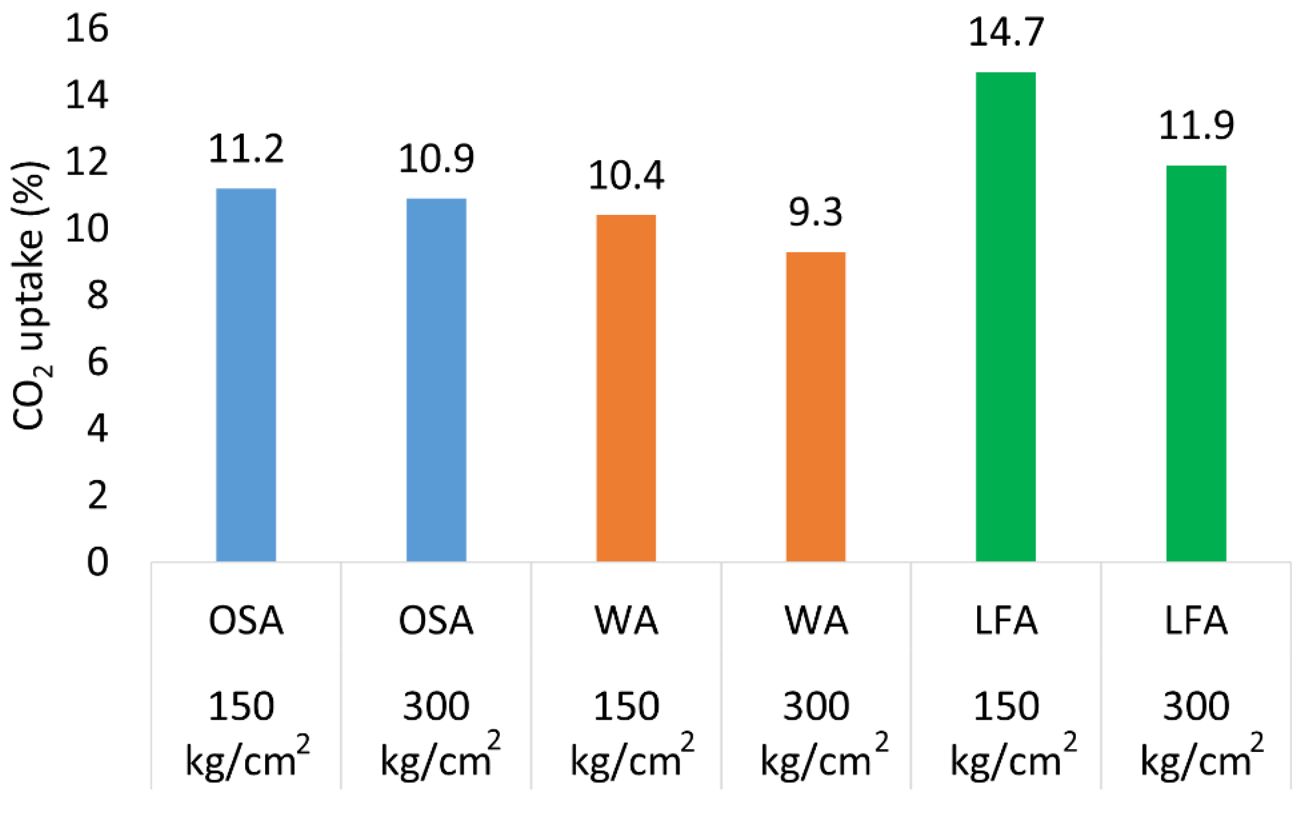
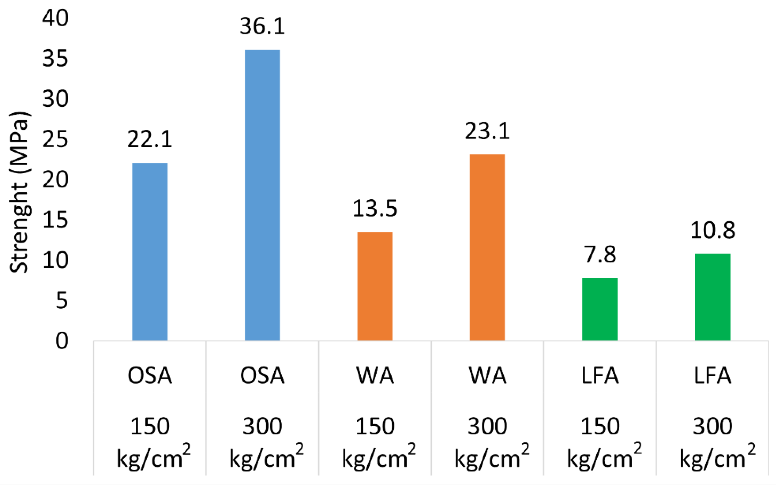
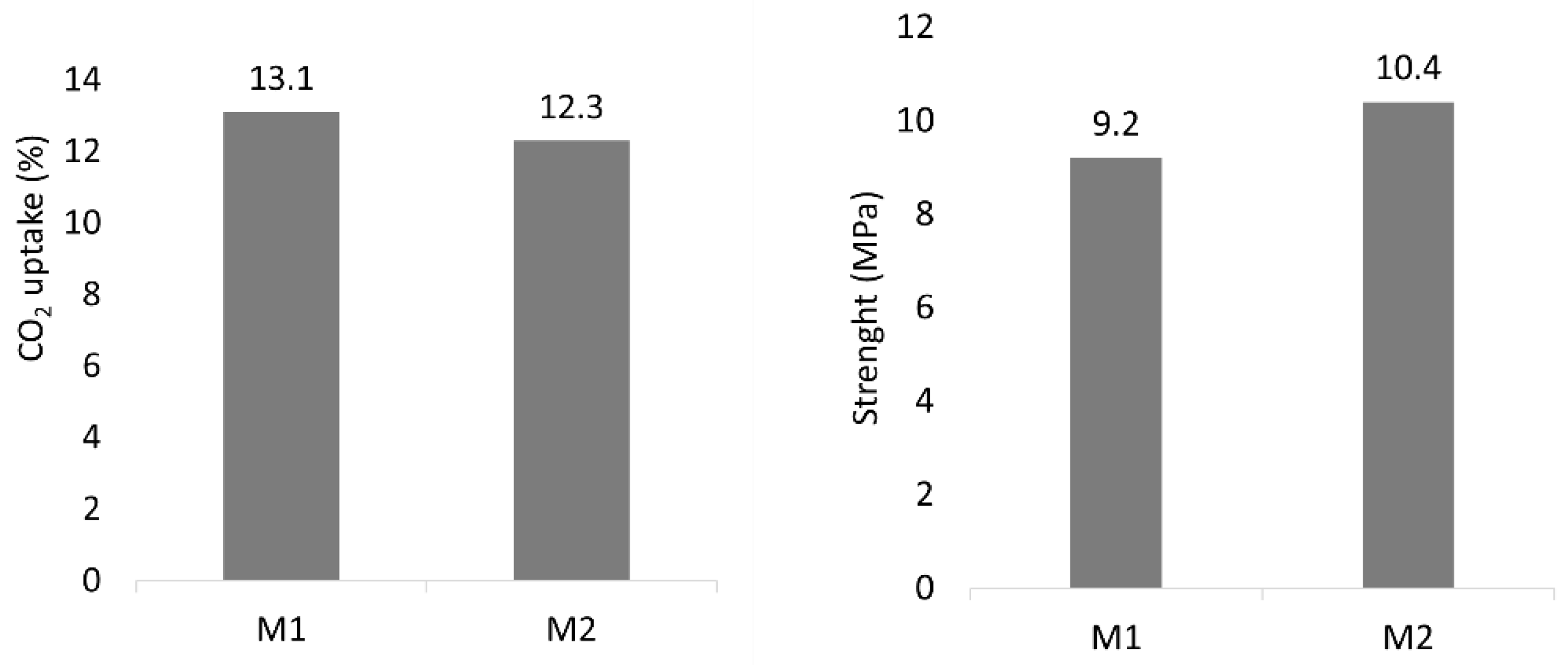
3.1.1. Compaction Pressure and Mix Design
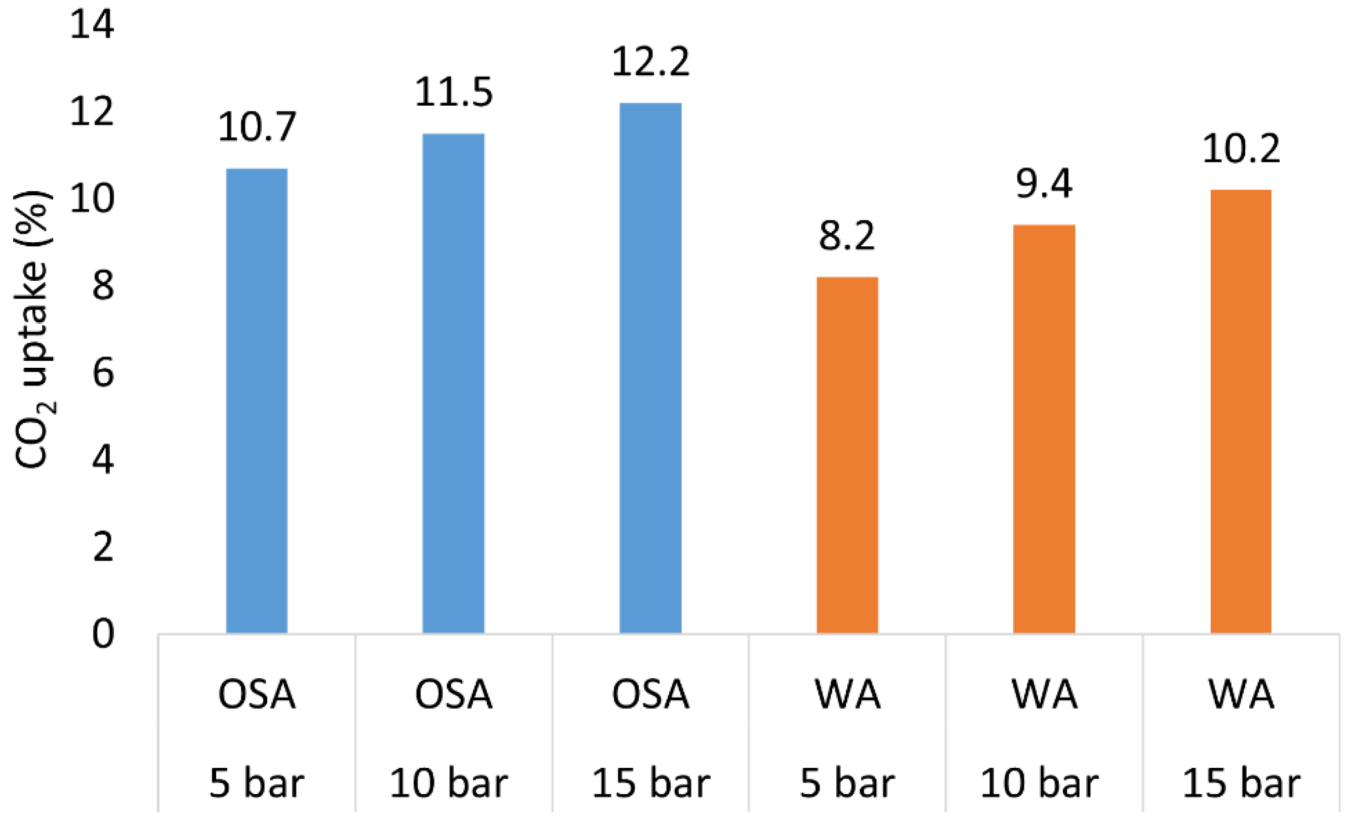
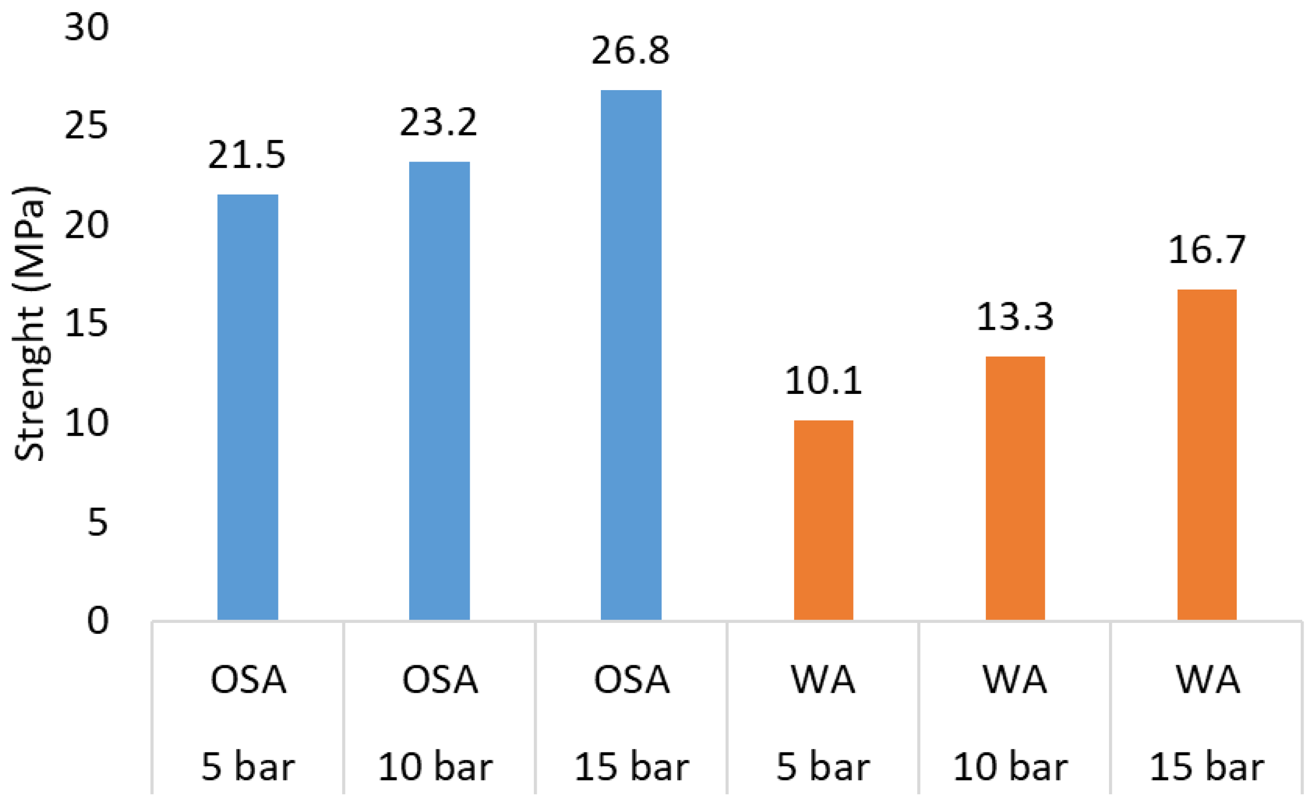
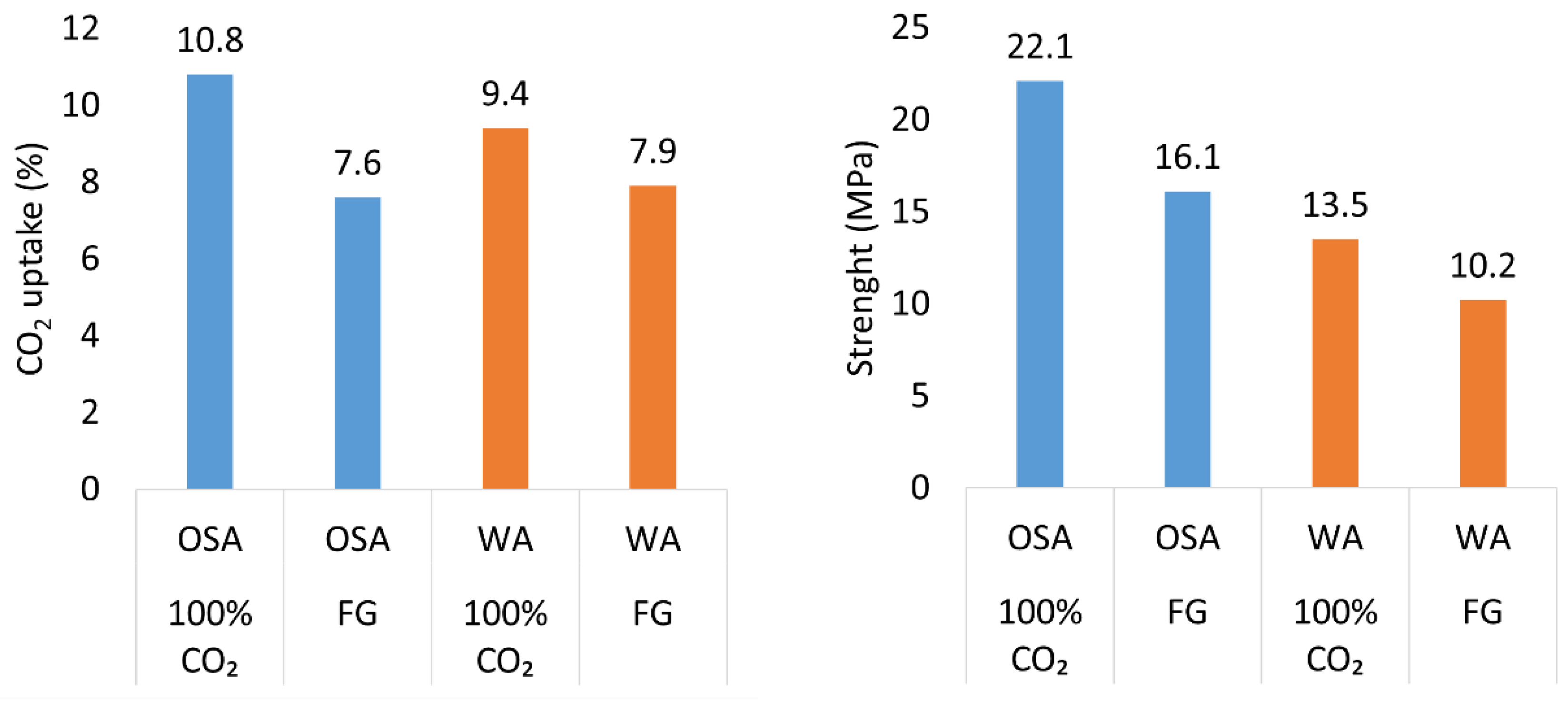
3.1.2. Gas Pressure and CO2 Concentration
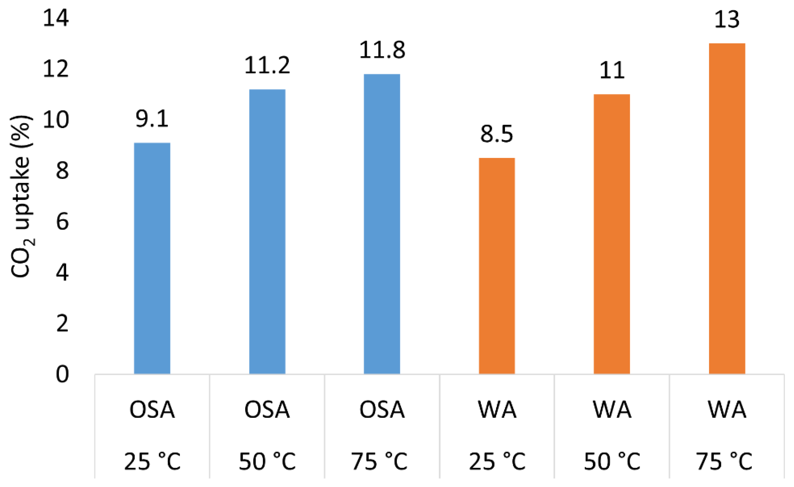
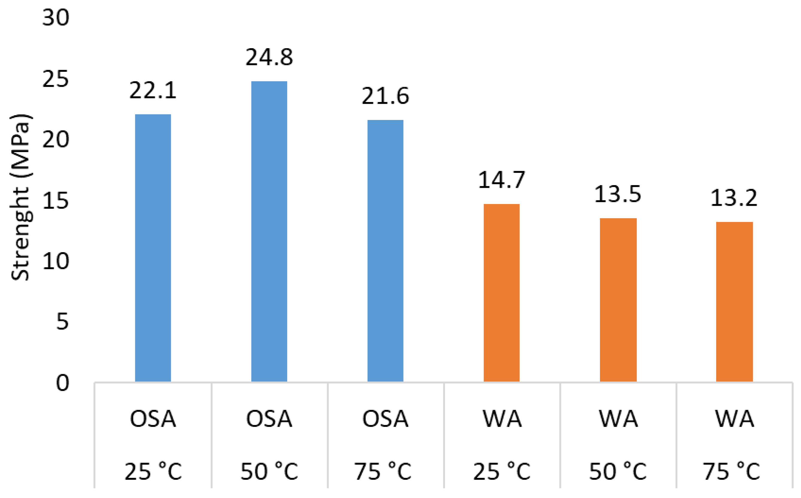
3.1.3. Temperature
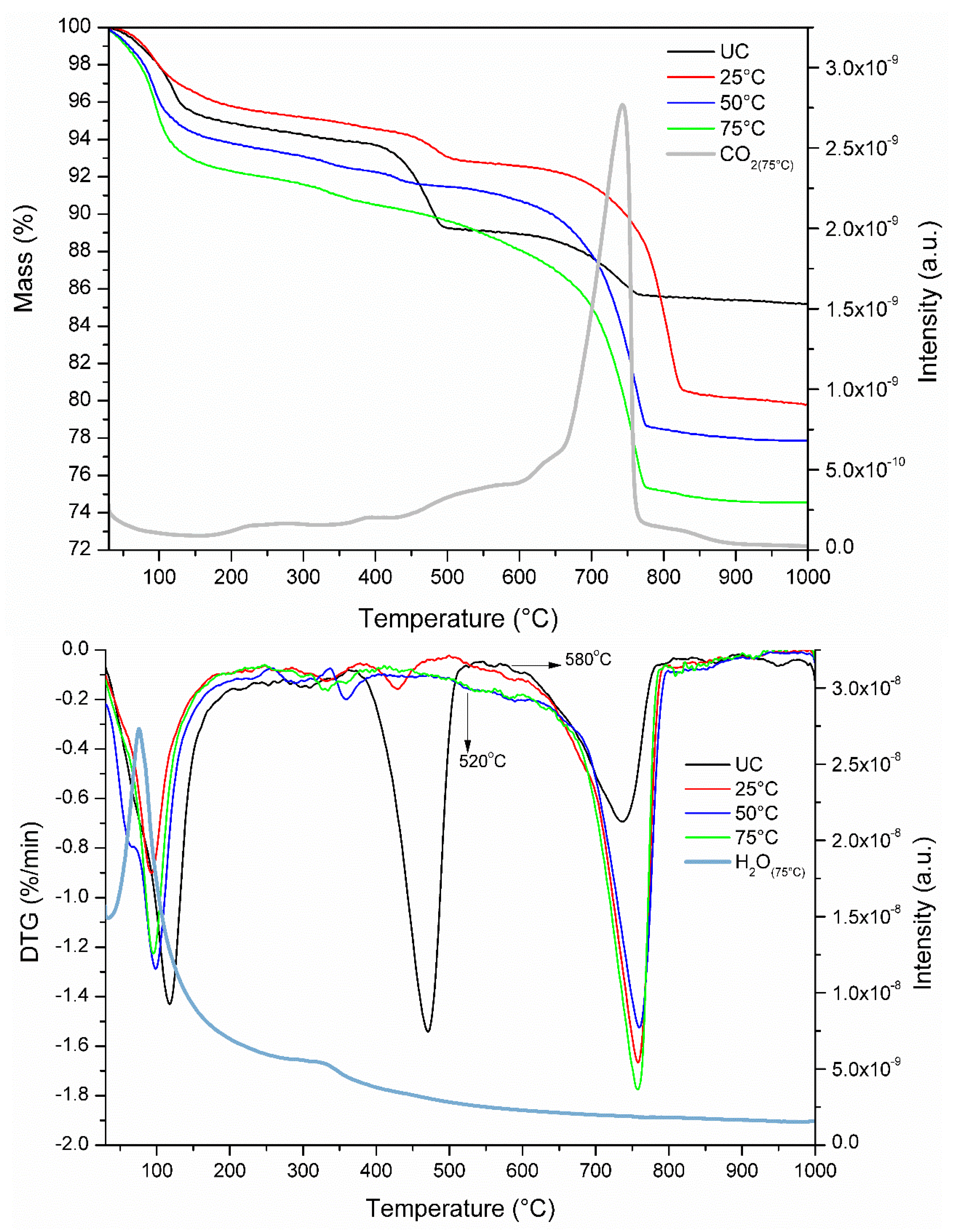
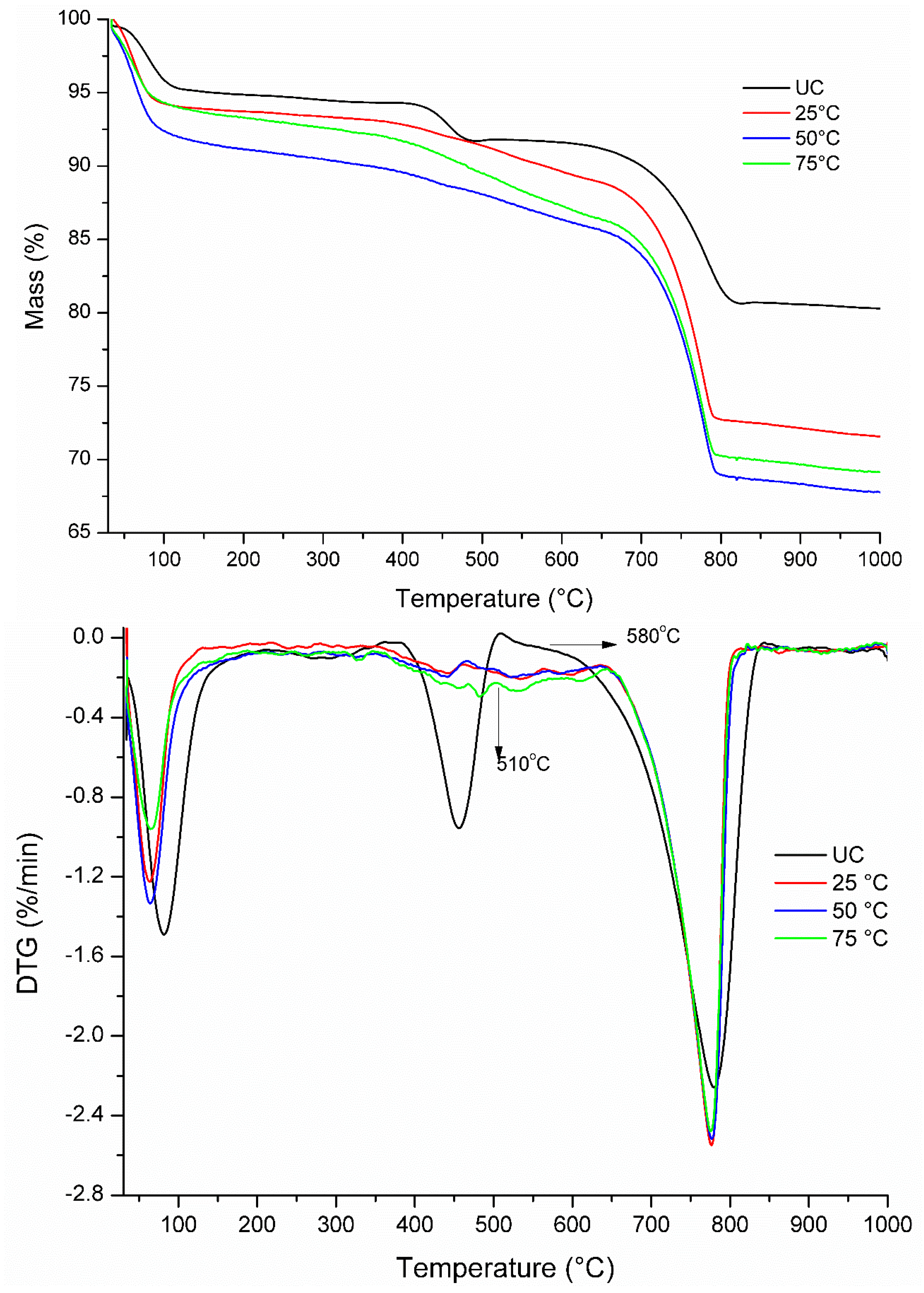
3.2. Thermal Analysis
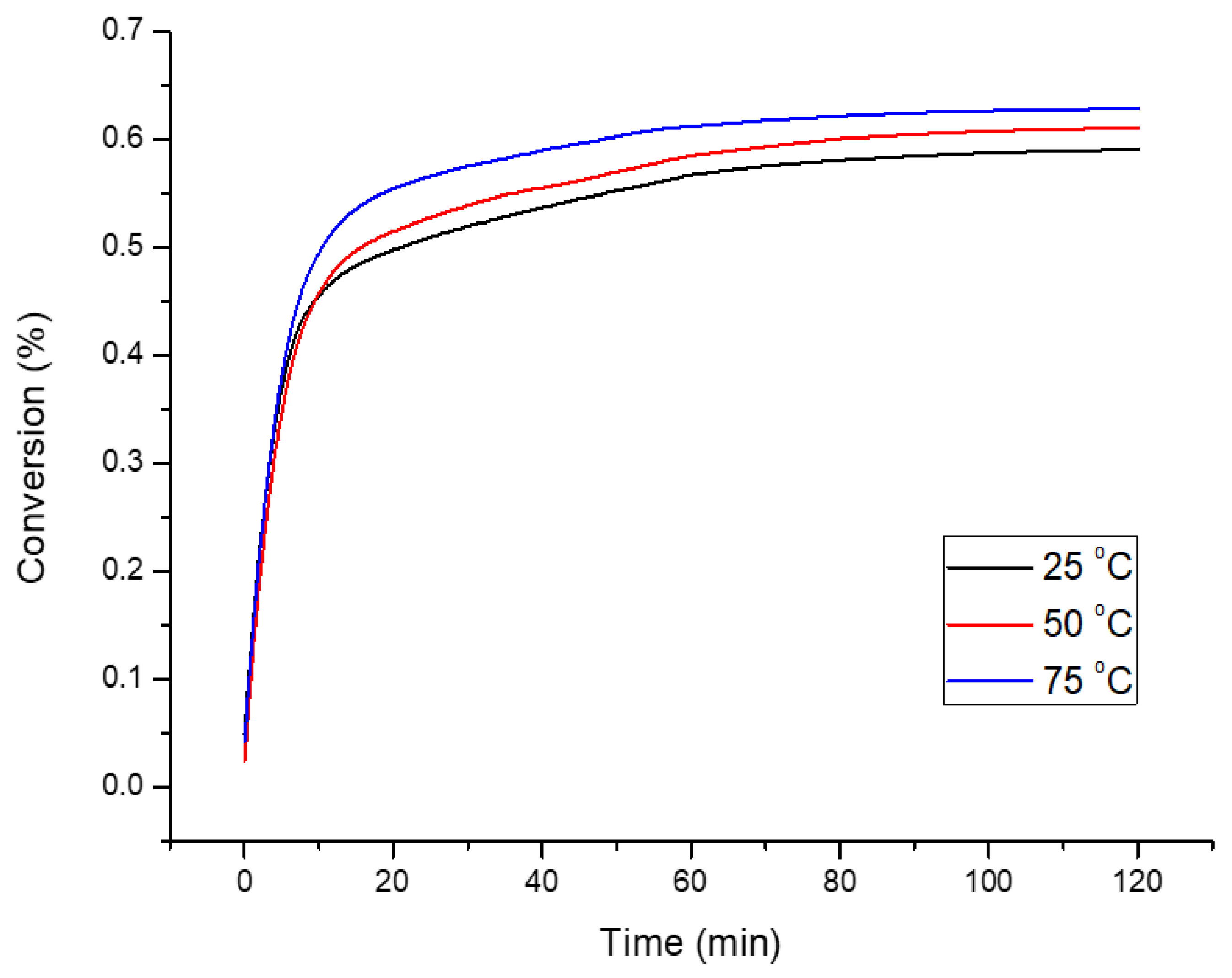
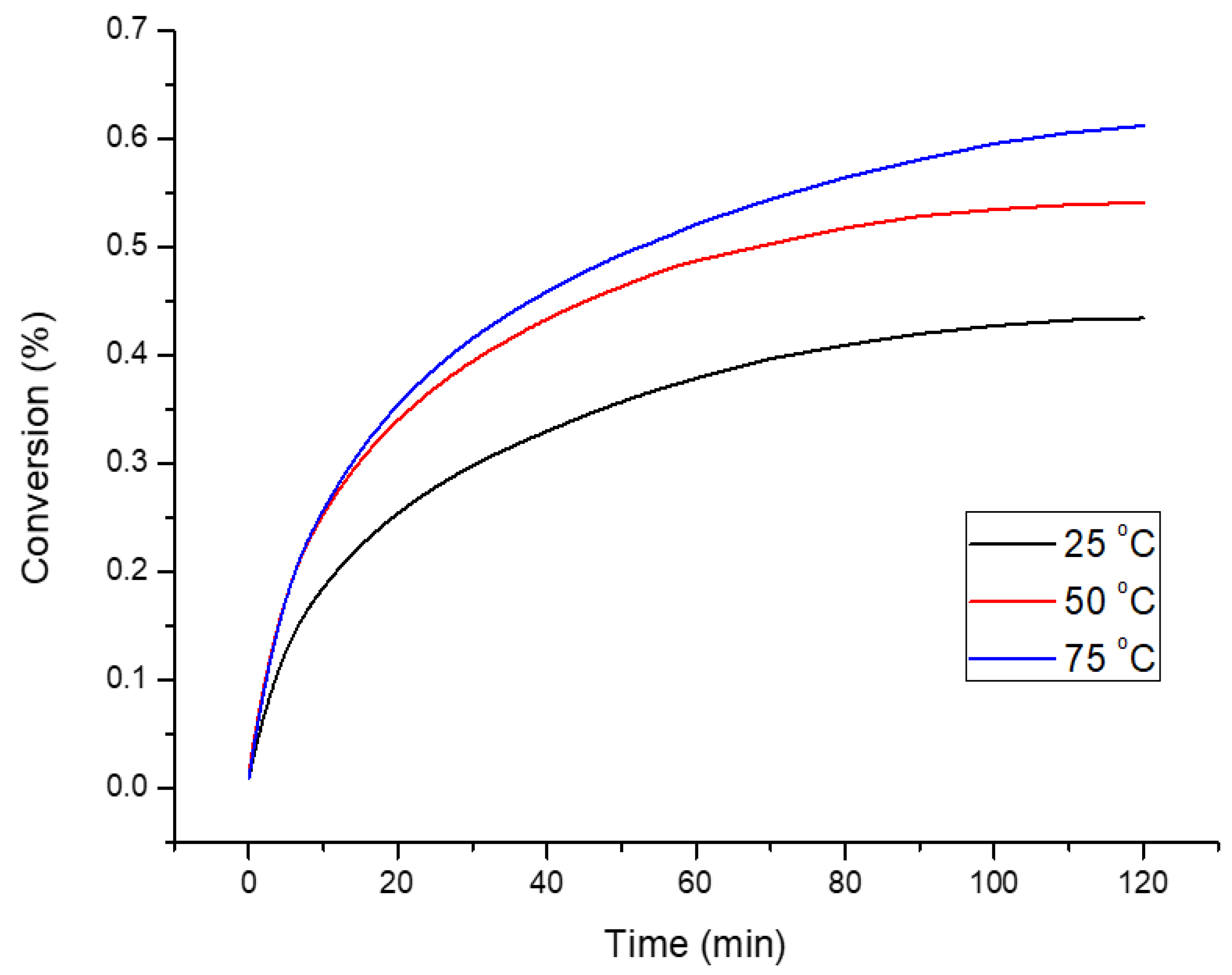
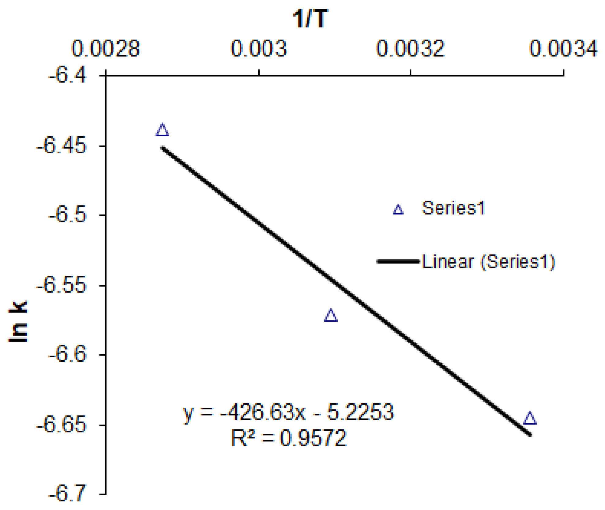
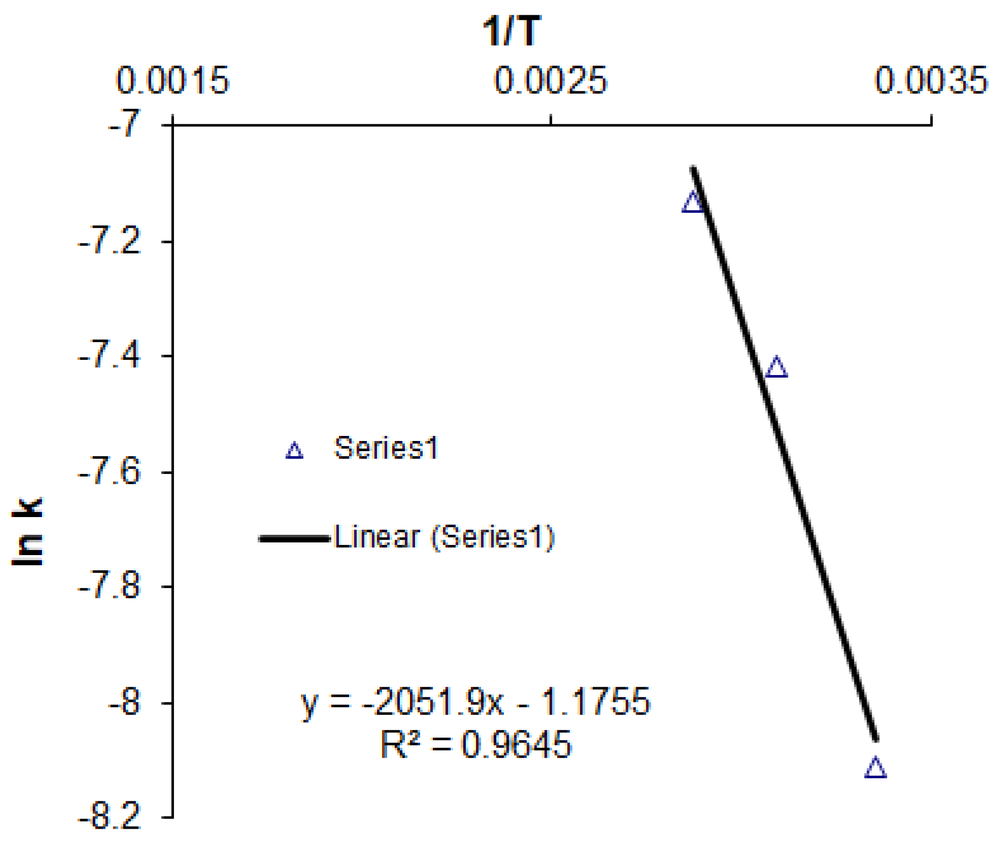
3.3. Kinetic Analysis
3.4. Microstructural and Mineralogical Changes
3.4.1. XRD Analysis
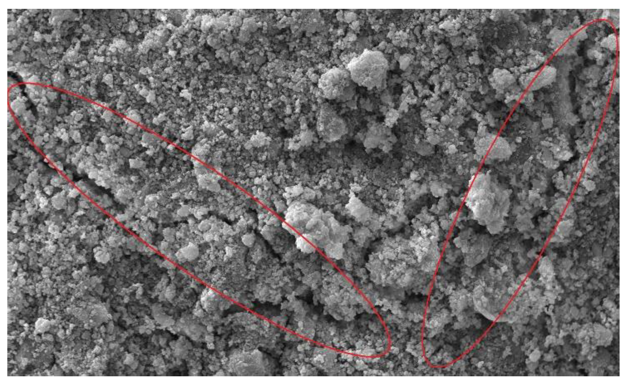
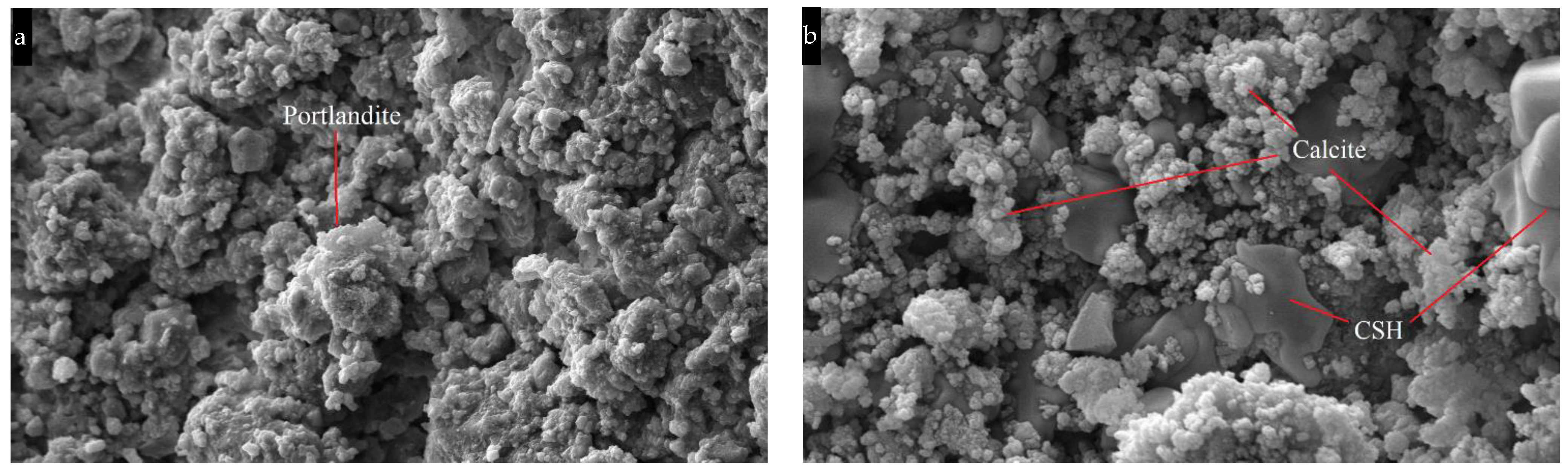
3.4.2. SEM Analysis
3.5. Current Results in the Context of Sustainable Building Materials
4. Conclusions
- Increase in gas pressure and CO2 concentration exhibited positive correlation with the CO2 uptake and compressive strength values;
- Compaction pressure as a pre-processing parameter is mainly related to compressive strength. However, due to its physical effect on diffusivity, the compaction pressure increase showed an increase in strength while limiting CO2 penetration in a small amount, causing less CO2 uptake;
- Despite higher carbonation degrees at elevated curing temperatures, the compressive strength did not increase accordingly. High temperatures can increase the risks of micro cracks and change the micro-mechanical property of CSH, which in turn weakens the compressive strength;
- Additionally, at high temperatures, due to the reduction of liquid water in compacts, uneven and fast formation of particulates (amorphous formations of calcite polymorphs) on the surfaces of mainly Ca(OH)2 can appear, yet such determination is rather complex for short curing times (2 h);
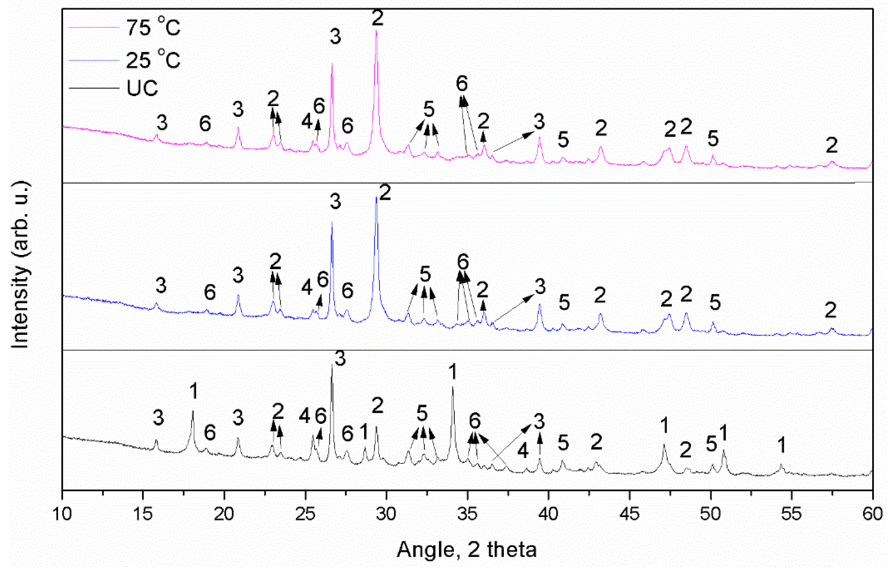
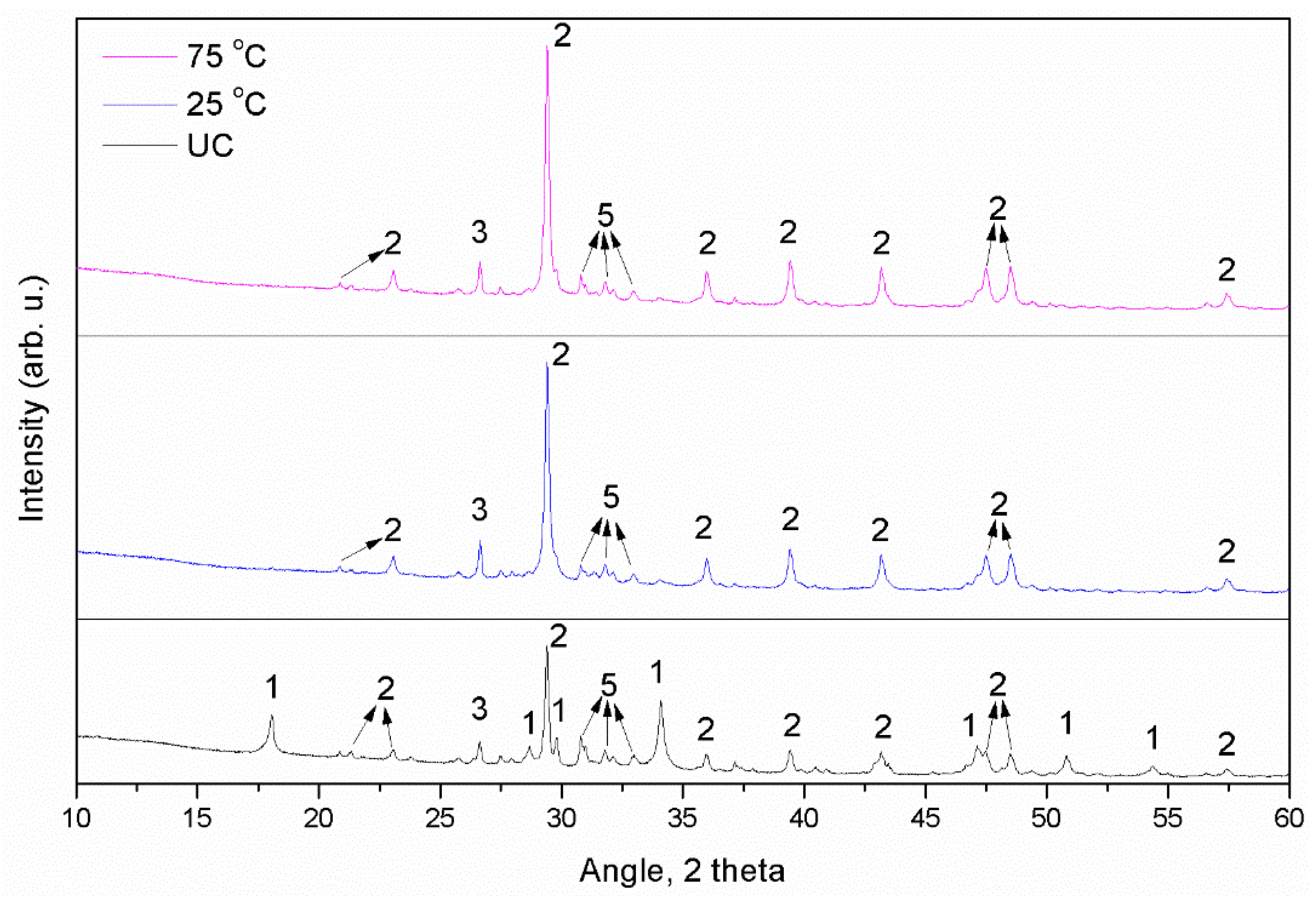
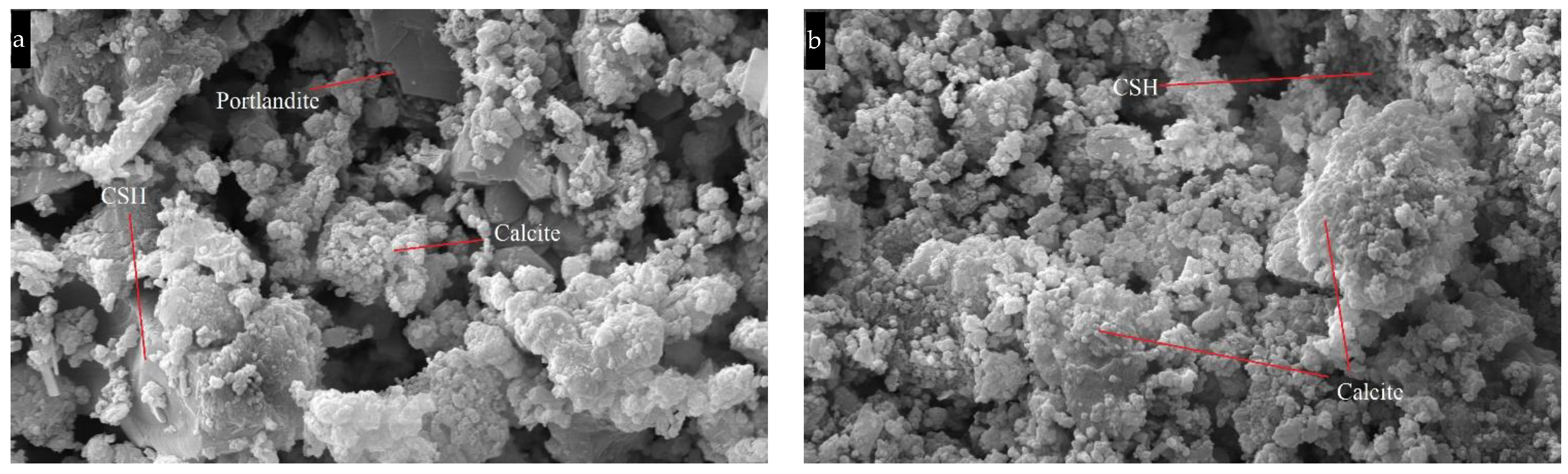
- SEM and XRD analysis further proved that Calcite was the dominant phase after carbonation and portlandite was almost completely consumed;
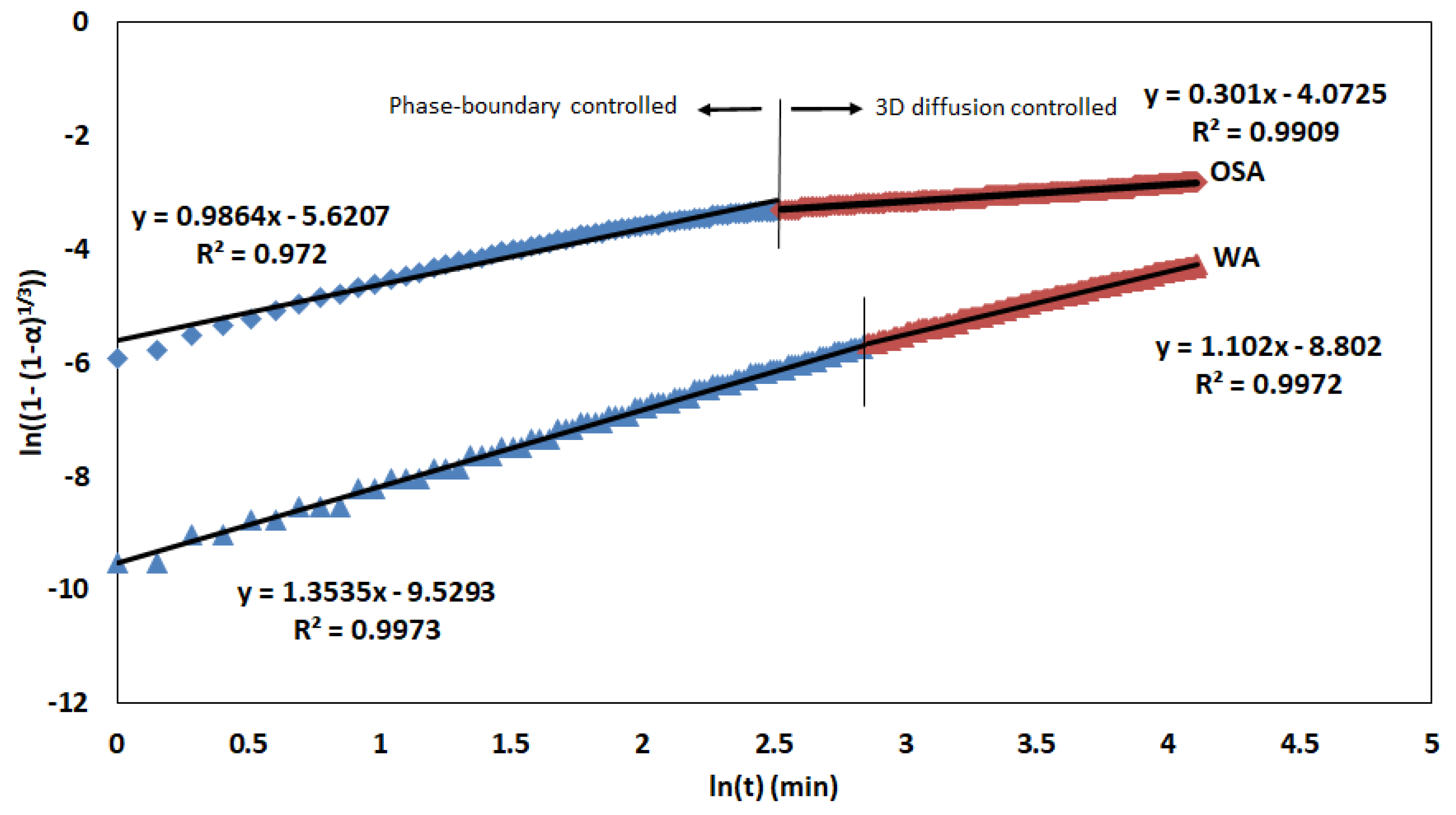
- Reaction mechanism corresponds to 3D-diffusion-controlled reaction order model for both OSA and WA. CO2 diffusion through the product layer was estimated to be the rate-controlling step and surface passivation was clearer for OSA, except for WA, due to the short curing time. Calculated apparent activation energies are given for OSA as 3.55 kJ/mol and for WA as 17.06 kJ/mol.
Author Contributions
Funding
Institutional Review Board Statement
Informed Consent Statement
Data Availability Statement
Acknowledgments
Conflicts of Interest
Appendix A

| OSA | WA | |||||
|---|---|---|---|---|---|---|
| UC | 25 °C | 75 °C | UC | 25 °C | 75 °C | |
| pH | 12.5 | 11.5 | 11.4 | 12.7 | 12.1 | 11.4 |
Appendix B

| T, K | 1/T | k | ln k |
|---|---|---|---|
| 298 | 0.003355705 | 1.3 × 10⁻³ | −6.64539 |
| 323 | 0.003095975 | 1.4 × 10⁻³ | −6.57128 |
| 348 | 0.002873563 | 1.60 × 10⁻³ | −6.43775 |
| Slope: | −426.63 | Intercept: | −5.2253 |
| EA | 3.54700182 | kJ/mol | |
| A | 0.005378746 | min−1 |

| T, K | 1/T | k | ln k |
|---|---|---|---|
| 298 | 0.003355705 | 3.0 × 10⁻⁴ | −8.11173 |
| 323 | 0.003095975 | 6.0 × 10⁻⁴ | −7.41858 |
| 348 | 0.002873563 | 8.00 × 10⁻⁴ | −7.1309 |
| Slope: | −2051.9 | Intercept: | −1.1755 |
| EA | 17.0594966 | kJ/mol | |
| A | 0.308664609 | min−1 |
References
- Torgal, F.P.; Shi, C.; Angel, S.P. Accelerated carbon dioxide sequestration. In Carbon Dioxide Sequestration in Cementitious Construction Materials; Woodhead Publishing: Sawston, UK, 2018; pp. 81–101. [Google Scholar]
- IEA Cement Tracking Report, November 2021. Available online: https://www.iea.org/reports/cement (accessed on 4 December 2021).
- Scrivener, K.L.; John, V.M.; Gartner, E.M. Eco-efficient cements: Potential economically viable solutions for a low-CO2 cement-based Materials Industry. Cem. Concr. Res. 2018, 114, 2–26. [Google Scholar] [CrossRef]
- HeidelbergCement AG. HeidelbergCement to Install the World’s First Full-Scale CCS Facility in a Cement Plant. Available online: https://www.heidelbergcement.com/en/pr-15-12-2020 (accessed on 15 December 2020).
- Yi, H.; Xu, G.; Cheng, H.; Wang, J.; Wan, Y.; Chen, H. An overview of utilization of steel slag. Procedia Environ. Sci. 2012, 16, 791–801. [Google Scholar] [CrossRef] [Green Version]
- Von Greve-Dierfeld, S.; Lothenbach, B.; Vollpracht, A.; Wu, B.; Huet, B.; Andrade, C.; Medina, C.; Thiel, C.; Gruyaert, E.; Vanoutrive, H.; et al. Understanding the carbonation of concrete with supplementary cementitious materials: A critical review by RILEM TC 281-CCC. Mater. Struct. 2020, 53, 136. [Google Scholar] [CrossRef]
- Hemalatha, T.; Ramaswamy, A. A review on fly ash characteristics—Towards promoting high volume utilization in developing sustainable concrete. J. Clean. Prod. 2017, 147, 546–559. [Google Scholar] [CrossRef]
- Ramezanianpour, A.A. Cement Replacement Materials; Springer Geochemistry/Mineralogy: New York, NY, USA, 2014; pp. 70–74. ISBN 9783642367205. [Google Scholar]
- Moon, E.J.; Choi, Y.C. Carbon dioxide fixation via accelerated carbonation of cement-based materials: Potential for construction materials applications. Constr. Build. Mater. 2019, 199, 676–687. [Google Scholar] [CrossRef]
- Mo, L.; Zhang, F.; Deng, M.; Jin, F.; Al-Tabbaa, A.; Wang, A. Accelerated carbonation and performance of concrete made with steel slag as binding materials and aggregates. Cem. Concr. Compos. 2017, 83, 138–145. [Google Scholar] [CrossRef]
- Guo, M.Z.; Tu, Z.; Poon, C.S.; Shi, C. Improvement of properties of architectural mortars prepared with 100% recycled glass by CO2 curing. Constr. Build. Mater. 2018, 179, 138–150. [Google Scholar] [CrossRef]
- Wei, Z.; Wang, B.; Falzone, G.; La Plante, E.C.; Okoronkwo, M.U.; She, Z.; Oey, T.; Balonis, M.; Neithalath, N.; Pilon, L.; et al. Clinkering-free cementation by fly ash carbonation. J. CO2 Util. 2018, 23, 117–127. [Google Scholar] [CrossRef]
- Woodall, C.M.; McQueen, N.; Pilorgé, H.; Wilcox, J. Utilization of mineral carbonation products: Current state and potential. Greenh. Gas. Sci. Technol. 2019, 9, 1096–1113. [Google Scholar] [CrossRef]
- Chang, R.; Kim, S.; Lee, S.; Choi, S.; Kim, M.; Park, Y. Calcium carbonate precipitation for CO2 storage and utilization: A review of the carbonate crystallization and polymorphism. Front. Energy Res. 2017, 5, 17. [Google Scholar] [CrossRef] [Green Version]
- Uibu, M.; Kuusik, R.; Andreas, L.; Kirsimäe, K. The CO2 binding by Ca-Mg-silicates in direct aqueous carbonation of oil shale ash and steel slag. Energy Procedia 2011, 4, 925–932. [Google Scholar] [CrossRef] [Green Version]
- Bobicki, E.R.; Liu, Q.; Xu, Z.; Zeng, H. Carbon capture and storage using alkaline industrial wastes. Prog. Energy Combust. Sci. 2012, 38, 302–320. [Google Scholar] [CrossRef]
- Gunning, P.J.; Hills, C.D.; Carey, P.J. Accelerated carbonation treatment of industrial wastes. Waste Manag. 2010, 30, 1081–1090. [Google Scholar] [CrossRef]
- Leben, K.; Motlep, R.; Konist, A.; Pihu, T.; Kirsimäe, K. Carbon dioxide sequestration in power plant Ca-rich ash waste deposits. Oil Shale 2021, 38, 65–88. [Google Scholar] [CrossRef]
- Leben, K.; Mõtlep, R.; Paaver, P.; Konist, A.; Pihu, T.; Paiste, P.; Kirsimäe, K. Long-term mineral transformation of Ca-rich oil shale ash waste. Sci. Total Environ. 2019, 658, 1404–1415. [Google Scholar] [CrossRef] [Green Version]
- Usta, M.C.; Yörük, C.R.; Hain, T.; Paaver, P.; Snellings, R.; Rozov, E.; Uibu, M. Evaluation of New Applications of Oil Shale Ashes in Building Materials. Minerals 2020, 10, 765. [Google Scholar] [CrossRef]
- Gunning, P.J.; Hills, C.D.; Carey, P.J. Production of lightweight aggregate from industrial waste and carbon dioxide. Waste Manag. 2009, 29, 2722–2728. [Google Scholar] [CrossRef]
- Quaghebeur, M.; Nielsen, P.; Horckmans, L.; Van Mechelen, D. Accelerated Carbonation of Steel Slag Compacts: Development of High-Strength Construction Materials. Front. Energy Res. 2015, 3, 52. [Google Scholar] [CrossRef]
- Nielsen, P.; Boone, M.A.; Horckmans, L.; Snellings, R.; Quaghebeur, M. Accelerated Carbonation of Steel Slag Monoliths at Low CO2 Pressure–Microstructure and Strength Development. J. CO2 Util. 2020, 36, 124–134. [Google Scholar] [CrossRef]
- Sanjuán, M.Á.; Estévez, E.; Argiz, C. Carbon dioxide absorption by blast-furnace slag mortars in function of the curing intensity. Energies 2019, 12, 2346. [Google Scholar] [CrossRef] [Green Version]
- Ohenoja, K.; Rissanen, J.; Kinnunen, P.; Illikainen, M. Direct carbonation of peat-wood fly ash for carbon capture and utilization in construction application. J. CO2 Util. 2020, 40, 101203. [Google Scholar] [CrossRef]
- Liu, W.; Teng, L.; Rohani, S.; Qin, Z.; Zhao, B.; Xu, C.C.; Liang, B. CO2 mineral carbonation using industrial solid wastes: A review of recent developments. Chem. Eng. J. 2021, 416, 129093. [Google Scholar] [CrossRef]
- Affordable. Versatile. Sustainable. Available online: https://www.enefit.com/technology/power-production (accessed on 14 February 2022).
- Okia. Utilitas Tallinn. Utilitas. Available online: https://www.utilitas.ee/en/company/as-utilitas-tallinn/ (accessed on 14 February 2022).
- Electricity and Heat Production. Available online: https://www.energia.ee/en/ettevottest/tehnoloogia/elektri-ja-sooja-tootmine?tabgroup_1=auvere (accessed on 14 February 2022).
- Arandigoyen, M.; Bicer-Simsir, B.; Alvarez, J.I.; Lange, D.A. Variation of microstructure with carbonation in lime and blended pastes. Appl. Surf. Sci. 2006, 252, 7562–7571. [Google Scholar] [CrossRef] [Green Version]
- Barnes, P.; Bensted, J. Structure and Performance of Cements, 2nd ed.; CRC Press: Boca Raton, FL, USA, 2001. [Google Scholar] [CrossRef]
- Horkoss, S.; Escadeillas, G.; Rizk, T.; Lteif, R. The effect of the source of cement SO3 on the expansion of mortars. Case Stud. Constr. Mater. 2016, 4, 62–72. [Google Scholar] [CrossRef] [Green Version]
- ASTM International. Standard Specification for Coal Fly Ash and Raw or Calcined Natural Pozzolan for Use in Concrete (ASTM C618-19). Available online: https://www.astm.org/ (accessed on 14 February 2022).
- Humidity Fixed Points of Binary Saturated Aqueous Solutions: Semantic Scholar. Available online: https://www.semanticscholar.org/paper/Humidity-Fixed-Points-of-Binary-Saturated-Aqueous-Gree-span/9a90c8e8fb71c152ae3bacf9904e6c761cdf9de7 (accessed on 14 February 2022).
- Fernandezbertos, M.; Simons, S.; Hills, C.; Carey, P. A review of accelerated carbonation technology in the treatment of cement-based materials and sequestration of CO2. J. Hazard. Mater. 2004, 112, 193–205. [Google Scholar] [CrossRef]
- Pizzol, V.D.; Mendes, L.M.; Savastano, H., Jr.; Frías, M.; Davila, F.J.; Cincotto, M.A.; Tonoli, G.H.D. Mineralogical and microstructural changes promoted by accelerated carbonation and ageing cycles of hybrid fiber–cement composites. Constr. Build. Mater. 2014, 68, 750–756. [Google Scholar] [CrossRef]
- Cui, H.; Tang, W.; Liu, W.; Dong, Z.; Xing, F. Experimental study on effects of CO2 concentrations on concrete carbonation and diffusion mechanisms. Constr. Build. Mater. 2015, 93, 522–527. [Google Scholar] [CrossRef]
- Mohamed, M.F.; Nor, A.M.; Suhor, M.F.; Singer, M.; Choi, Y.S.; Nešic, S. Water Chemistry for Corrosion Prediction in High Pressure CO2 Environments. Corrosion 2011, NACE-11375. [Google Scholar]
- Fang, Y.; Chang, J. Microstructure changes of waste hydrated cement paste induced by accelerated carbonation. Constr. Build. Mater. 2015, 76, 360–365. [Google Scholar] [CrossRef]
- Liu, X.; Feng, P.; Cai, Y.; Yu, X.; Yu, C.; Ran, Q. Carbonation behavior of calcium silicate hydrate (CSH): Its potential for CO2 capture. Chem. Eng. J. 2022, 431, 134243. [Google Scholar] [CrossRef]
- Nejad, F.M.; Tolouei, M.; Nazari, H.; Naderan, A. Effects of calcium carbonate nanoparticles and fly ash on mechanical and permeability properties of concrete. Advances in Civil Engineering. Materials 2018, 7, 651–668. [Google Scholar] [CrossRef]
- Usmany, Y.; Putranto, W.A.; Bayuseno, A.P.; Muryanto, S. Crystallization of calcium carbonate (CaCO3) in a flowing system: Influence of Cu2+ additives on induction time and crystalline phase transformation. AIP Conf. Proc. 2016, 1725, 20093. [Google Scholar] [CrossRef] [Green Version]
- Shih, Y. Thermal degradation and kinetic analysis of biodegradable PBS/multiwalled carbon nanotube nanocomposites. J. Polym. Sci. Part B Polym. Phys. 2009, 47, 1231–1239. [Google Scholar] [CrossRef]
- Nam, S.-Y.; Seo, J.; Thriveni, T.; Ahn, J.-W. Accelerated carbonation of municipal solid waste incineration bottom ash for CO2 sequestration. Geosystem Eng. 2012, 15, 305–311. [Google Scholar] [CrossRef]
- Um, N.; Nam, S.-Y.; Ahn, J.-W. Effect of accelerated carbonation on the leaching behavior of Cr in municipal solid waste incinerator bottom ash and the carbonation kinetics. Mater. Trans. 2013, 54, 1510–1516. [Google Scholar] [CrossRef] [Green Version]
- Khawam, A.; Flanagan, D.R. Solid-state kinetic models: Basics and mathematical fundamentals. J. Phys. Chem. B. 2006, 110, 17315–17328. [Google Scholar] [CrossRef] [PubMed]
- Nikulshina, V.; Gálvez, M.; Steinfeld, A. Kinetic analysis of the carbonation reactions for the capture of CO2 from air via the Ca(OH)2–CaCO3–CaO solar thermochemical cycle. Chem. Eng. J. 2007, 129, 75–83. [Google Scholar] [CrossRef]
- Monkman, S.; Shao, Y. Assessing the carbonation behavior of cementitious materials. J. Mater. Civ. Eng. 2006, 18, 768–776. [Google Scholar] [CrossRef]
- European Commission. Outcome of Proceedings. Circular Economy in the Construction Sector. Available online: https://data.consilium.europa.eu/doc/document/ST-14653-2019-INIT/en/pdf (accessed on 14 March 2022).
- European Commission. European Green Deal: Commission Proposes to Boost Renovation and Decarbonisation of Buildings. Available online: https://ec.europa.eu/commission/presscorner/detail/en/IP_21_6683 (accessed on 14 March 2022).
- European Commission. Construction Products Regulation Acquis. Internal Market, Industry, Entrepreneurship and SMEs. Available online: https://ec.europa.eu/growth/sectors/construction/construction-products-regulation-cpr/acquis_en (accessed on 14 March 2022).
- Carbon8 Systems. Available online: http://www.c8s.co.uk/ (accessed on 12 April 2022).
- Carbon-Negative Concrete. CarbiCrete. Available online: http://www.carbicrete.com/ (accessed on 12 April 2022).
- Carbstone. VITO. Available online: https://vito.be/en/carbstone (accessed on 12 April 2022).
- Telesca, A.; Marroccoli, M.; Montagnaro, F.; Tomasulo, M.; Valenti, G.L. Enhancement of selectivity toward ettringite during hydrothermal processes on fluidized bed combustion wastes for the manufacture of preformed building components. RSC Adv. 2015, 5, 101887–101893. [Google Scholar] [CrossRef]
- Telesca, A.; Calabrese, D.; Marroccoli, M.; Valenti, G.L.; Montagnaro, F. Study of the hydrothermal treatments of residues from fluidized bed combustors for the manufacture of ettringite-based building elements. Fuel Process. Technol. 2014, 126, 188–191. [Google Scholar] [CrossRef]
- Li, X.; Chen, Q.; Huang, K.; Ma, B.; Wu, B. Cementitious properties and hydration mechanism of circulating fluidized bed combustion (CFBC) desulfurization ashes. Constr. Build. Mater. 2012, 36, 182–187. [Google Scholar] [CrossRef]
- Ohenoja, K.; Tanskanen, P.; Wigren, V.; Kinnunen, P.; Körkkö, M.; Peltosaari, O.; Österbacka, J.; Illikainen, M. Self-hardening of fly ashes from a bubbling fluidized bed combustion of peat, forest industry residuals, and wastes. Fuel 2016, 165, 440–446. [Google Scholar] [CrossRef]


| Component | OSA1 | WA | LFA |
|---|---|---|---|
| SiO2 | 29.38 | 18.08 | 17.38 |
| Al2O3 | 9.58 | 2.73 | 4.13 |
| TiO2 | 0.578 | 0.19 | 0.21 |
| Fe2O3 | 5.12 | 1.17 | 2.43 |
| MnO | 0.067 | 0.32 | 0.03 |
| CaO | 34.67 | 44.44 | 42.21 |
| MgO | 3.12 | 2.82 | 3.75 |
| Na2O | 0.12 | 0.52 | 0.10 |
| K2O | 3.91 | 7.69 | 0.81 |
| P2O5 | 0.128 | 4.14 | 0.13 |
| SO3 | 4.96 | 4.35 | 4.97 |
| L.O.I. | 7.73 | 12.79 | 22.90 |
| Component | OSA (%) | WA (%) | LFA (%) |
|---|---|---|---|
| Quartz | 15 | 7.5 | 5 |
| K-feldspar | 14.2 | 3.2 | 3 |
| Plagioclase | 0.7 | 0 | 0 |
| Mica | 3.6 | 0 | 0 |
| Calcite | 9.8 | 27.7 | 3 |
| Lime | 17 | 20.3 | 0 |
| Portlandite | 1.4 | 3 | 18 |
| Periclase | 4.2 | 2.9 | 2 |
| Anhydrite | 9.3 | 0 | 0 |
| C2S | 13.9 | 4.1 | 3 |
| Merwinite | 3.2 | 4.3 | 2 |
| Akermanite | 4.5 | 3.8 | 5 |
| Sylvite | 0 | 1.7 | 0 |
| Arcanite | 0 | 8.6 | 0 |
| Hematite | 2.3 | 0 | 0 |
| Apatite | 0 | 12.6 | 0 |
| CSH (tobermerite) | 0 | 0 | 45 |
| Gypsum | 0 | 0 | 2 |
| Ettringite | 0 | 0 | 2 |
| Test Parameters | Curing CO2% | Curing Gas Pressure | Curing Temperature | Compaction Pressure | Curing RH | Curing Time | |
|---|---|---|---|---|---|---|---|
| Compaction pressure | 150 kgf/cm2 | 100% CO2 | 10 bar | 25 °C | - | 61–68% | 2 h |
| 300 kgf/cm2 | - | ||||||
| Gas Pressure | 5 bar | 100% CO2 | - | 25 °C | 150 kgf/cm2 | ||
| 10 bar | |||||||
| 15 bar | |||||||
| CO2% | 100% CO2 | - | 10 bar | 25 °C | 150 kgf/cm2 | ||
| 16% CO2 | |||||||
| Temperature | 25 °C | 100% CO2 | 10 bar | - | 150 kgf/cm2 | ||
| 50 °C | |||||||
| 75 °C | |||||||
| OSA | WA | LFA | M1 | M2 | |
|---|---|---|---|---|---|
| 150 kg/cm2 | 1595 | 1830 | 1340 | 1380 | 1420 |
| 300 kg/cm2 | 1720 | 1970 | 1470 | 1560 | 1690 |
Publisher’s Note: MDPI stays neutral with regard to jurisdictional claims in published maps and institutional affiliations. |
© 2022 by the authors. Licensee MDPI, Basel, Switzerland. This article is an open access article distributed under the terms and conditions of the Creative Commons Attribution (CC BY) license (https://creativecommons.org/licenses/by/4.0/).
Share and Cite
Usta, M.C.; Yörük, C.R.; Uibu, M.; Hain, T.; Gregor, A.; Trikkel, A. CO2 Curing of Ca-Rich Fly Ashes to Produce Cement-Free Building Materials. Minerals 2022, 12, 513. https://doi.org/10.3390/min12050513
Usta MC, Yörük CR, Uibu M, Hain T, Gregor A, Trikkel A. CO2 Curing of Ca-Rich Fly Ashes to Produce Cement-Free Building Materials. Minerals. 2022; 12(5):513. https://doi.org/10.3390/min12050513
Chicago/Turabian StyleUsta, Mustafa Cem, Can Rüstü Yörük, Mai Uibu, Tiina Hain, Andre Gregor, and Andres Trikkel. 2022. "CO2 Curing of Ca-Rich Fly Ashes to Produce Cement-Free Building Materials" Minerals 12, no. 5: 513. https://doi.org/10.3390/min12050513