Article

Study on Fracture and Seepage Evolution Law of Stope Covered by Thin Bedrock under Mining Influence

1
School of Mines, China University of Mining and Technology, Xuzhou 221116, China
2
State Key Laboratory of Coal Resources and Safe Mining, China University of Mining and Technology, Xuzhou 221116, China
3
State Key Laboratory for Geomechanics and Deep Underground Engineering, China University of Mining and Technology, Xuzhou 221116, China
*
Author to whom correspondence should be addressed.
Minerals 2022, 12(3), 375; https://doi.org/10.3390/min12030375
Submission received: 12 January 2022 / Revised: 12 March 2022 / Accepted: 16 March 2022 / Published: 18 March 2022
(This article belongs to the Special Issue Green Mining of Coal Mine in China)

Abstract

:
Aiming to better understand the fracture evolution characteristics of thin bedrock affected by mining, a program was developed to establish a numerical calculation model for the fracture evolution of the overlying rock in the stope under the coupled seepage-stress condition. The fracturing law of mining overburden during the advancing process of the coal seam working face has been deeply studied. The dynamic change process of the development height of the overburden fissure zone is analyzed. The results show that with the advance of the working surface, shear and tension compound rupture occurs in the overlying rock layer bottom-up. The rupture penetrates into the sand-water layer and forms a stable rupture zone, which terminates at the bottom of the clay layer in the vertical direction and no longer develops upward. The equivalent stress concentration area is obviously separated at the bottom of the clay layer. Additionally, there is no obvious damage to the clay layer, indicating that the integrity of the clay layer has been protected. This pattern is consistent with the field monitoring results. Under the dual action of mining stress and pore water pressure, the bedrock aquifer ruptured in a wide range, and gradually caused water to flow to the goaf. The low pore pressure zone runs through the entire bedrock layer and ends at the bottom of the clay layer; also, the effective velocity of pore fluid shows a consistent pattern. The on-site water inflow monitoring results found that the main source of water inflow was the sandstone aquifer in the bedrock section, and the shallow groundwater and surface water did not enter the working face in large quantities with coal mining. This shows that the clay layer has a good water barrier effect, effectively blocking the inflow of shallow groundwater or surface water into the working face. It also shows that the “soft–hard” roof layer combination feature greatly buffers the impact of mining on the water isolation layer and has a good water separation effect.

1. Introduction

There are many coal-forming periods in China with very complex endowment conditions, among which many coal fields have extensive areas of thin bedrock coal seams with abundant coal reserves [1]. The following impact characteristics are prevalent: shallow burial of the main recoverable coal seam; thicker loose strata covering the surface [2]; thin bedrock layer above the coal seam; long mining history and multiple water damage impacts [3]. Mining overburden damage during coal seam mining usually connects the working face with the loose strata [4], and even ripples to the surface to form longitudinal through fissures [5].
In essence, the destruction of the surrounding rock caused by coal mining is a spatiotemporal evolutionary process [6], in which the surrounding rock in the mining area will gradually form a fracture zone [7]. During the advance of the stope, the fracture zone develops gradually [8], usually penetrating the bedrock and entering the Cenozoic loose overburden [9]. This causes the hydraulic connection between the coal seam roof sandstone fissure aquifer [10], the Cenozoic loose overburden pore water-bearing sand layer and the surface shallow aquifer and the working face, resulting in water inrush hazards [11]. Especially in some Cenozoic loose overburden pore water-bearing sand layers and shallow aquifers with strong water richness and large water storage [12], the threat of shallow groundwater and surface water damage is more prominent when thin bedrock coal seams are mined [13]. If the shallow groundwater and surface water with large storage capacity and strong water-richness enter the well in large quantities due to the influence of coal seam mining [14], they will not only pose a threat to the safe production at the working face, affecting the local residents’ industrial, agricultural and domestic water [15], but they will also cause serious damage to the ecological environment of groundwater resources in the region [16]. In order to realize the protection of groundwater resources [17], it is necessary to conduct in-depth research on the evolution law of the roof overlying fracture zone in the goaf under mining conditions [18].
Considering the water resources and ecological fragility [19], coal mining activities should be carried out at the premise of protecting the local hydrological environment and ecology [20], without taking water resources destruction as the cost [21]. To this end, Fan [22] proposed the research idea of “water conserving mining” to show the direction for alleviating the water resources damage caused by coal mining. Subsequently, a large number of scholars have conducted fruitful studies and discussions on various aspects, such as the height of the overburden hydraulic fracture zone [23], the thickness of the effective protection layer and the stability of the water barrier mining [24]. Among them, the highly accurate identification of the water-conducting fissure zone is a prerequisite for realizing safe underwater coal mining and water preserving mining [25]. Xu et al. [26] proposed the evaluation method of “effective water barrier thickness”. Fan et al. [27] suggested that the water barrier capacity of mining overburden is determined by both structural and hydrological water barrier properties. These studies play an important guiding role in the protection of water resources in engineering [28].
However, due to the special geological structural characteristics of thin bedrock, the water barrier damage induced by the mining process is the root cause of the damage to groundwater resources and ecological environment [29]. Therefore, it is important to study the fracture law of overlying rock movement during the advancing process of the working face to reveal the fracture evolution mechanism under the combined action of seepage and stress field [30]. In view of this, combined with the specific engineering geological conditions of the third mining area of Sanyuan Coal Mine, this manuscript establishes a numerical calculation model for the fracture evolution of the overlying rock in the gob under the coupled seepage-stress condition. The dynamic change process of the development height of the fissure zone of the mining overburden is analyzed, the evolution mechanism of the permeability characteristics of the mining overburden is revealed, and the water blocking effect of the overlying rock under the mining influence is reasonably evaluated.

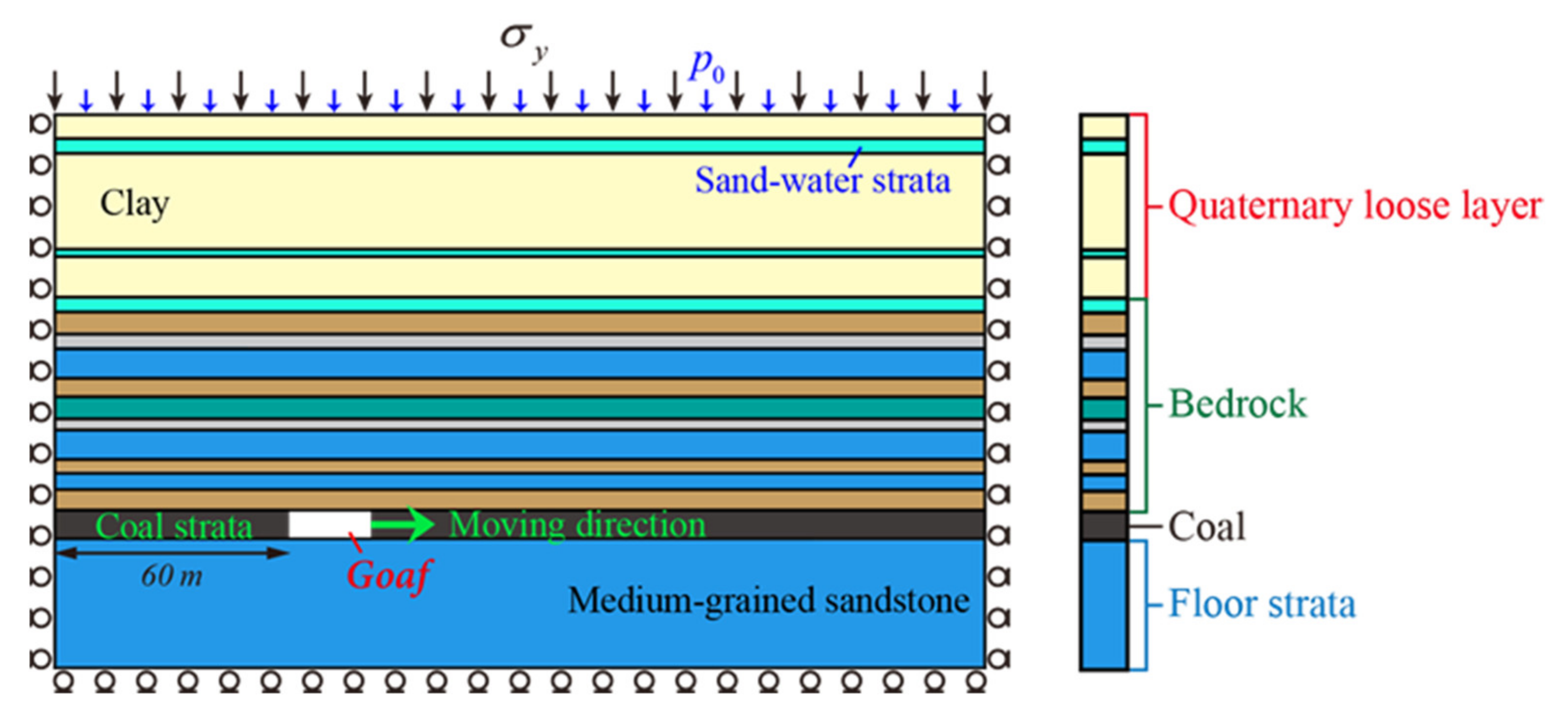
2. Background of the Engineering

Sanyuan Coalfield is located in the pre-mountainous area in the west of the middle section in Taihang Mountains, at the southern edge of Changzhi Basin, and the landform type is low mountain hilly area. The 3301 first mining face, located in the eastern area of the three mining areas, contains coal seams with a thickness greater than 6.7 m, a bedrock with thickness less than 50 m and a Quaternary overburden of about 200 m in most areas. The overlying rock seam of coal seam No. 3 in the third mining area, from the direct top to the top boundary of weathered bedrock, is largely composed of soft–hard–soft–hard–soft lithology. In this soft–hard structure, it is easy for the hard rock layer to form a stable bearing structure; at the same time, the soft rock layer is effective in inhibiting the development of mining fissures.
According to the feedback from the hydrogeological borehole, the sandstone aquifer at the roof of No. 3 coal seam, consisting mainly of medium- and fine-grained sandstone, is a direct water-filled aquifer of No. 3 coal seam with weak water-richness. The bedrock has multiple aquifers with medium water richness, which is the main source of water supply for the coal seam mining face. The Quaternary loose layers are fully covered, with a layer thickness of 166.7–206.0 m, and the formation occurrence is generally less than 8. Its aquifer is mainly composed of yellow, brownish-yellow powder-coarse sand, gravel layer, etc., which constitutes a lens body of different sizes. The water content and permeability are determined by the degree of development in the thickness of sand and gravel layers, which are generally moderately rich in water. The medium-grained sand layer near the surface is a submerged aquifer with high water-richness and large water storage capacity. In the low-lying areas of the region, shallow groundwater is naturally exposed and forms surface ponds (Figure 1).

3. Numerical Modeling and Scheme

A plane strain numerical calculation model (Figure 2) was created in the finite element software ABAQUS along the working face with a model size of 250 m × 150 m. According to the results of the hydrogeological survey, the model is generalized from the top to the bottom into the Quaternary loose layer, bedrock, coal seam, and floor rock layer, whose heights are 50 m, 58 m, 7 m and 35 m, respectively. The rock layer subdivision thickness and basic mechanical parameters are shown in Table 1. In this study, the basic mechanical parameters of the element (including Young’s modulus, internal cohesion, internal frictional angle, and so on) were obtained by trial and error method. Through a large number of numerical experiments, when the deviation between the numerical results and the experimental results is reduced to a reasonable range, the most reasonable parameters are selected.
The boundary conditions of the model are set as: the left and right boundaries and the bottom surface are set as displacement constraints. The height of the overlying rock layer of the model is 200 m, and it is loaded on the upper boundary of the model in the form of a uniform load. After calculation of in situ stress, a stress load of 5 MPa is applied. For seepage boundaries, the left, right, and bottom boundaries of the model are set as impermeable boundaries, respectively. A pore water pressure of 1.0 MPa is applied at the top to simulate the reinforcement effect of the far field on the confined aquifer on the roof. The flow of water in each rock layer obeys Darcy’s law. The simulated coal seam is cut from a distance of 60 m from the left boundary of the model, and the coal seam is mined from left to right. The calculation is carried out by means of step-by-step excavation. The excavation step is calculated according to the normal advancing speed of the working face in the actual location. The calculation is carried out by means of step-by-step excavation. The excavation step is calculated according to the normal advancing speed of the working face in the actual project of 3.3 m/d. The excavation distance of each step is L = 10 m, and the duration step is 3d.
The initial state of each rock formation is assumed to contain randomly and uniformly distributed original fractures [31], and the numerical model of rock damage rupture evolution with random distribution is established by using the secondary development subroutine USDFLD of ABAQUS platform [32]. It is assumed that the percentage of damaged units in a rock formation is n 0 , and its basic mechanical parameters are about 1/2 of those of intact units. To describe the rock fracture evolution law, fracture initiation and extension criteria are introduced in this study. When the unit stress satisfies the maximum tensile stress criterion or the Mohr-Coulomb criterion, the unit will initiate fracture [33]. It should be noted that since the tensile strength of the rock is much less than the compressive strength, tensile damage is judged in priority, shear damage is judged only if no tensile damage occurs [34,35,36]. The stiffness degradation is carried out for the damaged unit, and the stiffness is 1/10 of the original initial stiffness, while the permeability coefficient is increased by a factor of 100. Figure 3 shows the specific numerical calculation flow.

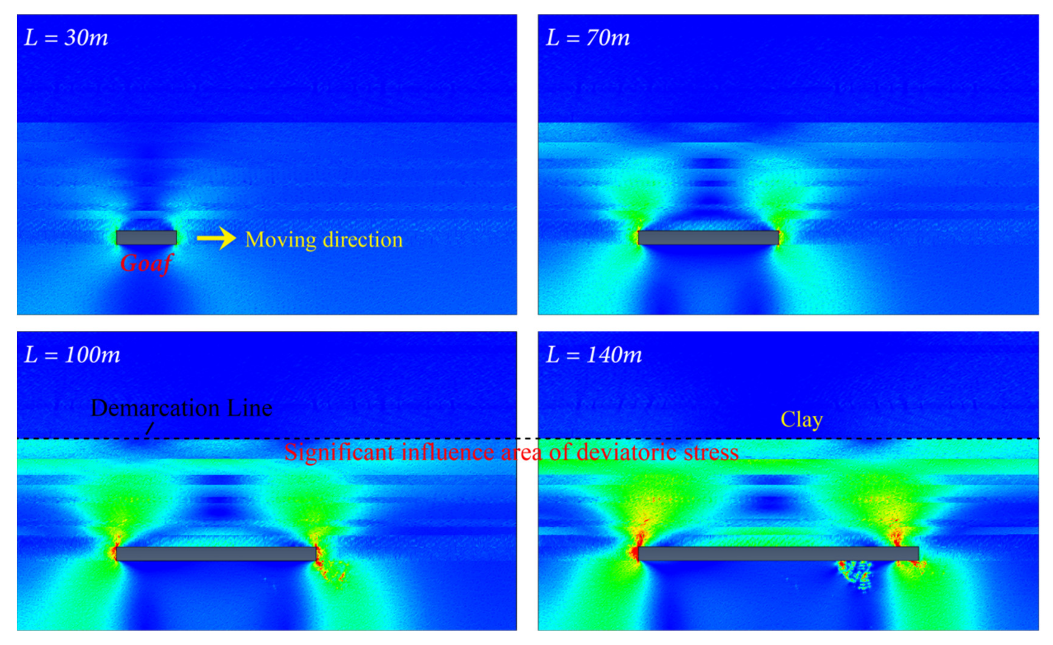
4. Fracture Evolution Law of Overlying Rock during Mining

After the coal seam is mined, the stress around the goaf is redistributed to form the mining stress, which causes the deformation and damage of the rock mass around the goaf. Figure 4 shows the distribution law of tension and shear rupture zone during the working face advance. When the excavation distance L = 30 m, there is a wide range of tensional damage zone in the roof and floor surrounding rocks of the mining area, while the shear rupture zone is mainly concentrated in the cuttings and near the working section. Figure 5 shows the height variation law of the fracture zone of the roof overburden during the working face advance. When the excavation distance L is in the range of 0~40 m, the height of the roof overlying fracture zone increases slowly. The medium-grained sandstone in point B (Figure 5) is an 8 m-thick hard rock layer, which plays the main bearing role and plays a certain obstructive role for the breakage of the rock layer. However, the top stratum is composed of soft and hard strata. Once the hard stratum breaks (L = 50 m), the upper soft strata will also be destroyed rapidly. For example, when L = 60 m, the upper three weak rock layers break rapidly until another hard rock layer D. When L = 70 m (Figure 4), a wide range of tensile rupture zones appear in several rock layers, at which time the hard rock layer D is locally broken in tension and begins to evolve gradually. When L = 100 m, shear and tension compound rupture occurs in multiple areas of the upper weak rock layer in the hard rock layer D. The rupture penetrates to the sand-water layer E and forms a stable rupture zone. With the advancement of the working face, the failure of the rock layer ends at the bottom of the clay layer F in the vertical direction, and no longer develops upward. According to the analysis of the reasons, the loose clay layer has the characteristics of strong plasticity and will not be cut off as a whole due to the severe damage of the rock stratum below. It itself has a certain buffer effect, so the height of the final mining fracture zone will not develop upward.
In order to investigate the development pattern of the mining fracture zone, observation drilling was carried out on the surface after the mining of the 3301 working face was completed. The development height of the mining fracture zone was determined comprehensively by measuring the leakage of drilling flushing fluid, the change in the drilling water level, the destruction of the drilling core and various anomalies during the drilling process. Figure 6 demonstrates the consumption of drilling flushing fluid and the hydrological changes in the hole opening during the drilling process of the observed mining fracture zone. The thickness of the coal seam is 7 m, and the vertical depth of the coal roof from the hole is 245.9 m. Since the drilling depth of 193.10 m, the first leakage occurred in the hole, while the consumption of drilling flushing fluid increased and changed significantly, especially in the coarse-grained sandstone and medium-grained sandstone layers, where the cores were broken and longitudinal fractures appeared (Figure 6). This indicates that the drilling has obvious water leakage, that is, the leakage of flushing fluid increases significantly, indicating that the rock formation in this area is severely ruptured and cannot block the water flow, so it represents the mining fissure zone. After drilling to 229.7 m, the number of drilling rigs dropped, and the core recovery rate decreased to 33.6% to 48.5%. The core was broken, the oblique fissures were developed, and the fault dip angle was disordered. This shows that the damage of the rock formation is extremely serious, and its thickness is 16.2 m. Combined with Figure 6, the height of the mining fracture zone can be obtained as 36.6 + 16.2 = 52.8 m. The development height is the sand layer at the bottom of the Quaternary, and it does not enter the clay layer. This is basically consistent with the numerical simulation result (54.5 m).
In order to analyze the fracture characteristics of the roof surrounding rock more intuitively, the equivalent stress σ e = σ 1 σ 3 is defined in this study. The equivalent stress can control the failure of the rock mass, and has important directional significance for judging the fracture trend of the unit, which is more likely when more damage to the surrounding rock has occurred. Figure 7 shows the trend of surrounding rock failure during the advancement of the face using equivalent stress quantification. Near the open cut and the working section, a high-equivalent stress concentration area similar to a “double petal” appeared, indicating that the stope is prone to rupture during the advance of the stope. With the continuous increase in the excavation distance L, the scope of the high-equivalent stress zone continues to expand. Due to the “soft–hard” distribution characteristics of the roof strata, the equivalent stress concentration zone is clearly separated at the bottom of the clay layer. Under the two conditions of L = 100 and 140 m, it can be seen that the stope advance did not have a significant impact on the clay layer, indicating that the integrity of the clay layer and the waterproof effect were not greatly affected by the damage. It is comprehensively indicated that the “soft–hard” roof stratum feature greatly weakens the degree of roof rupture caused by mining. Among them, the hard rock layer has the main bearing function, and the soft rock layer such as the loose sand layer greatly buffers the impact of mining damage, and the two have natural bearing and water resistance capabilities.

5. Evolution Law of Seepage Field

During the advancement of the working face, the redistribution of the roof overlying stress field not only changed the distribution of the fissure field in the surrounding rock of the stope, but also changed the permeability of the rock mass and the flow state of groundwater. Once the stope is pushed into the near-surface aquifer, it will cause water loss on the surface land, damage to vegetation, and even the danger of water inrush from the working face. Figure 8 shows the penetration law of the roof overlying rock during the advancing process of the working face. The mining causes the movement and destruction of the overlying rock, while a large low pore pressure zone appears above the roof. With the increasing excavation distance L, this area gradually expands and the height in vertical direction gradually increases. This indicates that the mining fissures in the roof of the coal seam gradually sprout, expand and penetrate, causing the water in the surrounding high-osmotic pressure aquifer to penetrate into it. When L = 100 m, the overburden low pore pressure zone penetrates the whole bedrock layer and stops at the bottom of the clay layer, which can also be illustrated by the pore fluid effective velocity change law. However, the Quaternary clay layer exhibits an obvious water-resistance effect, so that the water in the sand-water layer sandwiched between the two clay layers does not flow vertically, but flows independently and horizontally (L = 100 m). This indicates that the clay layer has a good water barrier effect, effectively blocking the inflow of shallow groundwater or surface water into the working face. At the same time, it also shows that the “soft–hard alternate” roof slate layer combination feature greatly buffer the impact of mining on the water isolation layer, and has a good water separation effect.
During the mining process of the 3301 working face, the change in water surge was monitored on site, as shown in Figure 9. During the mining period of the 3301 working face, the water inflow was relatively small (less than 6.0 m3/h). With the increase in the advancing distance of the 3301 working face, the water inflow did not increase significantly, relatively smooth changes. This shows that during the mining of the 3301 working face, the main source of water inflow was the sandstone aquifer water in the bedrock section, and the shallow groundwater and surface water did not enter the working face in large quantities with the mining of the coal seam. This also supports the seepage law of the roof overlying rock in Figure 8. This shows that the overall integrity of the clay layer is not damaged by mining, and its water insulation remains good.

6. Conclusions

(1)
Based on seepage and mechanics theory, a rock seepage-stress coupling equation with random damage elements is established. The numerical calculation model for the fracture evolution of the overlying rock in the stope under the coupled seepage-stress condition was established by using the ABAQUS secondary development program. A multi-scale numerical calculation method for the whole process analysis of rock mass destruction under seepage-stress coupling is realized.
(2)
The whole process of the overlying rock fracture evolution during the advancing process of the working face is reproduced. The results show that with the advancement of the working face, shear and tension compound rupture occurs in the overlying rock layer bottom-up. It gradually penetrates into the sand-water layer and forms a stable rupture zone, which ends at the bottom of the clay layer in the vertical direction and no longer develops upward. The damage height reached 54.5 m, which was consistent with the field monitoring results, indicating the accuracy of the numerical calculation results. The equivalent stress is used to quantify the failure trend of the surrounding rock during the advancing process of the working face. The equivalent stress concentration area is obviously separated at the bottom of the clay layer, while there is no obvious damage to the clay layer. This shows that the characteristics of the “soft–hard” roof layer greatly weaken the rupture degree of the roof caused by mining, protecting the integrity of the clay layer and ensuring its good water insulation.
(3)
The permeation law of the overlying rock of the roof during the advancement of the working face was analyzed, and the results were that: under the dual action of mining stress and pore water pressure, the bedrock aquifer ruptured in a wide range, and gradually caused water to flow to the goaf. The low pore pressure zone runs through the entire bedrock layer and ends at the bottom of the clay layer; also, the effective velocity of pore fluid shows a consistent pattern. This indicates that the clay layer has a good water barrier effect, effectively blocking the flow of shallow groundwater or surface water into the working face. This also shows that the “soft–hard” roof layer combination feature greatly buffers the impact of mining on the water isolation layer and has good water separation effect.
(4)
The monitoring results of on-site water inflow showed that during the mining of the working face, the main source of water inflow was the sandstone water layer of the bedrock section, and the shallow groundwater and surface water did not enter the working face in large quantities with the mining of the coal seam. The clay in the Quaternary overburden has not been damaged as a whole due to coal mining, which shows that the roof rock layer combination characteristics of “soft–hard alternate” greatly buffer the destructive effect of mining on the clay water separation layer, and that this has a good water separation effect.

Author Contributions

Data curation, K.D. and C.J.; formal analysis, Z.L.; funding acquisition, Z.L.; investigation, B.R. and S.W.; methodology, B.R.; resources, L.W.; software, Z.L. and Z.P.; validation, C.J.; visualization, K.D.; writing—original draft, Z.L.; writing—review & editing, S.W. and Z.P. All authors have read and agreed to the published version of the manuscript.

Funding

This research was funded by the Fundamental Research Funds for the Central Universities (Grant No. 2020QN42).

Institutional Review Board Statement

Not applicable.

Informed Consent Statement

Not applicable.

Data Availability Statement

The data used to support the findings of this study are included within the article.

Acknowledgments

The authors would like to acknowledge the editor for their valuable comments on the improvement of this paper.

Conflicts of Interest

The authors declare that there are no conflict of interest regarding the publication of this article.

References

  1. Wu, G.M.; Bai, H.B.; Wu, L.Y.; He, S.X. Study on the Influence of Bedrock Thickness on Deformation and Failure of Overlying Soil Layer in Thin Bedrock Coal Seam Mining. J. Min. Sci. 2020, 56, 518–528. [Google Scholar] [CrossRef]
  2. Lian, X.G.; Zhang, Y.J.; Yuan, H.Y.; Wang, C.L.; Guo, J.T.; Liu, J.B. Law of Movement of Discontinuous Deformation of Strata and Ground with a Thick Loess Layer and Thin Bedrock in Long Wall Mining. Appl. Sci. 2020, 10, 2874. [Google Scholar] [CrossRef] [Green Version]
  3. Yang, W.; Xia, X. Study on mining failure law of the weak and weathered composite roof in a thin bedrock working face. J. Geophys. Eng. 2018, 15, 2370–2377. [Google Scholar] [CrossRef] [Green Version]
  4. Kratzsch, H. Mining Subsidence Engineering; Springer Science & Business Media: Berlin, Germany, 2012. [Google Scholar]
  5. Guo, Y.; Wei, J.; Gui, H.; Zhang, Z.; Hu, M. Evaluation of changes in groundwater quality caused by a water inrush event in Taoyuan coal mine, China. Environ. Earth Sci. 2020, 79, 1–15. [Google Scholar] [CrossRef]
  6. Mandal, R.; Maity, T.; Chaulya, S.K.; Prasad, G.M. Laboratory investigation on underground coal gasification technique with real-time analysis. Fuel 2020, 275, 117865. [Google Scholar] [CrossRef]
  7. Zhang, S.; Tang, S.; Zhang, D.; Fan, G.; Wang, Z. Determination of the Height of the Water-Conducting Fractured Zone in Difficult Geological Structures: A Case Study in Zhao Gu No. 1 Coal Seam. Sustainability 2017, 9, 1077. [Google Scholar] [CrossRef] [Green Version]
  8. Reddish, D.; Whittaker, B. Subsidence: Occurrence, Prediction and Control; Elsevier: Amsterdam, The Netherlands, 2012. [Google Scholar]
  9. Yang, W.; Xia, X. Prediction of mining subsidence under thin bedrocks and thick unconsolidated layers based on field measurement and artificial neural networks. Comput. Geosci. 2013, 52, 199–203. [Google Scholar] [CrossRef]
  10. Brady, B.H.; Brown, E.T. Rock Mechanics: For Underground Mining; Springer Science & Business Media: Berlin, Germany, 2006. [Google Scholar]
  11. Liu, S.; Li, W.; Wang, Q.; Pei, Y. Investigation on mining-induced fractured zone height developed in different layers above Jurassic coal seam in western China. Arab. J. Geosci. 2018, 11, 30. [Google Scholar] [CrossRef]
  12. Zhao, K.; Xu, N.; Mei, G.; Tian, H. Predicting the distribution of ground fissures and water-conducted fissures induced by coal mining: A case study. SpringerPlus 2016, 5, 977. [Google Scholar] [CrossRef] [Green Version]
  13. Fu, B.; Wang, B. An Influence Study of Face Length Effect on Floor Stability under Water-Rock Coupling Action. Geofluids 2021, 2021, 1–13. [Google Scholar] [CrossRef]
  14. Ma, D.; Wang, J.; Li, Z. Effect of particle erosion on mining-induced water inrush hazard of karst collapse pillar. Environ. Sci. Pollut. Res. 2019, 26, 19719–19728. [Google Scholar] [CrossRef] [PubMed]
  15. Zhang, J.; Guo, L.; Mu, W.; Liu, S.; Zhao, D. Water-inrush Risk through Fault Zones with Multiple Karst Aquifers Underlying the Coal Floor: A Case Study in the Liuzhuang Coal Mine, Southern China. Mine Water Environ. 2021, 40, 1037–1047. [Google Scholar] [CrossRef]
  16. Lin, Z.; Zhang, B.; Guo, J. Analysis of a Water-Inrush Disaster Caused by Coal Seam Subsidence Karst Collapse Column under the Action of Multi-Field Coupling in Taoyuan Coal Mine. Comput. Model. Eng. Sci. 2021, 126, 311–330. [Google Scholar]
  17. Xu, Y.; Zhang, E.; Luo, Y.; Zhao, L.; Yi, K. Mechanism of Water Inrush and Controlling Techniques for Fault-Traversing Roadways with Floor Heave Above Highly Confined Aquifers. Mine Water Environ. 2020, 39, 320–330. [Google Scholar] [CrossRef]
  18. Ma, J.; Yin, D.; Jiang, N.; Wang, S.; Yao, D. Application of a superposition model to evaluate surface asymmetric settlement in a mining area with thick bedrock and thin loose layer. J. Clean. Prod. 2021, 314, 128075. [Google Scholar] [CrossRef]
  19. Tang, C.; Yao, Q.; Li, Z.; Zhang, Y.; Ju, M. Experimental study of shear failure and crack propagation in water-bearing coal samples. Energy Sci. Eng. 2019, 7, 2193–2204. [Google Scholar] [CrossRef]
  20. Li, Z.; Yu, S.; Zhu, W.; Feng, G.; Xu, J. Dynamic loading induced by the instability of voussoir beam structure during mining below the slope. Int. J. Rock Mech. Min. 2020, 132, 104343. [Google Scholar] [CrossRef]
  21. Yao, Q.L.; Tang, C.J.; Xia, Z.; Liu, X.L.; Zhu, L.; Chong, Z.H.; Hui, X.D. Mechanisms of failure in coal samples from underground water reservoir. Eng. Geol. 2020, 267, 105494. [Google Scholar] [CrossRef]
  22. Fan, L. Some scientific issues in water-preserved coal mining. J. China Coal Soc. 2019, 44, 667–674. [Google Scholar]
  23. Miao, X.; Cui, X.; Wang, J.a.; Xu, J. The height of fractured water-conducting zone in undermined rock strata. Eng. Geol. 2011, 120, 32–39. [Google Scholar] [CrossRef]
  24. Fan, L.; Ma, X. A review on investigation of water-preserved coal mining in western China. Int. J. Coal Sci. Technol. 2018, 5, 411–416. [Google Scholar] [CrossRef] [Green Version]
  25. Xu, S.; Zhang, Y.; Shi, H.; Zhang, Z.; Chen, J. Impacts of Aquitard Properties on an Overlying Unconsolidated Aquifer in a Mining Area of the Loess Plateau: Case Study of the Changcun Colliery, Shanxi. Mine Water Environ. 2020, 39, 121–134. [Google Scholar] [CrossRef]
  26. Xu, Y.; Luo, Y.; Li, J.; Li, K.; Cao, X. Water and Sand Inrush during Mining Under Thick Unconsolidated Layers and Thin Bedrock in the Zhaogu No. 1 Coal Mine, China. Mine Water Environ. 2018, 37, 336–345. [Google Scholar] [CrossRef]
  27. Fan, G.; Zhang, D. Mechanisms of Aquifer Protection in Underground Coal Mining. Mine Water Environ. 2015, 34, 95–104. [Google Scholar] [CrossRef]
  28. Song, H.; Xu, J.; Fang, J.; Cao, Z.; Li, T. Potential for mine water disposal in coal seam goaf: Investigation of storage coefficients in the Shendong mining area. J. Clean. Prod. 2019, 244, 118646. [Google Scholar] [CrossRef]
  29. Fei, Y.; Liu, S.; Xu, Y.; Zhao, L. Failure Analysis of Thin Bedrock and Clay Roof in Underground Coal Mining: Case Study in Longdong Coal Mine. Int. J. Geomech. 2020, 20, 04020187. [Google Scholar] [CrossRef]
  30. Zhang, H.; Tu, M.; Cheng, H.; Tang, Y. Breaking mechanism and control technology of sandstone straight roof in thin bedrock stope. Int. J. Rock Mech. Min. 2020, 30, 259–263. [Google Scholar] [CrossRef]
  31. Li, T.; Li, L.; Tang, C.; Zhang, Z.; Li, M. A coupled hydraulic-mechanical-damage geotechnical model for simulation of fracture propagation in geological media during hydraulic fracturing. J. Pet. Sci. Eng. 2019, 173, 1390–1416. [Google Scholar] [CrossRef]
  32. Wang, S.; Li, Z.; Yuan, R.; Li, G.; Li, D. A shear hardening model for cohesive element method and its application in modeling shear hydraulic fractures in fractured reservoirs. J. Nat. Gas. Sci. Eng. 2020, 83, 103580. [Google Scholar] [CrossRef]
  33. Tidke, A.R.; Adhikary, S. Seismic fragility analysis of the Koyna gravity dam with layered rock foundation considering tensile crack failure. Eng. Fail. Anal. 2021, 125, 105361. [Google Scholar] [CrossRef]
  34. Zhang, X.X.; Wang, J.G.; Gao, F.; Wang, X.L. Numerical Study of Fracture Network Evolution during Nitrogen Fracturing Processes in Shale Reservoirs. Energies 2018, 11, 2503. [Google Scholar] [CrossRef] [Green Version]
  35. Li, W.; Jiang, B.; Gu, S.; Yang, X.; Shaikh, F.U.A. Experimental study on the shear behaviour of grout-infilled specimens and micromechanical properties of grout-rock interface. J. Cent. South. Univ. 2022, 1–14. [Google Scholar]
  36. Feng, Q.; Jin, J.; Zhang, S.; Liu, W.; Yang, X.; Li, W. Study on a Damage Model and Uniaxial Compression Simulation Method of Frozen–Thawed Rock. Rock Mech. Rock Eng. 2022, 55, 187–211. [Google Scholar] [CrossRef]
Figure 1. 3301 working face in Sanyuan coal mine and water accumulated area.
Minerals 12 00375 g001
Figure 2. Numerical calculation model.
Minerals 12 00375 g002
Figure 3. Flow chart of numerical simulation solution.
Minerals 12 00375 g003
Figure 4. Distribution of tension and shear fracture zones in the process of overburden fracture and collapse: (a) tension failure distribution; (b) shear failure distribution.
Minerals 12 00375 g004
Figure 5. Height of failure zone of roof overburden fracture zone and corresponding triggered rock stratum.
Minerals 12 00375 g005
Figure 6. The variation in water level, consumption of drilling flushing fluid and core fracture characteristics with depth.
Minerals 12 00375 g006
Figure 7. The variation pattern of the equivalent stress field with the advance of the working face.
Minerals 12 00375 g007
Figure 8. (a) Variation law of pore pressure; (b) Variation law of the pore fluid effective velocity.
Minerals 12 00375 g008
Figure 9. Variation law of water inflow with mining distance.
Minerals 12 00375 g009
Table 1. Numerical model parameters.
Quaternary Loose LayerStrataThickness
(m)
Young’s Modulus
(GPa)
Internal Cohesion
(MPa)
Internal
Frictional
Angle (°)
The Proportion of Damaged Elements (%)Tensile Strength
(MPa)
Permeability
(m2)
Clay7.00.80.5530.0100.161 × 10–15
Sand-water layer4.00.10.2020.080.105 × 10–8
Clay26.00.80.5530.0100.161 × 10–15
Sand-water layer2.00.10.2020.080.105 × 10–8
Clay11.00.80.5530.0100.161 × 10–15
BedrockSand-water layer4.00.10.2020.080.105 × 10–8
Mudstone6.012.12.3020.990.401 × 10–13
Sandy mudstone4.016.33.4529.090.451 × 10–12
Medium-grained sandstone8.035.05.2030.576.501 × 10–10
Mudstone5.016.33.4529.090.451 × 10–13
Fine-grained sandstone6.038.05.9124.451.981 × 10–10
Sandy mudstone3.016.33.4529.070.451 × 10–12
Medium-grained sandstone8.035.05.2030.576.501 × 10–10
Mudstone4.012.12.3020.990.401 × 10–13
Medium-grained sandstone4.035.05.2030.576.501 × 10–10
Mudstone6.012.12.3020.990.401 × 10–13
Coal3# Coal7.05.01.6030.0100.205 × 10–12
Floor strataMedium-grained sandstone35.035.05.2030.556.501 × 10–10
Publisher’s Note: MDPI stays neutral with regard to jurisdictional claims in published maps and institutional affiliations.

