
Experimental Study on the Characteristics and Formation Mechanism of Dynamic Filter Cake for Slurry Shield Tunneling


Abstract
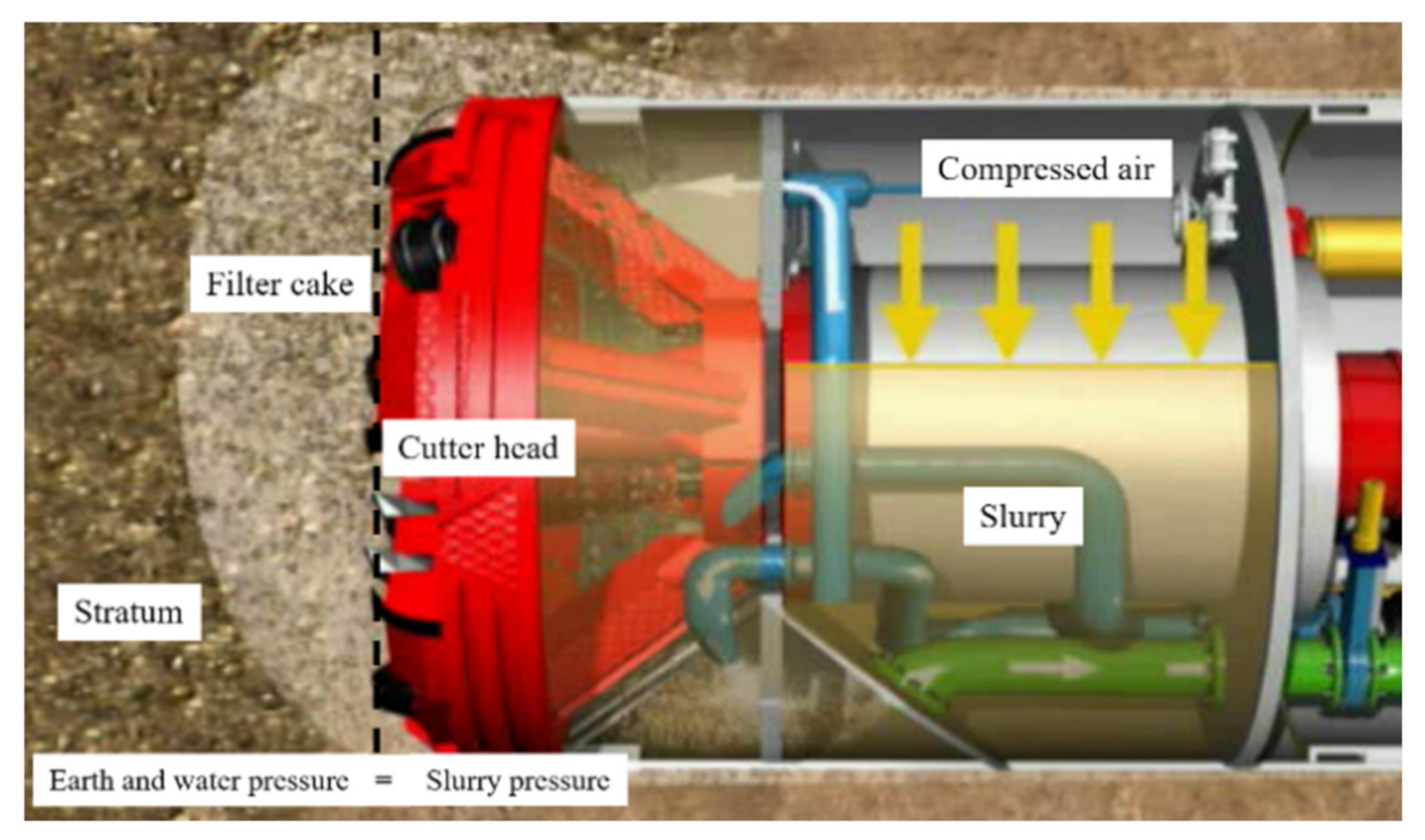
:1. Introduction
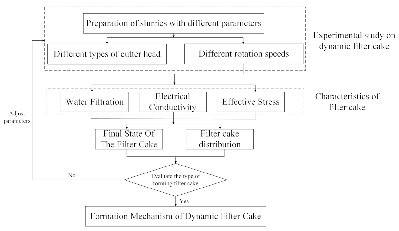
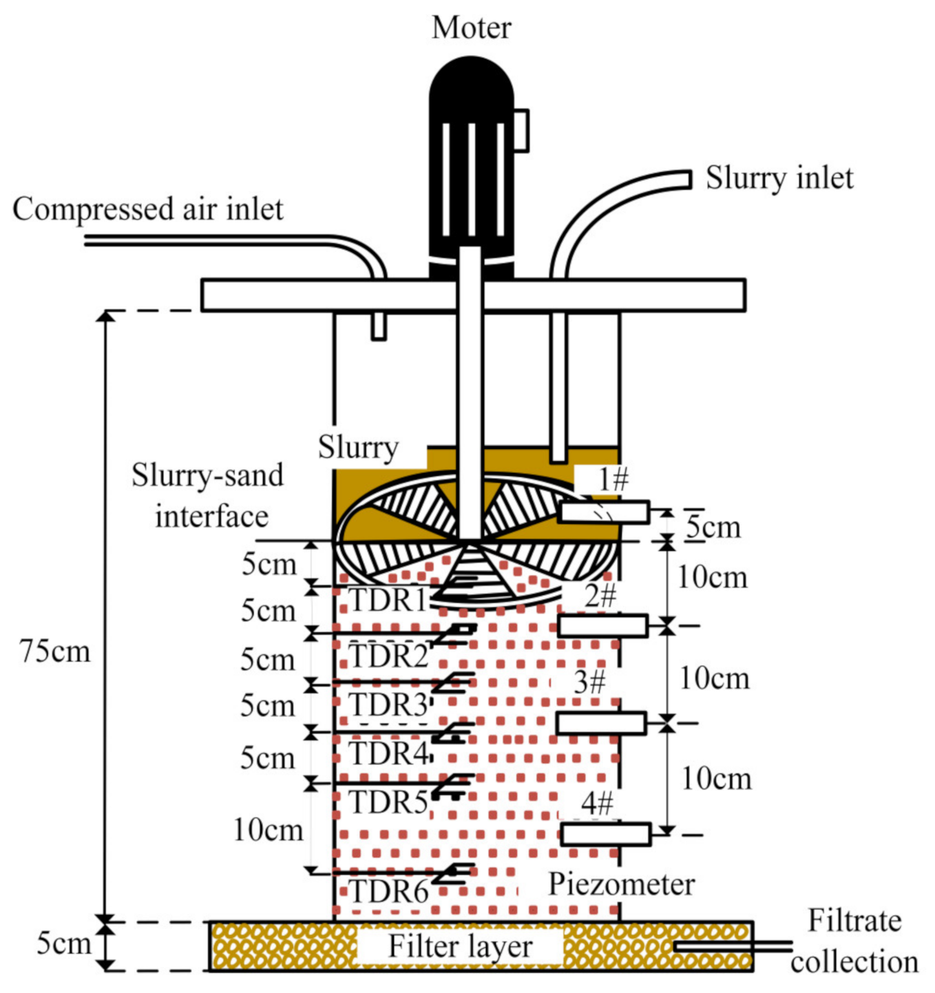
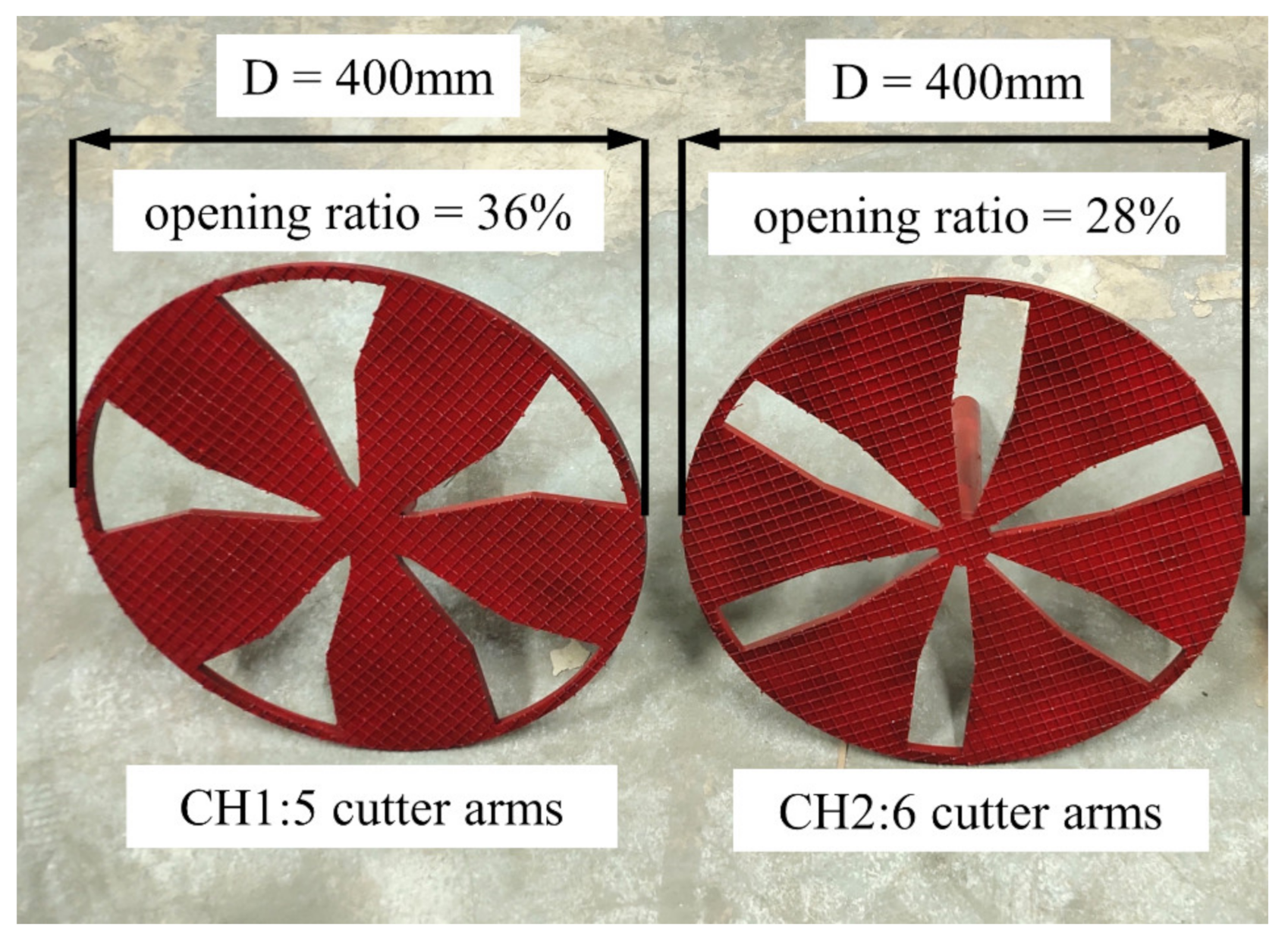
2. Experimental Apparatus and Methods
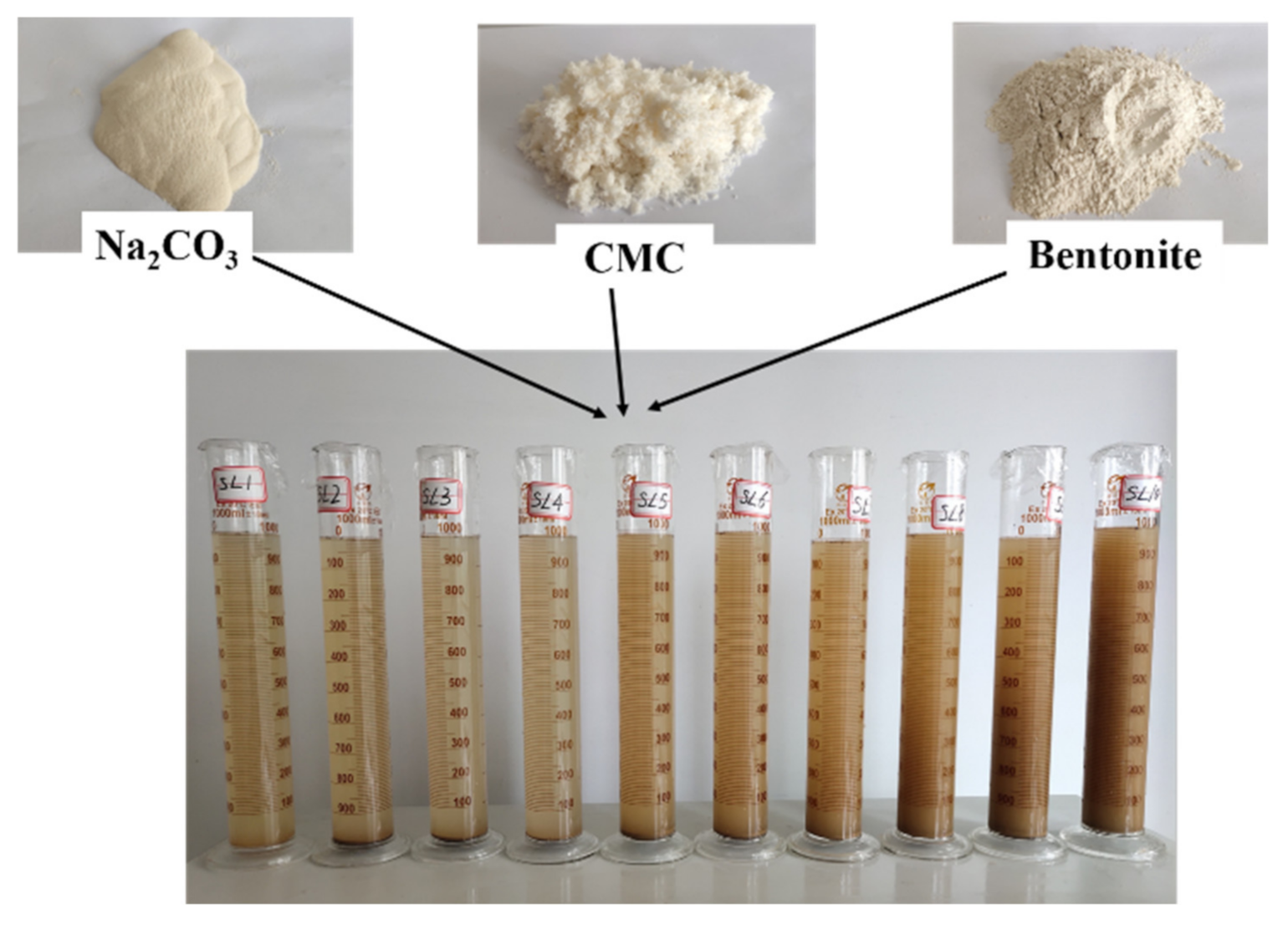
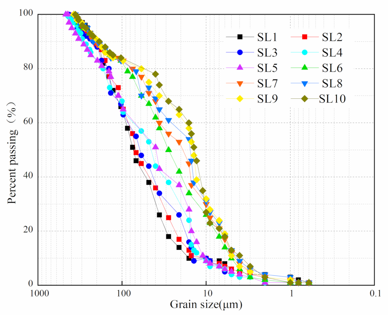
2.1. Test Slurry and Stratum
2.2. Experiment System
2.3. Experiment Conditions and Production Procedure
3. Results and Discussion
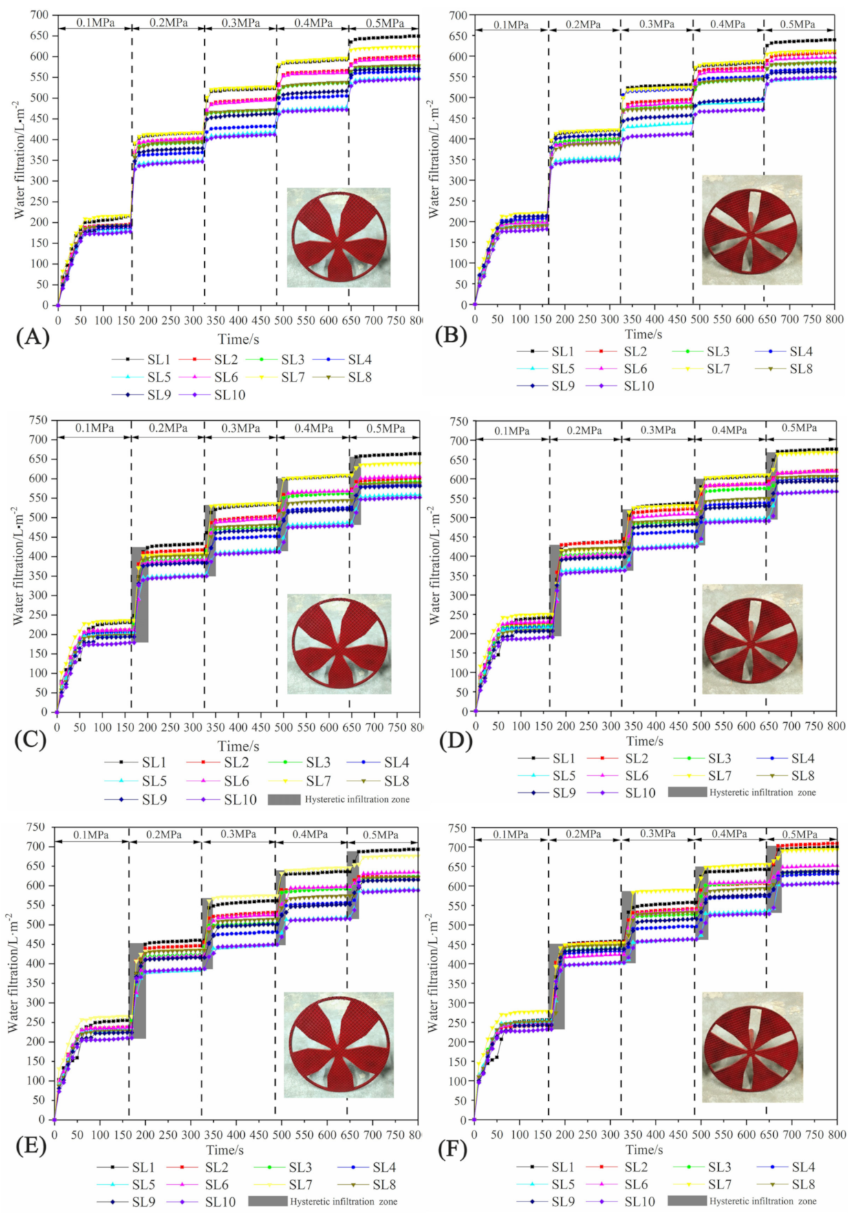
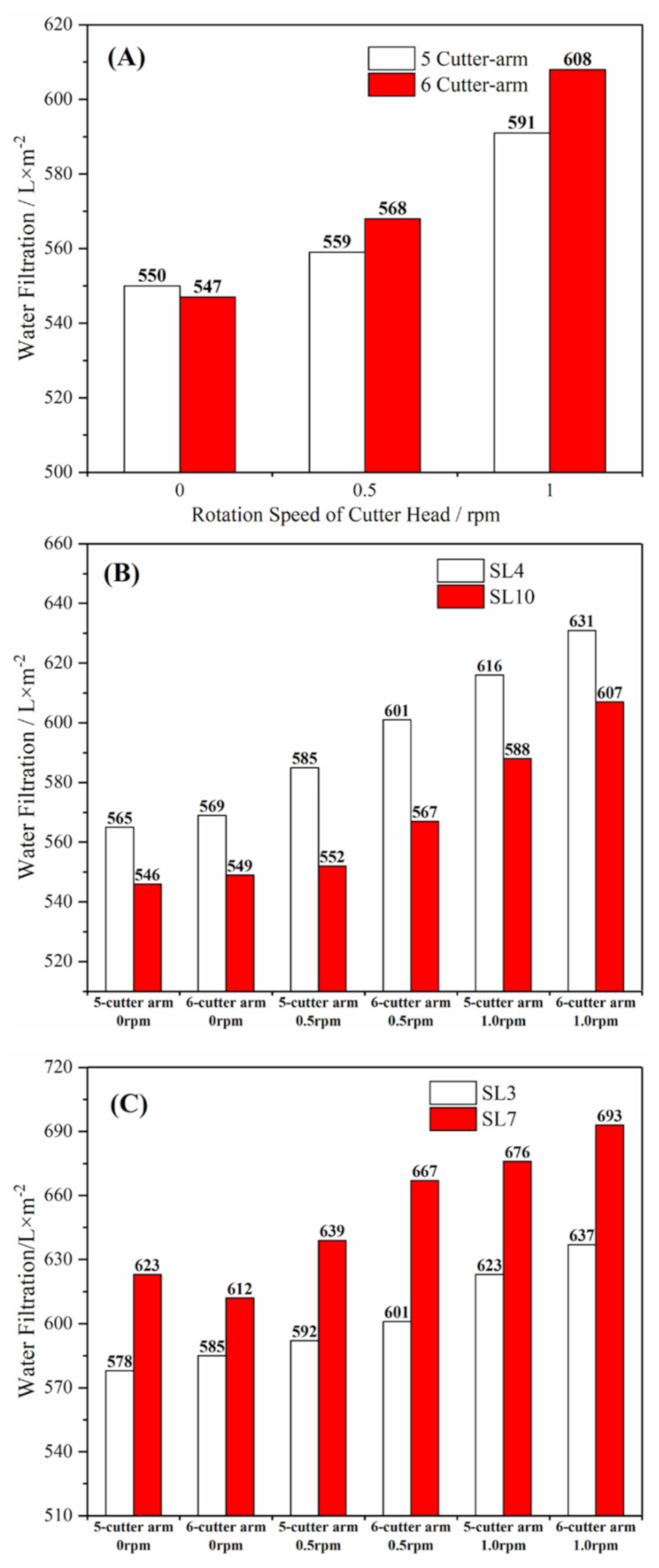
3.1. Water Filtration
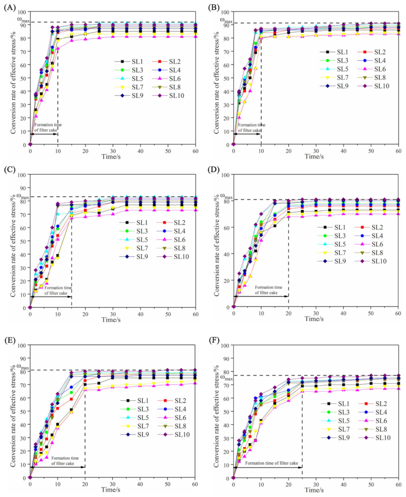
3.2. Effective Stress
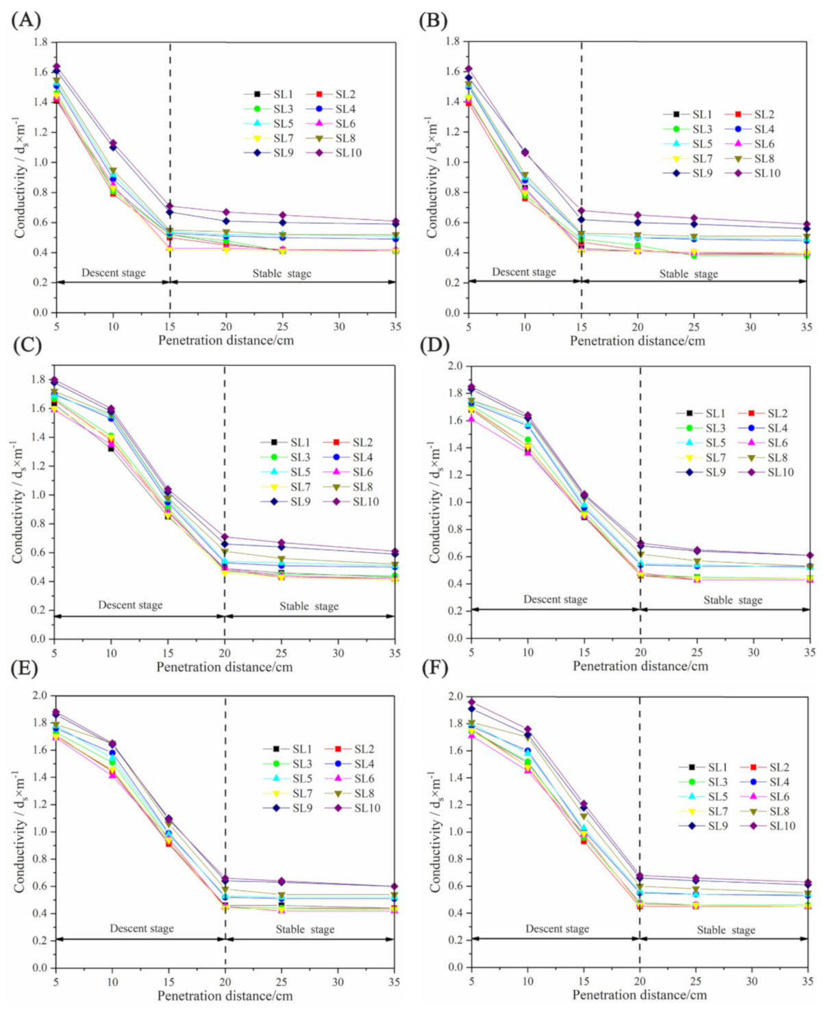
3.3. Electrical Conductivity
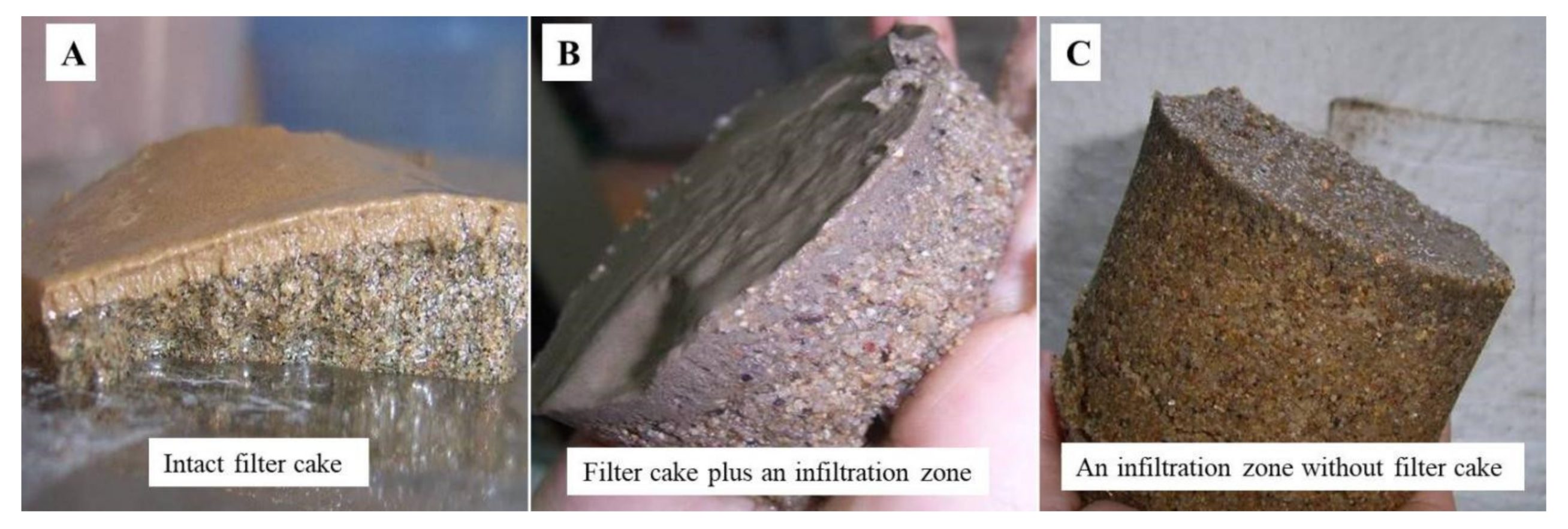
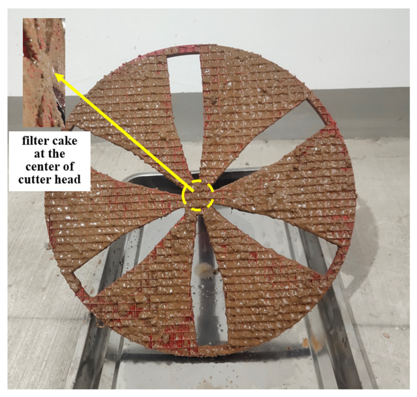
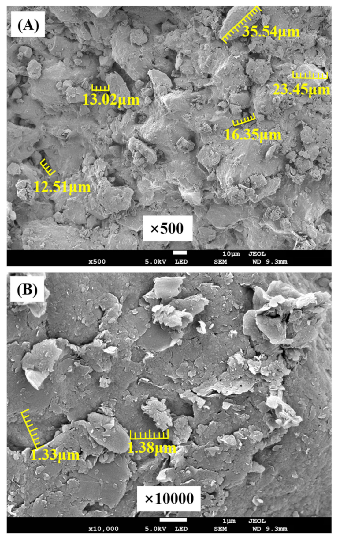
3.4. The Final State of the Filter Cake
4. Discussion
5. Conclusions
- (1)
- Considering the effect of the cutter head structure and rotation, the time curve of water filtration showed a stepped frame distribution, and the filtration volume increased rapidly in the early stage and gradually stabilized in the later stage of the test. The more cutter arms there were and the higher the rotation speed was, the greater the water filtration volume was, decreasing the impermeability of the filter cake.
- (2)
- The variation curve of electric conductivity can be divided into two parts: the descent stage and the stable stage. When the cutter head rotated at 1.0 rpm, the penetration distance of the slurry was 1.5 times that when the cutter head stopped. Moreover, the formation of filter cake with a 6-cutter arm occurred about 5 s later than with the 5-cutter arm.
- (3)
- As the rotation speed of the cutter head increased in saturated sand, the final form of the filter cake transited from a filter cake plus an infiltration zone to an infiltration zone without a filter cake, the thickness of the filter cake decreased continuously, and the filter cake’s permeability increased, which decreased the stability of the excavation face.
- (4)
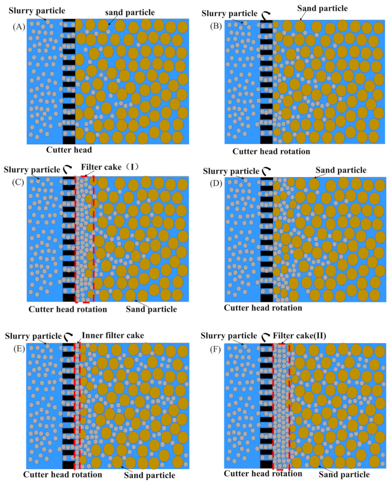
- At the mesoscopic level, the dynamic formation process of the filter cake can be divided into six stages: the initial permeation of slurry particles, large-scale permeation after rotation of the cutter head, the initial formation of the filter cake, the failure of the filter cake, deep permeation of slurry, and the final formation of the filter cake.
Author Contributions
Funding
Data Availability Statement
Acknowledgments
Conflicts of Interest
References
- Broere, W. Urban underground space: Solving the problems of today’s cities. Tunn. Undergr. Space Technol. 2016, 55, 245–248. [Google Scholar] [CrossRef] [Green Version]
- Yuan, D.J.; Shen, X.; Liu, X.Y.; Wu, J. Research on excavation face stability of slurry shield tunneling. China J. Highw. Transp. 2016, 30, 24–37. [Google Scholar]
- Wang, Q. Study on reasonable slurry pressure of excavation face of slurry shield in water rich environment. Highw. Eng. 2019, 44, 151–155. [Google Scholar]
- Zhu, W.; Qian, Y.J.; Min, M.L.; Wang, L.; Wang, C.; Xu, C.; Hu, J.N. The current status and some problems of slurry shield in China. Tunn. Constr. 2019, 39, 724–735. [Google Scholar]
- Liu, G.Y.; Xu, C.; Zhang, Z.Y. Experimental study on slurry performance of slurry balance shield in sandy pebble stratum. Subgrade Eng. 2020, 208, 95–102. [Google Scholar]
- Mo, Z.Z.; Wang, M.S.; Wang, H.B.; Li, H.B.; Qian, Y.J.; Luo, G.D.; Wang, H. Laboratory investigation on pore water pressure variation caused by filter cake effect during slurry-EPB shield tunneling in silty sand layer. Rock Soil Mech. 2019, 40, 2257–2263. [Google Scholar]
- Liu, X.Y.; Wang, F.M.; Yuan, D.J.; Fang, H.Y.; Zhong, S.L. Range of support pressure for slurry shield and its factor analysis. Chin. J. Geotech. Eng. 2018, 41, 908–917. [Google Scholar]
- Qi, W.Q.; Yang, Z.Y.; Jiang, Y.S.; Shao, X.K.; Yang, X.; He, Q. Structural Deformation of Existing Horseshoe-Shaped Tunnels by Shield Overcrossing. KSCE J. Civ. Eng. 2020, 25, 735–749. [Google Scholar] [CrossRef]
- Hong, K.R. Typical underwater tunnels in the mainland of China and related tunneling technologies. Engineering 2017, 3, 871–879. [Google Scholar] [CrossRef]
- Min, F.; Zhu, W.; Han, X. Filter cake formation for slurry shield tunneling in highly permeable sand. Tunn. Undergr. Space Technol. 2013, 38, 423–430. [Google Scholar] [CrossRef]
- Liu, C.; Lu, Y.; Liu, L.; Lv, W.H. Analysis of clogging mechanism and filter-cake structure of slurry containing coarse-particle materials in sandy strata. Mod. Tunn. Technol. 2018, 55, 245–253. [Google Scholar]
- Bai, Y.; Jiang, B.S.; Yang, L.; Ji, X.; Chen, X.X. Experimental study on filter cake formation of large diamater slurry GIL utility tunnel at Sutong. Water Resour. Power 2020, 38, 184–188. [Google Scholar]
- Hernández, Y.Z.; Farfán, A.D.; Assis, A.P. A Three-dimensional analysis of excavation face stability of shallow tunnels. Tunn. Undergr. Space Technol. 2019, 92, 103062. [Google Scholar] [CrossRef]
- Li, L.P.; Shang, C.S.; Chu, K.W.; Zhou, Z.Q.; Song, S.G.; Liu, Z.H.; Chen, Y.H. Large-scale geo-mechanical model tests for stability assessment of super-large cross-section tunnel. Tunn. Undergr. Space Technol. 2021, 109, 103756. [Google Scholar] [CrossRef]
- Chung, J.H.; Daniel, D.E. Modified fluid loss test as an improved measure of hydraulic conductivity for bentonite. Geotech. Test. J. 2019, 31, 243–251. [Google Scholar]
- Horn, N. Horizontal earth pressure on the vertical surfaces of the tunnel tubes. In Proceedings of the National Conference of the Hungarian Civil Engineering Industry, Budapest, Hungary, 18–21 June 1961; pp. 7–16. [Google Scholar]
- Anagnostou, G.; Kovári, K. Face stability condition with earth pressure balanced shields. Tunn. Undergr. Space Technol. 1996, 11, 165–173. [Google Scholar] [CrossRef]
- Broere, W. Influence of excess pore pressures on the stability of the tunnel face. In Claiming the Underground Space; ITA: Amsterdam, The Netherlands, 2003; pp. 759–765. [Google Scholar]
- Zizka, Z.; Schoesser, B.; Thewes, M. Slurry Shield Tunneling: New Methodology for Simplified Prediction of Increased Pore Pressures Resulting from Slurry Infiltration at the Tunnel Face Under Cyclic Excavation Processes. Int. J. Civ. Eng. 2018, 17, 113–130. [Google Scholar] [CrossRef]
- Zumsteg, R.; Puzrin, A.M.; Anagnostou, G. Effects of slurry on stickiness of excavated clays and clogging of equipment in fluid supported excavations. Tunn. Undergr. Space Technol. 2016, 58, 197–208. [Google Scholar] [CrossRef]
- Chen, R.P.; Yin, X.C.; Li, Y.C.; Meng, F.Y.; Sa, C. Permeability of filter cake and its fluence on face stability of slurry shield-driven tunnels. Chin. J. Geotech. Eng. 2017, 39, 2102–2108. [Google Scholar]
- Liu, J.J.; Chen, T.L.; Yao, M.H.; Wei, Y.X.; Zhou, Z.J. Experimental and numerical study on slurry fracturing of shield tunnels in sand stratum. J. Zhejiang Univ. 2020, 54, 1–12. [Google Scholar]
- Jeblli, J.; Meguid, M.A.; Sedghinead, M.K. Excavation failure during micro-tunneling in fine sands. Tunn. Undergr. Space Technol. 2010, 25, 811–818. [Google Scholar] [CrossRef]
- Kim, S.H.; Tonon, F. Face stability and required support pressure for TBM driven tunnels with ideal face membrane-drained case. Tunn. Undergr. Space Technol. 2010, 25, 526–542. [Google Scholar] [CrossRef]
- Zumsteg, R.; Puzrin, A.M. Stickiness and adhesion of conditioned clay pastes. Tunn. Undergr. Space Technol. 2012, 31, 86–96. [Google Scholar] [CrossRef]
- Zhou, Q.H. Analysis of ground disturbance induced by large diameter shield tunneling in silty clay soil. Railw. Stand. Des. 2020, 64, 158–163. [Google Scholar]
- Li, D.; Han, Z.; Sun, X.; Zhou, T.; Li, X. Dynamic Mech anical Properties and Fracturing Behavior of Marble Specimens Containing Single and Double Flaws in SHPB Tests. Rock Mech. Rock Eng. 2019, 52, 1623–1643. [Google Scholar] [CrossRef]
- Li, Y.H.; Liu, D.Z.; Yang, S. Development and application of physical simulation test system for small and medium-sized tunnels based on biaxial motor loading. Chin. J. Geotech. Eng. 2020, 42, 1556–1563. [Google Scholar]
- Fritz, P. Additives for slurry shields in highly permeable ground. Rock Mech. Rock Eng. 2006, 40, 81–95. [Google Scholar] [CrossRef]
- Zdenek, Z.; Britta, S.; Markus, T. Investigations on the transient support pressure transfer at the tunnel face during slurry shield drive Part 2: Case B– Deep slurry penetration exceeds tool cutting depth. Tunn. Undergr. Space Technol. 2021, 118, 104169. [Google Scholar]
- Liu, C.; Tang, X.Y.; Gao, Y.F. Influence of pore characteristics of sand strata on filter cake formation under slurry shield. Chin. J. Geotech. Eng. 2017, 39, 2003–2008. [Google Scholar]
- Xu, T.; Bezuijen, A. Experimental study on the mechanisms of bentonite slurry penetration in front of a slurry TBM. Tunn. Undergr. Space Technol. 2019, 93, 103052. [Google Scholar] [CrossRef] [Green Version]
- Lin, Y.F.; Fang, Y.; He, C.; Wang, W. Experimental study on degree of match between slurry and ground based on particle retention rate. Tunn. Undergr. Space Technol. 2021, 116, 104105. [Google Scholar] [CrossRef]
- Mao, J.H.; Yuan, D.J.; Yang, J.X.; Zhang, B. Theoretical study of porosity characteristic on excavation face of slurry shield in sand stratum. Rock Soil Mech. 2020, 41, 2283. [Google Scholar]
- Zhang, Z.; Yin, T.; Huang, X.; Dias, D. Slurry filtration process and filter cake formation during shield tunneling: Insight from coupled CFD-DEM simulations of slurry filtration column test. Tunn. Undergr. Space Technol. 2019, 87, 64–77. [Google Scholar] [CrossRef]
- Min, F.L.; Du, J.R.; Zhang, N.; Chen, X.G.; Lv, H.J.; Liu, L.C.; Yu, C.J. Experimental study on property change of slurry and filter cake of slurry shield under seawater intrusion. Tunn. Undergr. Space Technol. 2019, 88, 290–299. [Google Scholar] [CrossRef]
- Wei, D.W.; Zhu, W.; Min, F.L. Experimental study of forming time of filter cake and conversion rate of slurry pressure in slurry shield in sand stratum. Rock Soil Mech. 2014, 35, 423–428. [Google Scholar]
- ASTM D2434-06; Standard Test Method for Permeability of Granular Soils. American Society for Testing and Materials: West Conshohocken, PA, USA, 2006.
- Liu, D.S.; Liu, X.R.; Lin, C.Q.; Xiong, F.; Han, Y.F.; Meng, Q.J.; Zhong, Z.L.; Chen, Q.; Weng, C.X. Experimental study and engineering application of slurry permeability mechanism of slurry shield in circular-gravel stratum. Arab. J. Geosci. 2020, 13, 1001–1012. [Google Scholar] [CrossRef]
- Fan, W.C.; Sun, Z.C.; Li, F.Y.; Zhang, B.; Chen, Q.; Wang, F.M.; Wang, K. Research on prediction of tunneling parameters of super-large diameter slurry shield in composite strata of Shantou Bay tunnel. Tunn. Constr. 2020, 40, 1160–1168. [Google Scholar]
- Li, D.Y.; Feng, F.; Li, X. Numerical simulation of rock failure under static and dynamic loading by splitting test of circular ring. Eng. Fract. Mech. 2018, 188, 184–201. [Google Scholar] [CrossRef]


| Test No. | Bentonite Content | Slurry Relative Density | Slurry Viscosity | Clay Content | CMC Content | d85/μm |
|---|---|---|---|---|---|---|
| SL1 | 62 g | 1.05 | 28 s | 60 g | 5 g | 170 |
| SL2 | 62 g | 1.10 | 30 s | 80 g | 6 g | 168 |
| SL3 | 62 g | 1.15 | 30 s | 100 g | 6 g | 173 |
| SL4 | 83 g | 1.20 | 32 s | 120 g | 8 g | 212 |
| SL5 | 83 g | 1.25 | 32 s | 140 g | 8 g | 206 |
| SL6 | 62 g | 1.12 | 22 s | 50 g | 5 g | 140 |
| SL7 | 62 g | 1.15 | 25 s | 100 g | 5 g | 138 |
| SL8 | 83 g | 1.20 | 30 s | 120 g | 5 g | 136 |
| SL9 | 100 g | 1.25 | 30 s | 130 g | 5 g | 135 |
| SL10 | 100 g | 1.28 | 32 s | 150 g | 5 g | 128 |
| Sand No. | Name of Sand | Density | Permeability Coefficient | Internal Friction Angle | Void Ratio |
|---|---|---|---|---|---|
| S1 | Silty–fine sand | 1.45 g/cm3 | 5.7 × 10⁻³ | 31.8° | 0.54 |
| S2 | Medium–coarse sand | 1.86 g/cm3 | 1.08 × 10⁻² | 33.5° | 0.62 |
| Slurry No. | Type of Cutter Head | Rotation Speed of the Cutter Head | ||
|---|---|---|---|---|
| 0 rpm | 0.5 rpm | 1.0 rpm | ||
| SL1 | 5 cutter arms | 6 | 2 | 1 |
| 6 cutter arms | 6 | 2 | 1 | |
| SL2 | 5 cutter arms | 6 | 3 | 2 |
| 6 cutter arms | 6 | 2 | 1 | |
| SL3 | 5 cutter arms | 6 | 3 | 2 |
| 6 cutter arms | 6 | 2 | 1 | |
| SL4 | 5 cutter arms | 7 | 3 | 3 |
| 6 cutter arms | 7 | 3 | 1 | |
| SL5 | 5 cutter arms | 8 | 4 | 3 |
| 6 cutter arms | 8 | 3 | 1 | |
| SL6 | 5 cutter arms | 5 | 2 | 1 |
| 6 cutter arms | 5 | 1 | 1 | |
| SL7 | 5 cutter arms | 6 | 2 | 1 |
| 6 cutter arms | 6 | 2 | 1 | |
| SL8 | 5 cutter arms | 6 | 3 | 2 |
| 6 cutter arms | 6 | 3 | 1 | |
| SL9 | 5 cutter arms | 6 | 4 | 2 |
| 6 cutter arms | 6 | 3 | 1 | |
| SL10 | 5 cutter arms | 9 | 5 | 3 |
| 6 cutter arms | 9 | 5 | 2 | |
Publisher’s Note: MDPI stays neutral with regard to jurisdictional claims in published maps and institutional affiliations. |
© 2022 by the authors. Licensee MDPI, Basel, Switzerland. This article is an open access article distributed under the terms and conditions of the Creative Commons Attribution (CC BY) license (https://creativecommons.org/licenses/by/4.0/).
Share and Cite
Bai, Y.; Jiang, B.; Yang, L.; Liu, Y.; Zheng, H.; Li, Y. Experimental Study on the Characteristics and Formation Mechanism of Dynamic Filter Cake for Slurry Shield Tunneling. Minerals 2022, 12, 331. https://doi.org/10.3390/min12030331
Bai Y, Jiang B, Yang L, Liu Y, Zheng H, Li Y. Experimental Study on the Characteristics and Formation Mechanism of Dynamic Filter Cake for Slurry Shield Tunneling. Minerals. 2022; 12(3):331. https://doi.org/10.3390/min12030331
Chicago/Turabian StyleBai, Yang, Binsong Jiang, Le Yang, Yunqiu Liu, He Zheng, and Yapeng Li. 2022. "Experimental Study on the Characteristics and Formation Mechanism of Dynamic Filter Cake for Slurry Shield Tunneling" Minerals 12, no. 3: 331. https://doi.org/10.3390/min12030331