Article

Pore Structure Characterization of Undisturbed Weathered Crust Elution-Deposited Rare Earth Ore Based on X-ray Micro-CT Scanning

1
Key Laboratory of Ministry of Education for Efficient Mining and Safety of Metal Mines, University of Science and Technology Beijing, Beijing 100083, China
2
School of Civil and Resource Engineering, University of Science and Technology Beijing, Beijing 100083, China
*
Author to whom correspondence should be addressed.
Minerals 2021, 11(3), 236; https://doi.org/10.3390/min11030236
Submission received: 11 December 2020 / Revised: 20 February 2021 / Accepted: 22 February 2021 / Published: 25 February 2021

Abstract

:
As an environmentally compliant hydrometallurgical process, in situ leaching is extensively used by the mining industry to recover rare earth from weathered crust elution-deposited rare earth ore. In the in situ leaching system, the pore structure plays a dominant role in the permeability of the rare earth orebody and is one of the most important factors that influence the leaching performance. To study the pore structure characteristics of the rare earth ore, an undisturbed ore sample was scanned using X-ray micro-computed tomography. Based on the image processing techniques, visualization of the pore structure was realized and several parameters of 2D and 3D pore structures, such as porosity, pore volume, length, width, aspect ratio, and orientation, were obtained and statistically analyzed. The ball-and-stick model of large pore clusters was built by the maximal ball algorithm, and some of their detailed characteristics were obtained. The results indicate that the pore structure of weathered crust elution-deposited rare earth ore exhibits a multi-scale and strong heterogeneity characteristic. The distribution characteristics of pores between the vertical direction and the horizontal direction are obviously different. The small pores are more prevalent in number, but they make only a small contribution to the total pore volume. In addition, the orientation of the pores is anisotropic in both vertical and horizontal directions. Furthermore, the ball-and-stick model reveals that large pore clusters are composed of several interconnected void spaces, and most of them are small and irregular.

1. Introduction

With the rapid development of advanced technologies, the demand for rare earth (RE) is increasing dramatically, especially the middle and heavy rare earth [1,2,3]. Weathered crust elution-deposited rare earth ore, also named ion-adsorption rare earth ore, contains rich middle and heavy rare earth elements (REEs) and is the major source of them in the world [4,5,6]. The REEs in the weathering crust elution-deposited rare earth ore mainly exist as an ion-exchangeable phase adsorbed on clay minerals. Conventional physical processing methods are found to be ineffective in the extraction of rare earths from the weathering crust elution-deposited rare earth ores, but the adsorbed REEs can be leached out by the ion-exchange method [7,8]. After decades of development, three generations of leaching processes have been developed: pool leaching, heap leaching, as well as the in situ leaching process [9]. At present, the in situ leaching technology is widely used to recover REs in the actual mine production because of its advantages in vegetation protection and water–soil conservation [10,11].
In the in situ leaching process, the leaching solutions are directly injected into the orebody, and the lixivium is collected from outlet holes at the foot of the mountain [12]. The leaching solution movement through the weathered crust elution-deposited rare earth orebody is a critical process that provides reactants to and mobilizes products from leaching reactions. Therefore, the flow behavior of leaching solutions in the orebody is the most important factor that affects the recovery ratio and leaching rate of REs [13]. Weathered crust elution-deposited rare earth ore is an unconsolidated porous media. According to the literature, the fluid flow behaviors in porous media are mainly dominated by the microstructure and connectivity of the pore space, which have an important effect on the transport of the solution to value minerals and subsequent leaching and transport to the bulk solution [14,15,16]. In the leaching system, the volume and topological structure of the initial pores determine the generation of preferential flow and leaching blind zone, which further affects subsequent pore evolution and mineral leaching [17,18]. Thus, it is of great significance to investigate the pore structure parameters of weathered crust elution-deposited rare earth ores. There are a few studies on the pore structure of weathered crust elution-deposited rare earth ore. However, these studies mainly focus on the 2D pore structure of the rare earth ore, and the research on the quantitative analysis of the 3D pore structure is insufficient [19,20,21]. In addition, the objects in previous studies were mostly remolded ore samples instead of undisturbed samples, and the result is that the obtained pore structure is not representative of the actual orebody. In this regard, it is necessary to conduct further research on the pore structure characteristics of weathered crust elution-deposited rare earth ore.
In recent years, X-ray micro-computed tomography (micro-CT) has emerged as a powerful non-invasive and nondestructive technique for direct three-dimensional (3D) characterization of the pore structure of porous media [22,23]. This technique is based on the attenuation of radiation by materials of different densities. X-ray micro-CT has been applied to different research areas such as mining engineering, civil engineering, geological engineering, and petroleum engineering [24,25,26]. The combination of X-ray CT data and image processing programs enables us to quantify the pore structure parameters with regard to porosity, pore volume, shape, orientation, and pore size distribution [27]. It has proven successful in studying the pore structure of various porous medias. However, there may be some large pores in the pore space, and they usually have complex shapes. For these pores, the detailed structure characteristics cannot be revealed by such parameters as volume, length, and width. In this case, the pore network model (PNM) approach is used to reveal more detailed information about large pores [28,29,30,31]. The PNM is extracted from the 3D image obtained by CT scanning; the PNM captures the essential characteristics of porous media and preserves the real topological and geometrical properties of the pore space [32,33]. In general, the existing studies provide some valuable guidance on the research of pore structure characteristics of weathered crust elution-deposited rare earth ore.
In this study, the objective was to visualize and characterize the pore structure of weathered crust elution-deposited rare earth ore based on X-ray micro-CT scanning and image processing technology. To ensure that the obtained pore structure of the specimen is consistent with the actual ore body, an undisturbed rare earth ore sample was used for CT scanning. A series of parameters of the 2D/3D pore structure, such as porosity, pore volume, length, width, aspect ratio, and orientation, were statistically characterized and analyzed. Furthermore, some detailed characteristics of large pore clusters were obtained by ball-and-stick models, which were extracted from the reconstructed 3D pore images by the maximal ball algorithm.

2. Materials and Methods

2.1. Ore Sample

The weathered crust elution-deposited rare earth ore sample studied in this work was taken from Longnan County, Jiangxi Province, China; this sample is mainly composed of clay minerals and quartz. The sample was collected vertically from the completely weathered layer of the orebody, at a 4.6 m depth, by a special sampling device. After sampling, the ore sample was sealed in a cylindrical container to keep the internal structure in its original condition. The particle size distribution was measured by the wet-sieving method, and the result is shown in Figure 1. It was found that most of the particles in rare earth ore are between 0.2 and 5 mm in size.

2.2. X-ray Micro-CT Scanning

In this study, the ore sample was imaged using a Nano Voxel-4000 X-ray 3D microscope (Sanying Precision Instruments Co., Ltd, China), as shown in Figure 2a. The scanning area of the experimental sample is shown in Figure 2b, the diameter of the sample (including the container) was 75 mm, and the height of scanning area was about 61 mm. Before conducting the CT scan, the scanning parameters and conditions were calibrated and set to obtain high-resolution images and reduce the noise and artifacts during the image acquisition process. The bright-field correction and dark-field correction were used in the measurement. In the scanning process, the rare earth ore sample was scanned at a voltage of 160 kV and an operating current of 125 μA; the exposure for each projection was 0.6 s, and the spatial resolution was 42.02 μm/voxel. The sample was scanned by a cone beam, and the beam angle was 30°. The detector used for the test was a flat panel detector; its main parameters were as follows: pixel matrix, 1920 × 1536 pixels; pixel pitch, 127 μm; pixel area, 244 mm × 195 mm. In this study, no filter was used during the CT scanning because the voltage selected for X-rays was sufficient to penetrate the sample. The scanning rate was 0.25°/unit amplitude, and a total of 1440 projections were obtained. Projection averaging was used during the CT scanning; two projected images were collected at each rotation angle and then averaged. Reconstruction of datasets with the reconstruction software VoxelStudiorecon followed image acquisition, using the FDK reconstruction algorithm [34]. It was noted that before the 3D image reconstruction, the beam hardening correction of CT datasets was performed, also using VoxelStudiorecon. The resulting 3D image contained 1450 slices (images), and each image contained 1900 × 1900 pixels. The CT images were encoded with 16-bit precision corresponding to a gray-scale level of 0–65,535 in order to avoid compression of the gray-scale histogram.

2.3. Image Processing

Accurate image processing directly determines the accuracy of pore extraction [35]. After reconstruction, the dataset was loaded into Avizo software for further image processing and analysis. Avizo is an advanced image processing software (FEI, Hillsboro, OR, USA), and it is widely used in pore structure extraction and analysis [36,37,38]. Figure 3a shows the raw CT image. The raw images obtained by the micro-CT scanning usually comprise a certain level of noise, which has a significant negative effect on the quality of segmentation. So, it is necessary to conduct filtration on the original images. In this study, a non-local means filter (local neighborhood of 5 pixels and similarity value of 0.6) was applied to reduce the noise and improve the image quality. Figure 3b shows the filtered CT image; it can be seen that the non-local means filter can effectively eliminate the noise in a gray image. As shown in Figure 3a, the boundary of the raw sample is irregular and it causes some inconvenience for subsequent pore structure characterization. Therefore, the region of interest (ROI) was extracted from the center of the 3D scanned volume. Figure 3d shows the ROI within the complete sample. The size of the ROI was 1000 × 1000 × 1000 voxels, equivalent to 42.02 × 42.02 × 42.02 mm3.
After the completion of image filtering and ROI extraction, the image segmentation process was implemented. Segmentation of different components into each phase was possible based on their attenuation coefficient, which depends upon the material density and atomic number. The attenuation coefficient is expressed as a gray-scale value, so the components with different densities in the sample are represented by different gray-scale values (or value ranges) in CT images [39]. Figure 3c shows the histogram of the filtered 3D image. Because of their difference in density, pores can be easily segmented from the solid phase of the rare earth ore by a global thresholding technique. Based on the gray-scale intensity histogram, threshold segmentation of the rare earth ore sample’s 3D image was carried out by Avizo software. The 2D slices were also visually inspected to verify the quality of the segmentation procedure. This resulted in binary label data, in which pores are labeled as 1 and the solid matrix as 0. Figure 3e shows the pore distribution in the ROI. The 3D volume rendering of the extracted pore structure is shown in Figure 3f, and it can be seen that the structure of pore space in rare earth ore is characterized by tortuous and strong heterogeneities. Subsequently, the pore structure parameters such as porosity, pore volume, length, width, and orientation of individual pores were determined using Avizo.

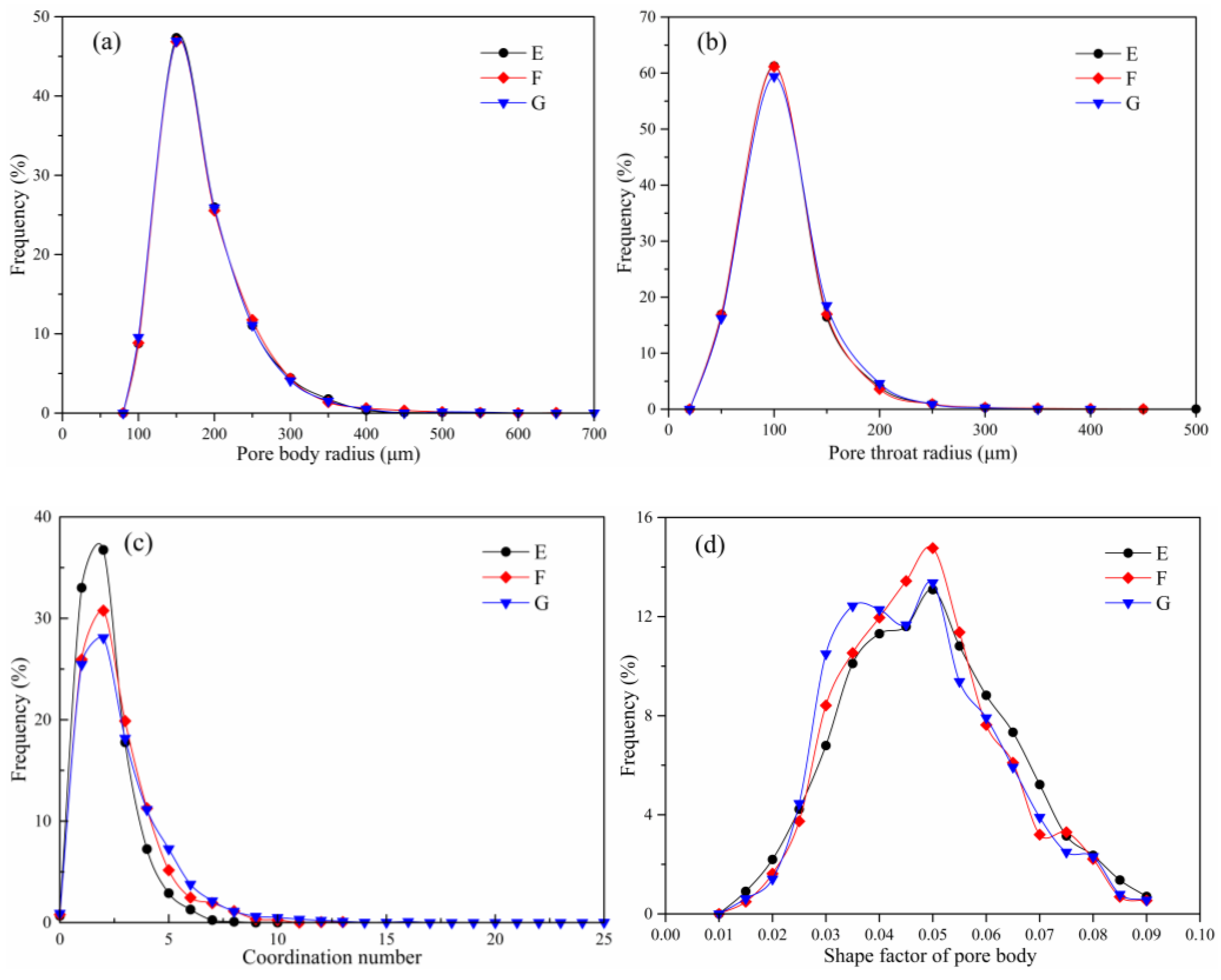
3. Results and Discussion

3.1. 2D Pore Structure

3.1.1. Pore Area

All the individual 2D pores in the XY, XZ, and YZ directions of the ROI were identified, and the parameters of each pore were calculated using the Label Analysis module in Avizo. To reduce the analysis error, the pores with the volume of one voxel were removed from the pore space. In this study, the pores that did not contact each other on the 2D cross section were defined as 2D individual pores. According to the statistics, there are 661,227, 666,557, and 460,378 individual pores in the YZ, XZ, and XY directions, respectively. Figure 4 shows the distribution of pores on the cross sections in different directions, and the colored areas in the figure represent the pores. Some pores are shown in the same color because of the limitation of the colormap. It can be seen that the 2D pores in all three directions have a broad size range, and most of the pore shapes are not circular.
In view of the irregular shape of the pores, the pore area was utilized to describe the size of pores, which refers to the area of a single 2D pore. The distributions of the pore area in three directions were calculated in both frequency and cumulative frequency, as presented in Figure 5. To enhance the presentation of the results, the distribution range of the pore area was rescaled to the logarithmic axis [40]. It was found that in all three directions, the pore areas are between 103.2 and 107.4 μm2 and more than 92% of the pore areas are smaller than 105.6 μm2. Accordingly, as shown in Figure 5, the pores with an area between 104.4 and 104.7 μm2 are the largest pore population in every direction and account for 17.02%, 16.91%, and 16.93% of the total number of pores in the YZ, XZ, and XY directions, respectively. Furthermore, in the YZ, XZ, and XY directions, the average 2D pore areas are 91,689, 90,956, and 131,690 μm2, respectively, and the number of pores that have an area less than the average pore area accounts for 77.16%, 77.29%, and 75.60%, respectively. This indicates that most 2D pores in rare earth ore are small pores. There is no obvious difference between the XZ and YZ directions, but the number of pores with an area larger than 104.7 μm2 in the XY direction is significantly greater than that in the XZ and YZ directions. The results of the pore area analysis show that the pores of weathered crust elution-deposited rare earth ore are non-uniformly distributed in three directions, and the 2D pores in the XY direction are larger than those in the XZ and YZ directions. It means that the pore space of rare earth ore has relatively good connectivity in the XY direction (vertical direction).

3.1.2. Pore Length and Width

In this study, the pore size was characterized using Feret’s diameter, of which the maximum was defined as the pore length and the minimum as the pore width [41]. The statistical results of the length and width of 2D pores in three directions are shown in Figure 6. Similar to the distribution of the pore area, the frequency distribution of the pore length and width in the XZ direction is basically consistent with that in the YZ direction. It can be seen from Figure 6a that in all three directions, the majority of the pore lengths lie in 101.9–103.1 μm, and the frequency of corresponding pores in the XY, XZ, and YZ directions is 89.50%, 89.55%, and 89.60%, respectively. In the YZ, XZ, and XY directions, the average pore lengths are 423.83, 423.92, and 518.08 μm, respectively. In all directions, more than 66% of the pore lengths are less than the average length. Accordingly, as shown in Figure 6b, the majority of the pore widths are less than 102.8 μm, which have the frequencies of 92.17%, 95.35%, and 95.24% for pores in the XY, XZ, and YZ directions, respectively.

3.1.3. 2D Aspect Ratio

In the former analysis, the shape of pores is very complex, and only a few of them appear as sub-orbicular, and most of them are irregular. A quantitative assessment of the 2D pore shapes could provide a better insight into the pore structures of rare earth ore. According to the literature, the pore shape could be explained by the aspect ratio, which is defined as the ratio of length to width for each pore [42]. Statistics show that the ranges of the aspect ratio in the XY, XZ, and YZ directions are 1–15, 1–20, and 1–17, respectively. The distribution curves of the aspect ratio of pores in three directions are shown in Figure 7. It can be seen that the distributions of the 2D pore aspect ratio in all three directions have positive skewness, and the maximum range is 1.5–2. Furthermore, as shown in Figure 7, the aspect ratios of most pores are large than 1.5, and the proportions of corresponding pores in the XY, XZ, and YZ directions are 67.04%, 69.02%, and 69.14%, respectively. It indicates that the shapes of most 2D pores are not block-like but strip-like.

3.1.4. 2D Porosity

The ratio of the area of pores to the total area of the CT image was used to characterize the 2D porosity of the ROI [43]. Figure 8 is the 2D porosity distribution along the X, Y, and Z axes of the ROI, and the data processing and analysis results are listed in Table 1. As shown in Figure 8, the distribution form of the 2D porosity along the X axis is similar to that along the Y axis and presents an inverse C shape. However, the distribution of the 2D porosity along the Z axis is contrary to that along the X and Y axes, and it appears as a C shape. As shown in Table 1, the variance of the 2D porosity in the X axis direction is higher than that in the other two directions. The fluctuation amplitude of the 2D porosity in the X axis direction is greater than that in the Y and Z axis directions. These results indicate that the distribution of the 2D porosity in three directions of rare earth ore is extremely non-uniform, and the difference between different directions is significant.

3.2. 3D Pore Structure

3.2.1. 3D Pore Volume

The independent pores in the 3D pore space were separated using Avizo, and then the individual pores were analyzed. In this study, the group of voxels that are connected by at least one common vertex was treated as an individual pore. In addition, the pores with the volume of one voxel were removed from the pore space when the 3D pore structure analysis was performed; it is consistent with the 2D pore analysis. Figure 9 shows the 3D volume rendering of separated pores of the ROI. Some separate pores are shown in the same color because of the limitation of the colormap. As illustrated in Figure 9, the 3D pore space of weathered crust elution-deposited rare earth ore is composed of many independent pores. According to statistics, the 3D porosity of the ROI is 3.43%, the volumes of all independent pores are in the range of 148,388–1·1012 μm3, and the volume of the largest pore cluster is about 4.52·1011 μm3. The data indicate that the pore structure of weathered crust elution-deposited rare earth ore has a multi-scale characteristic.
The distribution of pore volumes was calculated in both count frequency and volume fraction, as presented in Figure 10. It can be found that the pore number increases first and then decreases as the pore volume increases. Furthermore, although the smaller pores are more prevalent in number, they make only a small contribution to the total pore volume. The rare large pores dominate the total volume. As shown in Figure 10, the number of pores with volume less than 108 μm3 constitute 95.13% of the total pore number, but their cumulative volume accounts for only 16.28% of the total pore volume. For a better understanding of the characteristics of pores at different scales, the pore clusters were divided into seven groups based on the pore volume, as presented in Table 2, and the 3D volume rendering image of each group is shown in Figure 11. It is clear that with the increase in the pore volume (groups A to G), the complexity and irregularity of the pore geometry increase, and the relatively large pore clusters (groups E–G) have stick-like and root-like morphologies.

3.2.2. 3D Pore Length and Width

The length and width of each independent 3D pore were calculated based on Feret’s diameter. According to statistics, the length of pores varies from 87 to 50,274 μm and the width from 46 to 28,096 μm. The distributions of the length and width of pores are shown in Figure 12. It can be observed that 85.14% of the frequency of all pore lengths lies in the range of 100–1000 μm, and the majority of the pore widths vary between 101.6 and 102.6 μm in size, with a relative frequency of 89.49%. In Figure 13, the distribution of the aspect ratio is presented; it can be found that the number of pores with aspect ratio greater than 2 accounts for 60.86%. This result indicates that only a very small percentage of the pores is block-like, and the shapes of the majority of pores are very complex, which is consistent with the pore characteristics illustrated in Figure 11.
The pore aspect ratios of each group in Table 2 were calculated respectively, and the results are shown in Table 3. It can be found that the value of the minimum aspect ratio of pores increases with the increase in the pore volume. With an increase in the order of the pore volume, the average aspect ratio and the maximum aspect ratio both increased first and then decreased. The variation characteristic of the pore aspect ratio is consistent with the variation in the pore shape, as shown in Figure 11. The results imply that as the pore volume increases, the pore shape changes from block-like to strip-like and then to root-like or net-like.

3.2.3. Pore Orientation

The anisotropy of the pore structure was evaluated by measuring the pore orientation (direction of the long axis of a pore) in a spherical coordinate system. The pore orientation can be defined by the azimuthal angle θ and polar angle φ. The azimuthal angle θ is the angle between the projection of the pore orientation over the XY plane (measured between 0° and 360°), while the polar angle φ is the angle between the pore orientation with the Z axis (measured between 0° and 90°) [40]. In this study, pores with equal length and width and the volume of one voxel were removed from the total pores.
From the rose plot of the two parameters shown in Figure 14, approximately 68.43% of the orientation φ is in the range of 70–90°. This shows that the pore orientation of the sample is prone to the horizontal. With regard to the orientation θ, Figure 14 demonstrates that there is a relatively even distribution in the XY plane based on the frequency rose plot, only showing a little preference at 120–130° and 230–240°. It can be found that the azimuth angle of the pores in rare earth ore shows more significant anisotropy than the polar angle.

3.2.4. Analysis of a Large Pore Cluster

Pore shapes become more complex and irregular with an increase in the pore volume, and their detailed structure characteristics cannot be revealed by parameters such as volume, length, and width. Instead, the pore network model can reveal more detailed information about the pore architecture and avoid the incompetency in the volume, length, and width method in analyzing the pore throat parameters in connected pore clusters.
It can be seen from Figure 11 that the shapes of pores in groups E–G are significantly more complex than those in the other four groups. Therefore, to obtain the detailed structure characteristics of the connected pore clusters, pore network model analysis was carried out for the large pore clusters shown in Figure 11E–G. The ball-and-stick models of groups E–G were extracted from the reconstructed 3D binary pore images by using the maximal ball algorithm respectively. The results are shown in Figure 15. In ball-and-stick models, large void spaces are referred to as pore bodies and the narrow paths connecting two pore bodies are referred to as throats. Pore bodies are represented by balls, and pore throats are represented by sticks. The details regarding the maximal ball algorithm can be found in Raeini et al. [44]. The pore structure parameters such as pore body and pore throat radius, coordination number, and pore shape factor were obtained, and the distribution of each parameter is shown in Figure 16.
It can be seen from Figure 15 that the large pore clusters are composed of several interconnected pore spaces, and the difference between these pore spaces increases along with an increase in the pore cluster volume. As shown in Figure 16a,b, the pore body radius and pore throat radius of the three groups of pore clusters have a positively skewed distribution. In all three ball-and-stick models, the radii of most pore bodies are less than 250 μm, and the radius of most pore throats is less than 150 μm. The coordination number is referred to as the number of neighboring pore bodies connected to a given pore body, and the larger the coordination number, the better the connectivity. As can be seen in Figure 16c, the maximum coordination number of groups E–G is 11, 13, and 25, respectively. Furthermore, with an increase in the pore cluster volume, the amount of high-coordination pore bodies in the corresponding ball-and-stick model increases. The shape factor is used to quantitatively evaluate the shape of the pore spaces that make up the pore clusters, and the definition of the pore shape factor can be found in Bultreys et al. [45]. In Figure 16d, it can be found that the distribution of the shape factor is similar for all three groups, and the main distribution values are 0.030–0.055, 0.030–0.055, and 0.025–0.050, respectively. According to Tang et al. [30], the larger the value of the form factor, the more regular the shape. Hence, the shape of most pore spaces that make up the large pore clusters is irregular.
Pore network model analysis reveals that large pore clusters are composed of several interconnected small pores. To further analyze the connectivity differences between pores of different volumes, the average coordination number of pores in groups A to G was calculated. Due to the small number of voxels contained in each pore in group A, no effective pore network model parameters were obtained, and the coordination number of group A could be regarded as 0. For groups B to G, their average coordination numbers are 0.17, 0.22, 1.27, 2.14, 2.62, and 2.85, respectively. This indicates that pore connectivity increases with an increase in the pore volume.

4. Conclusions

In this study, the pore structure of undisturbed weathered crust elution-deposited rare earth ore was semi-quantitatively characterized based on the X-ray micro-CT scanning and image processing technology. The visualization of the pore structure was realized, and the distribution characteristics of 2D/3D pore parameters were analyzed. The main conclusions are summarized as follows:
(1) The 2D pores in the sample have a broad size range, and most 2D pores in the rare earth ore sample are small pores. That is, most of the solution seepage channels in undisturbed weathered crust elution-deposited rare earth ore are narrow. Furthermore, the pores in the sample are non-uniformly distributed in all directions, and there are obvious differences in the vertical and horizontal directions. The 2D pore distribution characteristics indicate that the solution flows in different directions of the orebody are heterogeneous.
(2) The 3D pore structure of undisturbed weathered crust elution-deposited rare earth ore has significant multi-scale characteristics, and its connectivity is poor. The smaller pores are more prevalent in number, but they make only a small contribution to the total pore volume. As the pore volume increases, the pore shape becomes more complex. The small pores are strip-like, and the large pores are root-like or net-like. The orientation of pores is anisotropic in both vertical and horizontal directions.
(3) The results of 2D and 3D pore analyses are mutually verified and supplemented. The 2D pore analysis reveals the difference of the pore structure distribution between the vertical and horizontal directions. The 3D pore analysis shows the connectivity and structural characteristics in the pore space.
(4) The combination of micro-CT scanning and image processing is an effective method to visualize the pore structure of rare earth ore. The scanning resolution is the key factor affecting the lower boundary of the pore size, and some pores smaller than the achieved resolution cannot be identified. In the next research, it is necessary to study samples of different sizes so as to further analyze the multi-scale characteristics of pore structures in rare earth ore.

Author Contributions

Conceptualization, S.Y. and X.C.; methodology, X.C.; software, X.C.; formal analysis, X.C.; investigation, R.Y.; resources, S.Y.; writing—original draft preparation, S.Y. and X.C.; writing—review and editing, X.C. and L.W.; visualization, X.C.; funding acquisition, S.Y. All authors have read and agreed to the published version of the manuscript.

Funding

This research was funded by the Key Program of the National Natural Science Foundation of China (grant numbers 51734001, 52034001) and the Fundamental Research Funds for the Central Universities (grant number FRF-TP-18-003C1).

Institutional Review Board Statement

Not applicable.

Informed Consent Statement

Not applicable.

Data Availability Statement

Not applicable.

Acknowledgments

The authors would like to thank Sanying Precision Instruments Co., Ltd for providing the Avizo software.

Conflicts of Interest

The authors declare no conflict of interest.

References

  1. Goodenough, K.M.; Wall, F.; Merriman, D. The Rare Earth Elements: Demand, Global Resources, and Challenges for Resourcing Future Generations. Nat. Resour. Res. 2018, 27, 201–216. [Google Scholar] [CrossRef] [Green Version]
  2. Tang, J.; Qiao, J.Y.; Xue, Q.; Liu, F.; Chen, H.H.; Zhang, G.C. Leach of the weathering crust elution-deposited rare earth ore for low environmental pollution with a combination of (NH4)2SO4 and EDTA. Chemosphere 2018, 199, 160–167. [Google Scholar] [CrossRef]
  3. Wang, X.B.; Lei, Y.L.; Ge, J.P.; Wu, S.M. Production forecast of China’s rare earths based on the generalized Weng model and policy recommendations. Resour. Policy 2015, 43, 11–18. [Google Scholar] [CrossRef] [Green Version]
  4. Tian, J.; Yin, J.Q.; Chen, K.H.; Rao, G.H.; Jiang, M.T.; Chi, R.A. Optimisation of mass transfer in column elution of rare earths from low grade weathered crust elution-deposited rare earth ore. Hydrometallurgy 2010, 103, 211–214. [Google Scholar]
  5. Xiao, Y.F.; Huang, L.; Long, Z.Q.; Feng, Z.Y.; Wang, L.S. Adsorption ability of rare earth elements on clay minerals and its practical performance. J. Rare Earths 2016, 34, 543–548. [Google Scholar] [CrossRef]
  6. Xiao, Y.F.; Feng, Z.Y.; Hu, G.H.; Huang, L.; Huang, X.W.; Chen, Y.Y.; Long, Z.Q. Reduction leaching of rare earth from ion-adsorption type rare earths ore with ferrous sulfate. J. Rare Earths 2016, 34, 917–923. [Google Scholar] [CrossRef]
  7. Tian, J.; Yin, J.Q.; Chi, R.A.; Rao, G.H.; Jiang, M.T.; Ouyang, K.X. Kinetics on leaching rare earth from the weathered crust elution-deposited rare earth ores with ammonium sulfate solution. Hydrometallurgy 2010, 101, 166–170. [Google Scholar]
  8. Yin, S.H.; Pei, J.N.; Jiang, F.; Li, S.W.; Peng, J.H.; Zhang, L.B.; Ju, S.H.; Srinivasakannan, C. Ultrasound-assisted leaching of rare earths from the weathered crust elution-deposited ore using magnesium sulfate without ammonia-nitrogen pollution. Ultrason. Sonochem. 2018, 41, 156–162. [Google Scholar] [CrossRef] [PubMed]
  9. Huang, X.W.; Long, Z.Q.; Li, H.W.; Ying, W.J.; Zhang, G.C.; Xue, X.X. Development of rare earth hydrometallurgy technology in China. J. Rare Earths 2005, 23, 1–4. [Google Scholar] [CrossRef]
  10. Yang, X.J.; Lin, A.J.; Li, X.L.; Wu, Y.D.; Zhou, W.B.; Chen, Z.H. China’s ion-adsorption rare earth resources, mining consequences and preservation. Environ. Dev. 2013, 8, 131–136. [Google Scholar] [CrossRef]
  11. Zhang, Z.Y.; He, Z.Y.; Yu, J.X.; Xu, Z.G.; Chi, R.A. Novel solution injection technology for in-situ leaching of weathered crust elution-deposited rare earth ores. Hydrometallurgy 2016, 164, 248–256. [Google Scholar] [CrossRef]
  12. Zhou, F.; Liu, Q.; Feng, J.; Su, J.X.; Liu, X.; Chi, R.A. Role of initial moisture content on the leaching process of weathered crust elution-deposited rare earth ores. Sep. Purif. Technol. 2019, 217, 24–30. [Google Scholar] [CrossRef]
  13. He, Z.Y.; Zhang, Z.Y.; Chi, R.A.; Xu, Z.G.; Yu, J.X.; Wu, M.; Bai, R.Y. Leaching hydrodynamics of weathered elution-deposited rare earth ore with ammonium salts solution. J. Rare Earths 2017, 35, 824–830. [Google Scholar] [CrossRef]
  14. Yang, B.H.; Wu, A.X.; Miao, X.X.; Liu, J.Z. 3D characterization and analysis of pore structure of packed ore particle beds based on computed tomography images. Trans. Nonferrous Met. Soc. China 2014, 24, 833–838. [Google Scholar] [CrossRef]
  15. Ram, R.; Beiza, L.; Becker, M.; Pownceby, M.I.; Chen, M.; Yang, Y.; Yang, S.; Petersen, J. Study of the leaching and pore evolution in large particles of a sulfide ore. Hydrometallurgy 2020, 192, 105261. [Google Scholar] [CrossRef]
  16. Menke, H.P.; Bijeljic, B.; Blunt, M.J. Dynamic reservoir-condition microtomography of reactive transport in complex carbonates: Effect of initial pore structure and initial brine pH. Geochim. Cosmochim. Acta 2017, 204, 267–285. [Google Scholar] [CrossRef] [Green Version]
  17. Kartha, S.A.; Srivastava, R. Slow and Fast Transport in Heap Leaching of Precious Metals. Transp. Porous Med. 2012, 94, 707–727. [Google Scholar] [CrossRef]
  18. Yang, B.H.; Wu, A.X.; Wang, C.L.; Niu, W.X.; Liu, J.Z. Three-dimensional simulation of pore scale fluid flow in granular ore media with realistic geometry. Trans. Nonferrous Met. Soc. China 2012, 22, 3081–3086. [Google Scholar] [CrossRef]
  19. Wang, X.J.; Li, Y.X.; Huang, G.L.; Deng, S.Q.; Xiao, W.J.; Liao, S.Y. Changes of pore structure in leaching ion-adsorption type rare earth ore. J. Chin. Rare Earth Soc. 2017, 35, 528–536. (In Chinese) [Google Scholar]
  20. Zhao, K.; Zhuo, Y.L.; Wang, X.J.; Zhong, W. Aggregate Evolution Mechanism during Ion-Adsorption Rare Earth Ore Leaching. Adv. Mater. Sci. Eng. 2018, 2018, 4206836. [Google Scholar] [CrossRef] [Green Version]
  21. Zhou, L.B.; Wang, X.J.; Zhuo, Y.L.; Hu, K.J.; Zhong, W.; Huang, G.L. Dynamic pore structure evolution of the ion adsorbed rare earth ore during the ion exchange process. R. Soc. Open Sci. 2019, 6, 191107. [Google Scholar] [CrossRef]
  22. Cnudde, V.; Boone, M.N. High-resolution X-ray computed tomography in geosciences: A review of the current technology and applications. Earth-Sci. Rev. 2013, 123, 1–17. [Google Scholar] [CrossRef] [Green Version]
  23. Schmitt, M.; Halisch, M.; Muller, C.; Peres Fernandes, C. Classification and quantification of pore shapes in sandstone reservoir rocks with 3-D X-ray micro-computed tomography. Solid Earth 2016, 7, 285–300. [Google Scholar] [CrossRef] [Green Version]
  24. Dhawan, N.; Safarzadeh, M.S.; Miller, J.D.; Moats, M.S.; Rajamani, R.K.; Lin, C.L. Recent advances in the application of X-ray computed tomography in the analysis of heap leaching systems. Miner. Eng. 2012, 35, 75–86. [Google Scholar] [CrossRef]
  25. Yio, M.H.N.; Wong, H.S.; Buenfeld, N.R. 3D pore structure and mass transport properties of blended cementitious materials. Cem. Concr. Res. 2019, 117, 23–37. [Google Scholar] [CrossRef]
  26. Musso, A.; Lamorski, K.; Sławiński, C.; Geitner, C.; Hunt, A.; Greinwald, K.; Egli, M. Evolution of soil pores and their characteristics in a siliceous and calcareous proglacial area. Catena 2019, 182, 104154. [Google Scholar] [CrossRef]
  27. Pires, L.F.; Mooney, S.J.; Auler, A.C.; Atkinson, B.; Sturrock, C.J. X-ray microtomography to evaluate the efficacy of paraffin wax coating for soil bulk density evaluation. Geoderma 2019, 337, 935–944. [Google Scholar] [CrossRef]
  28. Dong, H.; Blunt, M.J. Pore-network extraction from micro-computerized-tomography images. Phys. Rev. E 2009, 80, 036307. [Google Scholar] [CrossRef] [Green Version]
  29. Zheng, D.; Wang, W.D.; Reza, Z. Pore-network extraction algorithm for shale accounting for geometry-effect. J. Pet. Sci. Eng. 2019, 176, 74–84. [Google Scholar] [CrossRef]
  30. Tang, B.W.; Gao, S.; Wang, Y.G.; Liu, X.M.; Zhang, N. Pore structure analysis of electrolytic manganese residue based permeable brick by using industrial CT. Constr. Build. Mater. 2019, 208, 697–709. [Google Scholar] [CrossRef]
  31. Jiao, H.Z.; Wang, S.F.; Yang, Y.X.; Chen, X.M. Water recovery improvement by shearing of gravity-thickened tailings for cemented paste backfill. J. Clean. Prod. 2020, 245, 118882. [Google Scholar]
  32. Islahuddin, M.; Janssen, H. Pore-Structure-Based Determination of Unsaturated Hygric Properties of Porous Materials. Transp. Porous Media 2019, 130, 675–698. [Google Scholar] [CrossRef]
  33. Zhao, Y.X.; Sun, Y.F.; Liu, S.M.; Chen, Z.W.; Yuan, L. Pore structure characterization of coal by synchrotron radiation nano-CT. Fuel 2018, 215, 102–110. [Google Scholar] [CrossRef]
  34. Feldkamp, L.A.; Davis, L.C.; Kress, J.W. Practical cone-beam algorithm. J. Opt. Soc. Am. A 1984, 1, 612–619. [Google Scholar] [CrossRef] [Green Version]
  35. Ni, X.M.; Miao, J.; Lv, R.S.; Lin, X.Y. Quantitative 3D spatial characterization and flow simulation of coal macropores based on ΜCT technology. Fuel 2017, 200, 199–207. [Google Scholar] [CrossRef]
  36. Yu, F.; Sun, D.Q.; Hu, M.J.; Wang, J. Study on the pores characteristics and permeability simulation of pervious concrete based on 2D/3D CT images. Constr. Build. Mater. 2019, 200, 687–702. [Google Scholar] [CrossRef]
  37. Zhou, G.; Zhang, Q.; Bai, R.N.; Ni, G.H. Characterization of Coal Micro-Pore Structure and Simulation on the Seepage Rules of Low-Pressure Water Based on CT Scanning Data. Minerals 2016, 6, 78. [Google Scholar] [CrossRef] [Green Version]
  38. Wang, G.; Jiang, C.H.; Shen, J.N.; Han, D.Y.; Qin, X.J. Deformation and water transport behaviors study of heterogenous coal using CT-based 3D simulation. Int. J. Coal Geol. 2019, 211, 103204. [Google Scholar] [CrossRef]
  39. Yang, B.H.; Wu, A.X.; Narsilio, G.A.; Miao, X.X.; Wu, S.Y. Use of high-resolution X-ray computed tomography and 3D image analysis to quantify mineral dissemination and pore space in oxide copper ore particles. Int. J. Miner. Metall. Mater. 2017, 24, 965–973. [Google Scholar] [CrossRef]
  40. Kong, L.Y.; Ostadhassan, M.; Hou, X.D.; Mann, M.; Li, C.X. Microstructure characteristics and fractal analysis of 3D-printed sandstone using micro-CT and SEM-EDS. J. Pet. Sci. Eng. 2019, 175, 1039–1048. [Google Scholar] [CrossRef]
  41. Inan Sezer, G.; Ramyar, K.; Karasu, B.; Burak Göktepe, A.; Sezer, A. Image analysis of sulfate attack on hardened cement paste. Mater. Des. 2008, 29, 224–231. [Google Scholar] [CrossRef]
  42. Kong, L.Y.; Ostadhassan, M.; Li, C.X.; Tamimi, N. Pore characterization of 3D-printed gypsum rocks: A comprehensive approach. J. Mater. Sci. 2018, 53, 5063–5078. [Google Scholar] [CrossRef]
  43. Zhang, J.; Ma, G.D.; Ming, R.P.; Cui, X.Z.; Li, L.; Xu, H.N. Numerical study on seepage flow in pervious concrete based on 3D CT imaging. Constr. Build. Mater. 2018, 161, 468–478. [Google Scholar] [CrossRef]
  44. Raeini, A.Q.; Bijeljic, B.; Blunt, M.J. Generalized network modeling: Network extraction as a coarse-scale discretization of the void space of porous media. Phys. Rev. E 2017, 96, 013312. [Google Scholar] [CrossRef] [PubMed] [Green Version]
  45. Bultreys, T.; Lin, Q.Y.; Gao, Y.; Raeini, A.Q.; AlRatrout, A.; Bijeljic, B.; Blunt, M.J. Validation of model predictions of pore-scale fluid distributions during two-phase flow. Phys. Rev. E 2018, 97, 053104. [Google Scholar] [CrossRef] [PubMed] [Green Version]
Figure 1. Particle size distribution of rare earth ore.
Minerals 11 00236 g001
Figure 2. The testing system used for the rare earth ore sample. (a) Nano Voxel-4000 X-ray 3D microscope and (b) scanning area of the experimental sample.
Minerals 11 00236 g002
Figure 3. Image processing procedure. (a) Raw computed tomography (CT) image, (b) filtered CT image, (c) histogram of the filtered 3D image, (d) region of interest (ROI) within the complete sample, (e) pore distribution in the ROI, and (f) 3D volume rendering of pore space.
Minerals 11 00236 g003
Figure 4. Cross sections in different directions of the ROI. (a) XY direction, (b) XZ direction, and (c) YZ direction.
Minerals 11 00236 g004
Figure 5. Frequency distribution of the 2D pore area.
Minerals 11 00236 g005
Figure 6. Frequency distribution of the length and width of 2D pores. (a) Pore length and (b) pore width.
Minerals 11 00236 g006
Figure 7. Frequency distribution of the aspect ratio of 2D pores.
Minerals 11 00236 g007
Figure 8. 2D porosity distribution along the coordinate axes. (a) X axis direction, (b) Y axis direction, and (c) Z axis direction.
Minerals 11 00236 g008
Figure 9. 3D volume rendered image of the labeled pores.
Minerals 11 00236 g009
Figure 10. Distribution of pore volumes. (a) Calculated in count frequency and (b) calculated in volume fraction.
Minerals 11 00236 g010
Figure 11. 3D volume rendering of classified pores.
Minerals 11 00236 g011
Figure 12. Frequency distribution of the pore length and width. (a) Pore length and (b) pore width.
Minerals 11 00236 g012
Figure 13. Frequency distribution of the aspect ratio of 3D pores.
Minerals 11 00236 g013
Figure 14. Rose plot of the pore orientations. (a) Azimuthal angle θ, 0–360°, and (b) polar angle φ, 0–90°.
Minerals 11 00236 g014
Figure 15. Ball-and-stick models of groups E–G.
Minerals 11 00236 g015
Figure 16. Characterization parameter analysis diagram of ball-and-stick models. (a) Pore body radius, (b) pore throat radius, (c) coordination number, and (d) shape factor of pore body.
Minerals 11 00236 g016
Table 1. Analysis of 2D porosity in three directions of the ROI.
Maximum 2D Porosity (%)Minimum 2D Porosity (%)Variance of 2D Porosity (‱)
X axis 5.251.720.991
Y axis 4.711.420.823
Z axis 6.302.060.815
Table 2. Pore classification based on the pore volume.
Group NamePore Volume Range (μm3)Group NamePore Volume Range (μm3)
A(105, 106]E(109, 1010]
B(106, 107]F(1010, 1011]
C(107, 108]G>1011
D(108, 109]
Table 3. Aspect ratio range of each pore group.
Group NameAspect Ratio Range Average Aspect RatioGroup NameAspect Ratio RangeAverage Aspect Ratio
A1.12–6.792.20E1.37–6.042.53
B1.13–9.452.27F1.75–4.632.58
C1.17–7.622.50G1.73–2.762.25
D1.23–8.782.62
Publisher’s Note: MDPI stays neutral with regard to jurisdictional claims in published maps and institutional affiliations.

