1. Introduction
Since the middle of the last century and especially over the last few decades, the analytical methods used in experimental sciences have received and are receiving more and more applications in the study of materials in the Cultural Heritage field, contributing in different ways to the scientific and historical–archaeological knowledge and advancement. Different questions such as composition, chronology, origin or production technology have been solved with the use of this experimental technology. These analytical methods even allow us to establish, if appropriate, the protocols of restoration and conservation [
1,
2].
The scanning electron microscope (SEM) represents an essential analytical tool in these areas of research: indeed, it is difficult to find a publication that does not include an SEM analysis. The most common use of scanning electron microscopy, generally combined with energy dispersive X-ray analysis (EDS), is for determining the shape, sizes and associated composition of samples. The latest advances in these systems and the quality of the chemical quantification data they produce have expanded their relevance upstream in the field of mineral characterization, because with SEM-EDS, it is possible to determine the mineral phases according to their stoichiometry, shape and texture, stratigraphic section sequences, sizes, and other parameters [
2,
3].
However, working with archaeological samples can be problematic. Very often, the specimens are unique, precious and conservation becomes a primary concern for researchers. Only extremely small quantities of material could be available for analysis, or sample may contain textures and features in the nano–micro scale. In these cases, it is necessary to establish suitable measurement strategies to avoid systematic errors in the chemical analysis obtained by SEM-EDS.
The SEM-EDS qualitative and quantitative microanalysis of some samples can be subjected to systematic errors due to the variable shape and small thickness to the penetration of the incident electron beam. For example, the classical methods of matrix effects correction (e.g., ZAF procedures or ϕ(ρz)) used in quantitative microanalysis assume that both the standard sample and the specimen are flat and “infinitely” thick compared to the penetration of the electron beam [
1]. In micro- and nano-sized samples, this may not occur and quantification errors may arise because of elastic and inelastic scattering of electrons in the finite size of the particle, which is strongly influenced by the average atomic number.
In archaeology and archaeometry, the correct identification, authentication, degree of corrosion or degradation or other aspects of interest require exhaustive, precise and accurate chemical and mineralogical analysis.
In this perspective, Monte Carlo simulation is a useful tool for predicting and avoiding possible systematic errors on the mineral/chemical characterization due to the sample geometry (size, shape and thickness) and SEM-EDS setup (electron beam energy, size of the beam probe, divergence, focussing point, etc.) [
4,
5,
6]. These simulations allow for the understanding of the various signals that are generated when energetic electrons interact with matter as in scanning electron microscopy. The interaction of the electron beam with the sample, the resulting signals and the subsequent accurate quantitative analysis carried out from X-ray spectra require a sophisticated understanding of electron scattering, X-ray generation, absorption and fluorescence for each composition and geometry of the sample to be analyzed [
7,
8].
This work aims at providing a thoughtful, precise SEM-EDS analytical simulation strategy for the analysis of micro and nano-sized pigments, where we chose, as an example, the Egyptian blue pigment used in murals and frescoes in Pompeii [
9,
10,
11,
12,
13,
14,
15] for the simulation. The SEM-EDS simulation strategy is based on a Monte Carlo approach to study the electron transport, X-ray generation and detection in the mineral pigment. The effects of both the micrometric size (from 0.1 μm to 10.0 μm) and basic shapes (prismatic and spherical) of the sample particle, together with the electron beam acceleration voltage (from 5 kV to 20 kV) were taken into account to devise a correct approach to the chemical and mineralogical quantification of this pigment. Egyptian blue was selected as a model system because is also challenging due to its chemical composition that contains both light and heavy atoms. Special care has to be taken into consideration in selecting the electron beam energy to obtain precise and accurate signals for each element of the pigment as a function of its thickness, shape, and preparation. The critical overview of the simulation results can help in devising the correct experimental procedure and technical SEM-EDS parameters for the Egyptian blue pigment analysis, and suggests how to apply the present Monte Carlo simulation strategy to other Cultural Heritage cases.
This pigment is considered one of the ancient synthetic pigments, being in use since around 2300 BC, produced by firing a mixture of compounds containing silicon, calcium and copper with soda flux [
16,
17,
18,
19]. Different works argue two possible origins of copper in the mixture: natural from malachite ore [
11,
14] or the fusion of copper-rich metal pieces, such as bronze, since traces of tin were identified [
11,
15]. Arletti and collaborators in 2006 [
11] explained that cuprorivaite (CaCuSi
4O
10), the main mineral of Egyptian blue, could have a natural origin from the Mount Vesuvius area.
The novelty of this study lies in the application of Monte Carlo simulation to an important subject of great interest in the field of Cultural Heritage. The accurate quantification of nano- and micro-sized particles found in historical mineral pigments, or other Cultural Heritage materials and composites, is of great concern in electron probe microanalysis, and is too often underestimated or qualitatively approached. This work describes and faces these concerns using a specific example and proposing a method to improve the quantification procedures. The strength of the proposed methodology is that it is modulable and general enough to be applied to numerous other cases in the Cultural Heritage field, but also in Geology, Materials Science and Chemistry.
2. Materials and Methods
2.1. Monte Carlo Simulations and Models
The Monte Carlo simulations were performed using the DTSA-II program (Ritchie N.W.M., NIST, Gaithersburg, MD, USA) [
8,
20], based on the NISTMonte code (Ritchie N.W.M., NIST, Gaithersburg, MD, USA) [
7]. DTSA-II features arbitrarily complex sample geometries, interchangeable physics, multiple interchangeable detection schemes, and is scripted in Jython, a Java-based scripting language.
Precise quantitative analysis through X-ray spectroscopy is possible thanks to the understanding of electron scattering, X-ray generation, absorption and fluorescence. The Monte Carlo method allows simulating the interaction of an energetic electron beam with the matter and the consequent generation and detection of the X-rays characteristic of the elements in the sample.
The simulations were carried out taking into account the real experimental conditions employed during SEM-EDS analyses, e.g., the electron beam energy, probe size, the position of the probe with respect to the sample, take-off and azimuthal angles of the detector, the type of EDS detector employed (in this case, lithium-drifted silicon [Si(Li)] one), the arrangement of the SEM-EDS, the physics of the detector and the geometry.
Simulations of the EDS spectra were performed to investigate effects related to the sample geometry, and the influence of the substrate materials (sample holder). The intensity of the EDS peaks was then integrated after background subtraction, and their trend was investigated against the proposed experimental variables: sample thickness (0.1 µm to 10.0 µm); particle shape (prismatic and spherical); substrate material (carbon or aluminum) and electron beam energies (E0) from 5 to 20 keV.
As mentioned before, the synthetic Egyptian blue mineral pigment composition from Pompeii was used as an example and model system to determine the appropriate SEM-EDS measurement conditions for chemical-mineralogical characterization of this phase, according to the sample geometry.
Previous studies clearly showed that the Egyptian blue pigment was the most common blue pigment of the ancient world for many thousands of years [
17]. These mineral pigments were used at the time of the glory of the Roman Empire from Egypt, hence their name, and widely used in the murals of the time such as those found in the frescoes of Pompeii, also known as Pompeian blue.
It was prepared by melting silica, calcium and sodium carbonate, and compound of copper (metallic-alloy or natural malachite) under oxidizing conditions to temperatures held between 800–900 °C for several hours [
11,
14,
15,
21]. The resulting pigment has a chemical composition identical to the relatively rare blue mineral cuprorivaite (CaCuSi
4O
10), but there may be some reagent remnants that did not react completely. Due to their similarity, the synthetic (Egyptian blue) or natural (cuprorivaite) origin of the pigment is still an object of debate because this rare mineral can be found in the Mount Vesuvius area. Other authors discussed that the impurities found in Egyptian blue, such as tin, lead, iron and other metals, may indicate that the copper employed for the synthesis was in the form of metallic alloys, particularly bonzes [
11,
15].
To show the Monte Carlo capability and simulation strategy we chose for the pigment a chemical composition derived from the averaging of 10 pigment compositions found in Pompeii and normalized to 100% as reported by Tite and collaborators [
22] (see
Table 1). In principle, it is possible to use for the simulation approach a composition derived from other bulk chemical analyses.
In the literature, the found morphology and grain size distribution of the Egyptian blue crystals indicate that tabular (prismatic) and spherical forms predominate, with average dimensions ranging from a few µm to 15–30 µm [
21,
22,
23].
Usually used set of SEM instrumental parameters have been implemented in the present Monte Carlo calculation, together with a very small field emission probe at the limit of conventional FE-SEMs (see McSwiggen [
24]). In brief, an electron beam diameter of 5 nm (Gaussian width), an optimal working distance of 20 mm, a probe current of 1.0 nA, focussed in parallel illumination (zero divergence of the electron beam) onto the surface of the sample, in a mid-position with respect to the edges, were all taken into account. A Si(Li) detector with Moxtek AP 3.3 model windows was used to generate the spectrum, with a detector area of 10 mm
2, a dead layer of 10 nm, a solid angle of 5·10
−3 sr, 45 mm specimen-to-detector distance, 120 s live time of acquisition, 4096 X-ray spectrum channels each of 10 eV and a resolution of 130 eV (at Mn Kα). The detector elevation angle was set to 40°, with an azimuthal angle of 0°.
The described procedure is general, but the experimenter should not assume a given beam size and should measure the actual electron probe beam diameter before running Monte Carlo simulations (see reference [
25]). Additionally, we emphasize that the point resolution obtained with a secondary electron image is not the same as the beam diameter.
In the present work, the small probe diameter of 5 nm was also selected to better show and warn the reader on the effect of the electron scattering length in solids with respect to the probe size.
2.2. Monte Carlo Statistical Considerations
It should be considered that, during experimental SEM-EDS microanalyses, the number of involved electrons is about 1012 when using typical conditions (e.g., 1 nA current, acquisition time of 120 s). Modelling the overall X-ray production by tracking ionizations and directly following X-ray trajectories from this number of electrons is too computationally demanding and several approaches have been developed to face the problem, allowing the reduction in the needed number of trajectories. As a general rule, the simulation software requires approximately a thousand electrons to generate an X-ray spectrum of a bulk material with a variance of about 1%. When the sample is not in bulk, the number of trajectories should be increased. A statistical analysis of the uncertainty of the results, due to the chosen trajectory number, was made, confirming that the uncertainty varies with the size and shape of the sample, the selected electron beam energy, the sample material and specific X-ray emission line, with a statistical variation of the order of 1%.
3. Results
As mentioned before, the chemical analysis and quantification derived from SEM-EDS microanalysis can be erroneous if the penetration length of the electrons is higher than the sample thickness—differing from the behavior of a bulk sample. For commonly used electron beam energy (in the range 5–20 keV), both electron beam interaction and X-ray generation volumes are of the order of several μm3 in most materials. In very thin materials, the depth of penetration of the electron beam could be much higher than the thickness of the sample, which could lead to the so-called finite size effect, i.e., a part of all the electrons leaves the particle or specimen fragment before the excitation of the X-rays. Escaped electrons could then give rise to X-rays generated in the surrounding fragments and interfaces, or even in the supporting substrate.
However, it should be remembered that even if the penetration length of the electrons is smaller than the sample thickness then the quantification may not be correct yet. Because of secondary fluorescence effects, an X-ray produced in the particle (characteristic or continuum X-ray) can travel to the substrate, excite an element (that is also present in the particle, e.g., Al in the case of the Al substrate) and produce a characteristic X-ray that will be detected by the EDS spectrometer. This will lead to an overestimation of the relative X-ray intensity.
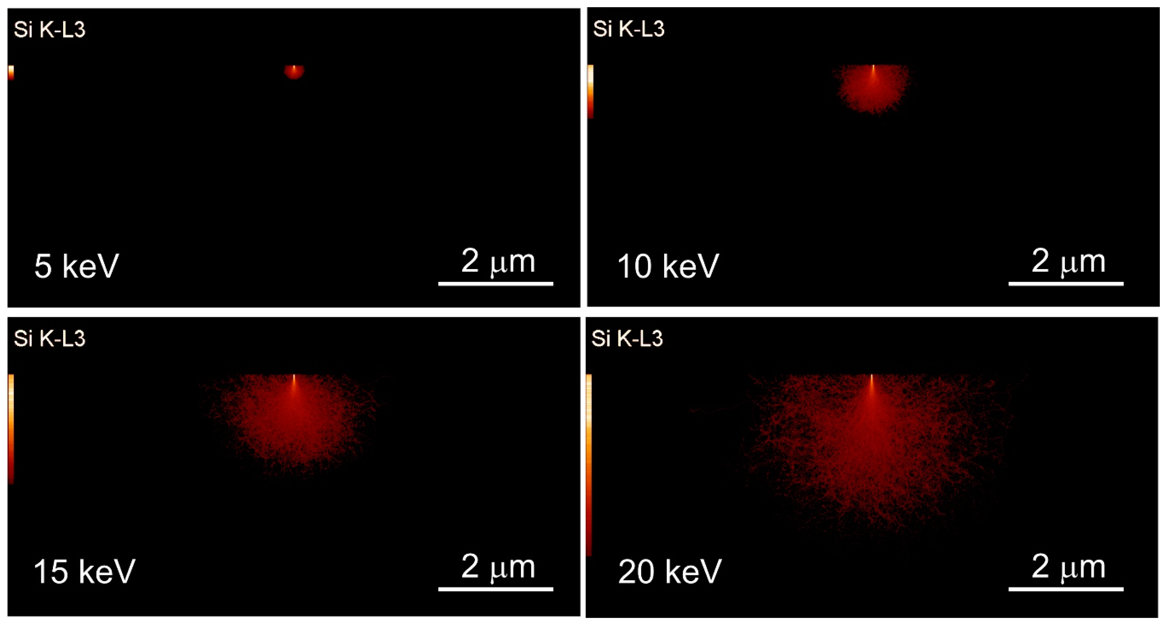
An example of a Monte Carlo simulation of the X-rays generation volumes in a prismatic Egyptian blue fragment of a thickness of 10 μm, obtained with different electron beam energies of 5, 10, 15 and 20 keV is reported in
Figure 1. The figure shows a 2D section of the simulated X-ray generation volume (red area) for the Si line Kα
1 (K-L
3) where an electron beam of 5 nm of probe size (Gaussian width) and zero divergence, is hitting perpendicularly the surface of the specimen in a centred position. The simulation software uses the systematic name (IUPAC) of the X-ray lines, for example in this case Si K-L
3. However, the transitions are more commonly named using the non-systematic or Siegbahn nomenclature, i.e., Si Kα
1; even the majority of the analytical instrument software still employs the latter nomenclature. For the sake of simplicity and clearness, only the upper part of the prismatic sample (dark area) of size 4 μm (height) and 10 μm width is imaged in
Figure 1.
From the simulation, it is clear that the characteristic X-rays of silicon (Si Kα1 X-ray emission line) are generated inside the specimen, and the volume of X-ray generation is higher as the beam energy increases. In addition, these images show that the sites of the internal shell ionisations that give rise to the characteristic X-rays are created in a range of depths well below the surface of the analyzed sample. In the case of silicon ionization, the electron penetration depth as a function of the electron beam energy was 0.25, 0.90, 1.80 and 3.00 μm for 5, 10, 15 and 20 keV, respectively. Therefore, for example, the use of an electron beam energy of 20 keV for the analysis of a 2 μm thick pigment specimen would result in an erroneous estimation of the chemistry of the sample, because its thickness is lower than both the electron penetration and X-ray generation depth.
In the present work, we show the usefulness and practicality of the Monte Carlo simulation to establish a correct SEM-EDS microanalysis strategy. To this aim, we used sample models that consider both chemical composition and fragment geometries (shape and thickness) typically found in the Egyptian blue pigments, from murals in Pompeii. As mentioned above, the two most common shapes (prism and sphere) were simulated with a variable thickness from 100 nm to 10 μm as measured by SEM secondary electron signal. A set of realistic instrumental setups were here used in the simulation, varying the electron beam energy from 5 to 20 keV. The models considered also the mineral pigments mounted on pure carbon or aluminum substrates. However, other beam energies, specimen shapes, thicknesses and supporting substrates can be easily modelled.
3.1. Monte Carlo Simulation of a Prismatic Egyptian Blue Pigment
The Egyptian blue fragments were modelled in a simple prismatic geometry consisting of a 10 × 10 μm square shape in the x, y plane, with a thickness (z-axis) in the range 0.1 to 10 μm, mounted onto a bulk carbon or aluminum substrate, representing typical SEM sample holders and substrates. It is obviously possible to simulate also other types of substrates.
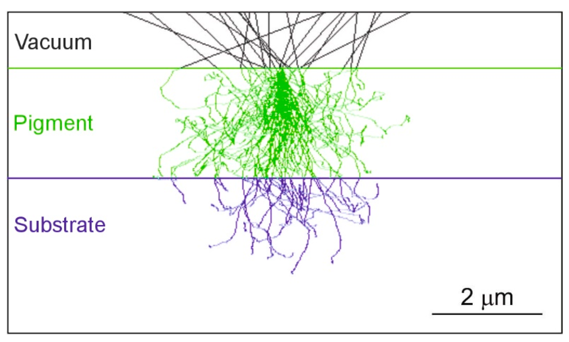
As an example,
Figure 2 shows a middle section of a prismatic Egyptian blue pigment with a thickness of 2 µm, placed onto a carbon substrate, hit by an electron beam of 20 keV energy, probe size of 5 nm and zero divergence, together with the 2D projections of all the electron trajectories. The trajectories of electrons in interaction with the sample are reported in green, those in interaction with the carbon substrate in blue and the backscattered ones escaping out the surface in black (backscattered electrons).
3.1.1. Case of a Prismatic Fragment on a Pure Carbon Substrate
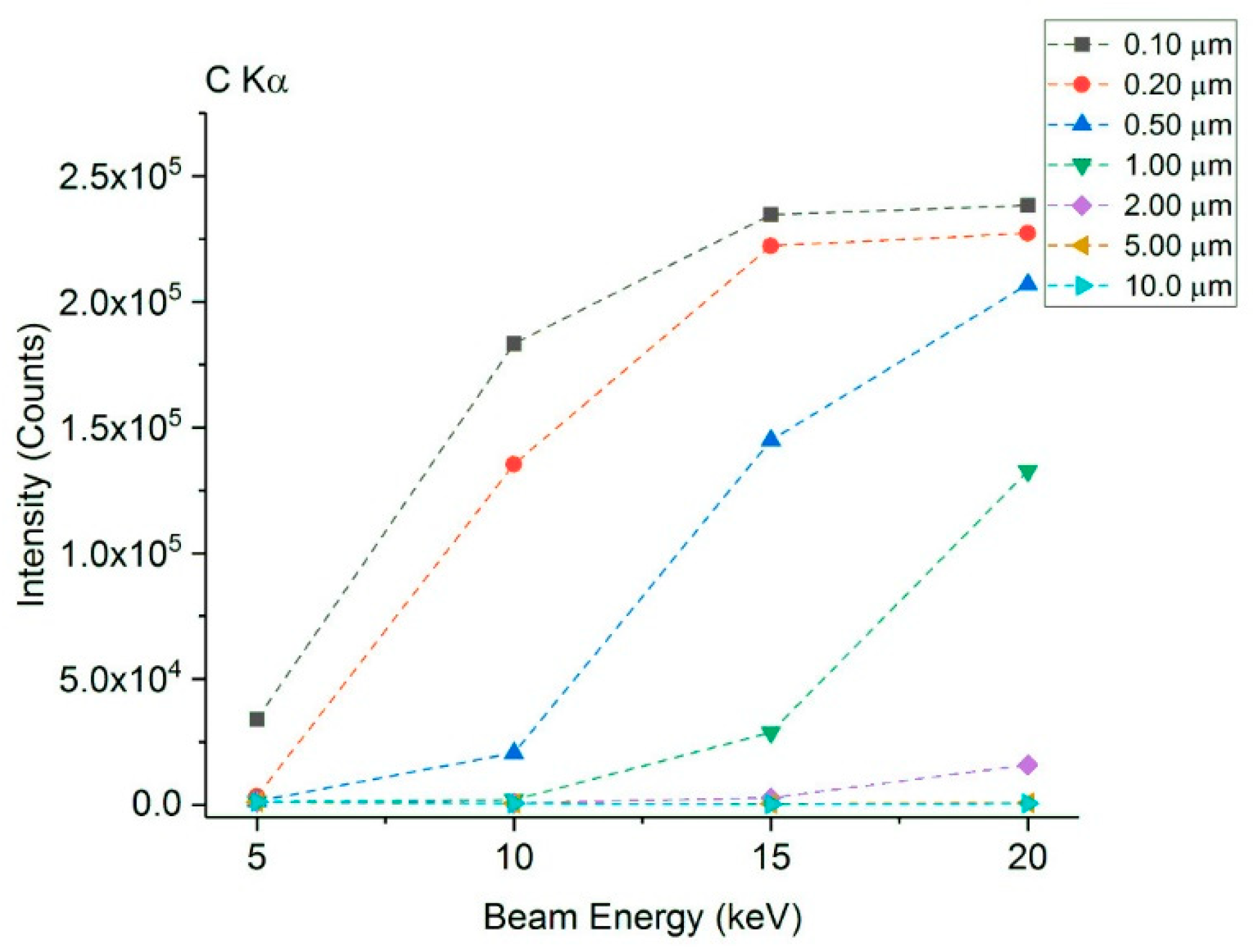
Figure 3 shows the trend of the integrated intensity (counts) of the C Kα X-ray emission line from the pure carbon substrate, obtained by the simulated EDS spectra as a function of the beam energy and the prismatic fragment thickness, according to the scheme of
Figure 2 where the electron probe is focused on the top in the middle position of the pigment fragment. The pigment does not contain carbon and hence the EDS detected signal comes only from the substrate.
For this “artefact” carbon signal, a strong dependence of its intensity of the simulated X-rays versus the pigment thickness was observed. In general, the integrated intensities remain almost constant (no significant visible differences) above a thickness of 5.0 μm at 20 keV, 2.0 μm at 15 keV, 1.0 μm at 10 keV, and between 0.5 μm and 0.2 μm at 5 keV (
Figure 3). For these thickness values, the pigment sample responds as a massive material (i.e., bulk with no significant thickness effect). Therefore, the resulting substrate signal will not significantly affect the microanalysis of the Egyptian blue pigment. Worth to be noted that, for a thickness of the pigment of 0.1 μm, even a value of beam energy as low as 5 keV is not sufficient to avoid some carbon Kα line detection, and other electron microscopy setups and devices should be selected (not reported in the present work).
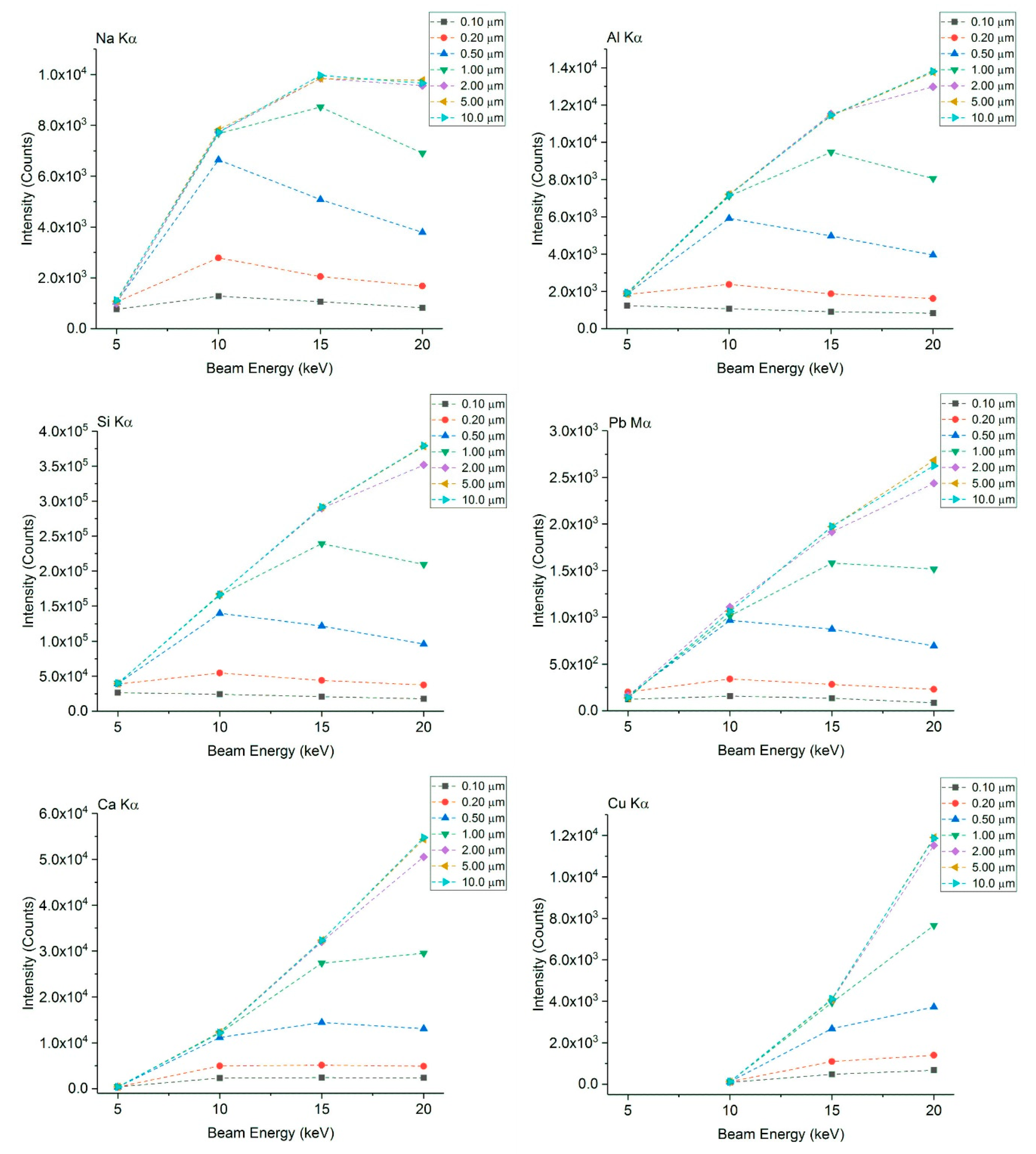
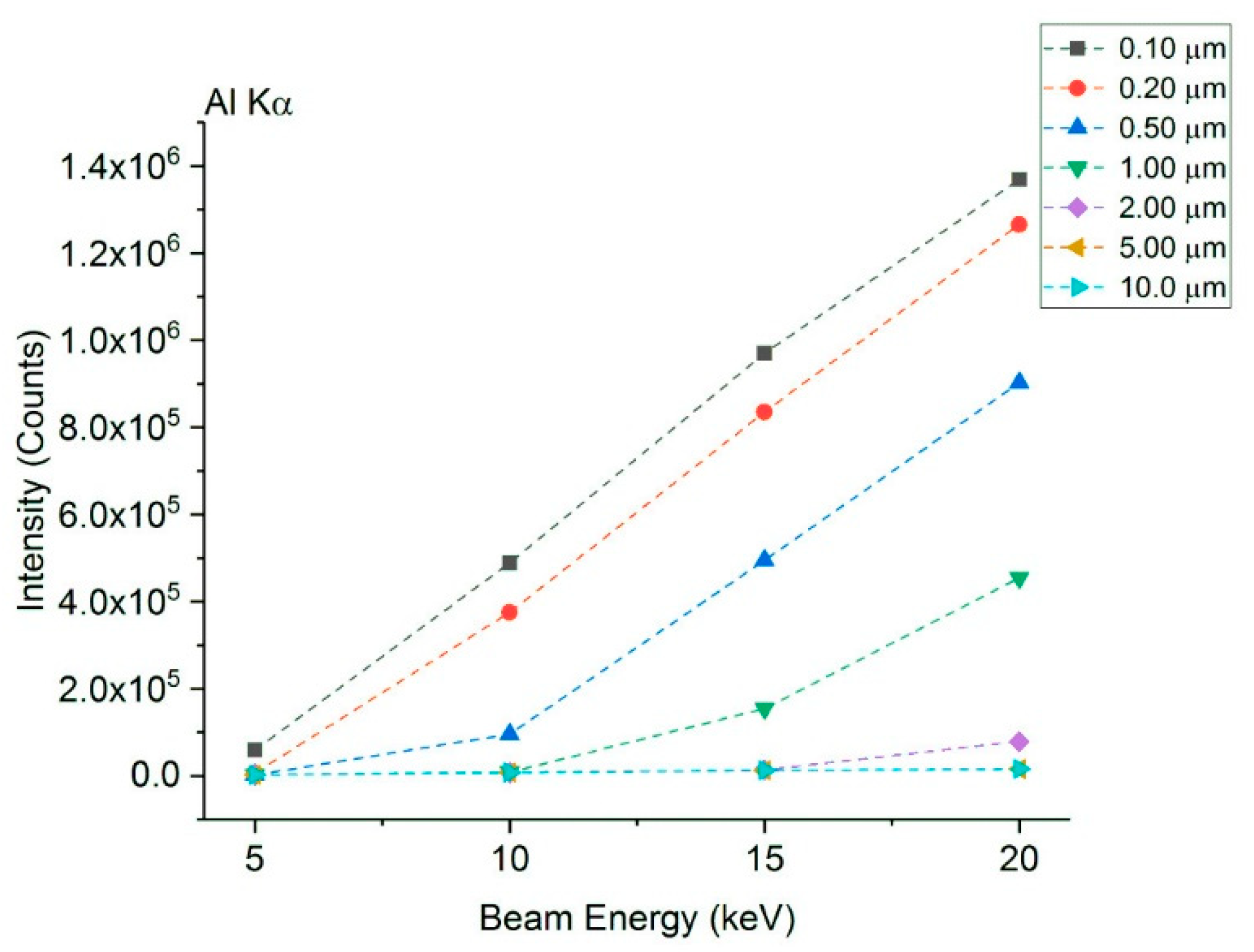
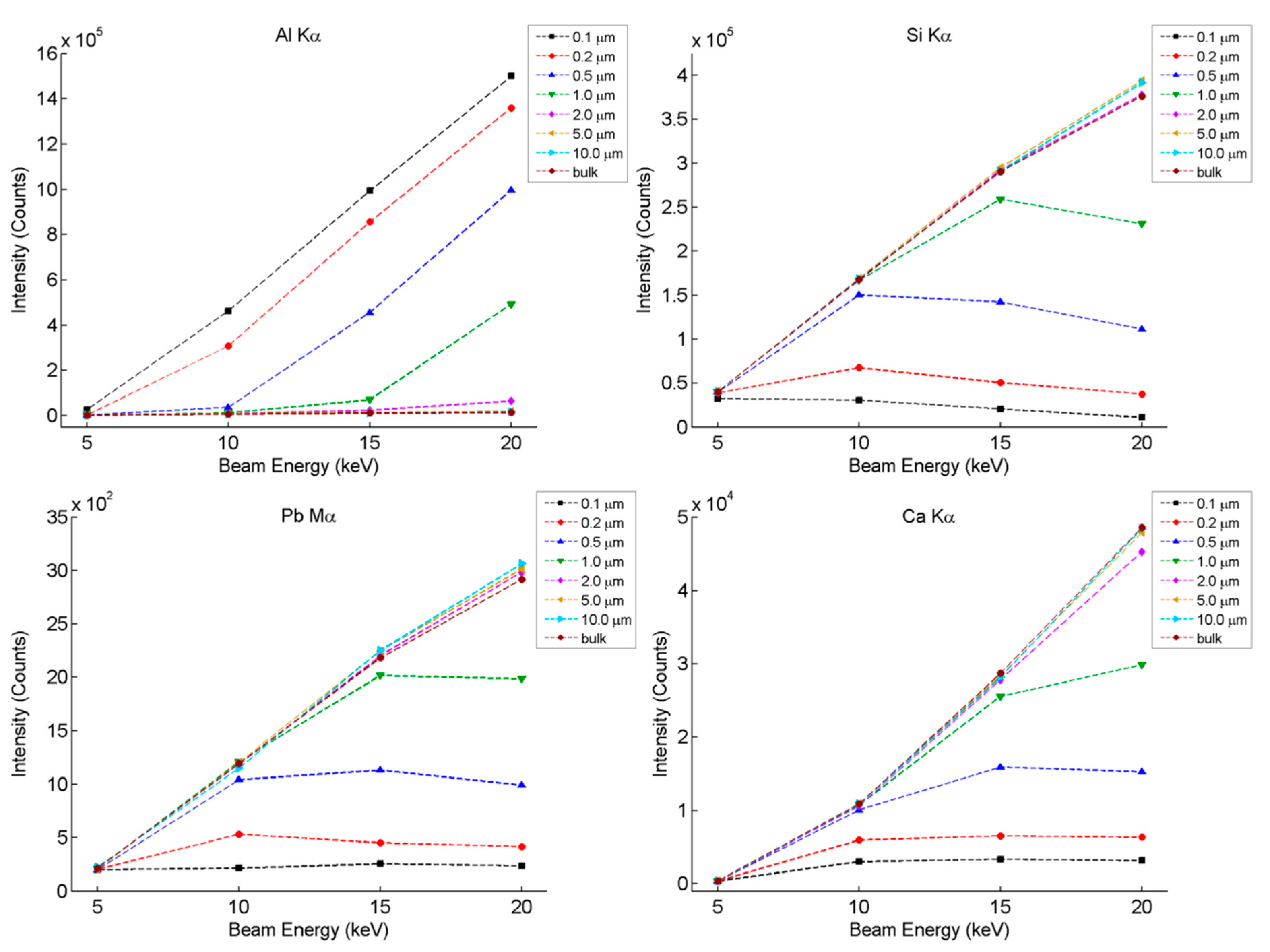
Figure 4 instead reports the net intensities of the main compositional elements of the Egyptian blue pigment (Kα lines for Na, Al, Si, Ca and Cu, and Pb Mα), always calculated for a prismatic sample onto the carbon substrate, in the same experimental conditions (scheme of
Figure 2). The minimum pigment thickness considered as “bulk” and hence independent of the thickness effect, was 5.0 μm at 20 keV, 2.0 μm at 15 keV, 1.0 μm at 10 keV and about 0.5 μm when the beam energy was 5 keV.
Additionally, a reduction in the net intensities of Na, Al, Si and Pb can be observed when the beam energy is increased, which is due to the high absorption effect. For higher beam energy, the interaction volume is larger and the penetration more in-depth. This absorption effect results when an X-ray generated at a specific depth must pass through a volume of sample and can be absorbed without reaching the EDS detector. The other effect involved here is the number of characteristic X-rays produced per incident electron, given by the electron impact X-ray production cross-section (or more specifically, the electron impact ionization cross-section). The more energy an electron possesses, the highest the probability of producing the characteristic X-ray, up to a maximum reached for electron energies of about ~2–3 times the ionization threshold. For higher energies, the X-ray production cross-section will slowly decrease. Additionally, the more energy an electron has, the more total characteristic X-rays it will produce. These two competing processes (creation and absorption) should be taken into account when describing the evolution of the X-ray intensity curve, and explain why there is no reduction in the net intensity for Ca and Cu.
For copper, an electron beam energy of 5 keV is not enough to ionize and produce the characteristic X-ray Kα-line, because its ionization energy is 8.979 keV and another ionization line should be selected for its detection (data not reported).
3.1.2. Case of a Prismatic Fragment on a Pure Aluminum Substrate
When using an aluminum substrate, the minimum pigment thickness for which the sample responds like a bulk material (no significant thickness effect) is 5.0 μm at 20 keV energy; 2.0 μm at 15 keV; 1.0 μm at 10 keV; and between 0.5 μm and 0.2 μm at 5 keV (see
Figure 5). The pigment contains aluminum and hence the substrate may create an additional contribution to the total detected Al.
The effect of the Al substrate on the overestimation of aluminum in Egyptian blue is thus evident and must be considered in a correct analytical SEM-EDS procedure. In fact, the integrated intensity for the Al Kα line can be up to about 88 times higher (at 0.1 μm and 20 keV) than the expected value (the one produced by a bulk pigment, here given by the 10 µm thick geometry), because of the contribution of the aluminum substrate. The selection of an appropriate (medium-low) electron beam energy is, therefore, essential to avoid over-quantification when the fragment has (micro-) nano-metric thicknesses, such as those presented in this study. In addition, the aluminum Kα line peak may change the background profile of other signals near to it (e.g., Si Kα, Na Kα, Mg Kα), providing further difficulties in the correct determination of these elements.
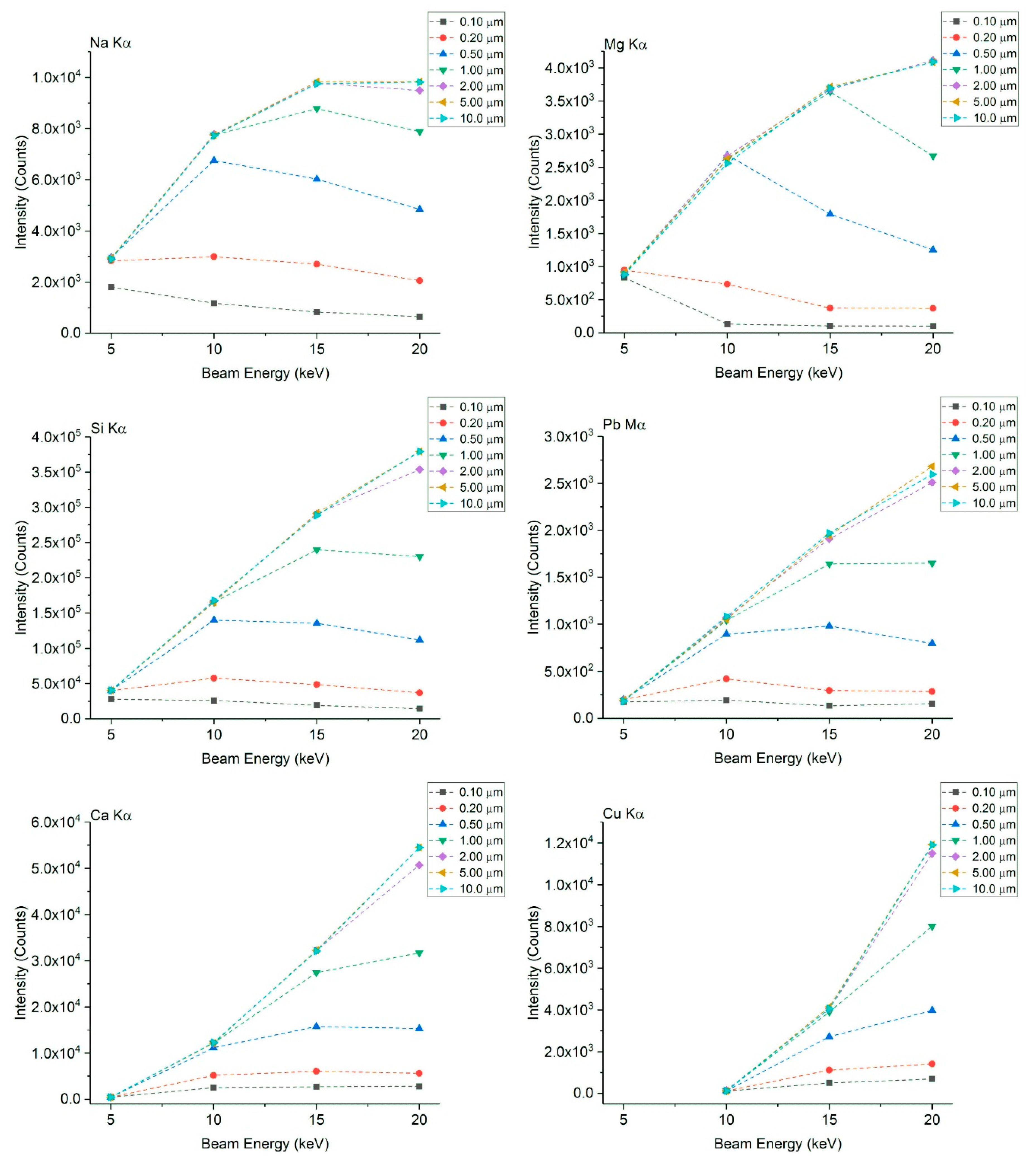
For the rest of the Egyptian blue compositional elements (
Figure 6), the integrated X-ray intensity of each emission lines are constant above 5.0 μm at 20 keV energy; 2.0 μm at 15 keV; 1.0 μm at 10 keV; and between 0.5 and 0.2 μm at 5 keV—the same values as for Al Kα.
Consequently, for the microanalysis of Egyptian blue pigment with prismatic shape, as easily expected, the use of a carbon substrate is recommended against an aluminum one, in order to minimize external contributions from the sample holder, because carbon is in the low energy side and does not affect both the total Al content and the EDS spectrum background. However, when a carbon component has to be studied, such as an organic binder typically found in paintings, for the same reasons depicted for Al, it is suggested to use the SEM secondary electron signal to characterize the shape and size of the binder and Monte Carlo simulations to find out the correct parameters to optimize the overall signal or using different electron microscopy methods (e.g., TEM).
3.2. Monte Carlo Simulation of a Spherical Egyptian Blue Pigment
The Egyptian blue fragments were also modelled in a simple spherical geometry with a radius in the range of 0.1 to 20 μm, mounted on a carbon or aluminum bulk substrate.
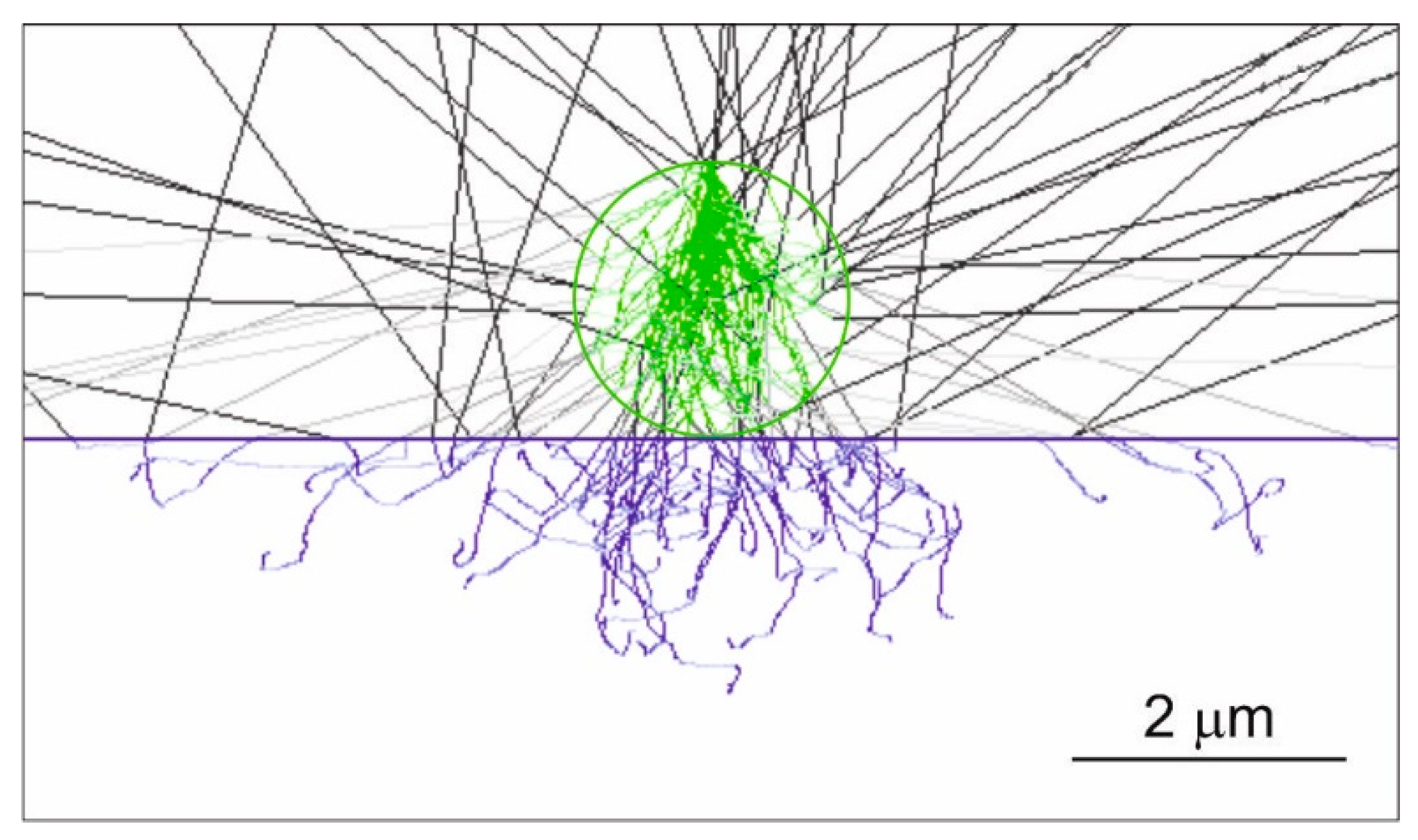
Figure 7 shows a middle section of the simulated spherical Egyptian blue fragment containing the point where an electron probe of 5 nm of diameter, zero divergence, of 20 keV energy hits the topmost surface point, presenting a 2D projection of all the electron trajectories. The figure reports the case of a spherical pigment of a radius of 1 µm (hence the overall maximum thickness of 2 µm) mounted on a carbon substrate. The trajectories of electrons in interaction with the sample are reported in green, those in interaction with the carbon substrate in blue and the backscattered ones escaping out the surface in black (backscattered electrons).
3.2.1. Case of a Spherical Fragment on a Pure Carbon Substrate
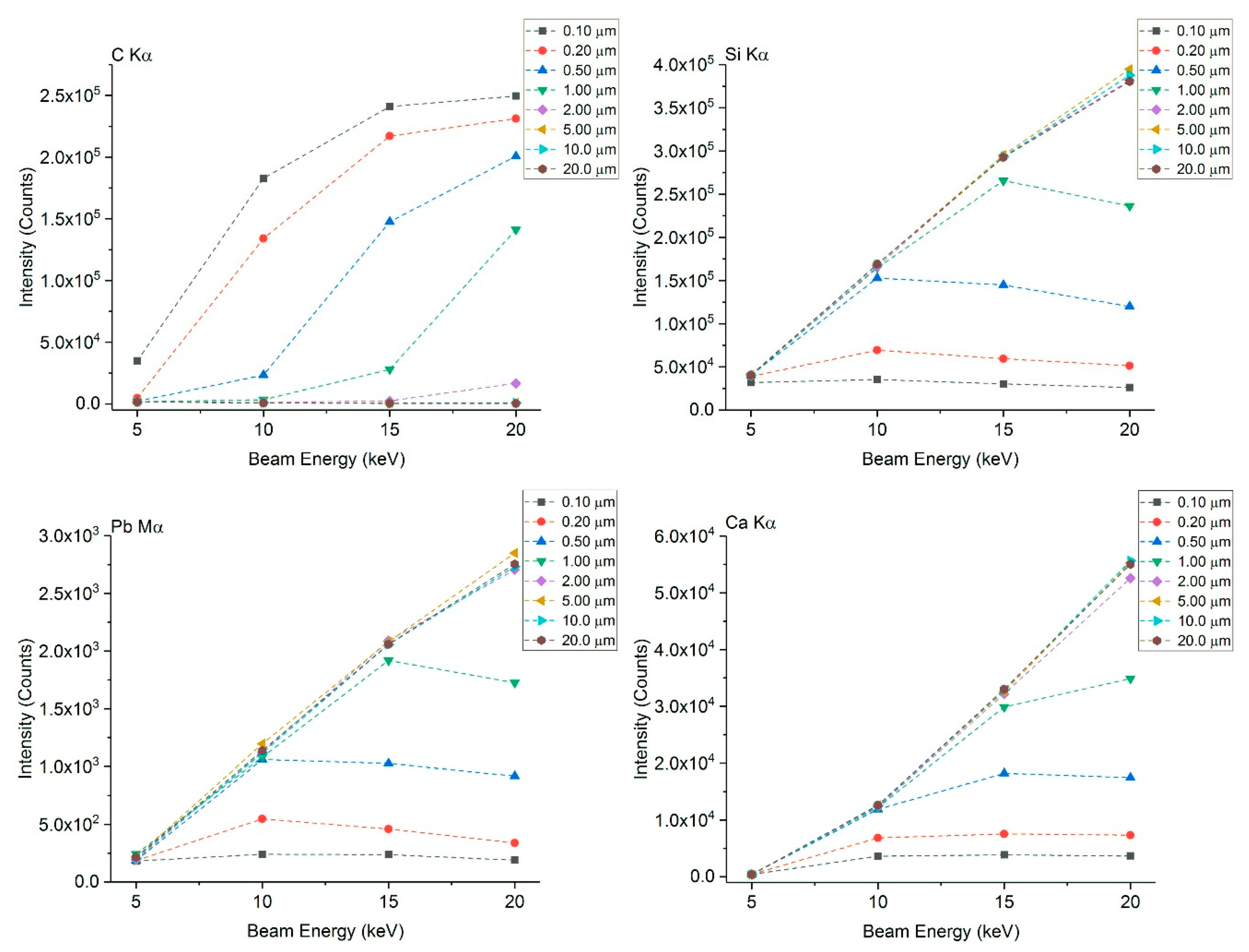
Figure 8 shows the integrated intensities of the EDS spectra for Si Kα and Ca Kα (the two major elements of the Egyptian blue composition), and Pb Mα obtained from the simulated spherical sample (with radius in the range of 0.1 to 20 μm) onto a pure carbon substrate (emitting C Kα). As reported also in
Section 3.1.1., the pigment does not contain carbon and the C Kα EDS-detected signal comes only from the substrate.
No significant contribution of the carbon substrate to the integrated intensity was observed for a beam energy of 20 keV when the pigment radius is equal or greater than 5.0 µm. The same applies at 15 keV, 10 keV and 5 keV, when the pigment radius is at least 2.0 µm, 1.0 µm and 0.2–0.5 µm, respectively.
When the radius of the sample is greater than 5 µm, the spherical pigment behaves almost like a massive sample, independently on the beam energy. The integrated intensities of Ca, Si (Kα) and Pb (Mα) started reducing below a sample radius of about 5.0 µm at 20 keV, 2.0 µm at 15 keV, 1.0 µm at 10 keV and 0.5 µm at 5 keV. The same trend was observed for the other simulated elements (Na, Mg and Cu), here not reported for the sake of brevity.
3.2.2. Case of a Spherical Fragment on a Pure Aluminum Substrate
Figure 9 shows the same Si Kα, Pb Mα and Ca Kα intensities of the Egyptian blue spherical pigment, but mounted onto a pure aluminum sample holder (emitting Al Kα). Note that aluminum is present in both sample and substrate, thus if the electrons interact with the latter, quantification errors will arise, particularly for Al. As for
Section 3.1.2., in this case, the aluminum of the substrate could contribute to the total detected Al, depending on the SEM-EDS measurement conditions.
As also observed for the carbon substrate, no significant contribution of the Al substrate to the integrated intensity was detected for the considered beam energy values, 20 keV, 15 keV, 10 keV and 5 keV, when the pigment radius is equal or greater than 5.0 µm, 2.0 µm, 1.0 µm and 0.2–0.5 µm, respectively. However, by evaluating the trend of the other elements (Si, Pb, Ca), and comparing these X-ray intensity results with X-ray intensities obtained on an actual bulk infinite material, the sample radii resulting as the minimum dimensional thresholds to consider the particle as a bulk (infinite) material were 50 µm, 20 µm, 5 µm and 0.5 µm, when using an electron beam energy of 20 keV, 15 keV, 10 keV and 5 keV, respectively.
It is worth noting that these figures are expressed in terms of particle radius, and it is interesting to see that, compared to the prismatic shape, the spherical sample behaves as a massive sample when its diameter is twice the value of the prismatic shape thickness, at each electron beam energy.
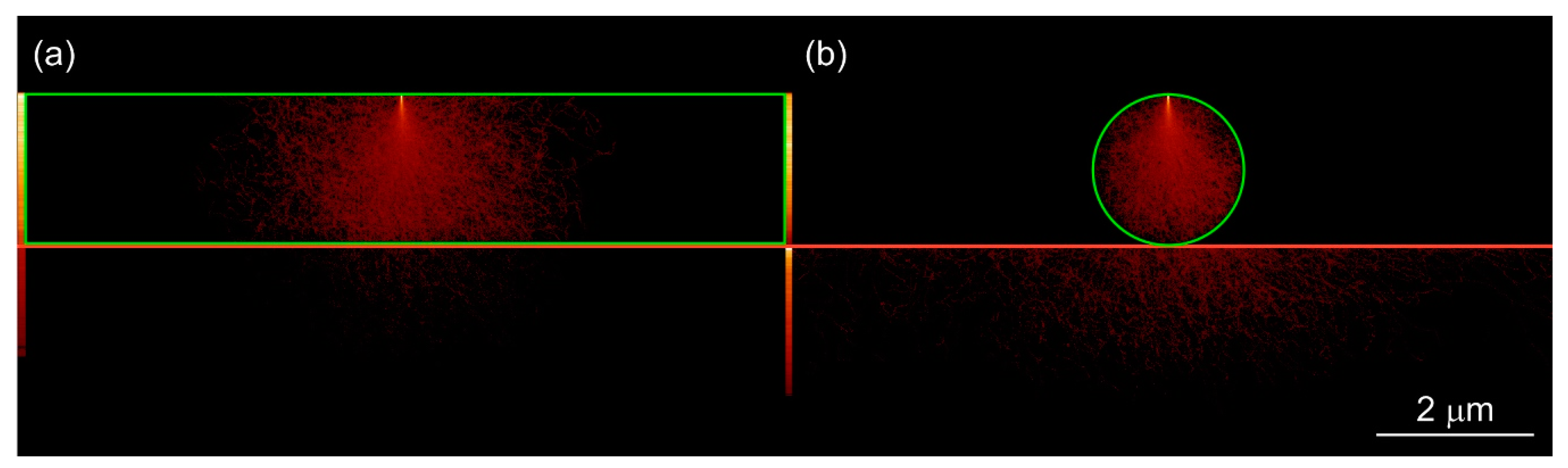
For easier comparison,
Figure 10 reports the simulated Al Kα X-ray generation from a prismatic sample (a) and a spherical one (b), both with a thickness and diameter of 2 μm and mounted onto an aluminum substrate, using a 20 keV electron beam. The probe is focused onto the upper side of the pigment, in the middle position for the prismatic and on the topmost point for the sphere. In each case, the probe size was 5 nm, with zero divergence. The simulation indicates: (i) a lower X-ray emission volume for the spherical sample than the prismatic one, because of the shape of the spherical pigment particle (shape effect); (ii) a greater X-ray generation from the sample holder for the spherical particle case; (iii) a shorter X-ray absorption path in the case of the spherical particle model. These three factors concur at determining an Al Kα X-ray detected intensity for the spherical particle that is about five times that of the prismatic sample, because this element is present in both the pigment and the substrate. Conversely, and as expected, for the other elements (present only in the pigment), the integrated X-ray intensity obtained for the spherical particle is always lower than that of the prismatic one.
In more detail, the elastic scattering of electrons inside the spherical pigment results in a loss of energetic electrons leaving the particle, either contributing to the backscattered signal or entering into the substrate with consequent ionization of its elements. In both cases, the escaped electrons no longer contribute to the generation of X-rays in the sphere. Similar considerations apply in the case of inelastically scattered electrons. In addition, the absorption of X-rays strongly depends on both the materials and the length of the path through the sample. Photon absorption is sensitive to changes in the absorption path length, i.e., the distance between the point where the photon is produced and the detector position, resulting from variations in sample geometry. This effect is more pronounced for low energy photons. In the spherical shape, the length of the photon escape path was shorter compared to that in the prismatic one, which resulted in a reduction in the absorption and a relative increase in the photon intensity. This applies to both the X-ray produced in the particle and those generated in the substrate. Hence, to behave as a bulk similar to the prismatic pigment, the sphere pigment should have its diameter twice the prismatic pigment thickness.
The comparison here presented between the spherical and prismatic pigments is valid at the specific simulated conditions, i.e., with the electron probe focussed in the middle of the sample (see
Figure 10a), far enough from the side edges to avoid lateral interactions. In fact, shape effects could arise even in the prismatic specimen if the electron beam is focussed close to its edge (data not reported).
4. Discussion
A correct determination of the mineralogical and chemical composition at the nano- and micro-scale is nowadays fundamental in microstructural studies of specimens belonging to the Cultural Heritage field, since it helps in guiding the resolution of the nature, genetic and thermodynamic questions concerning the object of study and how to establish restoration and conservation protocols.
In the present work, we used the Egyptian blue mineral pigment as an example and model system to present a microanalytical SEM-EDS approach based on Monte Carlo simulations to investigate the instrumental parameters to obtain optimized results in chemical and mineral analysis. Egyptian blue is identified as cuprorivaite (calcium and copper tetrasilicate) and associated with other trace elements, with prismatic-laminar and spherical forms that predominate with variable thicknesses of few microns.
The results reported in the present work showed that Monte Carlo simulations can be easily used to find out and develop specific analytical SEM-EDS procedures for qualitative and quantitative SEM-EDS microanalysis. It should be remembered that the X-ray intensities here reported were calculated from data simulated in our specific “experimental” conditions (characteristics of our detector and general SEM-EDS set-up) for the Egyptian blue mineral pigment.
When dealing with particles that have (sub-)micrometric sizes and different shapes, there are several physical effects controlled by both the instrumental setups and sample characteristics (geometry and composition) that can severely influence the qualitative and quantitative chemical analysis, often in a non-intuitive way. For instance, even if the spherical particle has a thickness comparable to the prismatic one, its contribution to the EDS spectrum is not easily and directly understood and, even if all the X-ray production volume is contained in the sphere, the traditional quantification method cannot be applied. Indeed, the quantification methods (ZAF and ϕ(ρz) models) assume an absorption correction based on a path calculated for a flat sample. In the case of a sphere, this will always result in an overestimation of the absorption compared to what is measured on a bulk homogeneous standard and will lead to errors in the matrix correction procedure and subsequently in the determined elemental composition. In the case of the spherical particle, geometric effects cannot be neglected except perhaps in the case of extremely large spheres. Monte Carlo simulations should be performed to compare the X-ray intensities emitted from a bulk (infinite) pigment with the intensities emitted from the largest spheres (5 µm at 20 kV, 2 µm at 15 kV, etc). If the emitted X-ray intensities are similar then the traditional quantification method can be applied, otherwise, it should not (or the error should be quantified if possible) and other strategies must be considered. These considerations are in general also valid in the case of more complex shapes.
In addition, the interaction of the electron beam with the substrate affects the analysis and quantification, especially when elements of the substrate are also present in the sample, as in the SEM-EDS analysis of the Egyptian blue pigment mounted on an aluminum stub.
However, in our simulated conditions, when the particle is spherical and even if it has a diameter comparable to the thickness of a prismatic pigment, it is necessary to consider specific warnings in the analytical procedure. The same applies when the sample thickness is equal or below 1 μm. In these cases, it is possible to consider and find out different strategies to obtain a correct chemical quantification.
A solution could be reducing the electron beam energy, with a consequent smaller electron interaction volume (possibly confined within the sample) to have a massive sample (bulk) behavior. However, it could lead to lower the X-ray counts detected and, in some cases, to insufficient energy for the excitation of the characteristic X-ray emission lines of elements (e.g., Cu Kα). To overcome the first issue, it is advisable to increase the acquisition time and/or the probe current, according to the sample stability under the electron beam. The use of a field emission source could be useful. However, it should be noted that increasing the beam current is likely to change the beam diameter, which should be determined according to the method of reference [
25]. For the second issue, as suggested in
Section 3.1.1, one could employ other less energetic characteristic X-ray lines, but taking into account possible peaks overlapping and background related issues.
It must be stressed that the use of a high beam acceleration voltage means that the surroundings of the particle can be excited because of the elastic scattering of electrons and their composing elements may concur in determining the overall EDS spectrum. This could lead to a completely wrong chemical and mineralogical characterization of the particle under investigation.
Thus, a compromise between SEM-EDS operative parameters has to be considered because, generally speaking, X-ray line intensities increase with beam accelerating voltage, but so does electron penetration and scattering, making spatial resolution worse and increasing the absorption suffered by the emerging X-rays.
With Monte Carlo simulations, it is possible to establish “a priori” different combinations of the experimental conditions to optimize the parameters to effective results in chemical and mineral analysis.
As reported and introduced by the authors in previous studies, to show possible chemical microanalytical variations in samples with micrometric and sub-micrometric sizes with respect to a massive sample (bulk), it is suggested to use the net intensity ratios (
k-ratios) [
5,
6]. This quantity
k is defined as the intensity ratio of a specific X-ray line of an element emitted by the pigment particles to the same X-ray line from the same element produced by a reference massive sample (bulk standard of known composition with no thickness and shape effects), in the same SEM-EDS conditions. To this aim, it is necessary to simulate with Monte Carlo a bulk standard typically used in SEM-EDS or electron probe microanalysis (EPMA). The
k-ratios can be calculated as a function of the pigment fragment thicknesses and electron beam energies, in the specific experimental SEM-EDS conditions required.
The experimentalist, when hypothesizing the presence of a particular type of mineral/material, should set optimized SEM-EDS instrumental parameters for the analysis, and determine the effects related to the thickness and shape of the object to avoid or at least to minimize the effects of absorption, thickness, shape, influence of the substrate and the surrounding minerals/materials. Furthermore, Monte Carlo simulation could be indicative of the inadequacy of the SEM-EDS analysis. In that case, particularly for very thin and nano-sized minerals/materials, other electron microscopy methodologies could be more suitable (for instance, TEM/STEM-EDS-EELS, or transmission electron diffraction).
It is also very easy to apply and extend this Monte Carlo method to other subjects and fields of Cultural Heritage and correlated scientific disciplines, where nano/microfeatures, textures, interfaces and particles could be present, for example, in ceramics [
26], clays [
27,
28], glasses, stones, mosaic tesserae [
5,
29,
30], and even metals, alloys and ancient composites (e.g., glass/metals, mineral/metals, organic/minerals).
The Monte Carlo method is a powerful tool to model both electron and X-ray generation and transport, including primary and secondary fluorescence generation, even for complex specimen shapes and SEM chambers and EDS detector geometries and physics.
Interested readers may contact the authors for Monte Carlo simulation and advice for their specific cases.


