Article

Industrial Experiment of Goaf Filling Using the Filling Materials Based on Hemihydrate Phosphogypsum

1
School of Civil and Resources Engineering, University of Science and Technology Beijing, 100083 Beijing, China
2
School of Environment and Safety, Taiyuan University of Science and Technology, 030024 Taiyuan, China
*
Author to whom correspondence should be addressed.
Minerals 2020, 10(4), 324; https://doi.org/10.3390/min10040324
Submission received: 27 February 2020 / Revised: 28 March 2020 / Accepted: 2 April 2020 / Published: 4 April 2020
(This article belongs to the Special Issue Practical Solutions for Underground Mine Backfilling Systems)

Abstract

:
The surface stockpiling of phosphogypsum not only occupies a large amount of land, but also seriously harms the surrounding ecological environment. The preparation of phosphogypsum into filling materials for mine filling can not only maintain the stability of surrounding rock, reduce surface subsidence, enhance the recovery of resources, but it can also completely solve the problem of phosphogypsum stockpiling. Under certain activation conditions, hemihydrate phosphogypsum has a strong cementing property. It is an important way to reduce the filling cost by using hemihydrate phosphogypsum instead of cement as a cementing material. Through laboratory experiments, the filling materials based on hemihydrate phosphogypsum were developed. In order to further verify its feasibility in practical filling engineering, the industrial experiment of goaf filling was carried out in a phosphorus mine. The results show that the filling system was simple, reliable, and easy to operate and manage. The strength of the filling body basically reached the expected strength target of 2.5 MPa in 3 days. The consolidation speed of the filling materials was faster, which is beneficial to the safe underground construction of the mine. The results of the industrial experiment of goaf filling indicate that the filling materials based on hemihydrate phosphogypsum are suitable for mine filling engineering practice, the work amount is small, and the filling cost is low.

1. Introduction

Phosphogypsum is a solid waste discharged during the production of phosphate fertilizer and phosphoric acid [1,2]. For every tonne (t) of phosphoric acid produced, about 4.5~5 t of phosphogypsum is produced [3]. At present, the utilization of phosphogypsum is relatively poor, generally in direct discharge [4,5]. The surface stockpiling of phosphogypsum not only occupies a large amount of land, but also seriously harms the surrounding ecological environment [6,7,8,9,10,11]. Soluble phosphorus and other potentially harmful elements in phosphogypsum can be leached by rainwater to form acidic wastewater, causing the serious pollution of soil and the water system [12,13,14,15,16,17,18]. Therefore, the comprehensive utilization of phosphogypsum has become an important issue for the sustainable development of the phosphorus chemical industry and environmental protection [19,20,21,22,23,24].
China is rich in phosphate resources, with large-scale mining occurring in recent years, and large areas of goaf have been formed in many areas. Goaf is prone to cause disasters such as overlying rock caving, surface subsidence, and goaf waterlogging, which seriously affect the safety of mine production. The preparation of phosphogypsum into filling materials for mine filling can not only maintain the stability of surrounding rocks, reduce the surface subsidence, and enhance the recovery of resources [25,26,27,28], but it can also completely solve the problem of phosphogypsum stockpiling and ensure the sustainable development of mines [29,30,31,32,33].
By-product phosphogypsum can be divided into dihydrate phosphogypsum and hemihydrate phosphogypsum according to different production technology of wet process phosphoric acid. Dihydrate phosphogypsum can only be used as aggregate in mine filling [34,35,36]. This method has the problems of high cement consumption and high filling cost. At the same time, because the particles of dihydrate phosphogypsum are very small, it has the characteristics of degradation in water, a small permeability coefficient, and has a delayed coagulation effect on cement, which is not conducive to the rapid dehydration and hardening of filling materials. Therefore, it is not an ideal filling aggregate. Adding yellow phosphorus slag and other cementing materials could reduce the cost of cement, but it increases the complexity of the process and reduces the usage amount of phosphogypsum [37].
A chemical company adopts the hemihydrate production technology of wet process phosphoric acid, the by-product of which is mainly hemihydrate phosphogypsum. The experimental results show that under certain excitation conditions, hemihydrate phosphogypsum has strong cementitious activity and can be used to prepare new filling cementing materials [38,39,40]. The filling materials based on hemihydrate phosphogypsum can achieve high strength just using cheap waste. Therefore, it has unique advantages in technology, economics, environmental protection, and security. It is an important way to reduce the filling cost of mines by using hemihydrate phosphogypsum instead of cement as cementing material [41,42].
Through laboratory experiments, a new type of filling materials based on hemihydrate phosphogypsum with a controllable setting time, high early strength, a low bleeding ratio, and good fluidity was developed [42,43]. In order to further verify its feasibility in practical filling engineering, the industrial experiment of goaf filling was carried out in a phosphorus mine. The purpose of this study is to find out the suitable ratio and filling technology of the filling materials based on hemihydrate phosphogypsum through industrial experiments, to solve the problems existing in mine filling applications, and to provide technical support for large-scale promotion and application in the future. The technical parameters of the filling process using the filling materials based on hemihydrate phosphogypsum in the large-scale filling experiment were determined. The consolidation speed, strength, and durability of the filling body were studied. The preparation and transportation technology of the filling materials were optimized, and the pipeline transportation performance of the filling materials based on hemihydrate phosphogypsum was investigated.

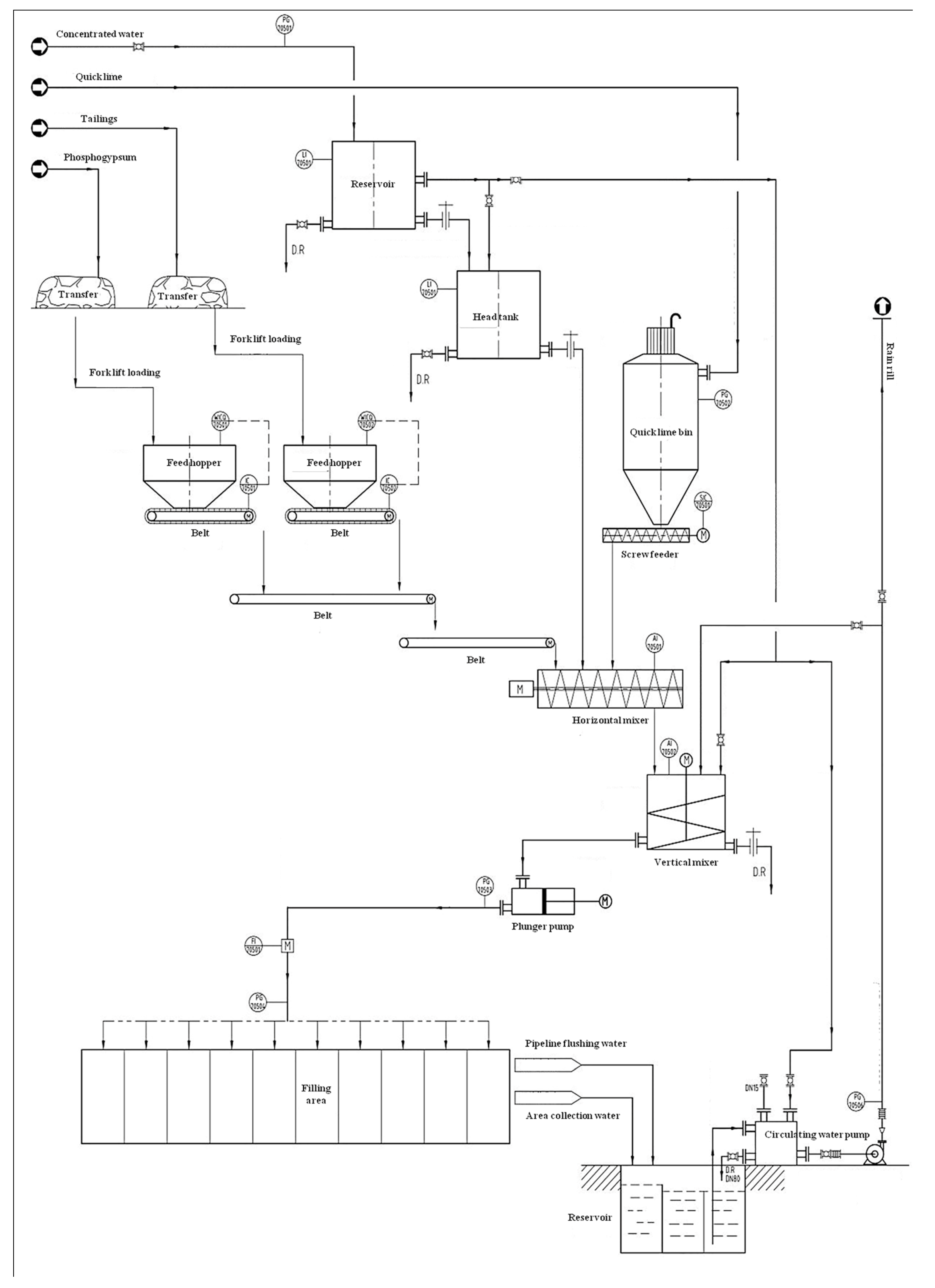
2. Filling System and Process Flow

A good filling system should first meet the basic needs of production, and then have reasonable pipeline transportation parameters and stowing gradient, so as to achieve the safety, economy, and efficiency of the filling task. The filling system of the filling materials based on hemihydrate phosphogypsum was designed, which is suitable for the technical form of preparing filling slurry from dry materials. The designed filling system used the process of pumping for large stowing gradient and gravity flow for small stowing gradient. According to the capacity of the filling system, the intermittent stir method for slurry preparation was selected. The filling process flow is shown in Figure 1.

2.1. Filling Material Ratio

The filling materials included hemihydrate phosphogypsum, tailings, quicklime, and mine underground water. According to the strength requirement of the filling body and the recommended ratio of laboratory experiments, the ratio of tailings-hemihydrate phosphogypsum filling material was determined as 31% water, 25.6% tailings, 42.7% hemihydrate phosphogypsum, and 0.7% quicklime. That is, the dosage of each material in each ton of tailings-hemihydrate phosphogypsum filling material was, respectively: 310 kg/t of water, 256 kg/t of tailings, 427 kg/t of hemihydrate phosphogypsum, and 7 kg/t of quicklime. Since the specific gravity of the filling slurry was 1.8 g/cm3, it can be calculated that 568 kg/m3 of water, 461 kg/m3 of tailings, 769 kg/m3 of hemihydrate phosphogypsum, and 11.5 kg/m3 of quicklime were required for the filling materials. The ratio of dihydrate-hemihydrate phosphogypsum filling material was determined as: 1.5% quicklime, 40% dihydrate phosphogypsum, and 69% concentration. That is, the dosage of each material in each ton of dihydrate-hemihydrate phosphogypsum filling material was, respectively: 310 kg/t of water, 195 kg/t of dihydrate phosphogypsum, 487.5 kg/t of hemihydrate phosphogypsum, and 7.5 kg/t of quicklime. Since the specific gravity of the filling slurry was 1.79 g/cm3, it can be calculated that 555 kg/m3 of water, 349 kg/m3 of dihydrate phosphogypsum, 873 kg/m3 of hemihydrate phosphogypsum, and 13.5 kg/m3 of quicklime were required for the filling materials.

2.2. Metering and Loading

After the preparation of hemihydrate phosphogypsum and tailings in the mine, they were transferred to the intermediate storage yard by transfer vehicles. The storage capacity of the phosphogypsum yard and the tailings yard was about 250 and 100 m3, respectively, which were the maximum usage amount for one day for them. The quicklime was transported to the quicklime stock bin by the tank lorry for temporary storage. The storage capacity was 20 m3. The required industrial water was from the clear water of the production pipe network in the factory.
Hemihydrate phosphogypsum was transferred from the yard by the scraper to the feed hopper, which was used for temporary storage. Then, it was fed to the measuring hopper by the belt at the bottom of the stock bin. After the weight loss metering, the materials were loaded to the mixer via belt. In order to avoid large agglomerates entering the pipeline transportation system, the hemihydrate phosphogypsum should be smashed. After the materials were smashed, it was transferred to the feed hopper through the belt. The upper part of the feed hopper was provided with a 10-mm sieve, and the remaining large agglomerates were returned to smash. Then, the smashed hemihydrate phosphogypsum was entered the feeding system again.
Because hemihydrate phosphogypsum contained a certain amount of free water, its migration velocity in the stock bin was slow and there was a risk of feed difficulty. The stock bin shall be installed with the wall vibrator to ensure the smooth feeding of hemihydrate phosphogypsum.
The filling station was equipped with two 200 t auxiliary material bins, and the auxiliary materials of one auxiliary material bin were released for storing quicklime. Quicklime was transported from the auxiliary material bin by the screw feeder to the mixer. Because quicklime is can easily absorb water, the sealing of the auxiliary material bin should be carefully checked before industrial filling experiment.
A head tank was installed, and the height of the water in the tank was controlled to measure the amount of water. The water was supplied by the reservoir and sent to the water measuring hopper in the stir building through the water pump. After that, the water was discharged to the batch mixer. In the process of industrial filling, the water volume should be strictly controlled to ensure that the slurry concentration is within the design range.
Hemihydrate phosphogypsum and tailings were, respectively, provided with transfer stock bins with a volume of about 10 m3 to facilitate forklift loading. A scraper chain conveyor was set up under the transfer stock bin. The scraper chain conveyor and the transfer stock bin were installed on a support, and the weight loss weighing of support was carried out. The stop of the scraper chain conveyor was interlocked with the weight loss weighing sensor, so as to achieve the purpose of stable feeding and accurate measurement.

2.3. Preparation and Transportation of Slurry

The existence of a certain amount of fine particles less than 15 μm in tailings can improve the transport stability of filling slurry through the role of water retention and fluidity improvement. There was still some agglomeration phenomenon in the smashed tailings, and the tailings and hemihydrate phosphogypsum were separately fed when the slurry was prepared. After the tailings were smashed, they were firstly transported to the mixer. At the same time, some water was added for pre-stirring for 30 s so that the tailings particles could be fully dispersed in the water to ensure the stability and homogeneity of the paste slurry. The contact time between the tailings and water and hemihydrate phosphogypsum was increased to ensure uniform mixing of the filling materials.
The stirring preparation system was intermittent operation, and a JS3000 double horizontal shaft forced mixer (Fontai, Zhengzhou, China) was selected as the equipment. Each preparation quantity was 3 m3, the stirring shaft rotation rate was 26 r/min, and the complete cycle time was 5 min, in which the feeding time was 2 min, the stirring time was 2 min, and the unloading time was 1 min. A slurry transfer tank was provided below the mixer to reserve the paste slurry. The qualified paste slurry prepared by the double horizontal shaft forced mixer was put into the slurry transfer tank to stabilize the feed quantity of the delivery pump. The paste slurry was then transported to the filling zones at a steady speed through the delivery pump.
When the filling capacity under the condition of gravity flow failed to meet the flow requirement of the experiment design, it is necessary to increase the pipe diameter and add the plunger pump to solve the problem. After the filling slurry was evenly stirred, it was fed to the buffering tank and then transported to the filling zones by gravity flow or pumping. In order to avoid the settling and segregation of the filling slurry in the buffering tank, it is necessary to set up a stirring device inside the buffering tank. A flashboard was set up at the outlet to control the discharge flow.
For filling zones where the stowing gradient can realize slurry gravity flow and meet the flow requirements, the gravity flow mode was adopted. The pumping system was only used in filling zones where the critical non-flow stowing gradient was exceeded and those where the flow was small due to the overlarge stowing gradient. When the pumping method was adopted, the qualified paste prepared by the double horizontal shaft forced mixer was firstly put into the slurry transfer tank, and then the paste slurry was transported to the filling zones at a stable speed by paste delivery pump. After the filling was completed, the pumping pipeline was rinsed with cleaned water to prevent pipeline blockage caused by the settling and consolidating of the residual slurry in the pipeline. The washing water was not allowed to enter the filling zones to avoid affecting the consolidation and hardening of the filling body. Slurry transportation adopted a 0.12-m inner diameter filling pipeline. The slurry conveying equipment adopted the plunger pump, with a conveying capacity of 60~100 m3/h and a pumping pressure range of 5~10 MPa. In the process of industrial filling, the pump pressure of plunger pump should take as small a value as possible so as to avoid overlarge residual head causing wear to the filling pipeline.

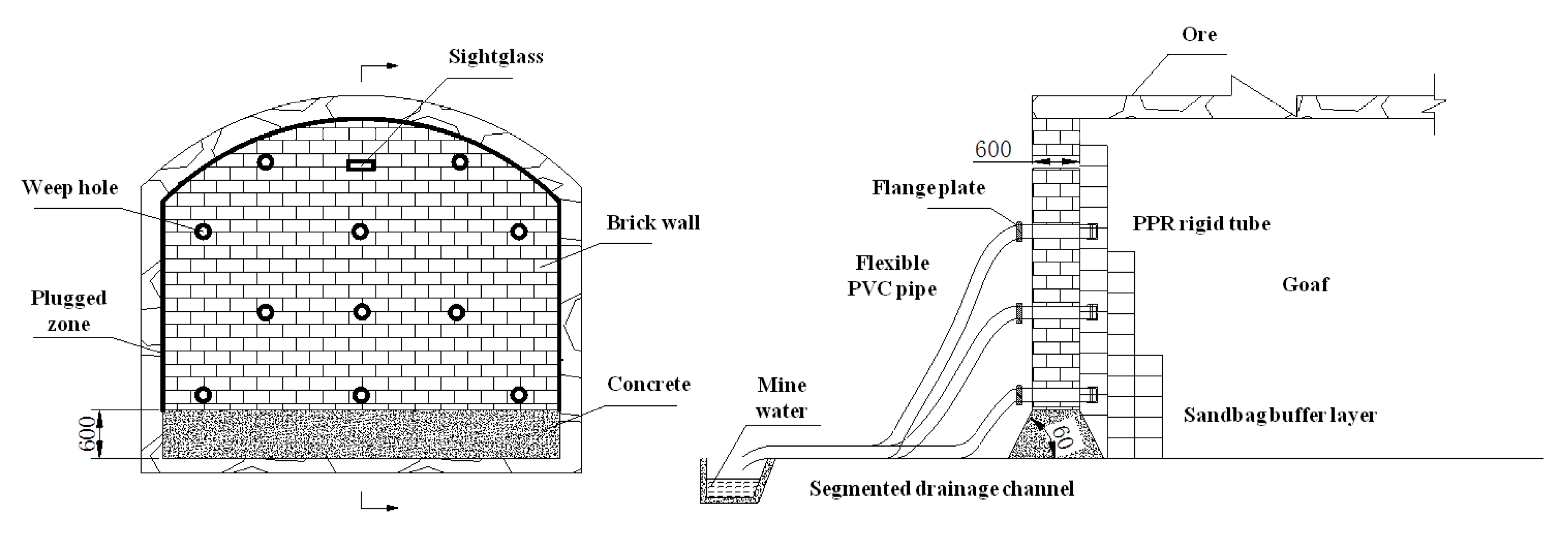
2.4. Retaining Wall Construction and Goaf Filling

Filling retaining wall construction is one of the main tasks before goaf filling. In the case of non-solidification, with the increase in filling height, the lateral pressure to the retaining wall increases sharply. The safety of the retaining wall is particularly important for underground safe production. Before the goaf filling, there was a brick isolation wall between the roadway and the goaf in the filling zone to prevent people from straying into it. The isolation retaining wall was about 1.2 m in high and 20 cm thick, with drainage holes arranged inside to serve as the discharge fort of leached water in the goaf. The fill’s retaining wall was modified from the existing isolation retaining wall. It was transformed by first increasing the thickness of the retaining wall to 600 mm. Then, according to the conditions, three sandbag-buffering layers were set on the side of the retaining wall near the goaf, and the heights from inside to outside were 1.0, 2.0 and 3.0 m, respectively. The filling retaining wall is shown in Figure 2.
When the wall was building, the footing of the wall was cleaned firstly, then the high-grade concrete mortar was used to build the 600-mm-wide foundation. After that, the mortar was used to fix the stagger upper and lower layers of the bricks to build wall. The wall was 600 mm thick, and then 50 mm of mortar was sprayed. After 1 d, the filling can be carried out. In order to prevent the slurry leakage accident, the plugging between the filling retaining wall and the goaf should be strengthened. The goaf must be plugged with scaffolding, a sheet steel form, and plastic cloth, and the gaps can be plugged with cotton yarn (for personnel observation). The flange was used to connect the PVC hose according to the conditions to drain the filling effluent to the subsection drainage channel to strengthen the filling effluent collection management.
At the beginning of the goaf filling, filling work should be done in stages. In the early stage of goaf filling, the filling height of the slurry in the goaf should be controlled to be less than 1.5 m each time to prevent the collapse of retaining wall caused by overlarge filling slurry pressure. When the filling slurry exceeded 980 m of retaining wall open wiring 1~2 m, the filling process was stopped until the filling slurry completed solidification. At this point, the filling slurry at the bottom of the goaf had been consolidated, and the filling body had little lateral pressure on the retaining wall, which can accelerate the filling speed and continuously fill.
During the filling process, a person was assigned to observe the position and consolidation situation of filling slurry so as to timely adjust the ratio of filling slurry according to the requirements of filling design. Meanwhile, the start and stop of filling were controlled to reduce the probability of a filling slurry leakage accident. If a slurry leakage was found, the filling work was stopped in time, and the plugging treatment was adopted. When the filling liquid level reached the designed filling elevation, the surface filling preparation station was notified to end the filling operation.

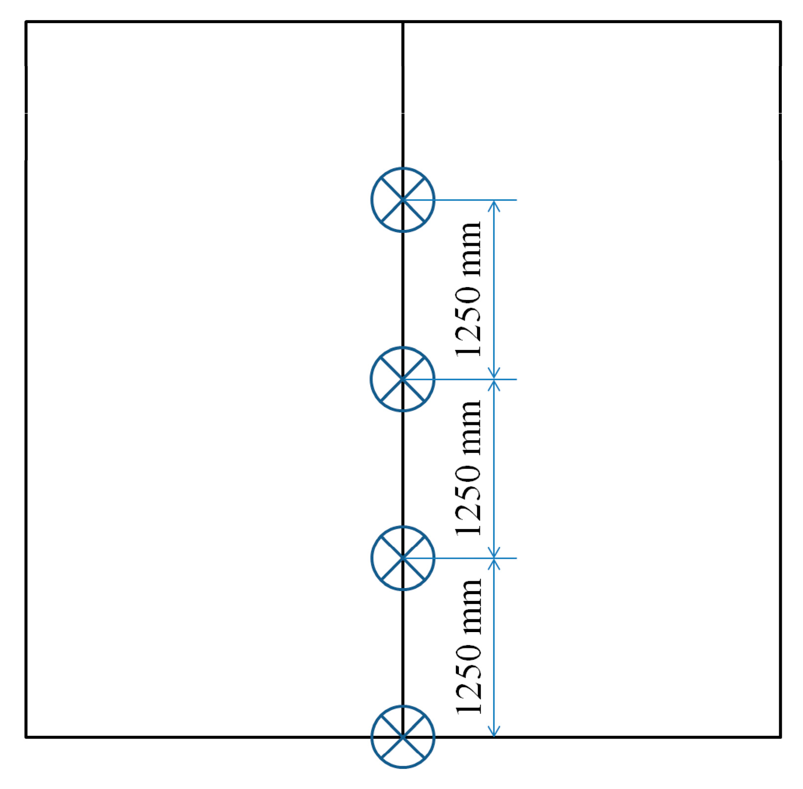
3. Monitoring of Filling Process

3.1. Monitoring of Filling Slurry Preparation

The filling slurry was taken from the material distributing pipeline at the bottom of the buffering tank every 2 h, and its density was measured by a measuring bucket with a certain volume. The slurry density is calculated as follows:
ρ = G V
where ρ is the filling slurry density, G is the filling slurry mass in the measuring bucket, and V is the measuring bucket volume.
Slump and diffusance were used to characterize slurry fluidity. The filling slurry was taken from the material distributing pipeline at the bottom of the buffering tank every 2 h to measure slump and diffusance. Specific determination methods refer to the standard test method of performance on ordinary fresh concrete [44]. After the slump was determined, 3 diameters of the slurry in different directions were taken as the diffusance, accurate to 0.5 cm.
The filling slurry was taken from the material distributing pipeline at the bottom of the buffering tank every 2 h, and the slurry mass M0 was weighed. Then, anhydrous ethanol was added in a 1:1 ratio to stop the hydration of hemihydrate phosphogypsum. Finally, the filling slurry was put into the oven, where it was baked at 60 °C for 24 h. After drying, the mass was M. The actual concentration of filling slurry c is determined as follows:
c = M M 0
The amount of bleeding of filling slurry is directly related to the range of influence of filling process on the surrounding water environment and the regional water environmental capacity evaluation. The amount of bleeding was characterized by the bleeding rate. The filling slurry was taken from the material distributing pipeline at the bottom of the buffering tank three times and was poured into three measuring cylinders of the same type. The slurry was stirred evenly before being poured into the measuring cylinder, and the slurry mass was record as M0. After standing the measuring cylinder for 10 min, the upper clarified water was poured out. Then, at an interval of 1 min, the clarified water was absorbed from the upper part of the measuring cylinder through the dropper until the bleeding stopped. The final mass of slurry was weighed as M1. During the experiment, the slurry bleeding rate was monitored every 2 h. The calculation method of the bleeding rate b is as follows:
b = M 0 M 1 M 0

3.2. Monitoring of Filling Slurry Transportation

Slurry flow monitoring was accomplished by a flowmeter set on the conveying pipeline. After the installation of the flowmeter, the manufacturer first conducted the zero calibration of the meter. Then, the object calibration was carried out. The object calibration method was that, within a certain period of time, the slurry was fed into the agitation vat, the slurry height in the agitation vat was measured, the actual flow was calculated, and then it was compared and corrected with the display data of the flowmeter. In the industrial experiment, the instantaneous and cumulative flow values of filling slurry were recorded every hour.
To monitor the pressure inside the pipeline, a total of two pressure gauges were set, which were, respectively, placed at the outlet of the plunger pump pipeline and the outlet of the goaf filling pipeline. The distance between them was the total length of the filling pipeline.

3.3. Monitoring of Filling Body Strength

In the industrial experiment, the strength of the filling body was tested by means of slurry molding, worksite cutting ring sampling test and finally borehole sampling test.

3.3.1. Test of Slurry Molding

The filling slurry was released from the material distributing pipeline at the bottom of the buffering tank and was then poured to become test blocks in the laboratory for standard curing. The compressive strength of the filling body was measured for 3 d, 7 d and 28 d. The test blocks were made by a 7.07 × 7.07 × 7.07 cm mold. Without changing the filling ratio, three triplet test blocks were poured every 4 h, and a test block was poured once after the filling ratio was changed for 10 min.

3.3.2. Worksite Cutting Ring Sampling Test

In the filling body test area, the filling body samples were obtained by a geotechnical cutting ring. The compressive strength of the filling body was measured for 3 d, 7 d and 28 d under indoor standard curing conditions.

3.3.3. Final Borehole Sampling Test

After the completion of the filling experiment, survey agencies with relevant qualifications were invited to obtain the samples of the filling body by drilling and measuring the strength of the filling body at 3 d, 7 d, 28 d, 60 d, 120 d, 240 d and 360 d, respectively. The long-term strength and durability of the filling body were investigated.

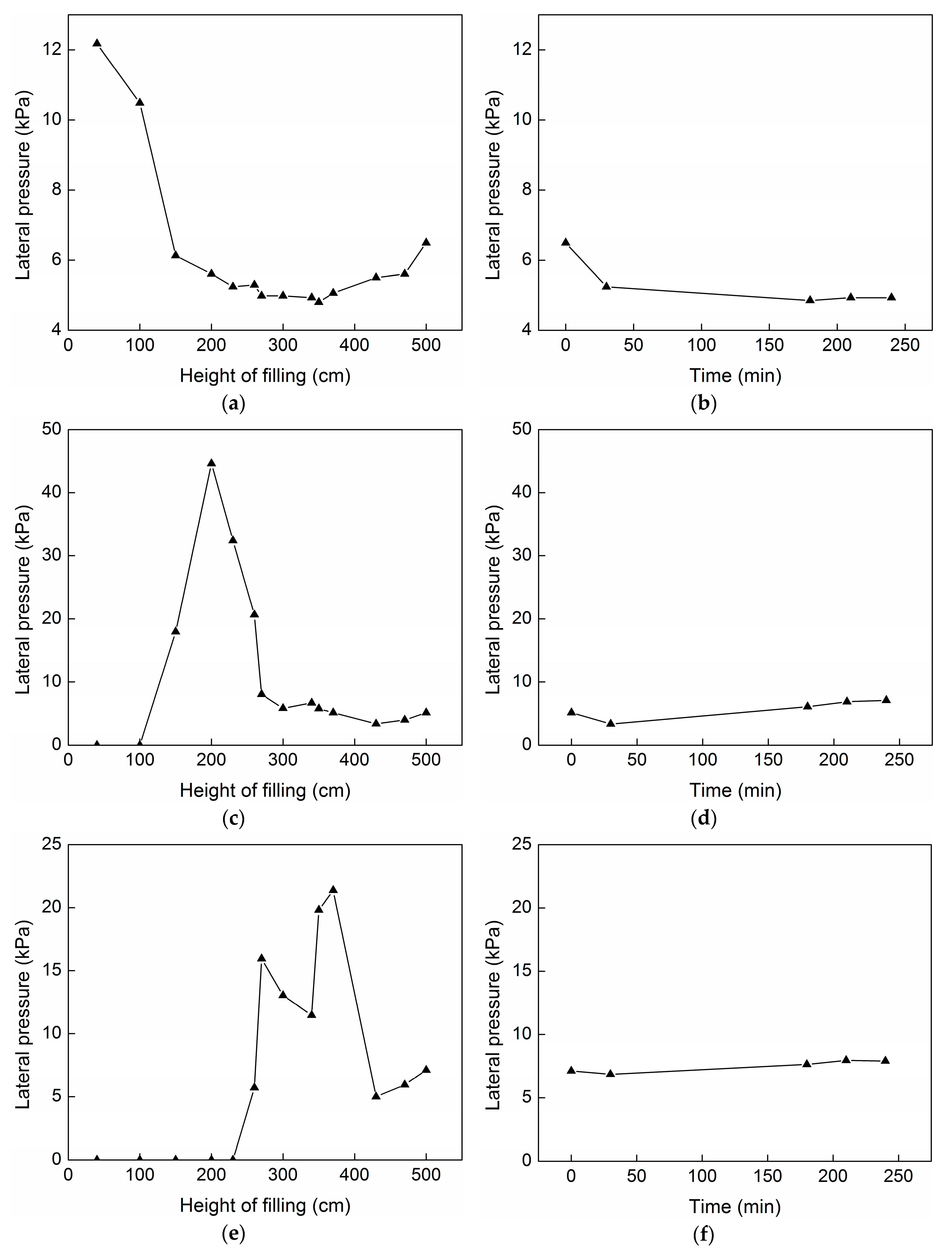
3.4. Monitoring of Filling Body Consolidation

Four pressure boxes were arranged between the filling body and the geotechnical filtering cloth to monitor the lateral pressure of the filling body on the retaining wall and analyze the consolidation of the filling body. The arrangement heights of the pressure boxes were 0, 1.25, 2.5 and 3.75 m, respectively. The pressure boxes were numbered 1, 2, 3 and 4. The pressure box arrangement is shown in Figure 3.
With the continuous entry of filling slurry, the pressure value of each pressure box was monitored successively. A reader was used to read the initial value f0 of each pressure box. With the extension of filling time, the reading fi of different pressure boxes and the filling height H were recorded at certain intervals. The monitoring frequency of the pressure boxes was adjusted according to the consolidation speed of the filling body, and the initial monitoring frequency was 0.5 h/time. If the pressure boxes data drops rapidly, the monitoring frequency remained 0.5 h/time. If the pressure box data decrease slowly, the monitoring frequency should be reduced to 1.0 h/time. The conversion relationship between the pressure box reading and filling pressure P is shown in the following formula:
P = K ( f i 2 f 0 2 )
K is a constant.

4. Results and Discussion

4.1. Preparation of Filling Slurry

In the filling process, due to the unstable quality of hemihydrate phosphogypsum and the difficulty in grasping the water content in hemihydrate phosphogypsum, dihydrate phosphogypsum, and tailings, it is necessary to monitor the material composition and the prepared filling slurry at random to ensure that the slurry quality meets the requirements. The monitoring results are shown in Table 1 and Table 2. It can be seen from those two tables that, during the filling process in each filling zone, slurry concentration at each stage saw little change, with the maximum difference of slurry concentration being 4.05% and the minimum difference being 0.90%. This is because hemihydrate phosphogypsum and tailings contain some free water, and the free water content fluctuates with the change of production process, resulting in a change in slurry concentration.
During the filling process, the samples from the outlet were washed with alcohol and sent to the laboratory for testing the actual slurry concentration. By comparing the actual slurry concentration with the designed slurry concentration, it was found that there is little difference between the two concentrations, which ensured the stability of slurry concentration in the filling process.

4.2. Pipeline Pressure and Pipeline Flow

During the filling process, pressure changes at both ends of the pipeline were monitored in real time through pressure sensors located at both ends of the pipeline. The monitoring results are shown in Table 3 and Table 4.
The industrial experiment used intermittent filling, in which the filling materials in the pipeline would have a brief stagnation. Due to the fast consolidation of the filling materials, the yield stress would increase sharply, resulting in large pressure losses. In subsequent industrial applications, continuous filling will be used, and the on-way resistance will be reduced. In the industrial experiment, in order to reduce costs, the filling capacity and pipeline size were small. In subsequent industrial applications, the appropriate pipeline size will be determined according to the filling capacity and flow.

4.3. Filling Slurry Preparation Quality

During the filling process of each filling zone, the specific gravity, slump, diffusance, and bleeding rate of the filling slurry were measured by sampling from the outlet every 1 h. In order to ensure the evaluation quality of the filling body, the filling body strength test was carried out by the survey agencies.
The test results are shown in Table 5 and Table 6. It can be seen that the strength of the filling body formed by filling slurry basically reached the expected strength target of 2.5 MPa in 3 d. However, the strength results and other data in the test fluctuated, and some of the data were slightly lower than the design value, mainly because of the following reasons. The unstable process control in the workshop, coupled with the opening and stopping due to the planned overhaul, led to the fluctuation of organic matter, and free P and F contents in the hemihydrate phosphogypsum. The suspension of equipments sometimes resulted in a long storage time for hemihydrate phosphogypsum, which resulted in a higher content of crystal water and decreased the strength of the filling body formed. The filling experiment was in winter and the temperature was low, resulting in a low initial temperature when the hydration of the hemihydrate phosphogypsum. In order to improve the filling efficiency, the stirring time was reduced. So, the mixing uniformity of the filling slurry was worse than that of the filling slurry stirred for 10 min in the laboratory test, thus partially reducing the strength of the filling body. The long-term strength of the filling body formed by tailings-hemihydrate phosphogypsum filling material and dihydrate-hemihydrate phosphogypsum filling material at 60 d, 120 d, 240 d and 360 d was 4.3, 4.6, 4.5 and 4.4 MPa and 4.1, 4.2, 4.0 and 4.2 MPa, respectively. The long-term strength of the filling body was stable.

4.4. Consolidation of Filling Body

During the filling process and after the filling completion, the data of the pressure boxes on the retaining wall were read every 30 min until the data did not change much. The monitoring results are shown in Figure 4. It can be seen that, during the filling process, the lateral pressure of the filling body to the retaining wall and the internal pressure of the filling body gradually increased. After increasing to the peak, the pressure gradually decreased and eventually stabilized around a pressure value. This is because as the filling height increased during the filling process, the filling body transferred the pressure to the retaining wall through dead weight, so the lateral pressure increased accordingly. After a period of filling, the lower filling body was basically consolidated, and the dead weight pressure of the upper filling body cannot be transferred to the lower layer, so the pressure of the pressure boxes did not change much. After 2 h of filling, the lateral pressure of No. 1 pressure boxes stabilized at about 5.28 kPa. Within 2–2.5 h, the lateral pressure of No. 2 pressure boxes gradually increased to the peak, and the lateral pressure gradually decreased within 2.5–4 h of the filling and finally stabilized around 5.6 kPa. The pressure variation trend of No. 3 and No. 4 pressure boxes was the same as that of No. 1 and No. 2 pressure boxes. The final lateral pressures were 6.91 and 115.2 kPa, respectively. It indicated that the filling body had been basically consolidated at this time.
It can be seen that in the filling process, the consolidation speed of the filling materials based on hemihydrate phosphogypsum was faster. Although the lateral pressure of the filling body to the retaining wall and the internal pressure of the filling body gradually increased during the filling process, the filling slurry no longer formed hydrostatic pressure on the filling retaining wall after the fast consolidation of the filling body. After a short period of time, the early filling body in the lower layer was basically consolidated. It is conducive to safe underground construction. However, there is a problem that the displaced air cannot be discharged, resulting the large wall pressures at the final filling stage. Therefore, we consider using the filter to drain and exhaust in time to replace the previous drainage method in the following industrial applications.

5. Technological and Economic Advantages

Based on the summary of the industrial filling process, it was found that, compared with the traditional cement-tailings filling materials, the filling materials based on hemihydrate phosphogypsum had the advantages of high early strength, a short curing time, a low bleeding rate, and a low filling cost. The slurry concentration of the intermittent preparation with dry materials was easier to control, and the formed filling slurry was better homogeneous, without settling and segregation.
The filling materials based on hemihydrate phosphogypsum can greatly reduce the filling cost. Table 7 shows the comparison of unit filling cost between the hemihydrate phosphogypsum filling process and the cement-tailings filling process. It can be seen that, due to the high content of cement in the cement-tailings filling material, the average cost of the cement-tailings filling material per cubic meter is about 100 China Yuan (CNY). However, only a small amount of quicklime is required to be purchased for the tailings-hemihydrate phosphogypsum filling material, and only 11.5 kg of quicklime is required for each cubic meter filling material. The local quicklime cost is about 350~360 CNY/t, so the material cost per cubic meter is only about 5~6 CNY. Compared with the traditional cement-tailings filling process, the filling cost can be reduced by more than 90% when the tailings-hemihydrate phosphogypsum filling material is used.
It can be seen from Table 7 that the proportion of wastes in solid materials of the filling materials based on hemihydrate phosphogypsum account for more than 98%. Therefore, the filling materials based on hemihydrate phosphogypsum can dispose of solid wastes safely and efficiently, alleviate environmental hazards, and bring good environmental benefits. In addition, the early strength of the filling materials is high and the curing time is small, which can shorten the production cycle and accelerate the recovery of ore. With the improvement of the recovery rate, it can extend the length of service of the mine on the premise of achieving the same amount of resources and show good social benefits.
The filling body formed by the filling materials based on hemihydrate phosphogypsum all meets the requirements of class I industrial solid wastes. Its 3 days uniaxial compressive strength is all up to 2.5 MPa, and the long-term strength is stable. The permeability coefficient is less than 2.31×10⁻⁶ cm/s, less than 1000 times of the hemihydrate phosphogypsum slag yard. There was no external drainage in the filling process.
Therefore, the filling materials based on hemihydrate phosphogypsum are not only suitable for the efficient comprehensive utilization of phosphogypsum in mine filling but can also solve the safety problem of phosphogypsum and tailings stockpiling and eliminate the hidden danger of phosphogypsum to environmental pollution.

6. Conclusions

The filling system, process flow, application effect, and economic benefit related to the filling materials based on hemihydrate phosphogypsum were analyzed by an industrial filling experiment.
Compared with hydraulic sand filling, common tailings cementing filling and high-concentration cementing filling, the filling system of the filling materials based on hemihydrate phosphogypsum was simple, reliable, applicable to various topographic conditions, and has a lower operation cost and management difficulty. All the experimental raw materials were filtered, dehydrated, and stored by dry method, with low moisture content and good stability, so the concentration in the slurry preparation process was easier to control than that of the thickening device. The materials were measured by the weight loss weighing method, with small errors and high precision, ensuring the quality of the filling body. Two-stage stirring (double shaft intense stirring and vertical stirring) was used. The filling materials were mixed evenly, the stirring quality was good.
The strength of the filling body formed by the filling materials based on hemihydrate phosphogypsum in the filling industrial experiment basically reached the expected strength target of 2.5 MPa in 3 days, and the strength results were basically consistent with the results of the indoor ratio optimization test. In the filling process, the consolidation speed of filling materials based on hemihydrate phosphogypsum was faster. Although the lateral pressure and internal pressure of the filling body on the retaining wall gradually increased during the filling process, it no longer formed hydrostatic pressure on the filling retaining wall after the fast consolidation of the filling body. After a short period of time, the early filling body in the lower layer was basically consolidated, which is conducive to safe underground construction.
The results of the filling industrial experiment indicate that the filling materials based on hemihydrate phosphogypsum are suitable for mine filling engineering practice, the work amount is small, and the filling cost is low. The filling materials based on hemihydrate phosphogypsum can effectively govern the underground goaf, solve the problem of phosphogypsum surface stockpiling, and truly realize the sustainable development of the phosphorus mines.

Author Contributions

Methodology, W.L.; formal analysis, K.R. and W.L.; writing—original draft preparation, K.R.; writing—review and editing, K.R. and H.L.; supervision, W.L.; project administration, W.L.; funding acquisition, H.L. All authors have read and agreed to the published version of the manuscript.

Funding

This research was funded by Shanxi Provincial Key Research and Development Project (International Cooperation), China [grant numbers 201803D421095] and Shanxi Provincial Applied Basic Research Program, China [grant numbers 201901D111250].

Acknowledgments

The authors would like to thank the field technicians for their great help.

Conflicts of Interest

The authors declare no conflict of interest.

References

  1. Tian, T.; Yan, Y.; Hu, Z.H.; Xu, Y.Y.; Chen, Y.P.; Shi, J. Utilization of original phosphogypsum for the preparation of foam concrete. Constr. Build. Mater. 2016, 115, 143–152. [Google Scholar] [CrossRef]
  2. Lopez, F.A.; Gazquez, M.; Alguacil, F.J.; Bolivar, J.P.; Garcia-Diaz, I.; Lopez-Coto, I. Microencapsulation of phosphogypsum into a sulfur polymer matrix: Physico-chemical and radiological characterization. J. Hazard. Mater. 2011, 192, 234–245. [Google Scholar] [CrossRef] [PubMed] [Green Version]
  3. Tayibi, H.; Choura, M.; Lopez, F.A.; Alguacil, F.J.; Lopez-Delgado, A. Environmental impact and management of phosphogypsum. J. Environ. Manag. 2009, 90, 2377–2386. [Google Scholar] [CrossRef] [PubMed] [Green Version]
  4. Cuadri, A.A.; Navarro, F.J.; Garcia-Morales, M.; Bolivar, J.P. Valorization of phosphogypsum waste as asphaltic bitumen modifier. J. Hazard. Mater. 2014, 279, 11–16. [Google Scholar] [CrossRef] [Green Version]
  5. Abril, J.M.; Garcia-Tenorio, R.; Perianez, R.; Enamorado, S.M.; Andreu, L.; Delgado, A. Occupational dosimetric assessment (inhalation pathway) from the application of phosphogypsum in agriculture in South West Spain. J. Environ. Radioact. 2009, 100, 29–34. [Google Scholar] [CrossRef]
  6. Yang, F.; Li, G.X.; Shi, H.; Wang, Y.M. Effects of phosphogypsum and superphosphate on compost maturity and gaseous emissions during kitchen waste composting. Waste Manag. 2015, 36, 70–76. [Google Scholar] [CrossRef]
  7. Rosales, J.; Perez, S.M.; Cabrera, M.; Gazquez, M.J.; Bolivar, J.P.; de Brito, J.; Agrela, F. Treated phosphogypsum as an alternative set regulator and mineral addition in cement production. J. Clean Prod. 2020, 244, 118752. [Google Scholar] [CrossRef]
  8. Torres-Sanchez, R.; Sanchez-Rodas, D.; de la Campa, A.M.S.; de la Rosa, J.D. Long term geochemical variation of brines derived from a major phosphogypsum pond of SW Europe. J. Environ. Manag. 2020, 254, 109832. [Google Scholar] [CrossRef]
  9. Lieberman, R.N.; Izquierdo, M.; Cordoba, P.; Palmerola, N.M.; Querol, X.; de la Campa, A.M.S.; Font, O.; Cohen, H.; Knop, Y.; Torres-Sanchez, R.; et al. The geochemical evolution of brines from phosphogypsum deposits in Huelva (SW Spain) and its environmental implications. Sci. Total Environ. 2020, 700, 134444. [Google Scholar] [CrossRef]
  10. Attallah, M.F.; Metwally, S.S.; Moussa, S.I.; Soliman, M.A. Environmental impact assessment of phosphate fertilizers and phosphogypsum waste: Elemental and radiological effects. Microchem. J. 2019, 146, 789–797. [Google Scholar] [CrossRef]
  11. Perez-Moreno, S.M.; Gazquez, M.J.; Perez-Lopez, R.; Vioque, I.; Bolivar, J.P. Assessment of natural radionuclides mobility in a phosphogypsum disposal area. Chemosphere 2018, 211, 775–783. [Google Scholar] [CrossRef]
  12. Huang, Y.B.; Qian, J.S.; Lu, L.C.; Zhang, W.S.; Wang, S.D.; Wang, W.L.; Cheng, X. Phosphogypsum as a component of calcium sulfoaluminate cement: Hazardous elements immobilization, radioactivity and performances. J. Clean Prod. 2020, 248, 119287. [Google Scholar] [CrossRef]
  13. Al-Hwaiti, M.; Ibrahim, K.A.; Harrara, M. Removal of heavy metals from waste phosphogypsum materials using polyethylene glycol and polyvinyl alcohol polymers. Arab. J. Chem. 2019, 12, 3141–3150. [Google Scholar] [CrossRef] [Green Version]
  14. Li, B.; Shu, J.C.; Yang, L.; Tao, C.Y.; Chen, M.J.; Liu, Z.H.; Liu, R.L. An innovative method for simultaneous stabilization/solidification of PO43 and F from phosphogypsum using phosphorus ore flotation tailings. J. Clean Prod. 2019, 235, 308–316. [Google Scholar] [CrossRef]
  15. Gasser, M.S.; Ismail, Z.H.; Abu Elgoud, E.M.; Hai, F.A.; Ali, O.I.; Aly, H.F. Process for lanthanides-Y leaching from phosphogypsum fertilizers using weak acids. J. Hazard. Mater. 2019, 378, 120762. [Google Scholar] [CrossRef]
  16. Shu, J.C.; Chen, M.J.; Wu, H.P.; Li, B.B.; Wang, B.; Li, B.; Liu, R.L.; Liu, Z.H. An innovative method for synergistic stabilization/solidification of Mn2+, NH4+-N, PO43– and F in electrolytic manganese residue and phosphogypsum. J. Hazard. Mater. 2019, 376, 212–222. [Google Scholar] [CrossRef]
  17. Vasconez-Maza, M.D.; Martinez-Segura, M.A.; Bueso, M.C.; Faz, A.; Garcia-Nieto, M.C.; Gabarron, M.; Acosta, J.A. Predicting spatial distribution of heavy metals in an abandoned phosphogypsum pond combining geochemistry, electrical resistivity tomography and statistical methods. J. Hazard. Mater. 2019, 374, 392–400. [Google Scholar] [CrossRef]
  18. Jalali, J.; Gaudin, P.; Capiaux, H.; Ammar, E.; Lebeau, T. Fate and transport of metal trace elements from phosphogypsum piles in Tunisia and their impact on soil bacteria and wild plants. Ecotox. Environ. Safe. 2019, 174, 12–25. [Google Scholar] [CrossRef]
  19. Liu, D.S.; Wang, C.Q.; Mei, X.D.; Zhang, C. An effective treatment method for phosphogypsum. Environ. Sci. Pollut. Res. 2019, 26, 30533–30539. [Google Scholar] [CrossRef]
  20. Grabas, K.; Pawelczyk, A.; Strek, W.; Szeleg, E.; Strek, S. Study on the Properties of Waste Apatite Phosphogypsum as a Raw Material of Prospective Applications. Waste Biomass Valorization 2019, 10, 3143–3155. [Google Scholar] [CrossRef] [Green Version]
  21. Liu, S.H.; Wang, L.; Yu, B.Y. Effect of modified phosphogypsum on the hydration properties of the phosphogypsum-based supersulfated cement. Constr. Build. Mater. 2019, 214, 9–16. [Google Scholar] [CrossRef]
  22. Romero-Hermida, M.I.; Borrero-Lopez, A.M.; Alejandre, F.J.; Flores-Ales, V.; Santos, A.; Franco, J.M.; Esquivias, L. Phosphogypsum waste lime as a promising substitute of commercial limes: A rheological approach. Cem. Concr. Compos. 2019, 95, 205–216. [Google Scholar] [CrossRef]
  23. Huang, Y.B.; Qian, J.S.; Kang, X.J.; Yu, J.C.; Fan, Y.R.; Dang, Y.D.; Zhang, W.S.; Wang, S.D. Belite-calcium sulfoaluminate cement prepared with phosphogypsum: Influence of P2O5 and F on the clinker formation and cement performances. Constr. Build. Mater. 2019, 203, 432–442. [Google Scholar] [CrossRef]
  24. Ennaciri, Y.; Bettach, M. Procedure to convert phosphogypsum waste into valuable products. Mater. Manuf. Process. 2018, 33, 1727–1733. [Google Scholar] [CrossRef]
  25. Tariq, A.; Yanful, E.K. A review of binders used in cemented paste tailings for underground and surface disposal practices. J. Environ. Manag. 2013, 131, 138–149. [Google Scholar] [CrossRef]
  26. Khaldoun, A.; Ouadif, L.; Baba, K.; Bahi, L. Valorization of mining waste and tailings through paste backfilling solution, Imiter operation, Morocco. Int. J. Miner. Sci. Technol. 2016, 26, 511–516. [Google Scholar] [CrossRef]
  27. Ouattara, D.; Yahia, A.; Mbonimpa, M.; Belem, T. Effects of superplasticizer on rheological properties of cemented paste backfills. Int. J. Miner. Process. 2017, 161, 28–40. [Google Scholar] [CrossRef]
  28. Benzaazoua, M.; Fall, M.; Belem, T. A contribution to understanding the hardening process of cemented pastefill. Miner. Eng. 2004, 17, 141–152. [Google Scholar] [CrossRef]
  29. Min, C.D.; Li, X.B.; He, S.Y.; Zhou, S.T.; Zhou, Y.N.; Yang, S.; Shi, Y. Effect of mixing time on the properties of phosphogypsum-based cemented backfill. Constr. Build. Mater. 2019, 210, 564–573. [Google Scholar] [CrossRef]
  30. Li, X.B.; Du, J.; Gao, L.; He, S.Y.; Gan, L.; Sun, C.; Shi, Y. Immobilization of phosphogypsum for cemented paste backfill and its environmental effect. J. Clean Prod. 2017, 156, 137–146. [Google Scholar] [CrossRef]
  31. Chen, Q.S.; Zhang, Q.L.; Qi, C.C.; Fourie, A.; Xiao, C.C. Recycling phosphogypsum and construction demolition waste for cemented paste backfill and its environmental impact. J. Clean Prod. 2018, 186, 418–429. [Google Scholar] [CrossRef]
  32. Chen, Q.S.; Zhang, Q.L.; Fourie, A.; Xin, C. Utilization of phosphogypsum and phosphate tailings for cemented paste backfill. J. Environ. Manag. 2017, 201, 19–27. [Google Scholar] [CrossRef]
  33. Li, X.B.; Zhou, Y.N.; Zhu, Q.Q.; Zhou, S.T.; Min, C.D.; Shi, Y. Slurry Preparation Effects on the Cemented Phosphogypsum Backfill through an Orthogonal Experiment. Minerals 2019, 9, 31. [Google Scholar] [CrossRef] [Green Version]
  34. Li, X.B.; Zhou, S.T.; Zhou, Y.N.; Min, C.D.; Cao, Z.W.; Du, J.; Luo, L.; Shi, Y. Durability Evaluation of Phosphogypsum-Based Cemented Backfill Through Drying-Wetting Cycles. Minerals 2019, 9, 321. [Google Scholar] [CrossRef] [Green Version]
  35. Liu, Y.K.; Zhang, Q.L.; Chen, Q.S.; Qi, C.C.; Su, Z.; Huang, Z.D. Utilisation of Water-Washing Pre-Treated Phosphogypsum for Cemented Paste Backfill. Minerals 2019, 9, 175. [Google Scholar] [CrossRef] [Green Version]
  36. Cao, Z.W.; Liu, B.; Li, X.B.; Li, D.Y.; Dong, L.J. Experimental Study on Backfilling Mine Goafs with Chemical Waste Phosphogypsum. Geofluids 2019, UNSP 9218916. [Google Scholar] [CrossRef]
  37. Chen, J.S.; Zhao, B.; Wang, X.M.; Zhang, Q.L.; Wang, L. Cemented backfilling performance of yellow phosphorus slag. Int. J. Miner. Metall. Mater. 2010, 17, 121–126. [Google Scholar] [CrossRef]
  38. Li, X.B.; Zhang, Q. Hydration Mechanism and Hardening Property of alpha-Hemihydrate Phosphogypsum. Minerals 2019, 9, 733. [Google Scholar] [CrossRef] [Green Version]
  39. Chen, X.M.; Gao, J.M.; Zhao, Y.S. Investigation on the hydration of hemihydrate phosphogypsum after post treatment. Constr. Build. Mater. 2019, 229, 116864. [Google Scholar] [CrossRef]
  40. Chen, X.M.; Gao, J.M.; Liu, C.B.; Zhao, Y.S. Effect of neutralization on the setting and hardening characters of hemihydrate phosphogypsum plaster. Constr. Build. Mater. 2018, 190, 53–64. [Google Scholar] [CrossRef]
  41. Xue, X.L.; Ke, Y.X.; Kang, Q.; Zhang, Q.L.; Xiao, C.C.; He, F.J.; Yu, Q. Cost-Effective Treatment of Hemihydrate Phosphogypsum and Phosphorous Slag as Cemented Paste Backfill Material for Underground Mine. Adv. Mater. Sci. Eng. 2019, 9087538. [Google Scholar] [CrossRef] [Green Version]
  42. Jiang, G.Z.; Wu, A.X.; Wang, Y.M.; Lan, W.T. Low cost and high efficiency utilization of hemihydrate phosphogypsum: Used as binder to prepare filling material. Constr. Build. Mater. 2018, 167, 263–270. [Google Scholar] [CrossRef]
  43. Jiang, G.Z.; Wu, A.X.; Wang, Y.M.; Li, J.Q. The rheological behavior of paste prepared from hemihydrate phosphogypsum and tailing. Constr. Build. Mater. 2019, 229, 116870. [Google Scholar] [CrossRef]
  44. Ministry of Construction, China. Standard for Test Method of Performance on Ordinary Fresh Concrete (GB/T50080-2002); Ministry of Construction: Beijing, China, 2003.
Figure 1. Filling process flow diagram.
Minerals 10 00324 g001
Figure 2. Diagram of filling retaining wall.
Minerals 10 00324 g002
Figure 3. Schematic diagram of pressure box arrangement.
Minerals 10 00324 g003
Figure 4. Pressure change diagrams of pressure boxes: (a) the pressure of No. 1 pressure boxes as a function of the filling height; (b) the pressure of No. 1 pressure boxes as a function of time after filling completion; (c) the pressure of No. 2 pressure boxes as a function of the filling height; (d) the pressure of No. 2 pressure boxes as a function of time after filling completion; (e) the pressure of No. 3 pressure boxes as a function of the filling height; (f) the pressure of No. 3 pressure boxes as a function of time after filling completion; (g) the pressure of No. 4 pressure boxes as a function of the filling height; and (h) the pressure of No. 4 pressure boxes as a function of time after filling completion.
Minerals 10 00324 g004aMinerals 10 00324 g004b
Table 1. Monitoring results of tailings-hemihydrate phosphogypsum filling slurry preparation 1.
Sampling PointBPG
(kg)
T
(kg)
W
(kg)
L
(kg)
TWS
(kg)
WBPG
(%)
WT
(%)
SS
(%)
13763136382845.260002011.6870.99
23763136395560614121.4711.6868.7
3376313639557561562011.6868.45
43763136382575602622.0811.6869.88
53763136382515061012211.6870.3
1 BPG, T, W, L, TWS, WBPG, WT, SS represent mass of hemihydrate phosphogypsum, mass of tailings, mass of water, mass of alkaline activator, total mass of slurry, free water content of hemihydrate phosphogypsum, free water content of tailings, and measured slurry concentration, respectively.
Table 2. Monitoring results of dihydrate-hemihydrate phosphogypsum filling slurry preparation 1.
Sampling PointBPG
(kg)
PG
(kg)
W
(kg)
L
(kg)
TWS
(kg)
WBPG
(%)
WPG
(%)
MSS
(%)
136931033119776.8600019.4314.1965.64
238071065104960600018.8414.1967.73
338071065120760613919.2814.1965.92
438071065120760613920.5714.1965.12
538071065136060629220.0014.1964.88
1 BPG, PG, W, L, TWS, WBPG, WPG, MSS represent mass of hemihydrate phosphogypsum, mass of dihydrate phosphogypsum, mass of water, mass of alkaline activator, total mass of slurry, free water content of hemihydrate phosphogypsum, free water content of dihydrate phosphogypsum, and measured slurry solids content, respectively.
Table 3. Monitoring results of tailings-hemihydrate phosphogypsum filling slurry pressure and flow.
Monitoring PointPipeline Length
(m)
Differential Pressure
(MPa)
Actual Flow
(m3/h)
1 22.590.45070.71
2 22.590.44573.89
3 32.590.64569.39
4 32.590.66782.98
5 42.590.82471.15
6 42.590.82268.80
7 52.591.06375.92
8 52.591.11866.22
9 62.591.44786.42
1062.591.42085.63
Mean value///
Table 4. Monitoring results of dihydrate-hemihydrate phosphogypsum filling slurry pressure and flow.
Monitoring PointPipeline Length
(m)
Differential Pressure
(MPa)
Actual Flow
(m3/h)
127.590.49774.81
227.590.51382.99
337.590.83880.94
437.590.81980.60
547.590.94178.35
647.590.96372.77
757.591.37774.83
857.591.29674.53
Mean value///
Table 5. Monitoring results of tailings-hemihydrate phosphogypsum filling slurry preparation quality.
Serial NumberSample Strength (MPa)Slump (cm)Diffusance
(cm)
Bleeding Rate (%)Specific Gravity
3 d7 d28 d
12.73.44.627.575.12.321.81
22.63.14.226.566.71.371.80
32.32.94.326.069.31.871.77
Final borehole sampling2.63.54.4----
Worksite cutting ring sampling2.43.24.2----
Mean value2.523.224.3426.6770.371.8531.793
Table 6. Monitoring results of dihydrate-hemihydrate phosphogypsum filling slurry preparation quality.
Serial NumberSample Strength (MPa)Slump (cm)Diffusance (cm)Bleeding Rate (%)Specific Gravity
3 d7 d28 d
12.43.03.828.665.82.121.75
22.63.14.128.167.91.981.65
32.32.83.728.3692.351.74
42.22.93.628.767.52.591.73
52.73.34.327.962.52.031.76
Final borehole sampling2.42.93.9----
Worksite cutting ring sampling2.53.23.8----
Mean value2.443.033.8928.3266.542.2141.726
Table 7. Filling cost comparison.
Filling MaterialUnit Price (CNY/t)Material Dosage (t/m³)
Tailings-Hemihydrate PhosphogypsumDihydrate-Hemihydrate PhosphogypsumCement-Tailings
Hemihydrate phosphogypsum00.7690.8730
Quicklime350~3700.01150.01350
Cement360000.2812
Tailings00.46101.1248
Dihydrate phosphogypsum000.3490
Water0.250.5680.5550.444
Unit cost (CNY/m³)/4.3975.134101.343
Solid waste ratio in solids/99.07%98.90%80%

