Article

Lanthanum Role in the Graphite Formation in Gray Cast Irons

Materials Science and Engineering Faculty, Politehnica University of Bucharest, 060042 Bucharest, Romania
*
Author to whom correspondence should be addressed.
Minerals 2020, 10(12), 1146; https://doi.org/10.3390/min10121146
Submission received: 14 October 2020 / Revised: 8 December 2020 / Accepted: 17 December 2020 / Published: 21 December 2020
(This article belongs to the Special Issue Crystallization and Growth of Graphite)

Abstract

:
The present paper reviews original data obtained by the authors from recent separate publications with additional unpublished data, specifically concerning the Lanthanum (La)’s role in the solidification pattern and graphite formation in gray cast irons. Iron melting at 0.018–0.056%S, a 3.7–4.1% carbon equivalent (CE) and less than 0.005%Alresidual are inoculated with La-bearing FeSi alloys at different associations with other inoculating elements. Complex Al-La small inclusions as possible better nucleation sites for (Mn,X)S compounds and La-Ca presence in the body of these sulfides, which possibly provide better nucleation sites for flake graphite, are identified in 0.026%S cast iron. At a lower sulfur content (0.018%S), La,Ca,Al-FeSi alloy still has a high efficiency, but more complex La-bearing alloys are recommended for a higher dendritic austenite amount (LaBaZrTi–FeSi) or for lower eutectic recalescence (LaBaZr–FeSi). La has limited but specific benefits at 0.05–0.06%S irons, including favorable graphitizing factors (a higher amount of graphite precipitated at the end of solidification), lower eutectic recalescence, and a lower value of the first derivative at the end of solidification. When La,Ca,Ba,Al,Zr,S-FeSi treatment (0.035%S base iron) is used, Scanning Electron Microscopy (SEM) analysis finds that the first formed micro-compound is a complex Al-silicate (Zr,La,Ca,Ba presence), which supports the nucleation of the second compound (Mn,Ca,La)S type. At the sulfide-graphite interface, there is a visible thin (nano size) Al-silicate layer (O-Al-Si-Ca-La system), which is more favorable for graphite nucleation (it has better crystallographic compatibility). La is identified in all three important areas of nucleants (the first is formed oxidic nucleus, the second is nucleated Mn-sulfide and the third is a sulfide-graphite interface), thereby increasing the efficiency of graphite nucleation sites.

1. Introduction

Previous relevant research programs have pointed out that complex manganese sulfide (Mn,X)S type (1–10 μm size), which is usually nucleated on the previous formed oxide type micro-compound (0.1–3 μm size), is the major nucleation site for lamellar graphite formation in commercial gray cast irons, which usually occurs with results of more than 0.025%S [1,2,3]. It has been found that this complex process is sustained by: (a)promoting micro-oxides formation, which is suitable for nucleating MnS compounds that have small sizing and are highly compact; and (b) a transition from simple MnS to complex (Mn,X)S; this improves their graphite nucleating capacity, especially by decreasing the mismatch between this substance and the (0001) face of the graphite [4,5,6,7], particularly for more than 0.02%S in cast iron [8]. In some previous experiments, re-sulfurization to obtain (%Mn) × (%S) = 0.03–0.06 [9], preconditioning with strong oxide forming elements (Al, Zr) [1,2,10,11], more potent inoculants [12], and inoculation enhancement with S, O, and oxy-sulfide forming elements [13] were found to be beneficial treatments (Figure 1), especially for critical solidification conditions such as a low sulfur content and a high cooling rate. The important role of MnS in graphite nucleation has also been noted by other papers [14,15].
For excessively low S-content, nitrides/carbo-nitrides also appear to have an important role in graphite nucleation [16,17,18,19].
The present paper reviews original data obtained by the authors from recent publications [12,20,21] and their additional unpublished data, specifically concerning the La’s role in the solidification pattern and graphite formation in gray cast irons at 0.018–0.056%S and <0.005%Alresidual, by using cooling curve and structure analysis and graphite nucleation sites evaluation to check previously obtained results and to find new data.

2. Materials and Methods

Table 1 summarizes the research programs with their representative parameters to evaluate the responses of different gray cast irons melts (Table 2) to La-bearing FeSi alloys treatment. Very low (0.018%S), low (0.026%S), relatively low (0.035%S), and medium (0.046–0.056%S) levels of sulfur content were considered, which are typical of the actual variants of electric melting gray cast iron in the foundry industry. For the close level of manganese content (0.40–0.57%Mn), the control factor (%Mn) × (%S), which has been found to be an important influencing factor on the graphite nucleation in gray cast iron [9], varied in a large range (0.0014–0.029). At 3.19–3.77%C and 1.11–1.75%Si, the experimental cast irons were characterized by a 3.69–4.11% carbon equivalent (CE) and occupied hypo-eutectic positions in the Fe-C diagram. Irons melted in coreless induction furnaces were subject to ladle and in-mold inoculation at different alloy addition rates (0.10–1.5wt.%). FeSi based inoculants were used with different associations of the active elements that are typically involved in graphite nucleation sites formation: Ca-Al, La-Ca-Al, La-Ca-Al-Zr, La-Ca-Al-Ba, La-Ca-Al-Zr-Ba, La-Ca-Al-Zr-Ti, La-Ca-Al-Zr-Ba-Ti and La-Ca-Al-Ba-Zr-S. From the graphite formation point of view, four important objectives were considered: La-efficiency in low-S gray cast iron (Program I); the efficiency of Zr/Ba/Ti/addition to La-bearing FeSi in very low S-gray cast iron (Program II); the La-addition to Ca,Al-FeSi for an optimum Mn-S relationship (Program III); and Graphite nucleants analysis (Program IV).
Experimental data included the characterization of possible graphite nucleation sites, cooling curve analysis parameters, chill tendency, graphite size and morphology, carbides occurrence, pearlite/ferrite ratio and eutectic cell count.
Thermal (solidification cooling curve) analysis was used (Standard Quick-CupTM system) [22], including a ceramic cup at a 7.5 mm cooling modulus, similar to 30 mm diameter bars. The cooling curve and its first derivative were taken into consideration as the most important events such as representative temperatures, solidification undercooling degrees, eutectic recalescence and the maximum recalescence rate and the graphitizing factors.
Different chill wedge samples, cast in furan resin (3.0 wt.%) and p-toluenesulfonic acid (PTSA) (6.53 wt.% S content, and 1.5 wt.% addition) and bonded with a silica sand (95.5 wt.%) (FRSPTSA) molding system were used for their chill tendency (free carbides formation sensitiveness) evaluation. Clear chill (CC) that portions nearest to the apex entirely free of gray areas), and total chill (TC—the region from the junction of gray fracture to the first appearance of chilled iron) were measured on the fractures of wedge samples. The parameter relative total chill (RTC) was also considered in the present work, in accordance with Equation (1) [23]. Both total chill width (TC) and the maximum width of the test wedge (B) were measured for each obtained casting, in order to obtain the real values for relative total chill (RTC).
RTC = 100 [TC/B] (%)

3. Results

The main objective of the first research program (I, Table 1 and Table 2) wasto examine the effect of La in addition to Ca and Al in inoculated low S gray cast irons (0.026%S) [12] by using thermal analysis, chill tendency and structure characteristics (Figure 2) and nucleation sites of graphite particles (Figure 3), respectively.
The La,Ca,Al-FeSi alloy causes reductions of the maximum eutectic undercooling (ΔTm), as defined in Figure 2a referring to the equilibrium eutectic temperature in the stable system (Tst), as a result of increasing the lowest eutectic temperature (TEU) (ΔTm = Tst − TEU).
As a result, the chill tendency decreases, thereby affecting both clear chill (no graphite) and total chill (increasing the disappearance of carbides). We used a Chill Wedge (W1, ASTM A 367: 5.1 mm base width) cast in furan resin sand mold (1350 °C).
This inoculant also reduces the carbides amount, improves the graphite morphology (reducing the undercooled D-type graphite amount in favor of a uniform distributed A-type graphite) and significantly increases the eutectic cell count (Figure 2b). A standard 30 mm diameter Test Bar, cast in furan resin sand mold, was used for metallographic structure analysis. According to another work [24], lanthanum addition (0.1 wt.% La is the best) improves the microstructure and graphite shape, mechanical properties and wear-resistance in gray iron castings.
By using SEM analysis (detector UTW Sapphire; 128.1eV resolution; 0.01 μm point distance; 50 ms Dwell; 100 μs TC), a previous work [12] found that La is mainly concentrated in the first formed oxide-based micro-inclusions (similarly to Al), but also at an important level in the shell of (Mn,X)S compounds (Figure 3). It was assumed that La forms micro-inclusions later than Al, as the La-reached phase typically surrounds the Al-reached phase. Complex Al-La small micro-inclusions, as possible better nucleation sites for (Mn,X)S compounds and the presence of La-Ca in the shell/body of these sulfides, and as possible better nucleation sites for flake graphite, appear to obtain the peculiar effects of La bearing provided by the Ca,Al-FeSi alloy. Due to the very low size of the analyzed micro-inclusions, the matrix contribution was not avoided in any cases in this evaluation technique.
Our second research program (II, Table 1 and Table 2) [20] recorded cooling curves as a mean to illustrate the influence of different active elements (Zr, Ba or Ti) accompanying La, in very low S (0.018%S) and Al (0.0015%Al), 4.1%CE cast irons. In-mold [involving a ceramic cup and a cooling modulus of approximately 7.5 mm], inoculation was applied directly in the Quik-cupTM cooling curve analysis equipment [22] for the same alloy addition rate.
The relative performance (Equation (2)) of tested inoculation variants as their capacity to improve the representative events on the cooling curve (see Figure 2a) involved in structure formation is shown in Figure 4. Increasing of the temperature of austenitic liquidus (TAL) provides a higher capacity to form austenite dendrites (solid solution of carbon in γ-iron), resulting in increased mechanical properties. If the TSEF (temperature of the start of eutectic freezing/nucleation) increases, it allows the early formation of an eutectic structure, which becomes more probable without any free carbides occurrence. TEU (the lowest eutectic temperature) increasing provides the possibility to avoid free carbides and to promote graphite formation at the beginning of the eutectic reaction. In this way, favorable graphite morphology (A-type graphite) is promoted, while undercooled graphite morphologies such as B and D are restricted. The maximum eutectic temperature (TER-temperature of eutectic recalescence) determines the eutectic recalescence [ΔTr = TER − TEU], which is responsible for higher sensitiveness to contraction defects formation (shrinkage, micro-shrinkage), especially in soft molds, so generally, a reduced level of this parameter is a better effect of inoculation. A higher level of the temperature at the end of solidification (TES) shows a reduced sensitiveness to form free carbides and micro-shrinkage, mainly in the inter-eutectic cells area, at the end of solidification.
The relative performance of inoculant (i) wasestimated by using Equation (2):
RPi = Σκ(Xik − CLk)/Sk
where Xik is the measured value of property (k)using inoculant (i), CLk is the average value for property set (k) (column) and Sk is the standard deviation from the set. Thermal analysis performance was averaged and used as one parameter: (k). The average performance had a level of 0%.
For general application, the La,Ca,Al-FeSi alloy has a high efficiency in low S and Al and higher CE gray cast irons, leading to electrical melting without any other active elements contributing to this outcome. For specific applications, some more complex La-bearing alloys are recommended, such as for higher dendritic austenite amount promotion (LaBaZrTi–FeSi alloy) or for lower eutectic recalescence (LaBaZr–FeSi alloy).
In research program III (Table 1 and Table 2), standard cooling curves investigations were undertaken to explore the inoculation effects of Ca and La-Ca bearing FeSi alloys in 3.7–3.8%CE and an optimum S and Mn relationship [0.046–0.056%S, (%Mn) × (%S) = 0.024–0.029] in gray cast iron. Representative temperatures on the cooling curves and under-cooling degrees (see Figure 2a) were correlated with the chill [carbides sensitiveness] in wedge shape castings at a different cooling modulus (W1, W2and W3samples, as defined by ASTM A 367) [25] solidified in a resin sand mold (Table 3). The Cooling modulus (CM) was defined as the ratio between the volume and the total external casting surface and is an expression of the capacity to transfer a given quantity of heat through an existing surface to the mold. A higher cooling modulus equates to a slower cooling rate and lower undercooling during eutectic solidification.
A supplementary addition of La to Ca-bearing inoculants has limited, but specific benefits in these cast irons: a lower eutectic recalescence (ΔTr) and a maximum recalescence rate (TEM) (Figure 5a), higher GRF1 and lower GRF2 (less influenced) graphitizing factors [26] (Figure 5b) and a lower chill tendency, especially for the lower cooling modulus, which means a higher solidification cooling rate is obtained under these circumstances (Figure 5c).
The graphitizing factor GRF1 was expressed by using the registered time for the 15 °C temperature decreasing after the TER (temperature of eutectic recalescence, the highest eutectic temperature level) point. A higher GRF1 factor means that the nucleation and the growth of eutectic recalescence occurs over longer time periods, resulting a higher graphite amount formation in the second part of the eutectic reaction. The resulted graphitic force pushes the last metallic liquid into the previous formed contraction micro-cavities, thereby resulting in compact casting. GRF2 is illustrated by the angle of the first derivative at the temperature of the end of solidification (TES), which was calculated through the use of the FDES (first derivative level at the end of solidification) parameter (see Figure 2a). Low values of FDES [more negative values] and of the GRF2 parameter are related to a high thermal conductivity, which means a higher amount of graphite precipitated at the end of solidification. The graphite formation in this stage of solidification contributes to decreasing the micro-shrinkage formation incidence.
A new research program (IV, Table 1 and Table 2) was recorded (0.035%S, 4.0%CE irons) with different inoculating element formulas, including S, Al, Zr, Ca, Ba and La. Metallographic and SEM (FEI QUANTA 450 FEG (FEI, Hillsboro, OR, USA) microscope) structure analyses were performed. This work focused on the SEM analysis results in order to characterize the identified micro-inclusions with visible or not-visible roles in graphite formation that were embedded in the metal matrix or had visible contact with graphite particle, by assessing them using different grades (partial contact, total contact or embedded in graphite particles).
Special attention was paid to the interface area between the micro-particle and grown graphite particle on that surface. Typical identified compounds, embedded in the metal matrix or with a possible role in graphite nucleation are shown in Figure 6 for La,Ca,Ba,Al,Zr and S-FeSi treatment.
Table 4 summarizes the chemical composition of identified compounds with or without a visible core/nucleus (compounds A…H shown in Figure 6) in different analyzed areas, such as into the compound center/core (C-C), compound body (C-B), compound-graphite interface (C-G), compound embedded in the metal matrix (Mx) and compound embedded into the graphite (G).
A particle embedded in the metal matrix (Compound E, Figure 6 and Table 4, at 6.7 μm size) without apparent contact with graphite appears to be a manganese sulfide, with a La2S3 micro-particle in its central area, which has an important quantity of La (3.4wt.%) and lacks an identified oxygen presence.
The chemical composition of the representative areas on the cross section is shown in Figure 7 for compound F and in Figure 8 for compound H (Figure 6).
Figure 7 shows a typical micro-compound (3.5 × 5 μm size) (Particle F, Figure 6), mainly including Mn and S, with a Mn/S = 1.6 ratio that is closer to the sthoichiometric level, which acts as a nucleating site for lamellar graphite. La appears to have an important distribution in this particle because it is defined as a (Mn,La)S system. At the compound-graphite interface, the Mn and S content decrease and active elements, such as Ca, Ba, La and Zr, are present in this area.
It was supposed that the presence of these inoculating elements improved the structure parameters of manganese sulfide particle in this area in order to be more active in graphite nucleation.
For other compounds, an oxide-based chemistry of the first formed micro-compound was visible, including O-Al-Si-Zr-Ca-Ba-La, which acted as a nucleus/core of the analyzed compound. No clear difference appeared in the chemical composition between the center and the surface area of this oxide-based particle.
The second formed compound did not include oxygen and oxide-forming elements, but did mainly include manganese and sulfur as a (Mn,X)S-type particle, where X = Ca, Ba, La and Zr. These elements were dissolved in manganese sulfide or they formed specific sulfides that were dissolved in a manganese sulfide compound.
(Mn,X)S compounds, generally known as a polygonal morphology, lead to regular polygonal forms through the presence of some active elements. These compounds are characterized by different values of the Mn/S ratio between the sulfide body and the sulfide-graphite interface area, where Mn is partially replaced by Ca, Ba, La and Zr.
Compound H (Figure 6 and Table 4) is a typical example in this respect. SEM analysis found that the first formed micro-compound (1.7 μm size) is a complex Al-silicate (mainly Zr, also Ca, Ba and La). This previously formed particle supports the nucleation of the second compound (6.5 μm size) in a (Mn,Ca and La)S system and under a general polygonal morphology (Figure 8).
For the analyzed particle H at the compound (Mn,X)S, the graphite interface is visible as a thin Al-silicate layer (O-Al-Si-Ca-La) which is more favorable for graphite nucleation, which leads to a better crystallographic compatibility (involving a hexagonal system, such as occurs for graphite, versus a cubic system, which typically occurs for sulfide) and a low mismatch between this substance and the (0001) face of graphite.
In order to obtain more information on the possible compounds formation, the graphs in Figure 9 illustrate the different associations between oxygen and sulfur on the one hand, and find oxide or/and sulfite forming elements (Fe, Si, Al, Mn, Ca, Ba, Zr and La) on the other hand, in different areas (see Table 4) of all of the analyzed particles (see Figure 6).
The identified nucleus of (Mn,X)S compounds appears to mainly possess an Al-O association (probably Al2O3), which previously nucleated in the metal melt before manganese sulfide formation occurred, and acts as a nucleation site for this second compound. This oxide-based previous compound also includes inoculating elements, mainly Zr but also La, Ca and/or Ba at a lower level. These elements, which are associated with oxygen or sulfur, could increase the nucleation capacity of MnS on the Al2O3 support (such as for compound H, see Figure 6). Alternatively, these elements could form specific compounds as nucleation sites for MnS, as compound E (Figure 6) suggests: without Al and O, this nucleus contains La, Zr, Ca and Ba. The relationships between oxygen and inoculating elements show the increasing of the Zr and La content with O content, but witha less visible relationship for Ca and Ba.

4. Conclusions

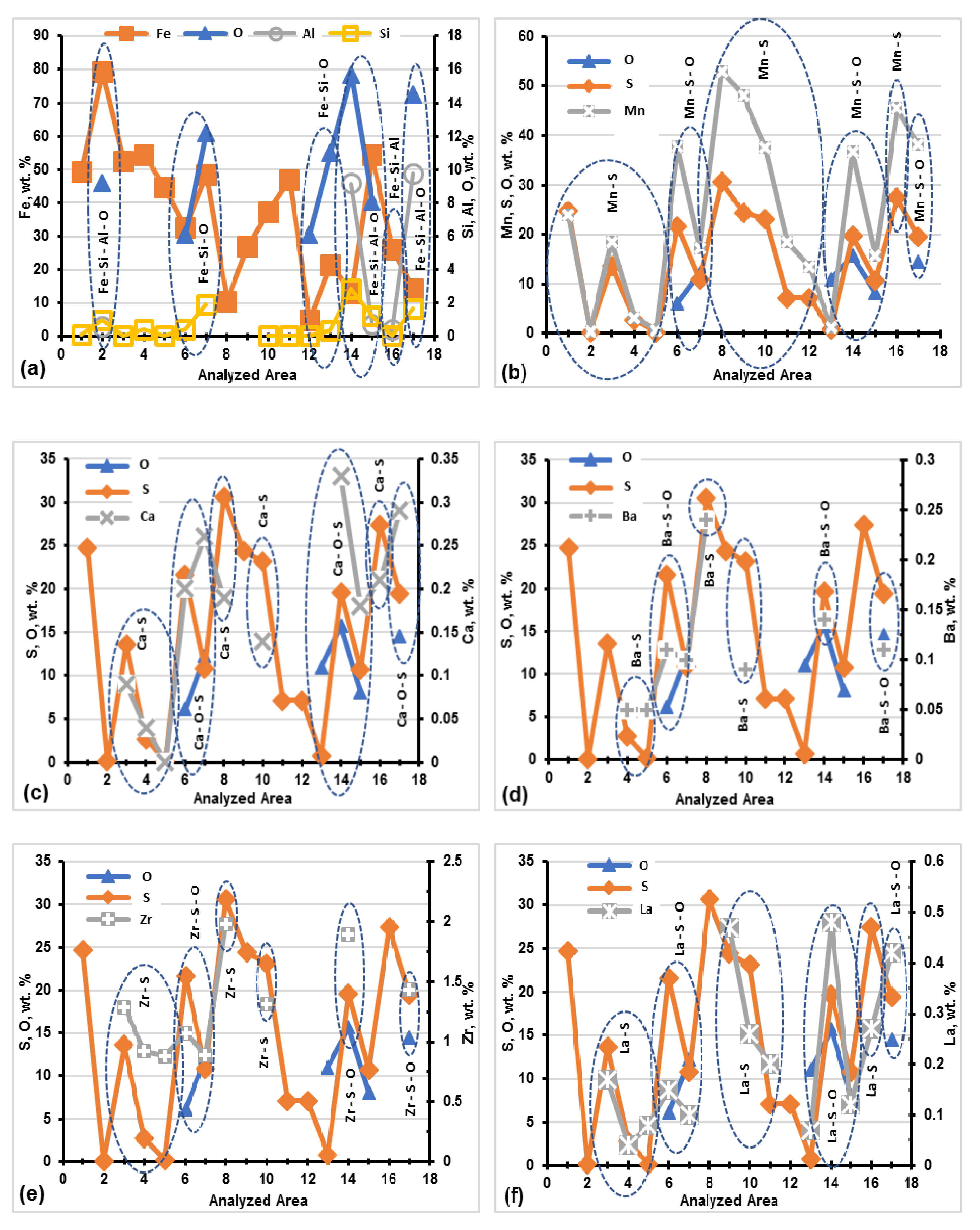
  • The obtained results re-confirm the role of complex (Mn,X)S compounds at a micron size (1–10 μm) and with and without a visible nucleus as an oxide origin (0.1–3 μm), as major graphite nucleation sites.
  • For La,Ca,Ba,Al,Zr and S-FeSi treatment (0.035%S base iron), SEM analysis finds that the first formed micro-compound is a complex Al-silicate (including Zr, La, Ca, Ba), which supports the nucleation of the second compound formed (Mn,Ca,La)S.
  • The graphite nucleation capacity of MnS compound increases through the addition of inoculating elements which act on the first formed oxidic compound (favoring MnS formation) and by replacing Mn in the Mn-S compound, thereby decreasing the mismatch between this substance and the (0001) face of graphite.
  • Additionally, a possible thin (nano size) layer is identified at the sulfide–graphite interface, including oxide-forming elements (O–Al–Si–Ca–La), that is able to increase the capacity of (Mn,X)S to nucleate graphite (leading to better crystallographic compatibility).
  • La is identified in all of the three important areas of nucleants (the first formed oxidic nucleus, later nucleated Mn-sulfide and at sulfide-graphite interface), thereby increasing the inoculating efficiency of the elements.
  • With a very lower S-content (0.018%S), the La,Ca,Al–FeSi alloy still has a high efficiency, but more complex La-bearing alloys are recommended with a higher dendritic austenite amount (LaBaZrTi–FeSi) or with lower eutectic recalescence (LaBaZr–FeSi).
  • La has limited but specific benefits with an optimum content of 0.05–0.06%S in cast irons; a lower eutectic recalescence and maximum recalescence rate, higher GRF1 and lower GRF2 graphitizing factors and a lower value of the first derivative at the end of solidification are favorable conditions for decreasing the micro-shrinkage formation incidence.

Author Contributions

Data curation, E.S., I.R., M.C. and S.S.; investigation, E.S., I.R., M.C. and S.S.; methodology, E.S., I.R., M.C. and S.S.; writing—original draft, E.S., I.R., M.C. and S.S. All authors have read and agreed to the published version of the manuscript.

Funding

This research received no external funding.

Conflicts of Interest

The authors declare no conflict of interest.

References

  1. Riposan, I.; Skaland, T. Modification and inoculation of cast iron. In Cast Iron Science and Technology Handbook; Stefanescu, D.M., Ed.; American Society of Materials: Cleveland, OH, USA, 2017; pp. 160–176. [Google Scholar]
  2. Riposan, I.; Chisamera, M.; Stan, S. The Role of Compounds in Graphite Formation in Cast Iron—A Review. Mater. Sci. Forum. 2018, 925, 3–11. [Google Scholar] [CrossRef] [Green Version]
  3. Chisamera, M.; Riposan, I.; Stan, S.; Skaland, T. Effects of Calcium and Strontium Inoculation on Undercooling, Chill and Microstructure in Grey Irons of Varying Sulphur and Oxygen Contents. In Proceedings of the 64th World Foundry Congress, Paris, France, 27 September 2000; p. 62. [Google Scholar]
  4. Zhou, J. Colour Metallography of Cast Iron. China Foundry 2009, 6, 52–69. [Google Scholar]
  5. Loper, C.R., Jr.; Gundlach, R.B. Inoculation what is it and How Does Inoculation Work. In Proceedings of the AFS International Inoculation Conference, Rosemont, IL, USA, 6–8 April 1998; p. 1. [Google Scholar]
  6. Loper, C.R., Jr. Inoculation of Cast Iron-Summary of Current Understanding. AFS Trans. 1999, 107, 523–528. [Google Scholar]
  7. Rong De, L.; Xiang, Y.J. Heteregeneous Nuclei in Flake Graphite. AFS Trans. 1991, 99, 707–712. [Google Scholar]
  8. Alonso, G.; Stefanescu, D.M.; Larranaga, P.; De la Fuente, A.; Suarez, R. On the Nucleation of Graphite in Lamellar Graphite Cast Iron. AFS Trans. 2016, 124, 124–134. [Google Scholar]
  9. Gundlach, R. Honorary cast iron lecture, Div. 5 AFS. In Proceedings of the 112nd AFS Metalcasting Congress, Atlanta, GA, USA, 17–20 May 2008; pp. 8–158. [Google Scholar]
  10. Riposan, I.; Chisamera, M.; Stan, S.; Toboc, P.; Ecob, C.; White, D. Three-stage Model for the Nucleation of Graphite in Grey Cast Iron. Mater. Sci. Technol. 2008, 24, 578–584. [Google Scholar] [CrossRef]
  11. PreseedTM Preconditioner Booklet. 2007 ELKEM Foundry Products Division. Available online: www.foundry.elkem.com (accessed on 7 December 2020).
  12. Riposan, I.; Chisamera, M.; Stan, S.; Stefan, E.; Hartung, C. Role of Lanthanum in Graphite Nucleation in Grey Cast Iron. Key Eng. Mater. 2011, 457, 19–24. [Google Scholar] [CrossRef]
  13. Riposan, I.; Stefan, I.C.; Firican, M.C.; Stan, S.; Naro, R.L.; Williams, D.C. Increasing the Inoculant Potency of Commercial Inoculating Alloys in Induction Melting Grey Cast Iron. AFS Trans. 2015, 123, 227–242. [Google Scholar]
  14. Sommerfeld, A.; Tonn, B. Theory of Graphite Nucleation in Lamellar Graphite Cast iron. Int. J. Met. 2009, 3, 39–47. [Google Scholar] [CrossRef]
  15. Campbell, J.A. A Hypothesis for Cast Iron Microstructures. Metall. Mater. Trans. B 2009, 40, 786–801. [Google Scholar] [CrossRef]
  16. Igoraski, V.; Okada, S. Observation and Analysis of the Nucleus of Spheroidal Graphite in Mg-treated Iron. Int. J. Cast Met. Res. 1998, 11, 83–88. [Google Scholar]
  17. Alonso, G.; Larranaga, P.; Stefanescu, D.M.; De la Fuente, E.; Natxiondo, E.; Suarez, R. Kinetics of Nucleation and Growth of Graphite at Different Stages of Solidification for Spheroidal Graphite Iron. Int. J. Met. 2017, 11, 14–26. [Google Scholar] [CrossRef]
  18. Solberg, J.K.; Onsoien, M.I. Nuclei for Heterogeneous Formation of Graphite Spheroids in Ductile cast Iron. Mater. Sci. Technol. 2001, 17, 1238–1242. [Google Scholar] [CrossRef]
  19. Nakae, H.; Igarashi, Y. Influence of Sulfur on Heterogeneous Nucleus of Spheroidal. Mater. Trans. 2002, 43, 2826–2831. [Google Scholar] [CrossRef]
  20. Stefan, E.; Riposan, I.; Chisamera, M. Application of Thermal Analysis in Solidification Pattern Control of La-Inoculated Grey Cast Irons. J. Therm. Anal. Calorim. 2019, 138, 2491–2503. [Google Scholar] [CrossRef]
  21. Stefan, E.; Chisamera, M.; Riposan, I. Chill sensitiveness and thermal analysis parameters relationship in hypo-eutectic, Ca and Ca-La inoculated commercial grey cast irons. In Proceedings of the CEEC-TAC 5 & MEDICTA2019 Conference,Roma, Italy, 27–30 August 2019.Central and Eastern European Committee for Thermal Analysis and Calorimetry. J. Min. Metall. Sect. B-Metall. 2020, 56, 387–396. [Google Scholar] [CrossRef]
  22. QuiK-Cup® QuiK-Lab® E. Thermal Analysis of Cast Iron. Available online: https://www.heraeus.com/media/media/hen/doc_hen/measurement_instruments/quik-cup.pdf (accessed on 20 June 2020).
  23. Stan, S.; Chisamera, M.; Riposan, I.; Stefan, E.; Barstow, M. Solidification pattern of un-inoculated and inoculated gray cast irons in wedge test samples. AFS Trans. 2010, 118, 295–309. [Google Scholar]
  24. Wang, B.; Fu, D.; Shan, G. Effect of Rare-earth Element Lanthanum on Structure and Performance of Gray Casting Iron. Hot Work. Technol. 2008, 13. Available online: http://en.cnki.com.cn/Article_en/CJFDTOTAL-SJGY200813010.htm (accessed on 7 December 2020).
  25. Standard A367-85: Standard Test Methods of Chill Testing of Cast Iron; American Society for Testing of Materials: West Conshohocken, PA, USA, 2000; pp. 151–154.
  26. Sillen, R.V. Novacast Technologies. 2006. Available online: www.novacast.se (accessed on 7 December 2020).
Figure 1. Influencing factors on three-stage graphite formation in gray cast irons.
Minerals 10 01146 g001
Figure 2. Cooling curve parameters (a) and results of the La,Ca,Al-FeSi inoculation (b) (Program I).
Minerals 10 01146 g002
Figure 3. Atypical example of chemical analysis along a cross-section of complex (Mn,X)S compounding La,Ca,Al-FeSi inoculated gray cast iron (Program I): (a) Compo image; (b) Mn, S; (c) O, Al, Si; (d) Ca, La.
Minerals 10 01146 g003
Figure 4. Relative performance of tested inoculants as representative temperatures on the cooling curves.
Minerals 10 01146 g004
Figure 5. Eutectic recalescence ΔTr and the maximum recalescence rate (TEM) (a), graphitizing factors GRF1 and GRF2 (b) and the chill tendency (c) of Ca-FeSi and La,Ca-FeSi inoculated gray cast irons (Program III).
Minerals 10 01146 g005aMinerals 10 01146 g005b
Figure 6. The analyzed compounds (chemical composition, Table 4) in connection with graphite (AD,F,H), embedded in graphite particle (G) and embedded in the metal matrix (E).
Minerals 10 01146 g006
Figure 7. Chemical composition on the cross section of the F-compound (Figure 6): (a) S, Mn, Mn/S; (b) Si, Ca, Ba, La, Zr.
Minerals 10 01146 g007
Figure 8. Chemical composition on the cross section of the H-compound (Figure 6): (a)-S, Mn; (b) Ca, Ba and La; (c) O,Al,Si,Zr.
Minerals 10 01146 g008
Figure 9. Elements associated in chemical composition, in different analyzed areas of compounds (see Figure 6. Table 4), embedded in metal matrix and connected with graphite particles: (a) Fe-Si-Al-O; (b) Mn-O-S; (c) Ca-O-S; (d) Ba-O-S; (e) Zr-O-S; (f) La-O-S; (1….17, Analyzed areas, Table 4).
Minerals 10 01146 g009
Table 1. Experimental programs.
ProgramSulfur(%Mn) × (%S)FeSi-Alloys
(wt.%, Technique)
CE%Inoculation
Objectives
Analyses *
Level/wt.%
ILow/0.0260.015La,Ca,Al
[0.15, Ladle]
3.69La-Efficiency in Low-S Gray Cast IronCC/Chill
Structure
SEM
IIVery Low/0.0180.008La,Ca,Al
La,Ca,Al + Zr/Ba/Zr,Ba/Zr,Ti/Zr,Ba,Ti
[0.10, In mold]
4.11Efficiency of Zr/Ba/Ti/addition to La-bearing FeSi, in very low S-Gray Cast IronCC
Structure
IIIMedium/0.046–0.0560.024–0.029Ca,Al
Ca,Al + La
[0.25, Ladle]
3.77La-addition to Ca,Al-FeSi, for optimum Mn-S relationshipCC
Chill
IVRelative Low/0.0350.0014La,Ca,Ba,Al,Zr,S
[over-inoculation]
[1.5, In Mold]
4.00Graphite nucleants analysisSEM
* CC—cooling curves analysis.
Table 2. Chemical composition of test gray cast irons (wt.%).
PrCSiMnPSAlTiCaLaCeMgCE
I3.191.600.570.0680.0260.0030.0050.00550.00230.0020.0013.69
II3.771.110.440.0200.0180.00150.00220.0040.00050.0020.00044.11
III3.231.750.530.140.0560.00370.0140.0070.00490.00080.00133.77
IV3.471.660.400.0930.0350.00110.0030.00170.00010.00230.00014.0
Table 3. Size of the Wedge Samples ASTM A 367-11 (2017).
SampleParameters of Wedge Samples *
BHALength
in.mmin.mmdegin.mm
W 10.205.11.0025.411.54101.6
W 20.4010.21.2531.8184101.6
W 30.7519.11.5038.1284101.6
   W 31/21.0025.41.7544.4325127.0
W 41.2531.82.0050.834.56152.4
* B—the maximum width, H—the height and A—the angle of the test wedge samples.
Table 4. Chemical composition, wt. %.
Co *Analyzed Area **COFeAlSiSCaBaLaMnZr
AreaFigure 9
AC-C1--49.6-0.1224.7---23.9-
BC-C29.59.279.30.590.970.11---0.31-
CC-C313.7-52.6-0.0413.60.09 0.1718.51.29
C-B438.1-54.5-0.432.720.040.050.043.190.92
C-G553.5-44.7-0.050.18-----
DC-C6-6.132.6-0.4621.60.20.110.1537.71.07
C-G77.712.248.7-1.9510.90.260.100.1017.30.89
EC-C8--10.6--30.60.190.243.453.11.98
C-B9--27.0--24.4--0.4748.2-
FC-C10--37.5-0.0623.10.140.090.2637.51.31
C-G1127.3-47.0-0.047.1--0.218.4-
GC-G1268.56.14.9-0.037.1---13.4-
C-G13651121.6-0.40.74--0.071.27-
HC-C14-14.514.39.751.6719.40.290.110.4238.11.43
C-C15-15.713.29.182.8419.60.330.140.4836.61.89
C-B16--26.20.380.0727.40.21-0.2745.5-
C-G178.08.154.40.741.2410.80.18-0.1215.6-
* Co—Compounds (Figure 6); ** Analyzed Area: C-C—Compound Centre; C-B—Compound Body; C-G—Compound—Graphite Interface; Mx—Metal Matrix; (G)—Compound embedded in graphite.
Publisher’s Note: MDPI stays neutral with regard to jurisdictional claims in published maps and institutional affiliations.

