
New Security Development and Trends to Secure the SCADA Sensors Automated Transmission during Critical Sessions


Abstract
:1. Introduction

- (i)
- The SCADA/DNP3 polling scenario called automated polling is addressed and, according to communication requirements, security is deployed to secure the sensitive information. The sensitive information would be secured before travelling to non-proprietary protocols over the Internet.
- (ii)
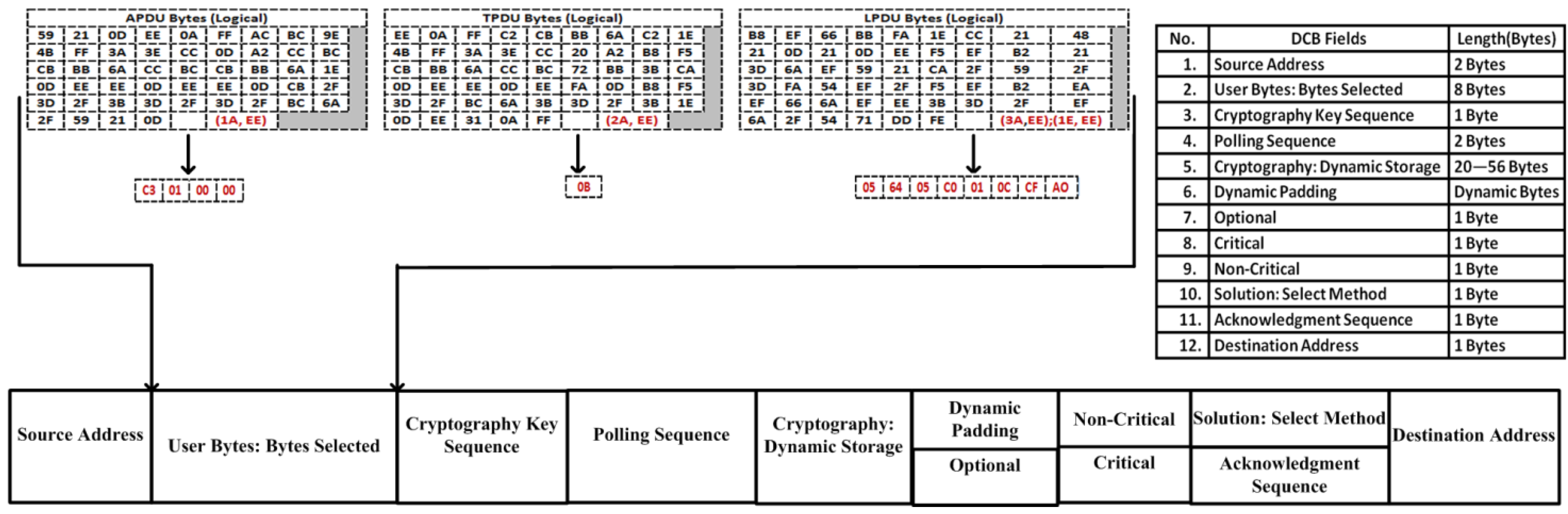
- To achieve security, the DNP3 stack is designed with an open source library, the original stack bytes are controlled and manipulated by new 56-byte dynamic development called a dynamic cryptography buffer (DCB), without changing the original protocol design.
2. DNP3

| Function Type | Function Code | Function Perform |
|---|---|---|
| Request Function Codes | ||
| Transfer Function | 0 | Confirm |
| 1 | Read | |
| 2 | Write | |
| Control Function | 3–6 | – |
| Freeze Function | 7–12 | – |
| Application Control Function | 13–18 | – |
| Configuration Function | 19–22 | – |
| Time Synchronization | 23 | – |
| Reserved | 24–128 | – |
| Response Function Codes | ||
| Response Function | 0 | Confirm |
| 129 | Read | |
| 130 | Write | |


3. Problem Statement
3.1. Background Study
3.2. Study Motivation
- (i)
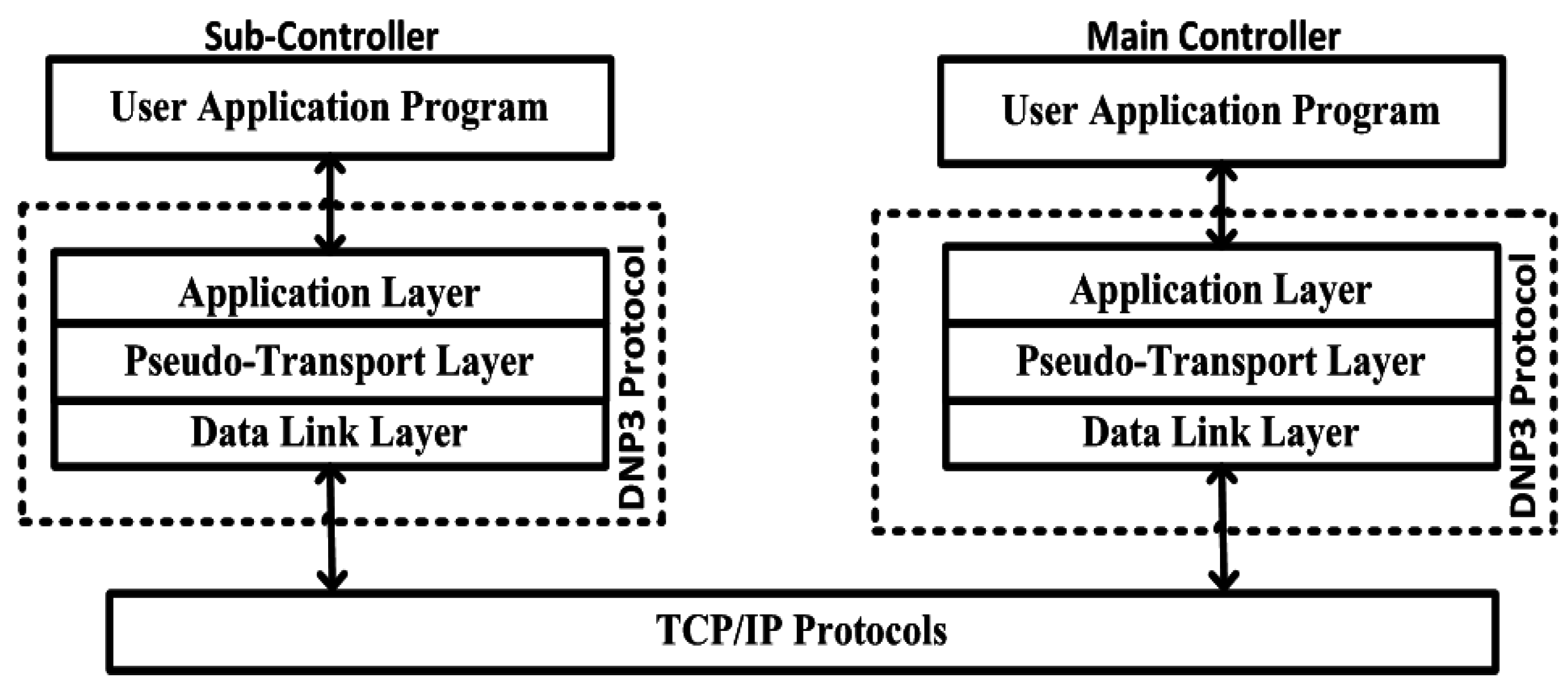
- The SCADA/DNP3 stack has been designed using an open source library with explicit codes in C#, and security is implemented within the stack, before it communicates with open protocols.
- (ii)
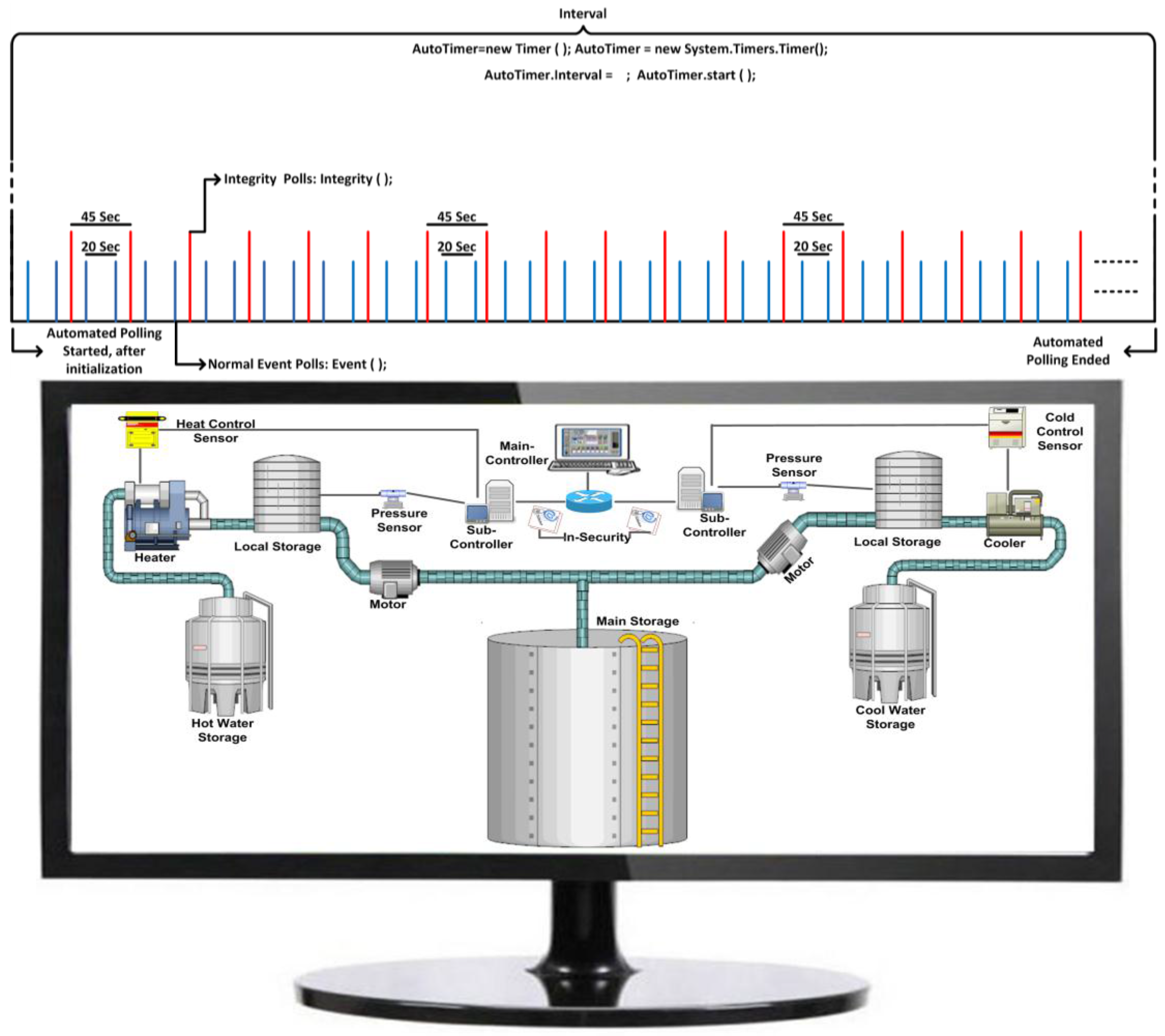
- A new automated polling scenario has been designed that combines the balanced and unbalanced systems of DNP3, according to the requirements of the organization in a water pumping system.
- (iii)
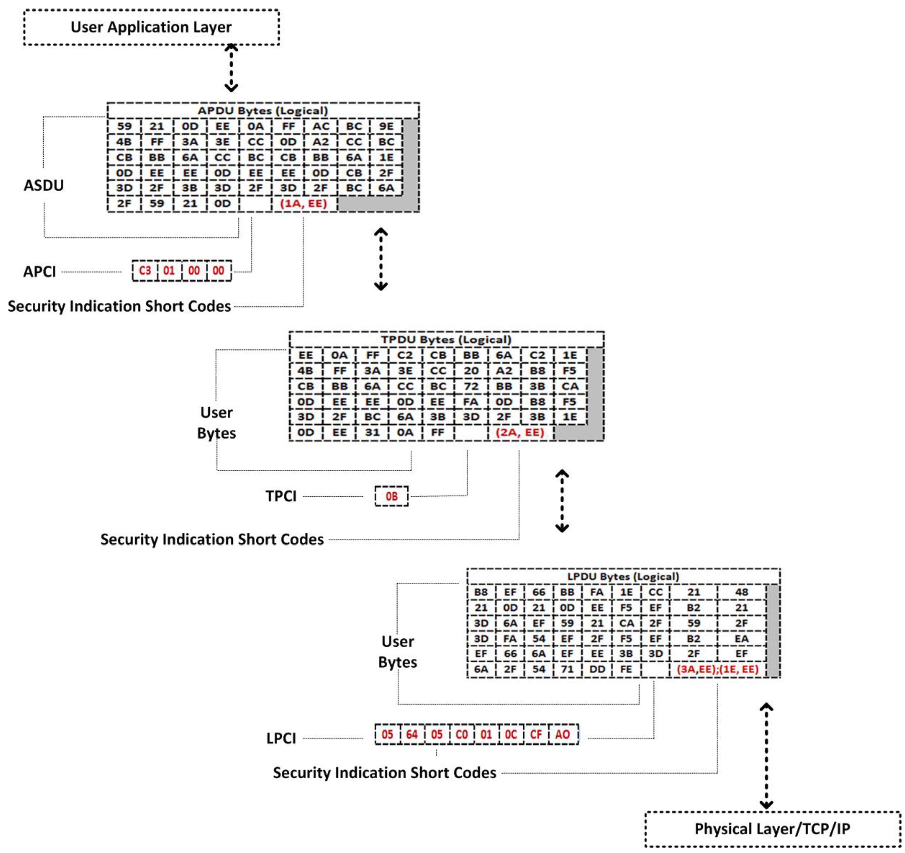
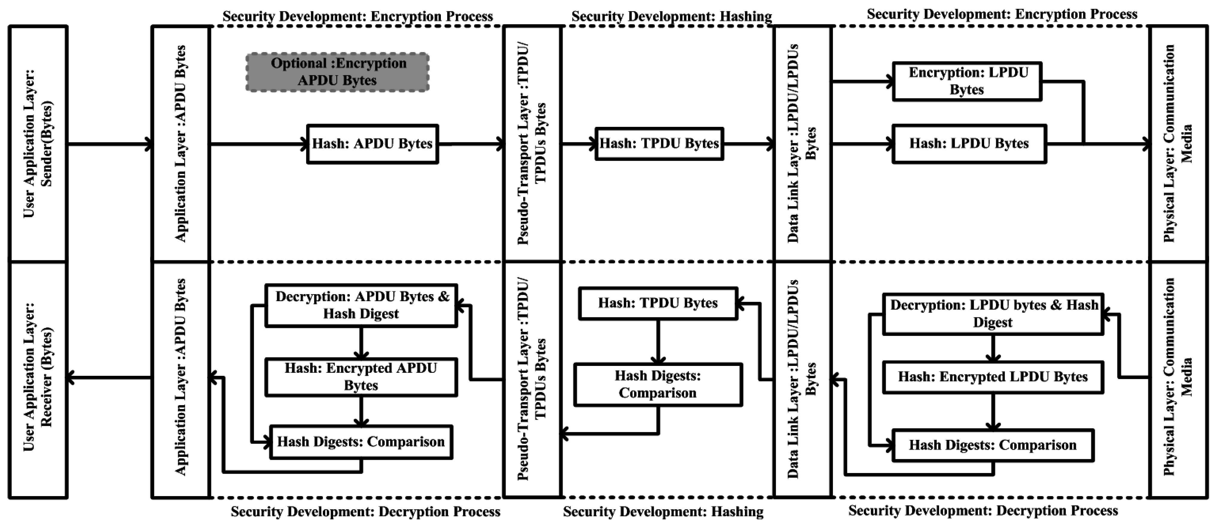
- In the original DNP3 stack, bytes are constructed followed by layer(s) specifications, and security is deployed, and then, bytes are placed in a dynamic cryptography buffer (DCB) for further development. In security development, well-known security algorithms are selected from the arena of cryptography, such as advanced encryption standard (AES) and SHA-2, which significantly enhance SCADA/DNP3 security without interrupting the communication (or polling) specifications.
- (iv)
- A simulation environment is designed for the SCADA system by employing DNP3; bytes are constructed with security development, and are transmitted a number of times between controllers in the SCADA/DNP3 network.
- (v)
- Formal proofs are used which validate the proposed research, including the validation of the bytes construction processes within the stack, validation of security implementation and validation of DCB design and development.
- (vi)
- Well-known tools (or attacking tools) are used that interrupt the normal communication of the SCADA/DNP3 system that we can use to measure and evaluate performance.
- (vii)
- An evaluation process is performed based on three measurements phases:
- (a)
- The DNP3 bytes are constructed without security concerns, and transmitted to an open network. Attacking tools are used to interrupt the normal communication, and security performance is measured.
- (b)
- In the second phase, proposed security is implementing via DCB, and performance results are computed.
- (c)
- In the last phase, cryptography algorithms such as AES and SHA-2 are deployed and tested at each end of SCADA/DNP3 system and performances are computed that would be helpful during the comparison process.The above three measurements are helpful during the comparison process, as well as at the time of evaluation. The measured results of the second phase are further compared with existing developments (results) that would show the difference between them.
4. Model Design and Development
4.1. DNP3 Model Design and Security Development


4.2. Model Definitions
5. Protocol Bytes and DCB


6. Testbed Setup

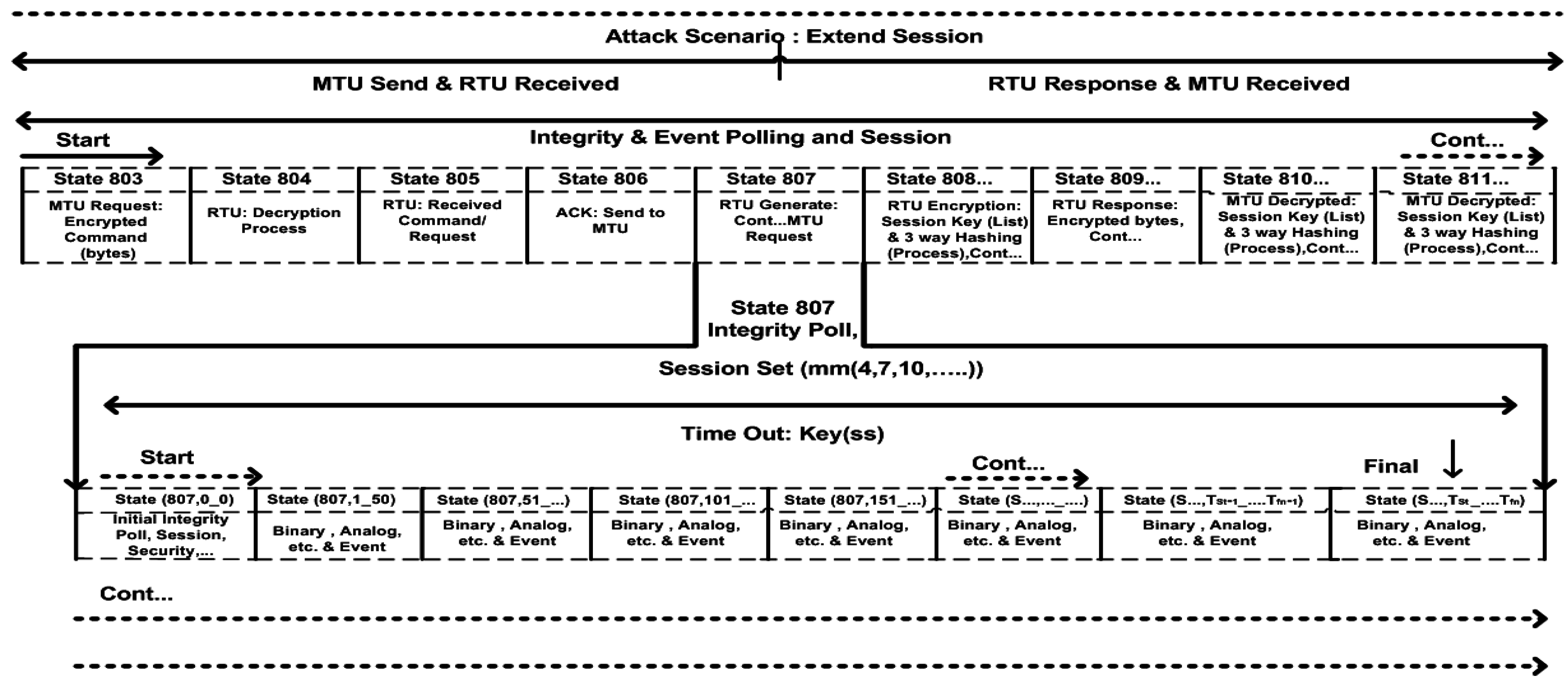
7. Automated Polling Design and Flow

| 804, 805 | Remote station decrypted the message (bytes) and bytes received. | S-Solution2 |
| 806 | Acknowledgement: From RTU to MTU. | S-Solution2 |
| 807 | The Integrity Poll: Remote station generates continuously response. | S-Solution1 |
| (807, 0_0) __ | The Integrity Poll: Generate continuously response. | S-Solution1 |
| 808…, 809,… | RTU: Encryption process. | S-Solution1 |
| 810…, 811,… | MTU: Decryption process. | S-Solution1 |


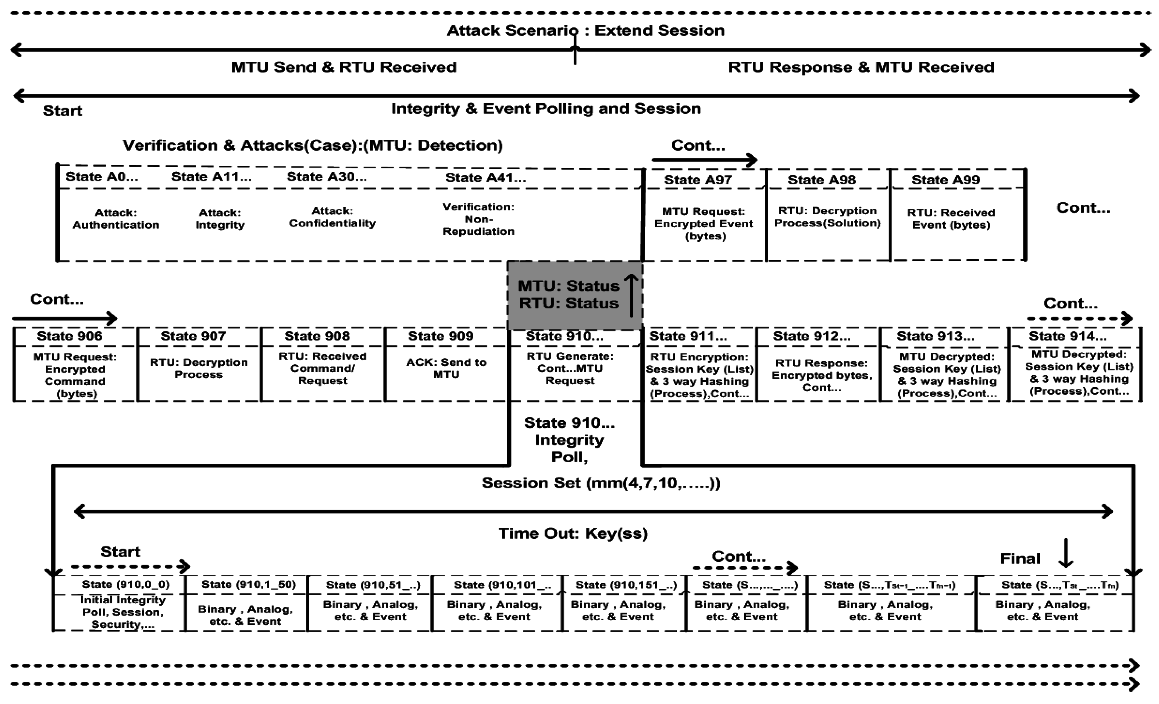
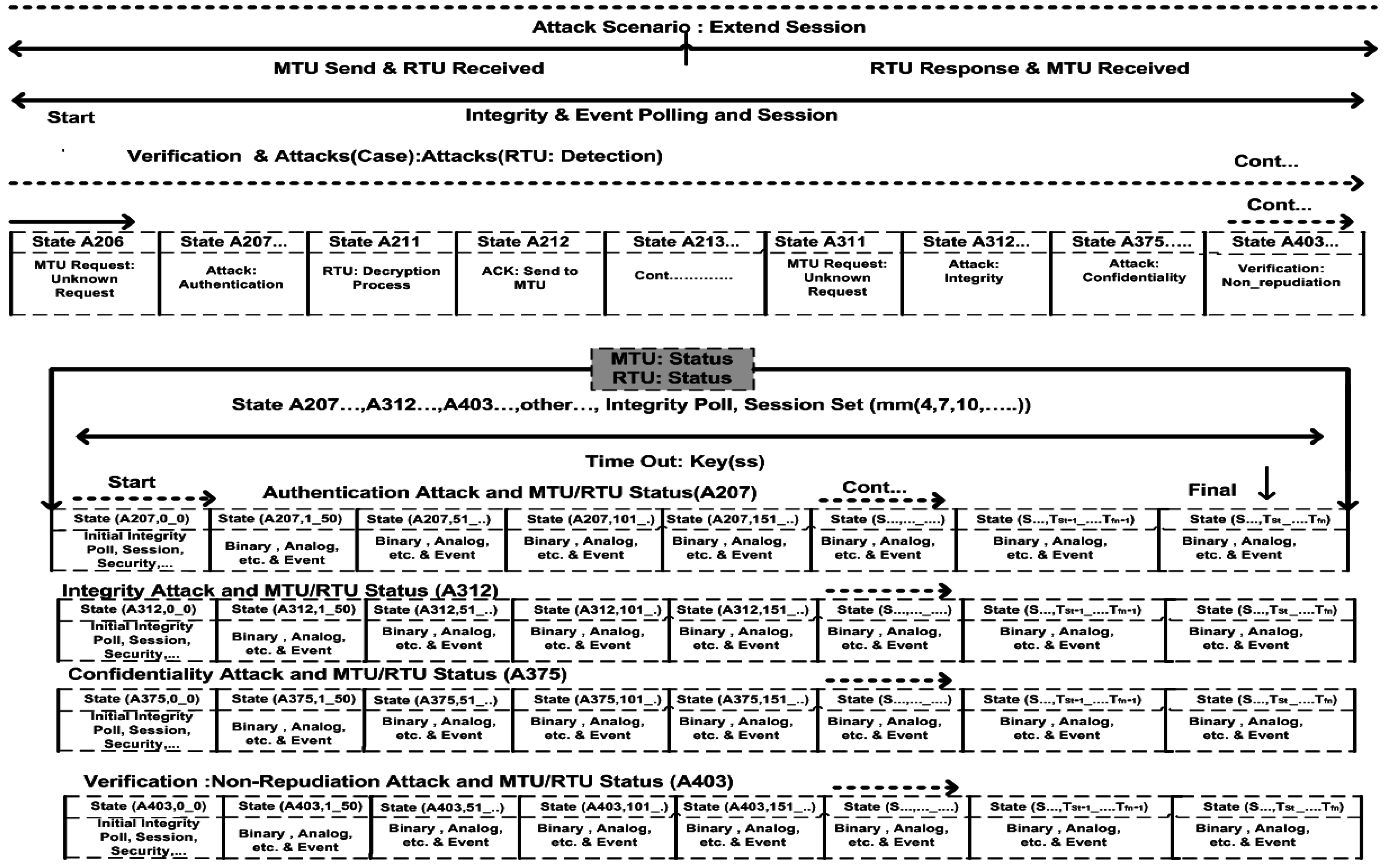
| MTU: State (Logical) | MTU: Process | RTU: State (Logical) | RTU: Process |
|---|---|---|---|
| 906 | MTU Request: Encryption process (bytes). | A206 | Unknown bytes. |
| 907 | RTU Decryption process (bytes). | A207 | Authentication Attacks: Verification. |
| 908 | RTU has received MTU request. | A211 | RTU: Decryption process. |
| 909 | Acknowledgement. | A212 | Acknowledgement. |
| 910 | The Integrity Poll: Remote station generates continuously response. | (A207, 0_0)__ | Generate continuous response: Verification process |
| (910, 0_0)__ | The Integrity Poll: Generate continuously response. | A213 | Continuous response |
| A0 | Abnormal Communication: Detection of Authentication Attacks. | A311 | Unknown bytes. |
| A11 | Abnormal Communication: Detection of Confidentiality Attacks. | A312 | Integrity Attacks: Verification and Continuous |
| A30 | Abnormal Communication: Detection of Integrity Attacks. | (A312, 0_0)__ | Generate continuous response: Verification process. |
| A41 | Abnormal Communication: Detection of Non-Repudiation Attacks (Optional). | A375 | Confidentiality Attacks: Verification and continuous |
| A97 | MTU Request: Event (in-case, RTU does not reply or in Abnormal scenario). | (A375, 0_0)__ | Generate continuous response: Verification process. |
| A98 | RTU Decryption: Event (Incase, RTU does not reply or Abnormal scenario). | A403 | Non-Repudiation Attacks: Verification and continuous. |
| A99 | RTU has received MTU request and process continuous……. | (A403, 0_0)__ | Generate continuous response: Verification process. |
| 911…, 912,.. | RTU: Encryption process | – | – |
| 913…, 914,.. | MTU: Decryption process | – | – |
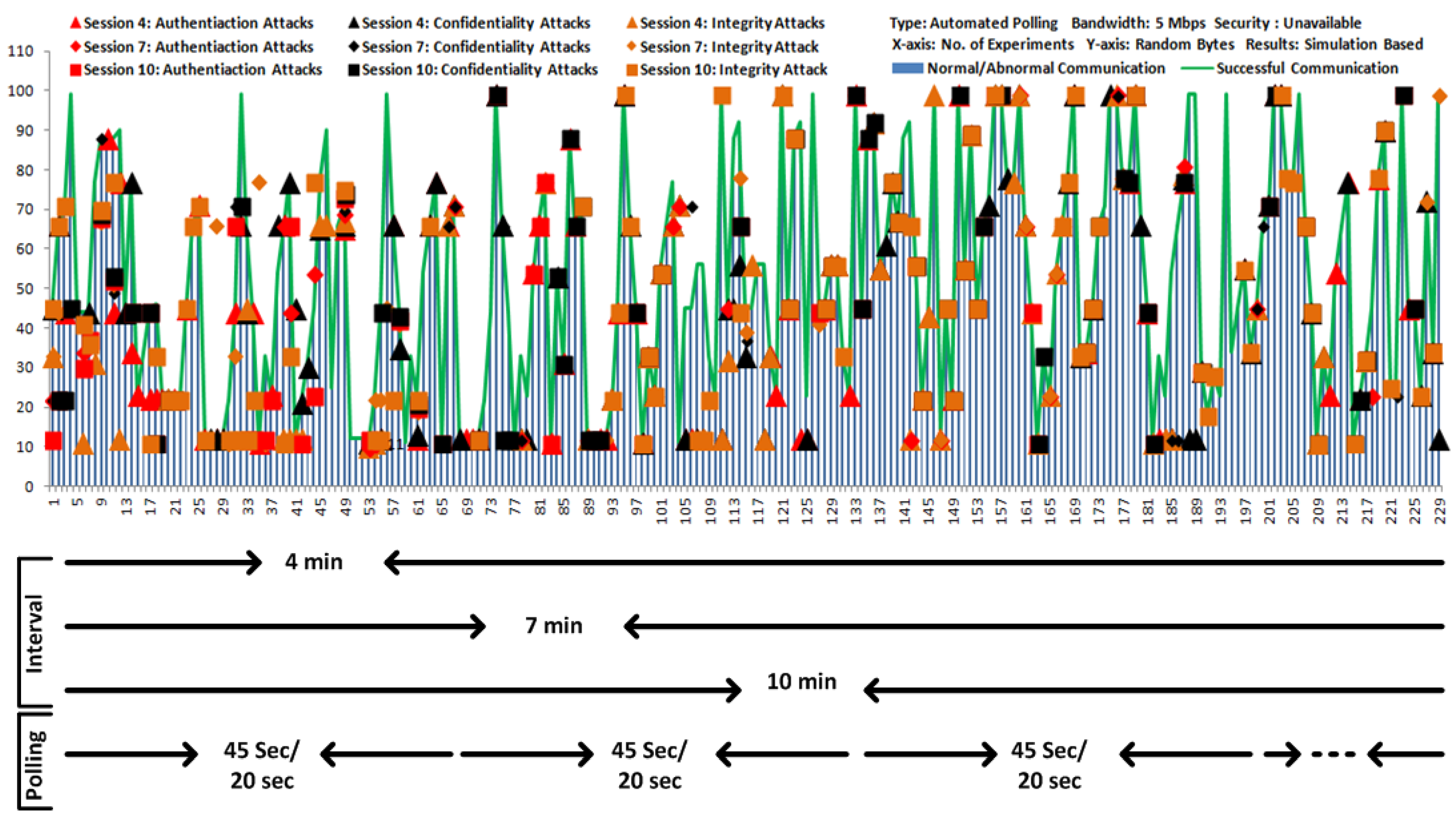
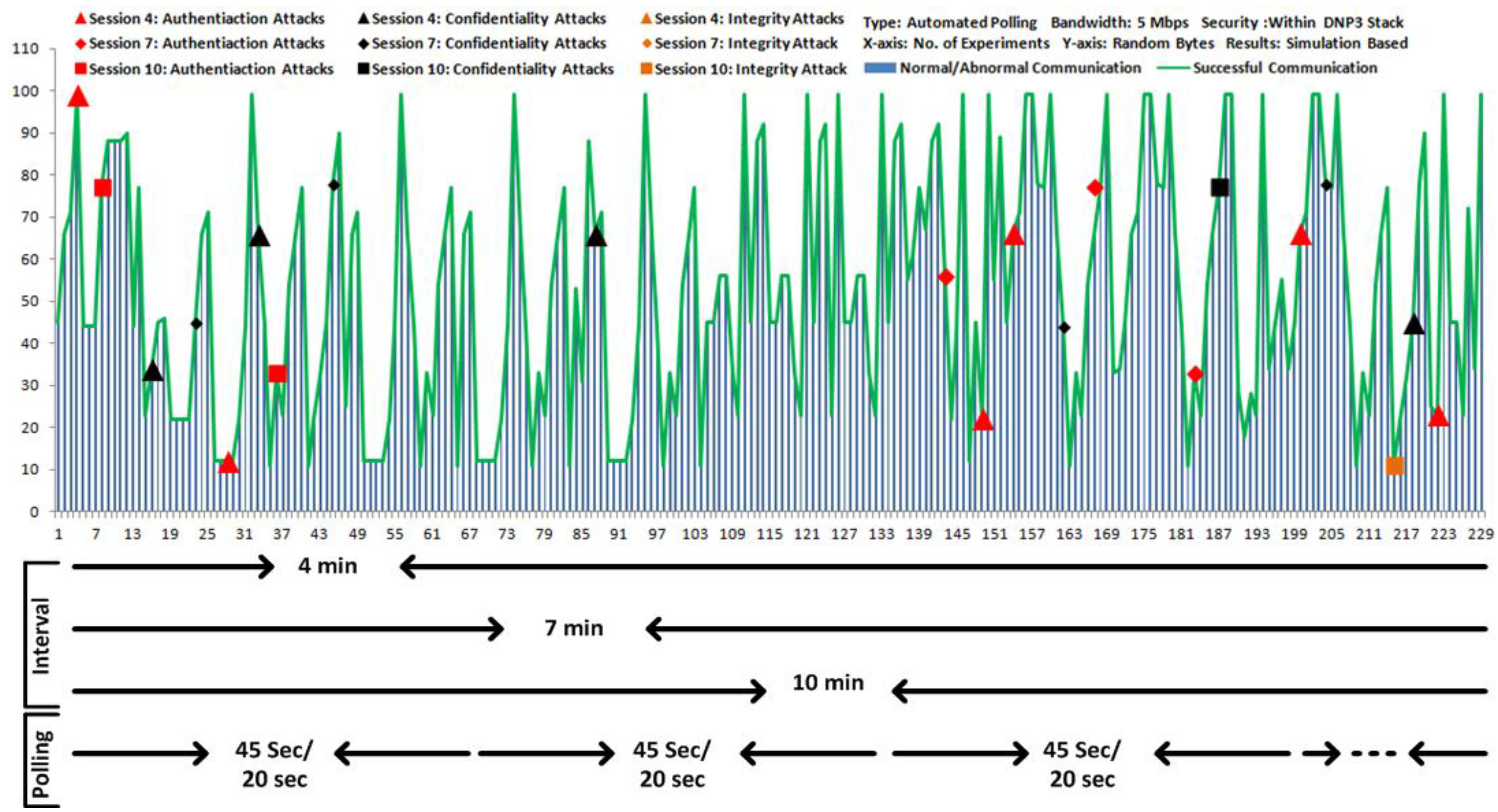
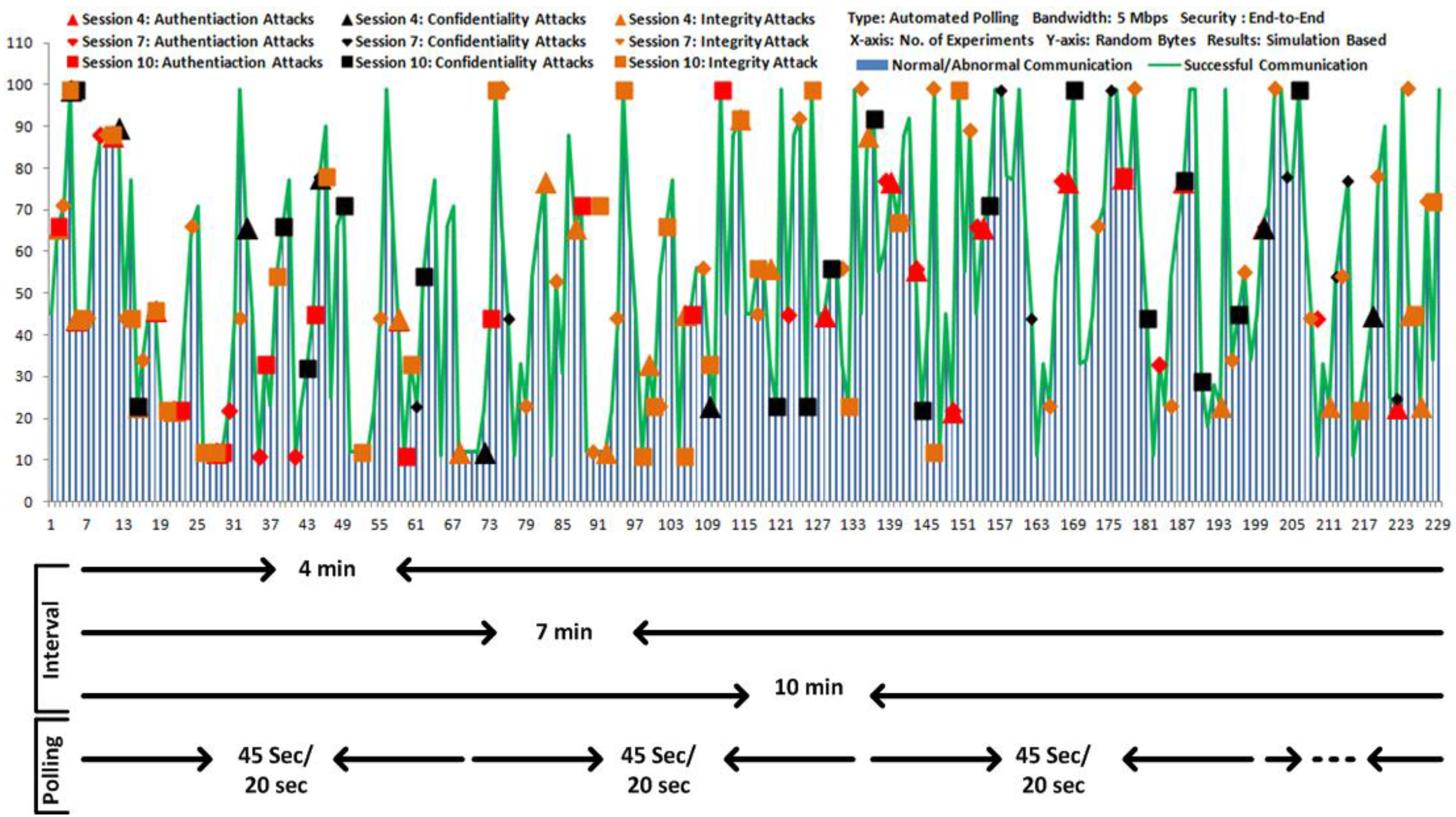
8. Performance Measurement and Discussion
- In the first scenario, the attacks are launched but DNP3 model is designed without security;
- In the second scenario, the attacks are launched and the DNP3 model is designed with security development, and
- In the third scenario, security is deployed at each end of the automated polling, and performance is observed against attacks. These scenarios are also useful to compare the overall computed performances.
| Authentication | Cracking Tools, Sniffer, Dsniff, Winsniffer and Password Dictionary | Guessing Shared Key, Brute Force and Password Guessing |
| Confidentiality | Ethereal, Ettercap, Kismet, Aircrack, Airsnort, Dsniff, and Ettercap | Eavesdropping, Key Cracking and Man-in-the-Middle |
| Integrity | Airpwn, File2air, Dinject/Reinject, Capture and Injection Tools, Jamming and Injection Tools | Frame Injection, Data Replay and Data Deletion |
Attack Detection and Security


- Attack Detection (%) =
- The values compute the attacks which are detected at specified intervals, and added to compute the total. The value computes and adds the number of experiments performed at each interval. Where, and show the sequence with limit .
- For example, experiments per interval and total experiments per scenario are: 228 and 684.

9. Related Work
10. Conclusions and Future Work
Acknowledgments
Author Contributions
Conflicts of Interest
References
- Stouffer, J.; Kent, K. Guide to Supervisory Control and Data Acquisition (SCADA) and Industrial Control Systems Security; Recommendations of the National Institute of Standards and Technology; NIST: Gaithersburg, MD, USA, 2006; pp. 2–13. [Google Scholar]
- National Communications System. Supervisory Control and Data Acquisition (SCADA) Systems; Technical Information Bulletin 04-1; National Communications System: Arlington, TX, USA, 2004; pp. 8–12. [Google Scholar]
- Clarke, G.; Reynders, D.; Wright, E. Practical Modern SCADA Protocols; DNP3, 60870.5 and Related Systems; Elsevier: New York, NY, USA, 2004; pp. 73–129. [Google Scholar]
- Susanto, I.; Jackson, R.; Paul, D.L. Industrial Process Control System Security. Wiley Handbook of Science and Technology for Homeland Security; John Wiley & Sons: Hoboken, NJ, USA, 2009; pp. 1–15. [Google Scholar]
- DNP Users Group. DNP3 Application Layer Specification, Version 2.00; DNP Organization: Washington, WA, USA, 2005; Volume 2. [Google Scholar]
- Gao, J.; Liu, J.; Rajan, B.; Nori, R. SCADA Communication and Security Issues. Secur. Commun. Netw. 2014, 7, 175–194. [Google Scholar] [CrossRef]
- Kim, H.J. Security and Vulnerability of SCADA Systems over IP-Based Wireless Sensor Networks. Int. J. Distrib. Sens. Netw. 2012, 2012. [Google Scholar] [CrossRef]
- Musa, S.; Shahzad, A.; Aborujilah, A. Secure Security Model Implementation for Security Services and Related Attacks Based on End-to-End, Application Layer and Data Link Layer Security. In Proceedings of the 7th International Conference on Ubiquitous Information Management and Communication, Kota Kinabalu, Malaysia, 17–19 January 2013.
- Hong, S.; Lee, M. Challenges and Direction toward Secure Communication in the SCADA System. In Proceedings of the 2010 Eighth Annual Communication Networks and Services Research Conference (CNSR), Montreal, QC, Canada, 11–14 May 2010.
- Hieb, J.L.; Graham, J.H.; Patel, S.C. Cyber Security Enhancements for SCADA and DCS Systems; Intelligent Systems Research Laboratory; Technical Report ISRL-TR-07-02; University of Louisville: Louisville, KY, USA, 2007. [Google Scholar]
- Hieb, J.; Graham, J.; Patel, S. Security Enhancements for Distributed Control Systems. In Critical Infrastructure Protection, IFIP International Federation for Information Processing; Springer US: New York, NY, USA, 2008; Volume 253, pp. 133–146. [Google Scholar] [CrossRef]
- Kang, D.-J.; Kim, H.-M. A Proposal for Key Policy of Symmetric Encryption Application to Cyber Security of KEPCO SCADA Network. In Proceedings of the Future Generation Communication and Networking, (FGCN 2007), Jeju, Korea, 6–8 December 2007; Volume 2.
- Moral-Garcia, S.; Moral-Rubio, S.; Rosado, D.G.; Fernandez, E.B.; Fernandez-Medina, E. Enterprise Security Pattern: A New Type of Security Pattern. Secur. Commun. Netw. 2014, 7, 1670–1690. [Google Scholar] [CrossRef]
- Khelil, A.; Germanus, D.; Suri, N. Protection of SCADA communication channels. In Critical Infrastructure Protection, Proceedings of the Critical Infrastructure Protection Lecture Notes in Computer Science; Springer Berlin Heidelberg: Berlin, Germany, 2012; Volume 7130, pp. 177–196. [Google Scholar]
- Ali, M.; Khan, S.U.; Vasilakos, A.V. Security in Cloud Computing: Opportunities and Challenges. Inf. Sci. 2015, 305, 357–383. [Google Scholar] [CrossRef]
- Irshad, A.; Sher, M.; Faisal, M.S. A Secure Authentication Scheme for Session Initiation Protocol by Using ECC on the Basis of the Tang and Liu Scheme. Secur. Commun. Netw. 2014, 1210–1218. [Google Scholar] [CrossRef]
- Lim, S.; Lee, E.; Park, C.-M. Equivalent Public Keys and a Key Substitution Attack on the Schemes from Vector Decomposition. Secur. Commun. Netw. 2014, 1274–1282. [Google Scholar] [CrossRef]
- Patel, S.C. Secure Internet-Based Communication Protocol for SCADA Networks. Ph.D. Thesis, University of Louisville, Louisville, KY, USA, 2006. [Google Scholar]
- Patel, S.C.; Bhatt, G.D.; Graham, J.H. Improving the Cyber Security of SCADA Communication Networks. Commun. ACM 2009, 52, 139–142. [Google Scholar] [CrossRef]
- Igure, V.M.; Laughter, S.A.; Williams, R.D. Security Issues in SCADA Networks. Comput. Secur. 2006, 25, 498–506. [Google Scholar] [CrossRef]
- Elsaid, W.H. Enhanced Cryptographic Approaches for SCADA Network Security. Ph.D. Thesis, University of Louisville, Louisville, KY, USA, 2010. [Google Scholar]
- Saxena, A.; Pal, O.; Saquib, Z. Public Key Cryptography Based Approach for Securing SCADA Communications. In Computer Networks and Information Technologies; Communications in Computer and Information Science; Springer Berlin Heidelberg: Berlin, Germany, 2011; Volume 142, pp. 56–62. [Google Scholar]
- Shahzad, A.; Musa, S.; Irfan, M. N-Secure Cryptography Solution for SCADA Security Enhancement. Trends Appl. Sci. Res. 2014, 9, 381–395. [Google Scholar] [CrossRef]
- Drahansky, M.; Balitanas, M. Cipher for Internet-based Supervisory Control and Data Acquisition Architecture. J. Secur. Eng. 2011, 8, 337–348. [Google Scholar]
- Shbib, R.; Zhou, S.; Alkadhimi, K. SCADA System Security, Complexity, and Security Proof. In Proceedings of the ICPCA-SWS 2012, LNCS 7719, Istanbul, Turkey, 28–30 November 2012; pp. 405–410.
- Ryu, D.H.; Kim, H.; Um, K. Reducing Security Vulnerabilities for Critical Infrastructure. J. Loss Prev. Process Ind. 2009, 22, 1020–1024. [Google Scholar] [CrossRef]
- Shyamasundar, R.K. Security and Protection of SCADA: A Big Data Algorithmic Approach. In Proceedings of the 6th International Conference on Security of Information and Networks (SIN’13), Aksaray, Turkey, 26–28 November 2013; ACM: New York, NY, USA, 2013; pp. 20–27. [Google Scholar]
- Cardenas, A.A.; Amin, S.; Lin, Z.-S.; Huang, Y.-L.; Huang, C.-Y.; Sastry, S. Attacks against Process Control Systems: Risk Assessment, Detection, and Response. In Proceedings of the 6th ACM Symposium on Information, Computer and Communications Security (ASIACCS’11), Hongkong, China, 22–24 March 2011; ACM: New York, NY, USA, 2011; pp. 355–366. [Google Scholar]
- Ralston, P.A.S.; Graham, J.H.; Hieb, J.L. Cyber Security Risk Assessment for SCADA and DCS networks. ISA Trans. 2007, 46, 583–594. [Google Scholar] [CrossRef] [PubMed]
- Gold, S. The SCADA Challenge: Securing Critical Infrastructure. Netw. Secur. 2009, 2009, 18–20. [Google Scholar] [CrossRef]
- DNP Users Group. DNP3 Specification, Secure Authentication; DNP Organization: Washington, WA, USA, 2010; Supplement to Volume 2. [Google Scholar]
- Majdalawieh, M.; Parisi-Presicce, F.; Wijesekera, D. DNPSec: Distributed Network Protocol Version 3 (DNP3) Security Framework. In Advances in Computer, Information, and Systems Sciences, and Engineering, Proceedings of IETA 2005, TeNe 2005, EIAE 2005; Springer: Houten, The Netherlands, 2006; pp. 227–234. [Google Scholar]
- East, S.; Butts, J.; Papa, M.; Shenoi, S. A Taxonomy of Attacks on the DNP3 Protocol. In Critical Infrastructure Protection III; Springer Berlin Heidelberg: Berlin, Germany, 2009; pp. 67–81. [Google Scholar]
- Mander, T.; Cheung, R.; Nabhani, F. Power System DNP3 Data Object Security Using Data Sets. Comput. Secur. 2010, 29, 487–500. [Google Scholar] [CrossRef]
- Shahzad, A.; Kalum, P.U.; Young, K.L.; Soojin, P.; Malrey, L. The Sensors Connectivity within SCADA Automation Environment and New Trends for Security Development during Multicasting Routing Transmission. Int. J. Distrib. Sens. Netw. 2015, in press. [Google Scholar]
- Lee, D.; Kim, H.; Kim, K.; Yoo, P.D. Simulated Attack on DNP3 Protocol in SCADA System. In Proceedings of the The 31th Symposium on Cryptography and Information Security, Kagoshima, Japan, 21–24 January 2014.
- Mohammadi, N.B.; Misic, J.; Misic, V.B.; Khazaei, H. A Framework for Intrusion Detection System in Advanced Metering Infrastructure. Secur. Commun. Netw. 2014, 7, 195–205. [Google Scholar] [CrossRef]
- Mirkovic, J.; Reiher, P. A Taxonomy of DDoS Attack and DDoS Defense Mechanisms. ACM SIGCOMM Comput. Commun. Rev. 2004, 34, 39–53. [Google Scholar] [CrossRef]
- Jin, D.; Nicol, D.M.; Yan, G. An Event Buffer Flooding Attack in DNP3 Controlled SCADA Systems. In Proceedings of the 2011 Winter Simulation Conference (WSC), Phoenix, AZ, USA, 11–14 December 2011; pp. 2614–2626.
- Shahzad, A.; Xiong, N.; Irfan, M.; Lee, M.; Hussain, S.; Khaltar, B. A SCADA intermediate simulation platform to enhance the system security. In Proceedings of the 2015 17th International Conference on Advanced Communication Technology (ICACT), Seoul, Korea, 1–3 July 2015; pp. 368–373.
- Graham, J.; Patel, S. Security Considerations in SCADA Communication Protocols; Technical Report TR-ISRL-04-01; Intelligent Systems Research Laboratory: Louisville, KY, USA, 2004. [Google Scholar]
- Rrushi, D.; di Milano, U. SCADA Intrusion Prevention System. In Proceedings of the 1st CI2RCO Critical Information Infrastructure Protection Conference, Hampshire, UK, 14 March 2006.
- Bompard, E.; Gao, C.; Napoli, R.; Russo, A.; Masera, M.; Stefanini, A. Risk Assessment of Malicious Attacks Against Power Systems. IEEE Trans. Syst. Man Cybern. A Syst. Hum. 2009, 39, 1074–1085. [Google Scholar] [CrossRef]
- Fernandez, J.; Fernandez, A. SCADA Systems: Vulnerabilities and Remediation. J. Comput. Sci. Coll. 2005, 20, 160–168. [Google Scholar]
- Patel, S.; Yu, Y. Analysis of SCADA Security models. Int. Manag. Rev. 2007, 3, 68–76. [Google Scholar]
- Faruk, A. Testing & Exploring Vulnerabilities of the Applications Implementing DNP3 Protocol. Masters’ Dissertation, Royal Institute of Technology, Stockholm, Sweden, 2008. [Google Scholar]
- Hong, S.; Lee, S. Challenges and Perspectives in Security Measures for the SCADA System. In Proceedings of the 5th Myongji-Tsinghua University Joint Seminar on Protection & Automation, Korea, 2008.
- Fujisaki, E.; Okamoto, T. Secure Integration of Asymmetric and Symmetric Metric Encryption Schemes. In Advances in Cryptology—CRYPTO’99; LNCS; Springer Berlin Heidelberg: Berlin, Germany, 1999; Volume 1666, pp. 537–554. [Google Scholar]
- Rivest, R.L.; Shamir, A.; Adleman, L. A method for Obtaining Digital Signatures and Public-Key Cryptosystems. Commun. ACM 1978, 21, 120–126. [Google Scholar] [CrossRef]
- He, D.; Chen, J.; Chen, Y. A Secure Mutual Authentication Scheme for Session Initiation Protocol Using Elliptic Curve Cryptography. Secur. Commun. Netw. 2012, 5, 1423–1429. [Google Scholar] [CrossRef]
- Shahzad, A.; Musa, S.; Irfan, M.; Asadullah, S. Deployment of New Dynamic Cryptography Buffer for SCADA Security Enhancement. J. Appl. Sci. 2014, 14, 2487–2497. [Google Scholar] [CrossRef]
- Liyanage, M.; Gurtov, A. Securing Virtual Private LAN Service by Efficient Key Management. Secur. Commun. Netw. 2014, 7, 1–13. [Google Scholar] [CrossRef]
- Chandia, R.; Gonzalez, J.; Kilpatrick, T.; Papa, M.; Shenoi, S. Security Strategies for SCADA Networks. IFIP Int. Fed. Inf. Process. 2008, 253, 117–131. [Google Scholar]
- Rong, C.; Nguyen, S.T.; Jaatun, M.G. Beyond Lightning: A Survey on Security Challenges in Cloud Computing, Special Issue on Recent Advanced Technologies and Theories for Grid and Cloud Computing and Bio-Engineering. Comput. Electr. Eng. 2013, 39, 47–54. [Google Scholar] [CrossRef]
- Riaz, R.; Naureen, A.; Akram, A.; Akbar, V.; Kim, K.H.; Farooq Ahmed, H. A Unified Security Framework with Three Key Management Schemes for Wireless Sensor Networks. Comput. Commun. 2008, 31, 4269–4280. [Google Scholar] [CrossRef]
- Mohamed, F.A.; Hemayed, E.E. Using Trusted Computing in Trusted Mail Transfer Protocol. Secur. Commun. Netw. 2014, 7, 926–933. [Google Scholar] [CrossRef]
- Li, J.; Lin, Y.; Wang, G.; Li, R.; Yin, B. Privacy and Integrity Preserving Skyline Queries in Tiered Sensor Networks. Secur. Commun. Netw. 2014, 7, 1177–1188. [Google Scholar] [CrossRef]
- Chen, Y.; Dong, Q. RCCA Security for KEM + DEM Style Hybrid Encryptions and a General Hybrid Paradigm from RCCA-secure KEMs to CCA-secure encryptions. Secur. Commun. Netw. 2014, 7, 1219–1231. [Google Scholar]
- Raza, S.; Duquennoy, S.; Höglund, J.; Roedig, U.; Voigt, T. Secure Communication for the Internet of Things—A Comparison of Link-layer Security and IPsec for 6LoWPAN. Secur. Commun. Netw. 2014, 7, 2654–2668. [Google Scholar] [CrossRef]
- Morris, T.H.; Gao, W. Industrial control system cyber attacks. In Proceedings of the 1st International Symposium on ICS & SCADA Cyber Security Research; BCS: UK, 2013; pp. 22–29. [Google Scholar]
- Robles, R.J.; Balitanas, M.; Kim, T. Security Encryption Schemes for Internet SCADA: Comparison of the Solutions. Commun. Comput. Inf. Sci. 2011, 223, 19–27. [Google Scholar]
- Loutchkina, I.; Jain, L.C.; Nguyen, T.; Nesterov, S. Systems’ Integration Technical Risks’ Assessment Model (SITRAM). IEEE Trans. Syst. Man Cybern. Syst. 2014, 44, 342–352. [Google Scholar] [CrossRef]
- Wang, L.; Ren, S.; Korel, B.; Kwiat, K.A.; Salerno, E. Improving System Reliability against Rational Attacks Under Given Resources. IEEE Trans. Syst. Man Cybern. Syst. 2014, 44, 446–456. [Google Scholar] [CrossRef]
- Lin, C.-H.; Song, K.-T. Probability-Based Location Aware Design and on-Demand Robotic Intrusion Detection System. IEEE Trans. Syst. Man Cybern. Syst. 2014, 44, 705–715. [Google Scholar] [CrossRef]
- Jiang, Y.; Jiang, J.C. Diffusion in Social Networks: A Multiagent Perspective. IEEE Trans. Syst. Man Cybern. Syst. 2015, 45, 198–213. [Google Scholar] [CrossRef]
- Ko, J.; Lim, H.; Lee, S.; Shon, T. AVQS: Attack Route-Based Vulnerability Quantification Scheme for Smart Grid. Sci. World J. 2014, 2014, 1–6. [Google Scholar] [CrossRef] [PubMed]
- Robles, R.-J.; Balitanas, M.; Caytiles, R.; Gelogo, Y.; Kim, T. Comparison of Encryption Schemes as Used in Communication between SCADA Components. In Proceedings of the 2011 International Conference on Ubiquitous Computing and Multimedia Applications (UCMA), Daejeon, Korea, 13–15 April 2011; pp. 115–118.
- Scacchioli, A.; Rizzoni, G.; Salman, M.A.; Li, W.; Onori, S.; Zhang, X. Model-based Diagnosis of an Automotive Electric Power Generation and Storage System. IEEE Trans. Syst. Man Cybern. Syst. 2014, 44, 72–85. [Google Scholar] [CrossRef]
- Eirinaki, M.; Louta, M.D.; Varlamis, I. A Trust-Aware System for Personalized User Recommendations in Social Networks. IEEE Trans. Syst. Man Cybern. Syst. 2014, 44, 409–421. [Google Scholar] [CrossRef]
© 2015 by the authors; licensee MDPI, Basel, Switzerland. This article is an open access article distributed under the terms and conditions of the Creative Commons Attribution license (http://creativecommons.org/licenses/by/4.0/).
Share and Cite
Shahzad, A.; Lee, M.; Kim, H.D.; Woo, S.-m.; Xiong, N. New Security Development and Trends to Secure the SCADA Sensors Automated Transmission during Critical Sessions. Symmetry 2015, 7, 1945-1980. https://doi.org/10.3390/sym7041945
Shahzad A, Lee M, Kim HD, Woo S-m, Xiong N. New Security Development and Trends to Secure the SCADA Sensors Automated Transmission during Critical Sessions. Symmetry. 2015; 7(4):1945-1980. https://doi.org/10.3390/sym7041945
Chicago/Turabian StyleShahzad, Aamir, Malrey Lee, Hyung Doo Kim, Seon-mi Woo, and Naixue Xiong. 2015. "New Security Development and Trends to Secure the SCADA Sensors Automated Transmission during Critical Sessions" Symmetry 7, no. 4: 1945-1980. https://doi.org/10.3390/sym7041945