
Performance Analysis and Simulation of IRS-Aided Wireless Networks Communication

Department of Electrical Electronics Engineering, Duzce University, Duzce 81620, Turkey
Symmetry 2024, 16(2), 254; https://doi.org/10.3390/sym16020254
Submission received: 10 January 2024
/
Revised: 3 February 2024
/
Accepted: 10 February 2024
/
Published: 19 February 2024
(This article belongs to the Special Issue New Advances in New-Generation Communication and Symmetry)
Abstract
:This paper introduces the novel IRS-based Optimal Relay Selection (ORS-IRS) method, aimed at analyzing the performance of wireless communication systems with an emphasis on symmetry. The ORS-IRS approach presents an innovative communication algorithm that seamlessly integrates Intelligent Reflecting Surfaces (IRS) with relay selection techniques. Through adaptive adjustments of reflection coefficients, IRS elements efficiently manipulate incoming signals, fostering symmetry in signal strength enhancement and latency reduction for improved signal delivery to the intended destination. This symmetrical optimization in channel capacity and transmission power ensures reliable data transmission with low latency, achieved through the seamless integration of IRS and relay selection techniques. In contrast, the Cell-Free Massive MIMO (CF-M-MIMO), with its decentralized architecture, excels in serving a larger user base and attaining remarkable capacity gains, showcasing a different dimension of symmetry. The Decode-and-Forward (DF) relaying approach demonstrates its potential in enhancing signal reliability across extended distances, contributing to the overall symmetry of the comparative analysis. This comprehensive evaluation provides valuable insights into selecting appropriate transmission strategies, particularly for applications that demand high capacity and reliability in the design of modern wireless communication systems with a symmetrical focus.
1. Introduction
1.1. Background Information
The landscape of wireless communication systems has undergone a significant transformation, driven by advancements in Intelligent Reflecting Surfaces (IRS), Cell-Free Massive MIMO (CF-M-MIMO), and Decode-and-Forward (DF) relaying. IRS strategically positions passive reflective elements to innovate signal transmission, with the aim of improving signal quality, mitigating path loss, and optimizing overall system performance [1]. CF-M-MIMO distinguishes itself from traditional MIMO architectures by deploying numerous antennas across a geographical area, utilizing a decentralized structure of access points to enhance spectral efficiency and achieve higher capacity [2]. In contrast, DF relaying involves transmission repetition, constituting a classical yet robust concept that enables the re-decoding of the signal from the source before transmission [3].
1.2. Related Works
IRS emerges as a transformative technology that introduces novel prospects to wireless communication design. IRS’s ability to configure the radio environment signifies a paradigm shift from “adapting to wireless channels” to “changing wireless channels” in communication engineering. A multitude of scholarly investigations have been directed towards harnessing IRS to alleviate blockage challenges [4,5] and enhance channel characteristics [6,7]. These research endeavors are strategically oriented towards enabling pervasive coverage and advancing energy efficiency in the landscape of future wireless communication systems. Moreover, a considerable body of research has delved into the exploration of metasurface structures, primarily driven by the advantageous features attributed to reflection [8,9]. These studies have contributed significantly to our understanding of the intricate properties and potential applications of metasurfaces in diverse contexts within the field. Additionally, the role of IRS in shaping the landscape of next-generation wireless communication technologies is increasingly evident, particularly in conjunction with a myriad of Artificial Intelligence (AI) methodologies. Machine Learning (ML), Deep Learning (DL), Supervised Learning (SL), Federated Learning (FL), Reinforcement Learning (RL), and Unsupervised Learning (UL) are among the diverse AI approaches that are anticipated to be seamlessly integrated with IRS applications. A comprehensive exploration of these intersections is elaborated on in the extensive review study in [10]. This review delves into the intricate details of how AI techniques, ranging from conventional machine learning paradigms to advanced deep learning and reinforcement learning frameworks, synergize with IRS to revolutionize wireless communication. The wealth of insights provided in [10] underscores the pivotal role of AI–IRS integration in the evolution of wireless communication systems. Nevertheless, the adept configuration of IRS presents challenges, given that existing approaches [11,12,13,14] align with the traditional approach to design based on models. This paradigm entails sub-channel estimation and passive beamforming executed sequentially. This strategy grapples with formidable challenges, addressing issues ranging from channel uncertainty to the precise control of reflections, traversing the theoretical realm to practical implementation. Moreover, the model-based configuration of IRS presents incompatibility with prevailing wireless standards, demanding a significant overhaul of the protocol governing the channel sounding process [4,7]. In response to these challenges, and with the goal of enhancing adaptability to diverse wireless standards, while also fortifying robustness against uncertainties in the channel and imprecise control of reflection, a configuration for IRS that operates independently of sub-channel state information has been advocated, as extensively discussed in previous studies [4,7]. In distinction from a multi-antenna relay, IRS operates as a signal scatterer, requiring no energy for signal reflection. The adjustment of multipath propagation by IRS holds the potential to enhance physical layer security when appropriately applied [15]. However, the integration of IRS introduces certain challenges. Notably, acquiring Channel State Information (CSI) on the IRS side poses a significant hurdle due to the heavy reliance of passive beamforming on CSI [16]. Many recent investigations into IRS passive beamforming have heavily relied on frequently obtaining Instantaneous Channel State Information (I-CSI) [17], which is impractical. This limitation stems from the proliferation of IRS elements or base station antennas, which can give rise to increased training overhead. This becomes particularly pertinent in systems characterized by sensitivity to delays, a topic thoroughly explored in previous academic literature. Statistical Channel State Information (S-CSI) encapsulates crucial parameters, such as channel distribution, mean, second moment, and various statistical metrics. Employing S-CSI emerges as a pragmatic alternative, leveraging its slower-changing characteristics over time. Leveraging S-CSI knowledge allows for significant reduction in training time [18].
CF-M-MIMO has been recognized as a key facilitator for the advancement of 5G and subsequent generations of networks [19]. Its pivotal feature involves a multitude of distributed Access Points (APs) collaboratively catering to User Equipments (UEs) within a designated coverage area, eliminating the imposition of artificial cell boundaries [20,21]. In contrast to cell-based massive MIMO networks, CF-M-MIMO systems exhibit reduced SINR variation, enhanced interference management capabilities, and higher SINR through coherent transmission [21,22]. In a CF-M-MIMO network, a multitude of Access Points (APs) collectively serves a comparatively smaller number of UEs sharing the same time–frequency spectrum resource. Channel estimation, a critical factor influencing network performance, is typically performed during the uplink training phase by transmitting pilot signals [21]. Given the finite number of orthogonal pilots, there is pilot reuse among UEs, introducing the challenge of pilot contamination, which in turn leads to compromised channel estimation and performance decline [19,21]. The extensive macro-diversity gain introduced by the collective transmission and reception in CF-M-MIMO systems has attracted considerable attention in academic research [19]. Significantly, studies have revealed that CF-M-MIMO systems exhibit superior performance in %95-likely per-user spectral efficiency compared to small-cell systems. This advantage primarily stems from their effective joint interference cancellation capabilities [23]. CF-M-MIMO systems, which have collaborative signal processing, can reduce the effects of non-ideal factors in practice, such as channel aging and hardware impairments [24,25,26], by using their plentiful spatial degrees of freedom. This is different from traditional cellular networks. Furthermore, research findings indicate that the integrated power control strategy within CF-M-MIMO systems plays a pivotal role in optimizing wireless power transfer efficiency, presenting a notable advancement compared to conventional systems [27]. Moreover, using both centralized and distributed methods to detect joint activity in CF-M-MIMO systems reduces the chances of errors. This is backed up by real data and happens when the number of APs grows significantly [28]. Furthermore, a spectrum of joint optimization algorithms has been introduced for CF-M-MIMO systems to bolster system functionality. The algorithms aim to achieve various tasks such as balancing the load with less energy consumption [29], reducing the complexity of channel estimation and decoding [30], and establishing a scalable framework through AP scheduling [31]. Therefore, combining the signals from different sources is crucial and basic for making CF-M-MIMO systems work well. The main challenges in building a network infrastructure without cells are related to the high difficulty of processing signals and the large fronthaul needs for information exchange between APs [32,33]. Thus, a network architecture with low-capacity fronthaul links between the APs and the Central Processing Unit (CPU) is more desirable [33,34,35]. Scalability issues of different algorithms as the network grows have been investigated in recent research [21,22]. Effective power allocation is essential for reducing multi-user interference and enhancing network performance, as different UEs share the same time–frequency resource [36].
DF relaying is a strategy implemented in wireless communication networks to augment the quality of transmitted signals. In the DF relaying process, the relay node identifies the source data, undergoes decoding, and subsequently re-encodes the information before relaying it to the destination. This technique bears the potential to improve signal quality, enhance data rates, and mitigate interference in wireless communication networks [37]. The incorporation of DF relaying with approaches such as Amplify-and-Forward (AF) relaying can further elevate the overall performance of the system [38]. The optimization of DF relaying for various wireless relay networks involves selecting the most suitable degrees of freedom [39]. Additionally, combining DF relaying with partial repetition coding can result in a performance boost for the system [40]. DF relaying, when employed in conjunction with Rate Adaptive Low-Density Parity-Check (LDPC) codes, contributes to improving the energy efficiency of the system [41]. Therefore, DF relaying serves as a valuable technique in wireless networks for enhancing signal transmission quality, offering customization possibilities across diverse wireless relay networks and allowing integration with other techniques to achieve performance improvement. In the study presented in [42], a system utilizing Unmanned Aerial Vehicles (UAVs) as DF relays to enhance communication performance for shadowed ships in smart ports is investigated. Different communication architectures are compared based on UAV positioning mechanisms, revealing that the approach with landing point-based UAV relay positioning yields the optimal results in terms of data rate and energy consumption. The research presented in [43] delves into a novel communication system architecture, where a source node strategically transmits a combination of open and covert messages. This innovative setup incorporates a covert message detector seamlessly integrated into the relay node. The investigation conducts a meticulous comparison of different relay methods, namely, DF, Cooperative DF (CF), and AF, with a specific emphasis on their efficacy in covert communication scenarios. A pivotal aspect of the study involves the optimization of power distribution between open and covert messages, with the overarching goal of attaining the highest covert rate while minimizing the Detection Error Probability (DEP) at the relay node. Additionally, a delay-sensitive comparison is conducted, examining the performance relationships among DF, CF, and AF relay methods under various constraints. The analyses reveal that in scenarios characterized by high source transmission power or low relay transmission power, CF or AF relay methods exhibit superior performance compared to the traditional DF method. Nevertheless, these findings underscore the nuanced influence of various system parameters, encompassing factors such as processing delay, the minimal acceptable quality of service for open messages, and the threshold for DEP, on the intricate performance dynamics among DF, CF, and AF. This complexity is particularly pronounced in scenarios characterized by elevated relay transmission power.
1.3. Motivation and Contributions
Three promising technologies—DF relaying, IRS, and CF-M-MIMO—can synergistically enhance wireless communication networks. Collaborative applications include the utilization of Multi-Intelligent Reflecting Surface (MIRS) for improved signal quality and interference reduction through phase shift manipulation of reflected signals [44]. In the context of CF-M-MIMO systems, Aerial Intelligent Reflecting Surface (AIRS) enhancements [45] contribute to performance enhancements by manipulating phase shifts in reflected signals, particularly beneficial in scenarios with high mobility [45]. DF relaying, when coupled with partial repetition coding, enhances system effectiveness [46], with optimizations available for different wireless relay networks by selecting optimal degrees of freedom [47]. Decentralized beamforming techniques can be applied to design beamforming strategies within CF-M-MIMO networks enhanced by IRS [48], potentially improving system performance and simplifying centralized beamforming design complexities. The integration of CF-M-MIMO and IRS offers an economically viable and energy-efficient solution for academic wireless communication networks [49], with potential benefits such as improved network coverage, optimized spectrum utilization, enhanced energy efficiency, and reduced deployment costs within an academic context [49]. The primary contributions of this investigation can be succinctly delineated as follows:
- We scrutinized a novel ORS-IRS algorithm predicated on IRS to assess the efficacy of the wireless communication system.
- In order to juxtapose the spectrum efficiency behaviors within CF-M-MIMO and DF relaying systems, an examination of the spectrum efficiencies was conducted concerning the number of antennas/elements. Concurrently, the Spectrum Efficiency (SE) expression derived for the proposed ORS-IRS was employed in the comparative analysis.
- The comparison of wireless communication systems, utilizing the number of antennas/elements, is elucidated in terms of energy efficiency for all three methods.
In essence, this study provides an in-depth exploration of the ORS-IRS algorithm, conducts a comprehensive analysis of spectrum efficiency in CF-M-MIMO and DF relaying systems, and presents a comparative assessment of wireless communication systems in the context of energy efficiency across the three aforementioned methodologies. Furthermore, it is crucial to highlight that, to the extent of our knowledge, a scarcity exists in the literature concerning comparative analyses explicitly contrasting the performance of DF relaying within the framework of CF-M-MIMO systems against an innovative approach like our proposed ORS-IRS. Our study contributes novelty to this research domain by presenting a comprehensive analysis that fills this gap. The comparison between the proposed ORS-IRS method and established techniques, including CF-M-MIMO and DF relaying, provides valuable insights into the strengths and advantages of our approach. This comparative aspect enhances the significance of our work and positions it as an innovative contribution in the field of wireless communication systems.
1.4. Outline
The remainder of this paper is structured as follows: In Section 2, the system model and problem definition are presented. The proposed ORS method with IRS is detailed in Section 3. In Section 4, the numerical performance comparison is illustrated. Finally, Section 5 depicts the conclusion, discussion, and future work of this work.
2. System Model and Problem Definition
This paper provides an analysis and comparison of three distinct setups: CF-M-MIMO, DF relaying, and configurations aided by ORS-IRS. In all scenarios, we assume perfect knowledge of the channel state information due to the deterministic nature of the channels, which can be accurately estimated from pilot signals.
2.1. Cell-Free Massive MIMO
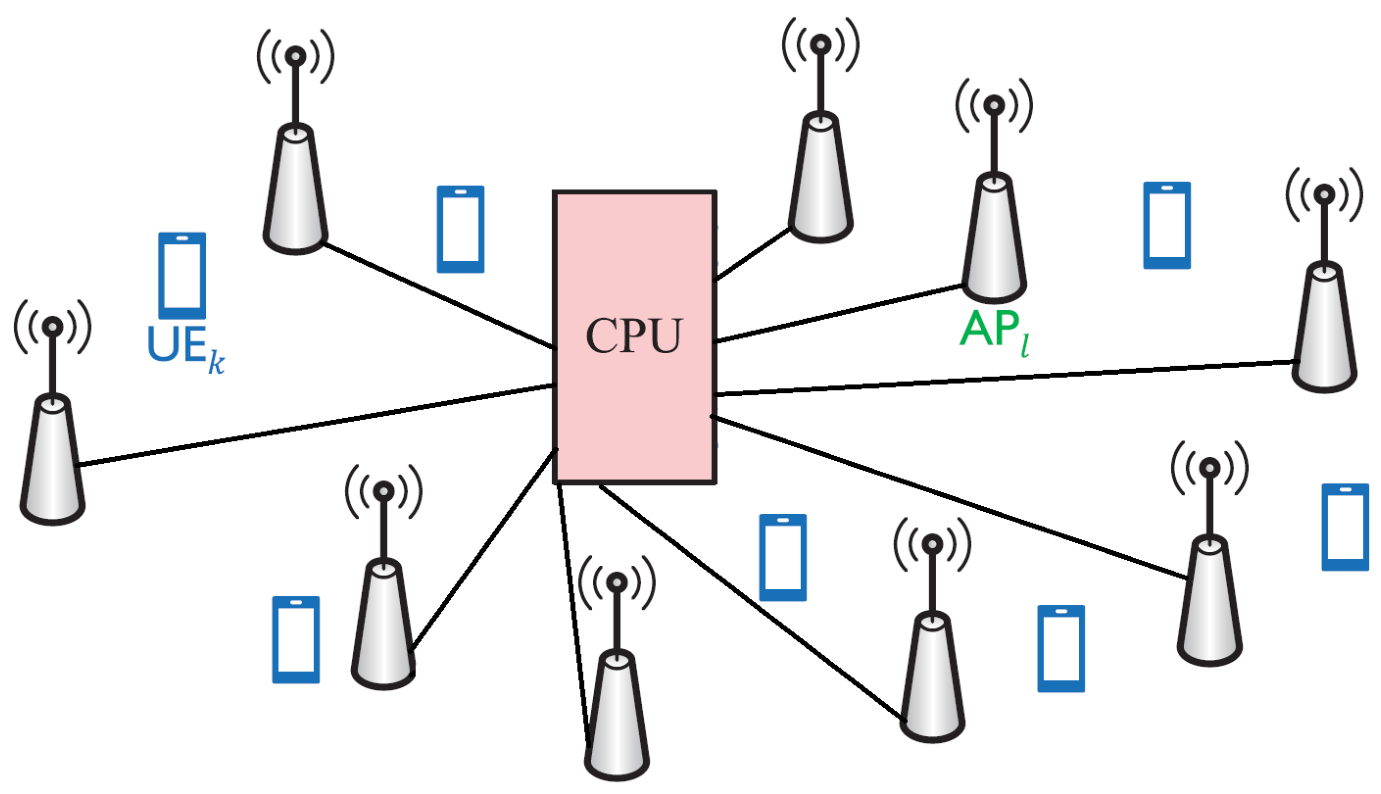
Concerning CF-M-MIMO, the network is configured with L APs, each equipped with N antennas, strategically deployed in a distributed manner across the coverage area. These APs are interconnected with CPUs through fronthaul links, facilitating the exchange of critical information such as channel state data for uplink decoding and downlink precoding. Within this framework, we analyze a CF-M-MIMO system where a multitude of single-antenna user equipment (UE) is collectively served by all available APs. Let L, N, and K represent the quantities of APs, antennas per AP, and UEs, respectively. The system operates under time-division duplexing (TDD), ensuring synchronization between base stations and users, thereby maximizing spectral efficiency and network performance. The arrangement allows for seamless interaction between distributed APs and UEs in a coordinated fashion, enhancing the overall network capacity.
For the CF-M-MIMO network depicted in Figure 1, the received signal is formulated as:
here, , while is expressed by .
Analogous to the situation outlined in Massive MIMO, a reception combining vector selected from the set , where represents the set of complex numbers, is utilized, as demonstrated in [21], to identify the signal emanating from UE k. This process results in the determination of in the following manner:
Therefore, the SINR equation for the CF-M-MIMO system can be given as follows:
where the combining vector, , is represented as:
Therefore, the achievable SE for UE k is:
2.2. Decode-and-Forward (DF) Relaying
In the DF relaying setup, the received signal model is as follows: Data from the source (S) are transmitted to the relay (R). The relay receives the data, decodes then using a decoder, and generates a new signal. This newly generated signal is then forwarded by the relay to the destination device (D). The formulation of the received signal model can be described as follows:
here, y represents the signal received by the target device (D). indicates channel conditions between source (S) and relay (R). shows the channel conditions between the relay (R) and the target device (D). represents the strength of the signal sent by the source (S). represents the strength of the signal sent by the relay (R). s represents the information signal sent from the source. n represents noise. Noise is a random process, usually with a Gaussian distribution. Since DF relaying is a technique in which the relay transmits by decoding and resending signals received from the source, the received signal model has two separate relay-sourced terms: (source-sourced) and (relay-sourced). These terms reflect the data processing and transmission process that the relay performs. As elucidated in reference [50], this characteristic is commonly observed in relay channels distinguished by the relay’s comprehensive decoding capabilities. Consequently, the upper bound of achievable speed for the relay to accurately decipher the source message is expressed as . Furthermore, the maximum achievable speed for the destination to consistently decode the source message, achieved through iterative transmissions between both the source and destination, is presented as . The stipulation mandating flawless decoding of the entire codeword by both the relay and the destination necessitates the determination of the minimum value between the two mutual information measures, as succinctly summarized in [51]. Similar to capacity expression [51] for DF relaying:
In communication with DF relay, the receiving device receives the signal sent by the relay and sends it again. In this case, signifies the intensity of the signal directly received from the source device, and denotes the intensity of the signal directly received from the source device. The expression denotes the magnitude of the signal received from the relay device. The minimum function allows the lower of these two signals to be selected. In this way, the target device receives the best signal, and its speed is optimized.
2.3. Intelligent Reflecting Surfaces
Utilizing IRS in communication systems introduces a relaying setup similar to the half-duplex mMIMO relay case. However, it distinguishes itself by allowing each element in the IRS scatterers to manipulate incoming signals through controllable phase shifts, devoid of power amplification or necessitating a distinct retransmission phase. An emerging technology that offers network operators control over radio signal propagation is IRS, commonly known as the reconfigurable intelligent surface in the current literature. These surfaces can enhance the efficiency of conventional communication systems by enabling reconfigurable propagation channels between APs and users, accomplished with minimal power requirements.
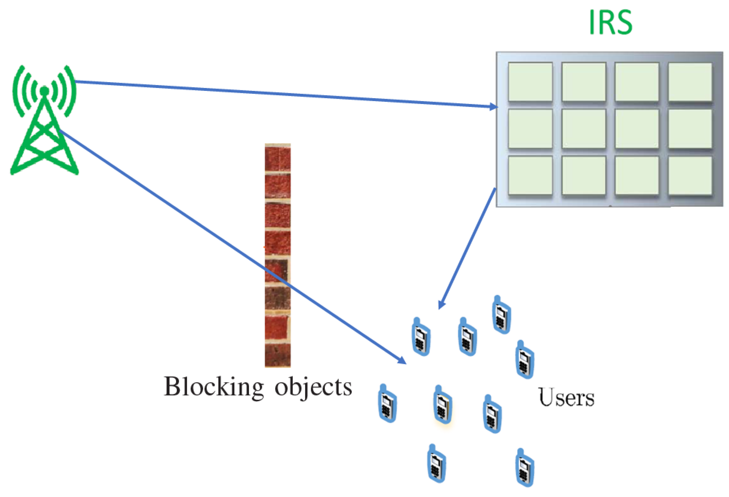
As depicted in Figure 2, the combined path from the Base Station (BS) to the user, involving each IRS element, consists of three primary elements: BS–IRS connection, the reflection by IRS, and the IRS–user connection. The behavior of this unified channel exhibits distinctive features when juxtaposed with the conventional direct channel. More precisely, each element of the IRS captures overlaid multipath signals from the transmitter, dispersing the amalgamated signal with flexible amplitude and/or phase adjustments, emulating a ’multiplicative’ channel model.
In mathematical terms, the reflected signal from the nth element, denoted as , is computed through the multiplication of the associated incident signal by a complex reflection coefficient. In other words, the expression elucidates that and define the reflection coefficient governing the amplitude and phase shift of the reflected signal, respectively. The aggregate count of reflecting elements within IRS is denoted by N. Through judicious adjustments to these reflection coefficients, IRS can exert spatial control over the reflected signal, serving diverse objectives such as optimizing user received power or accomplishing signal/interference cancellation. Nevertheless, practical considerations, encompassing factors like mutual coupling among elements, noise, and hardware imperfections, necessitate continuous research to evaluate their influence on the performance of IRS.
Equipped with a controller, the IRS is overseen as it switches between two operational modes: one for receiving, dedicated to channel estimation, and the other for reflecting, primarily focused on data transmission. Due to significant path loss, signals that undergo multiple reflections by the IRS are considered negligible and consequently disregarded. Delineating the enhancement in performance facilitated by IRS involves assuming perfect knowledge of CSI for all relevant channels associated with the AP. Considering IRS as a passive reflector, we assume the use of TDD for transmissions in both transmission of the uplink and downlink. Enabling channel reciprocity simplifies the acquisition of CSI during downlink, subject to the specifics of uplink training protocols.
The baseband equivalent channels, denoted as from the AP to IRS, along with channels from IRS to user k () and from AP to user k (), play a pivotal role in the signal transmission process. Each element of the IRS captures overlapping multipath signals, diffusing the combined signal while modifying either the amplitude or phase, as if originating from a single point source. Let be considered, and let be introduced as the matrix of reflection coefficients for the IRS. Here, denotes the phase shift, and represents the amplitude reflection coefficient for the nth element of the IRS, with ranging within and within .
In the described setup employing an IRS with N individual elements, we denote the deterministic channel from the source to the IRS as , while the channel connecting the IRS to the destination is represented as . The IRS, characterized by constant gain scattering from its elements, is succinctly described by the diagonal matrix
where stands for the fixed amplitude reflection coefficient, and are phase-shift variables optimized by the IRS. According to the model introduced in [16,52], the received signal at the destination is expressed as:
here, represents the direct channel from the source to the destination, p is the transmitted power, s is the signal, and n is the additive noise. The IRS’s channel capacity, denoted as , is formulated as [52]:
This capacity expression encapsulates the impact of the source–destination channel, the number of IRS elements , and the IRS’s reflection characteristics. Assuming perfect channel knowledge, the achievable Spectral Efficiency (SE) is given by:
where is represented as:
These expressions collectively capture the signal propagation, channel characteristics, and the impact of the IRS on the communication system.
2.4. Problem Definition
The main objective of this study is to investigate a proposed new method-aided wireless communication system based on IRS and compare it with DF relaying and CF-M-MIMO architectures. Analyses were carried out to evaluate how much gain the systems provide in terms of required transmission power for a specific achievable rate, energy, and spectrum efficiency according to the number of elements/antennas.
3. Proposed ORS Method with IRS
The signal received in the system model proposed as the IRS-based ORS method is as follows:
here, y represents the received signal at the target. indicates the deterministic flat fade channel between source and target. This is equivalent to the source-to-destination (S-D) channel gain, . p refers to the strength of the signal sent by the transmitter. is the reflection coefficient of the IRS. represents source–IRS channel gain. represents the IRS–target channel gain. n represents noise, and s is the unit-power information signal.
The capacity expression for ORS-IRS is expressed as follows, based on the study in [52];
here, represents the total achievable rate. Other variables and symbols are as follows: p, transmitter power; , source–IRS channel gain; , IRS–target channel gain; , source–target channel gain; , reflection coefficient; and , noise strength.
ORS-IRS represents an innovative approach that harnesses intelligent reflecting surfaces to enhance communication performance, positioning it as a promising technique for addressing the escalating demands of wireless communication networks. Ongoing research in this domain aims to further refine and optimize the algorithm’s capabilities for various communication scenarios and deployment environments.
In the context of this study, the central focus is on achieving the maximum desired capacity in the realm of performance comparison. Specifically, the direct exploration of relay selection has not been the primary concern, and detailed analyses on this topic have been referred to in existing studies in the literature [53,54]. The fundamental aim of this study is the maximization of capacity in communication systems. In pursuit of this goal, and considering the insights from relay selection studies in the literature, the emphasis has been placed on reaching the pinnacle of capacity. The ORS-IRS algorithm aligns with this overarching objective by optimizing the positions and reflection coefficients of intelligent reflecting surfaces. This optimization process employs mathematical programming or optimization algorithms, facilitating a systematic exploration of the solution space and the identification of configurations that offer the highest achievable performance. For a comprehensive understanding, the procedural intricacies of the proposed ORS-IRS method are meticulously outlined in Algorithm 1.
ORS-IRS provides several advantages in wireless communication systems, including:
- Enhanced Signal Power: ORS-IRS boosts signal power by reflecting electromagnetic waves, resulting in a stronger and more reliable communication channel.
- Improved Multipath Propagation: ORS-IRS governs multipath propagation, mitigating the interference of delayed signals with noise and thereby enhancing communication quality.
- Increased Channel Capacity: ORS-IRS can augment the communication channel’s capacity, facilitating higher data rates and accommodating more users simultaneously.
These advantages contribute to the overall enhancement and efficiency of wireless communication systems.
| Algorithm 1 ORS-IRS Algorithm. |
Require: p, , , , , , N.
|
The proposed method can be expressed as follows: The ORS-IRS algorithm aims to optimize communication performance in wireless systems by maximizing the Signal-to-Interference-plus-Noise Ratio (SINR) metric. SINR represents the ratio of signal power in the communication channel to the aggregate power of interference and noise at the receiver. This algorithm concentrates on IRS, intending to optimize the locations and reflection coefficients of these surfaces to maximize SINR values. Consequently, it facilitates the establishment of more robust and reliable communication channels, mitigates the impact of multipath propagation, and enhances communication capacity. The ultimate objective is to maximize achievable data rates for users.
denotes the power level of the signal transmitted by the source (transmitter) and perceived by the receiver. denotes the noise power, indicating the level of noise present in the environment. N represents the number of IRS elements or collectors. represents the channel gain of the n-th element, indicating the power of the channel between the transmitter and the n-th element. represents the channel gain of the n-th element, indicating the power of the channel between the n-th element and the destination (receiver).
The equation is used to calculate the SNR of the ORS-IRS receiver. Each element’s channel gain is multiplied by the term , and these values are then summed. The result is subsequently multiplied by Ptx and divided by . Finally, the obtained value is squared to calculate the . This equation is utilized to assess the performance of the ORS-IRS receiver and analyze the impact of different parameters (such as power, channel gains, number of elements, etc.) on the signal-to-noise ratio. Signal latency reduction in the ORS-IRS algorithm can be mathematically justified through the optimization of key parameters influencing latency, primarily focusing on achieving higher SNR and enhancing the achievable data rate. The channel gain between the source and IRS (), IRS and destination (), and source and destination () are crucial factors.The total channel gain with IRS reflection coefficients () is expressed as:
Higher () implies an improved channel gain, contributing to reduced latency. Furthermore, maximizing the in Equation (14) results in reduced latency. In summary, the ORS-IRS algorithm reduces signal latency by intelligently optimizing channel gains, leveraging the capabilities of IRS elements, dynamically adapting to changing conditions, and maximizing achievable data rates. These strategies collectively contribute to a more responsive and low-latency wireless communication system.
The ORS-IRS method, while exhibiting promising advantages, is not without limitations. One significant limitation is the sensitivity to the accuracy of CSI. The effectiveness of the algorithm relies on precise knowledge of channel gains and propagation characteristics, which may be challenging to obtain in dynamic and complex wireless environments. Moreover, the practical implementation of IRS introduces hardware and deployment constraints, especially in scenarios with mobility or varying communication conditions. Furthermore, the ORS-IRS method’s performance could be influenced by factors such as interference from other wireless systems, signal blockage, and the presence of obstacles. These external factors may impact the reliability and robustness of the proposed algorithm in real-world scenarios. It is essential to acknowledge that the effectiveness of the ORS-IRS method is context-dependent, and its performance may vary under different communication environments. While the algorithm presents a valuable contribution, researchers and practitioners should consider these limitations when applying ORS-IRS in diverse wireless communication scenarios.
4. Numerical Performance Comparison
In this numerical comparison, we consider the conditions specified by the 3rd Generation Partnership Project (3GPP) [55]. Through the utilization of this model, our objective is to assess and compare system performance under realistic propagation conditions, factoring in the influence of antenna gains and channel characteristics on overall communication quality.
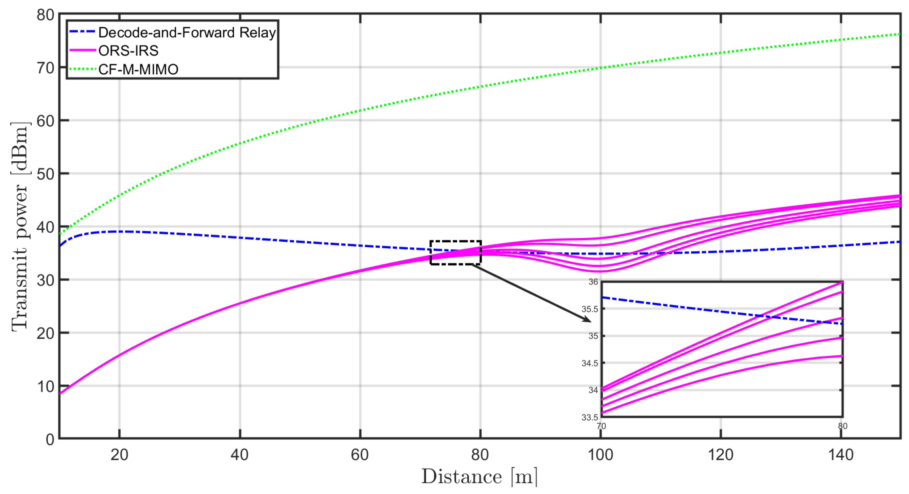
Figure 3 illustrates a comparison of the required transmit power to achieve target rates of R = 10 bit/s/Hz. The results are presented for three scenarios: CF-M-MIMO, DF relaying, and the proposed method ORS-IRS. The five different lines shown for ORS-IRS were created from top to bottom for N values of 100, 200, 500, 750, and 1000, respectively. Until a distance of approximately 76 m, the ORS-IRS scheme exhibits the lowest power requirement, while the CF-M-MIMO system necessitates the highest power at all locations. As the distance increases towards around 110 m, fluctuations in the required power are observed for the ORS-IRS scheme. However, beyond 110 m, the required power in the ORS-IRS scheme starts to increase. In contrast, the DF relaying scenario maintains stability throughout. The increase in the required power for ORS-IRS can be attributed to encountering higher Signal-to-Interference-plus-Noise Ratio (SINR) levels. In the ORS-IRS system, higher SINR conditions lead to an increase in the required power. The comparison reveals that IRS and DF relaying outperform the CF-M-MIMO case, with IRS becoming more competitive at higher rates, requiring minimum power consumption when the destination is in close proximity to the source and needing fewer elements to surpass the performance of relaying.
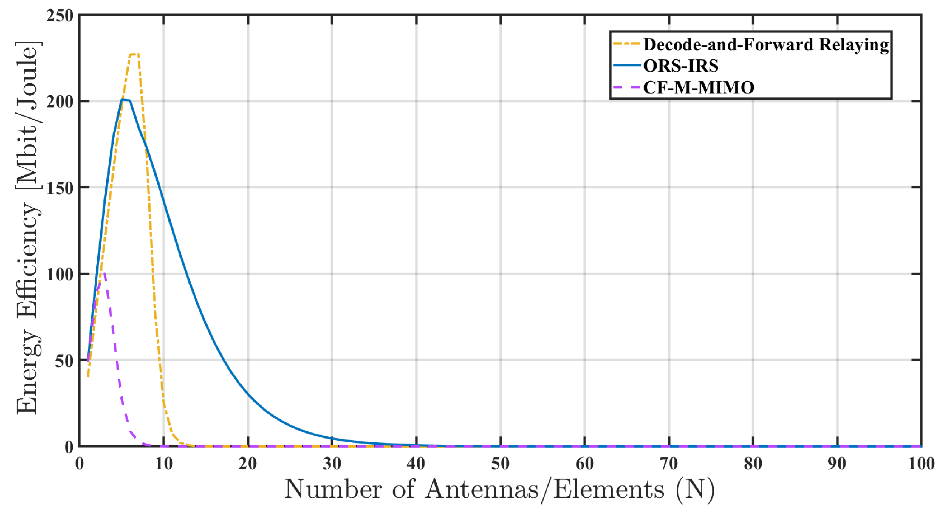
Within the realm of wireless communication systems, a study conducted in [56] has demonstrated that the incorporation of Intelligent Reflecting Surfaces (IRS) can significantly enhance energy efficiency. Drawing on this insight, the comparison of the proposed ORS-IRS method with CF-M-MIMO and DF relaying in terms of energy efficiency is depicted in Figure 4. While efficiency at N = 3 yields similar results in all three cases, both ORS-IRS and DF relaying exhibit similar increasing trends at values of N between 3 and 5. With the subsequent declines, it becomes evident that ORS-IRS saturates at larger values of N. The sustained energy efficiency after a certain value of N can be attributed to the transmission system reaching a specific capacity or limit. Beyond this point, the addition of more antennas or elements may have a limited or negligible impact on energy efficiency. In the design of transmission systems, particularly in wireless communication systems, an initial increase in energy efficiency is often achievable with a greater number of antennas or elements. This augmentation provides enhanced capacity or diversity. However, the advantages of integrating extra antennas or elements begin to diminish after reaching a certain threshold.
The reasons for this fixation can be:
- Channel Capacity Limitations: After a point, adding more antennas or items may keep the overall transmission rate at a certain level due to channel capacity limitations. Channel capacity may reach saturation at a certain point, meaning that additional capacity increases do not improve energy efficiency.
- Mismatch: As you add more antennas or items, you may need more processing power and resources to optimize the system. If these extra resources are associated with energy consumption, the increase in energy efficiency may be limited.
- Proximity Effect: Antennas or items that are too close together can be limiting factors at some point due to enhanced multiple paths and interference. Therefore, adding additional antennas or elements may have a limited effect on energy efficiency.
- Fading Effects: Multipath effects can increase excessive noise or fading effects with the addition of additional antennas or elements, which can have a negative impact on energy efficiency.
- Frame Limitations: Within the framework of a particular application or protocol, the transmission system may be limited to a certain number of antennas or elements. Therefore, adding more antennas or elements after a certain point may have limited impact on energy efficiency.
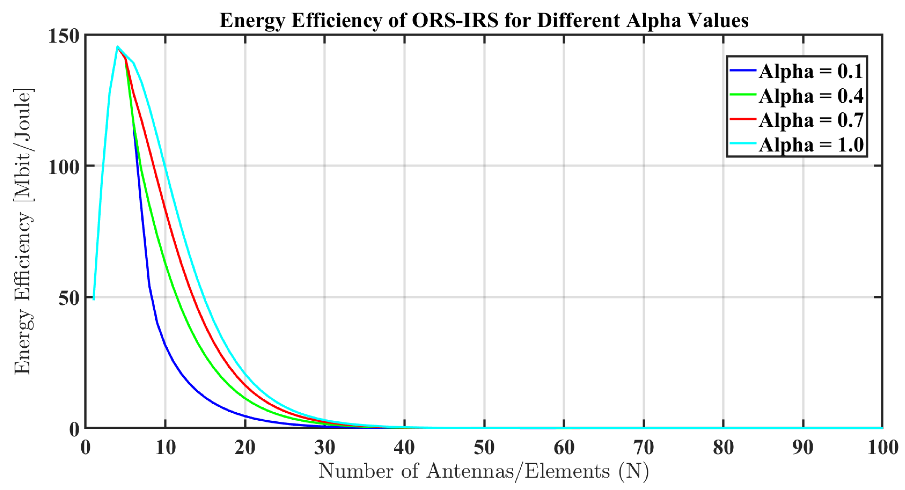
Figure 5 illustrates the energy efficiency values at different alpha values for ORS-IRS. In this context, the alpha value signifies the extent to which reflective elements are employed in the ORS-IRS configuration. ORS-IRS comprises surfaces capable of directing and reflecting electromagnetic waves. The alpha value specifies the reflectance coefficient of the reflective elements, offering insights into the impact of ORS-IRS on signal orientation.
Conducting experiments with various alpha values allows us to comprehend the influence of ORS-IRS on its performance and energy efficiency. A higher alpha value implies that reflective elements more forcefully direct and reflect signals. Although this can enhance capacity and coverage in specific communication scenarios, it may also lead to increased power consumption. Conversely, a lower alpha value indicates less effectiveness of reflective elements, potentially offering an advantage in terms of energy efficiency. Consequently, determining the optimal combination of alpha values becomes crucial for optimizing the performance of ORS-IRS.
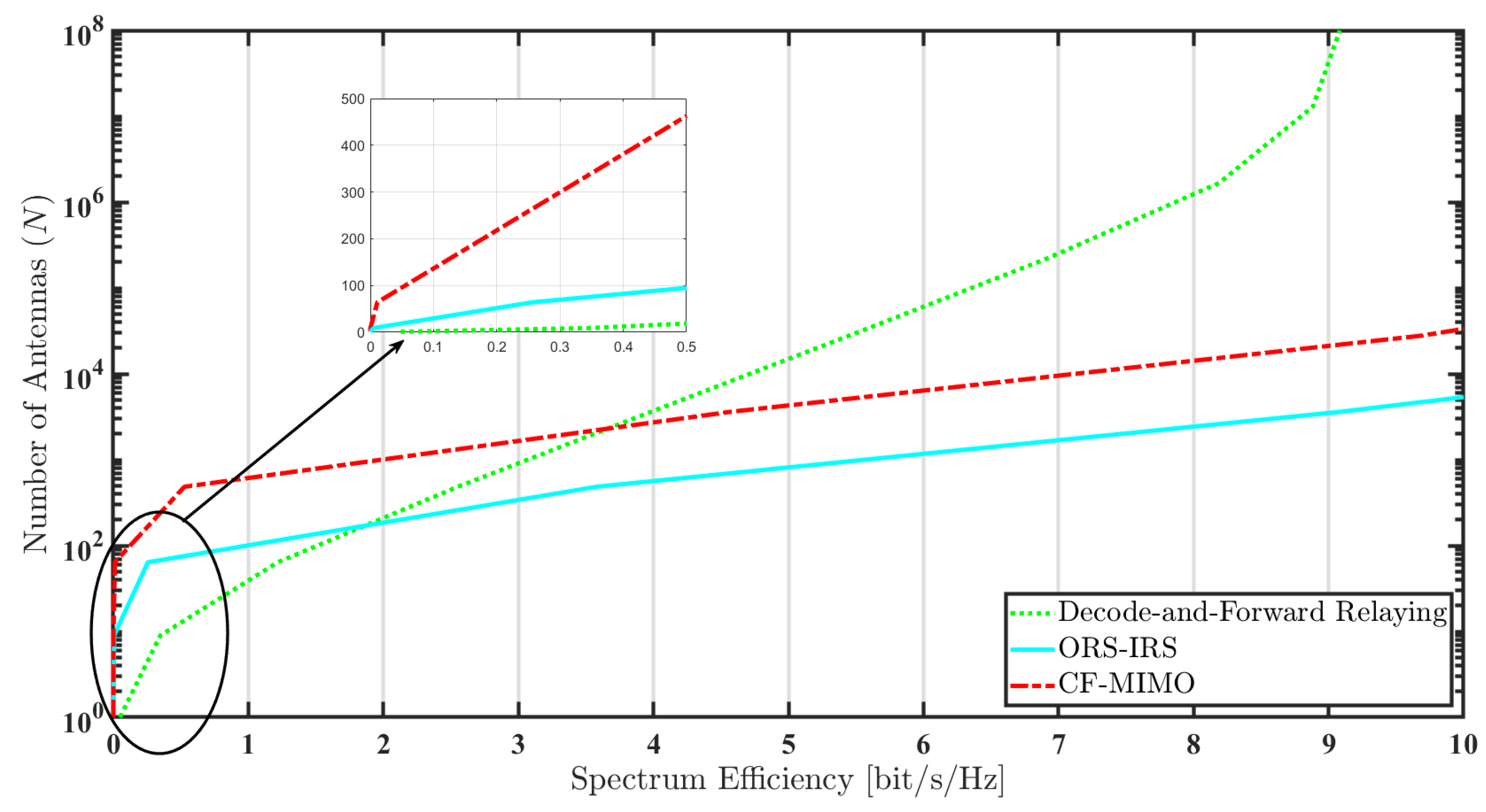
Figure 6 illustrates the antenna requirements for all three methodologies to achieve a specific spectrum efficiency. Upon initial analysis of the graphical outcomes, it becomes evident that, for a spectrum efficiency above zero, the CF-M-MIMO system necessitates an approximate sevenfold increase in the number of antennas compared to the ORS-IRS configuration. Notably, DF relaying exhibits the lowest minimal antenna requirement. Post this threshold, no sharp spikes in antenna requirements are observed. For spectrum efficiencies exceeding approximately 3.5 bit/s/Hz, the DF relaying scheme continues to demand an escalation in antenna count. However, both CF-M-MIMO and ORS-IRS approaches manifest a trend moving closer to horizontal. In the scenario involving 3600 antennas, CF-M-MIMO and DF relaying showcase comparable spectrum efficiencies, albeit slightly superior. In contrast, the spectrum efficiency for ORS-IRS surpasses that of the others by a factor of about 2–3.
5. Conclusions, Discussion, and Future Work
This study culminated in a comprehensive exploration of three advanced wireless communication methodologies: ORS-IRS, CF-M-MIMO, and the DF relaying approach. The ORS-IRS strategy demonstrated innovation by seamlessly integrating IRS with relay selection techniques, resulting in heightened signal strength and diminished latency. Conversely, CF-M-MIMO exhibited efficacy in accommodating a larger user base, leading to substantial capacity gains. Simultaneously, the DF relaying approach played a unique role in enhancing signal reliability over extended distances.
In the ensuing discussion, we elucidated the distinctive advantages of each strategy. ORS-IRS excelled in optimizing channel capacity and transmission power for reliable, low-latency data transmission. CF-M-MIMO adeptly delivered high capacity to multiple users concurrently, while the DF approach showcased potential in enhancing reliability over extended distances.
Looking ahead to future research, the exploration of hybrid methodologies amalgamating the strengths of ORS-IRS, CF-M-MIMO, and DF relaying was suggested. Such hybrid schemes could synergistically combine high-capacity provisioning and enhanced reliability, harnessing the collective benefits of these distinct methodologies. Furthermore, we proposed investigating dynamic resource allocation strategies that adapt to real-time traffic patterns and user demands. Optimization of energy efficiency, effective interference management in multi-user environments, and practical implementations on real-world testbeds were identified as pivotal areas for future research. Lastly, we emphasized the consideration of security and privacy measures to safeguard sensitive information in an era of heightened connectivity. These future research directions aim to deepen our understanding of advanced communication paradigms and facilitate the development of communication systems with heightened capacity, reliability, and security.
Funding
This research received no external funding.
Data Availability Statement
Data are contained within the article.
Conflicts of Interest
The author declares no conflicts of interest.
References
- Zhang, M.; Zhuang, Z.; Kim, S. IRS-Assisted Hybrid Secret Key Generation. Symmetry 2023, 15, 1906. [Google Scholar] [CrossRef]
- Lin, W.Y.; Chang, T.H.; Tseng, S.M. Deep Learning-Based Cross-Layer Power Allocation for Downlink Cell-Free Massive Multiple-Input-Multiple-Output Video Communication Systems. Symmetry 2023, 15, 1968. [Google Scholar] [CrossRef]
- Kumar, P.; Dhaka, K. Performance of Wireless Powered DF Relay System Under Nakagami-m Fading: Relay Assists Energy-Constrained Source. IEEE Syst. J. 2020, 14, 2497–2507. [Google Scholar] [CrossRef]
- Ren, S.; Shen, K.; Zhang, Y.; Li, X.; Chen, X.; Luo, Z.Q. Configuring Intelligent Reflecting Surface With Performance Guarantees: Blind Beamforming. IEEE Trans. Wirel. Commun. 2023, 22, 3355–3370. [Google Scholar] [CrossRef]
- Wang, W.; Zhang, W. Joint Beam Training and Positioning for Intelligent Reflecting Surfaces Assisted Millimeter Wave Communications. IEEE Trans. Wirel. Commun. 2021, 20, 6282–6297. [Google Scholar] [CrossRef]
- Abeywickrama, S.; Zhang, R.; Wu, Q.; Yuen, C. Intelligent Reflecting Surface: Practical Phase Shift Model and Beamforming Optimization. IEEE Trans. Commun. 2020, 68, 5849–5863. [Google Scholar] [CrossRef]
- Wang, W.; Zhang, W. Intelligent Reflecting Surface Configurations for Smart Radio Using Deep Reinforcement Learning. IEEE J. Sel. Areas Commun. 2022, 40, 2335–2346. [Google Scholar] [CrossRef]
- Ma, Q.; Gao, W.; Xiao, Q.; Ding, L.; Gao, T.; Zhou, Y.; Gao, X.; Yan, T.; Liu, C.; Gu, Z.; et al. Directly wireless communication of human minds via non-invasive brain-computer-metasurface platform. eLight 2022, 2, 11. [Google Scholar] [CrossRef]
- Chen, L.; Ma, Q.; Luo, S.S.; Ye, F.; Cui, H.; Cui, T. Touch-Programmable Metasurface for Various Electromagnetic Manipulations and Encryptions. Small 2022, 18, 2203871. [Google Scholar] [CrossRef]
- Sejan, M.A.S.; Rahman, M.H.; Shin, B.S.; Oh, J.H.; You, Y.H.; Song, H.K. Machine Learning for Intelligent-Reflecting-Surface-Based Wireless Communication towards 6G: A Review. Sensors 2022, 22, 5405. [Google Scholar] [CrossRef]
- Wang, Z.; Liu, L.; Cui, S. Channel Estimation for Intelligent Reflecting Surface Assisted Multiuser Communications: Framework, Algorithms, and Analysis. IEEE Trans. Wirel. Commun. 2020, 19, 6607–6620. [Google Scholar] [CrossRef]
- He, Z.Q.; Yuan, X. Cascaded Channel Estimation for Large Intelligent Metasurface Assisted Massive MIMO. IEEE Wirel. Commun. Lett. 2020, 9, 210–214. [Google Scholar] [CrossRef]
- Wang, P.; Fang, J.; Duan, H.; Li, H. Compressed Channel Estimation for Intelligent Reflecting Surface-Assisted Millimeter Wave Systems. IEEE Signal Process. Lett. 2020, 27, 905–909. [Google Scholar] [CrossRef]
- Zhang, W.; Xu, J.; Xu, W.; Ng, D.W.K.; Sun, H. Cascaded Channel Estimation for IRS-Assisted mmWave Multi-Antenna With Quantized Beamforming. IEEE Commun. Lett. 2021, 25, 593–597. [Google Scholar] [CrossRef]
- Song, Y.; Khandaker, M.R.A.; Tariq, F.; Wong, K.K.; Toding, A. Truly Intelligent Reflecting Surface-Aided Secure Communication Using Deep Learning. In Proceedings of the 2021 IEEE 93rd Vehicular Technology Conference (VTC2021-Spring), Virtual, 25–28 April 2021; pp. 1–6. [Google Scholar] [CrossRef]
- Ozdogan, O.; Björnson, E.; Larsson, E.G. Intelligent Reflecting Surfaces: Physics, Propagation, and Pathloss Modeling. IEEE Wirel. Commun. Lett. 2020, 9, 581–585. [Google Scholar] [CrossRef]
- Yu, X.; Xu, D.; Schober, R. Optimal Beamforming for MISO Communications via Intelligent Reflecting Surfaces. In Proceedings of the 2020 IEEE 21st International Workshop on Signal Processing Advances in Wireless Communications (SPAWC), Atlanta, GA, USA, 26–29 May 2020; pp. 1–5. [Google Scholar] [CrossRef]
- Han, Y.; Tang, W.; Jin, S.; Wen, C.K.; Ma, X. Large Intelligent Surface-Assisted Wireless Communication Exploiting Statistical CSI. IEEE Trans. Veh. Technol. 2019, 68, 8238–8242. [Google Scholar] [CrossRef]
- Zhang, J.; Björnson, E.; Matthaiou, M.; Ng, D.W.K.; Yang, H.; Love, D.J. Prospective Multiple Antenna Technologies for Beyond 5G. IEEE J. Sel. Areas Commun. 2020, 38, 1637–1660. [Google Scholar] [CrossRef]
- Chakraborty, S.; Demir, O.T.; Björnson, E.; Giselsson, P. Efficient Downlink Power Allocation Algorithms for Cell-Free Massive MIMO Systems. IEEE Open J. Commun. Soc. 2021, 2, 168–186. [Google Scholar] [CrossRef]
- Demir, O.T.; Björnson, E.; Sanguinetti, L. Foundations of User-Centric Cell-Free Massive MIMO. Now Found. Trends Signal Process. 2021, 14, 162–472. [Google Scholar] [CrossRef]
- Björnson, E.; Sanguinetti, L. Scalable Cell-Free Massive MIMO Systems. IEEE Trans. Commun. 2020, 68, 4247–4261. [Google Scholar] [CrossRef]
- Björnson, E.; Sanguinetti, L. Making Cell-Free Massive MIMO Competitive With MMSE Processing and Centralized Implementation. IEEE Trans. Wirel. Commun. 2020, 19, 77–90. [Google Scholar] [CrossRef]
- Zheng, J.; Zhang, J.; Björnson, E.; Ai, B. Impact of Channel Aging on Cell-Free Massive MIMO Over Spatially Correlated Channels. IEEE Trans. Wirel. Commun. 2021, 20, 6451–6466. [Google Scholar] [CrossRef]
- Zheng, J.; Zhang, J.; Ai, B. UAV Communications With WPT-Aided Cell-Free Massive MIMO Systems. IEEE J. Sel. Areas Commun. 2021, 39, 3114–3128. [Google Scholar] [CrossRef]
- Shi, E.; Zhang, J.; Chen, S.; Zheng, J.; Zhang, Y.; Kwan Ng, D.W.; Ai, B. Wireless Energy Transfer in RIS-Aided Cell-Free Massive MIMO Systems: Opportunities and Challenges. IEEE Commun. Mag. 2022, 60, 26–32. [Google Scholar] [CrossRef]
- Demir, O.T.; Björnson, E. Joint Power Control and LSFD for Wireless-Powered Cell-Free Massive MIMO. IEEE Trans. Wirel. Commun. 2021, 20, 1756–1769. [Google Scholar] [CrossRef]
- Guo, M.; Gursoy, M.C. Joint Activity Detection and Channel Estimation in Cell-Free Massive MIMO Networks With Massive Connectivity. IEEE Trans. Commun. 2022, 70, 317–331. [Google Scholar] [CrossRef]
- Van Chien, T.; Björnson, E.; Larsson, E.G. Joint Power Allocation and Load Balancing Optimization for Energy-Efficient Cell-Free Massive MIMO Networks. IEEE Trans. Wirel. Commun. 2020, 19, 6798–6812. [Google Scholar] [CrossRef]
- Guo, F.; Lu, H.; Gu, Z. Joint Power and User Grouping Optimization in Cell-Free Massive MIMO Systems. IEEE Trans. Wirel. Commun. 2022, 21, 991–1006. [Google Scholar] [CrossRef]
- Guenach, M.; Gorji, A.A.; Bourdoux, A. Joint Power Control and Access Point Scheduling in Fronthaul-Constrained Uplink Cell-Free Massive MIMO Systems. IEEE Trans. Commun. 2021, 69, 2709–2722. [Google Scholar] [CrossRef]
- Buzzi, S.; D’Andrea, C.; Zappone, A.; D’Elia, C. User-Centric 5G Cellular Networks: Resource Allocation and Comparison With the Cell-Free Massive MIMO Approach. IEEE Trans. Wirel. Commun. 2020, 19, 1250–1264. [Google Scholar] [CrossRef]
- Masoumi, H.; Emadi, M.J. Performance Analysis of Cell-Free Massive MIMO System With Limited Fronthaul Capacity and Hardware Impairments. IEEE Trans. Wirel. Commun. 2020, 19, 1038–1053. [Google Scholar] [CrossRef]
- Bashar, M.; Akbari, A.; Cumanan, K.; Ngo, H.Q.; Burr, A.G.; Xiao, P.; Debbah, M.; Kittler, J. Exploiting Deep Learning in Limited-Fronthaul Cell-Free Massive MIMO Uplink. IEEE J. Sel. Areas Commun. 2020, 38, 1678–1697. [Google Scholar] [CrossRef]
- Femenias, G.; Riera-Palou, F. Fronthaul-Constrained Cell-Free Massive MIMO With Low Resolution ADCs. IEEE Access 2020, 8, 116195–116215. [Google Scholar] [CrossRef]
- Zhao, Y.; Niemegeers, I.G.; De Groot, S.H. Power Allocation in Cell-Free Massive MIMO: A Deep Learning Method. IEEE Access 2020, 8, 87185–87200. [Google Scholar] [CrossRef]
- Souryal, M.; Vojcic, B. Performance of Amplify-and-Forward and Decode-and-Forward Relaying in Rayleigh Fading with Turbo Codes. In Proceedings of the 2006 IEEE International Conference on Acoustics Speech and Signal Processing Proceedings, Toulouse, France, 14–19 May 2006; Volume 4, p. IV. [Google Scholar] [CrossRef]
- Levin, G.; Loyka, S.L. Amplify-and-forward versus decode-and-forward relaying: Which is better? In Proceedings of the 22th International Zurich Seminar on Communications (IZS), Zurich, Switzerland, 29 February–2 March 2012. [Google Scholar] [CrossRef]
- Woradit, K. Decode-and-Forward Relaying Protocol with Optimal Degrees of Freedom for Proactively Selective Wireless Relay Networks. In Proceedings of the 2019 Research, Invention, and Innovation Congress (RI2C), Bangkok, Thailand, 11–13 December 2019; pp. 1–6. [Google Scholar] [CrossRef]
- Khormuji, M.N.; Larsson, E.G. Cooperative transmission based on decode-and-forward relaying with partial repetition coding. IEEE Trans. Wirel. Commun. 2009, 8, 1716–1725. [Google Scholar] [CrossRef]
- Chaoudhry, B.; Hassan, S.; Speidel, J.; Jung, H. Energy Efficiency of a Decode-and-Forward Multiple-Relay Network with Rate Adaptive LDPC Codes. Sensors 2019, 19, 4793. [Google Scholar] [CrossRef] [PubMed]
- Çağan, A.T.; Koç, G.B.; Yakın, H.; Çiloğlu, B.; Ashgar, M.Z.; Özgün, E.; Hämäläinen, J.; Öztürk, M. UAV-based Maritime Communications: Relaying to Enhance the Link Quality. arXiv 2023, arXiv:2304.08650. [arXiv:cs.NI/2304.08650]. [Google Scholar]
- Moon, J. Performance Comparison of Relay-Based Covert Communications: DF, CF and AF. Sensors 2023, 23, 8747. [Google Scholar] [CrossRef]
- Hu, H.; Xu, K.; Xie, W.; Xia, X.; Wang, M. Multi-Intelligent Reflecting Surface Assisted Cell-free Massive MIMO Downlink Transmission. In Proceedings of the 2021 IEEE 21st International Conference on Communication Technology (ICCT), Tianjin, China, 13–16 October 2021; pp. 531–537. [Google Scholar] [CrossRef]
- Zhou, T.; Xu, K.; Xie, W.; Shen, Z.; Wei, C.; Liu, J.; Sun, L. Aerial intelligent reflecting surface-enhanced cell-free massive MIMO for high-mobility communication: Joint Doppler compensation and power optimization. EURASIP J. Adv. Signal Process. 2021, 2021, 68. [Google Scholar] [CrossRef]
- Zhou, T.; Xu, K.; Xia, X.; Xie, W.; Xu, J. Achievable Rate Optimization for Aerial Intelligent Reflecting Surface-Aided Cell-Free Massive MIMO System. IEEE Access 2021, 9, 3828–3837. [Google Scholar] [CrossRef]
- Huang, R.; Wong, V.W. Towards Reliable Communications in Intelligent Reflecting Surface-Aided Cell-Free MIMO Systems. In Proceedings of the 2021 IEEE Global Communications Conference (GLOBECOM), Madrid, Spain, 7–11 December 2021; pp. 1–6. [Google Scholar] [CrossRef]
- Huang, S.; Ye, Y.; Xiao, M.; Poor, H.V.; Skoglund, M. Decentralized Beamforming Design for Intelligent Reflecting Surface-Enhanced Cell-Free Networks. IEEE Wirel. Commun. Lett. 2021, 10, 673–677. [Google Scholar] [CrossRef]
- Noh, T.; Choi, J. Cell-Free MIMO Systems Powered by Intelligent Reflecting Surfaces. IEEE Commun. Lett. 2022, 26, 1076–1080. [Google Scholar] [CrossRef]
- Cover, T.; Gamal, A. Capacity theorems for the relay channel. IEEE Trans. Inf. Theory 1979, 25, 572–584. [Google Scholar] [CrossRef]
- Laneman, J.; Tse, D.; Wornell, G. Cooperative diversity in wireless networks: Efficient protocols and outage behavior. IEEE Trans. Inf. Theory 2004, 50, 3062–3080. [Google Scholar] [CrossRef]
- Björnson, E.; Ozdogan, O.; Larsson, E.G. Intelligent Reflecting Surface Versus Decode-and-Forward: How Large Surfaces are Needed to Beat Relaying? IEEE Wirel. Commun. Lett. 2020, 9, 244–248. [Google Scholar] [CrossRef]
- Mahama, S.; Asiedu, D.K.P.; Lee, K.J. Simultaneous Wireless Information and Power Transfer for Cooperative Relay Networks with Battery. IEEE Access 2017, 5, 13171–13178. [Google Scholar] [CrossRef]
- Huang, C.; Chen, G.; Gong, Y.; Wen, M.; Chambers, J.A. Deep Reinforcement Learning-Based Relay Selection in Intelligent Reflecting Surface Assisted Cooperative Networks. IEEE Wirel. Commun. Lett. 2021, 10, 1036–1040. [Google Scholar] [CrossRef]
- 3GPP. Evolved Universal Terrestrial Radio Access (E-UTRA); Radio Resource Control (RRC); Protocol specification. Technical Specification (TS) 36.331, 3rd Generation Partnership Project (3GPP), 2017. Version 14.2.2. ETSI: France, 2017. Available online: https://www.etsi.org/deliver/etsi_ts/136300_136399/136331/14.02.02_60/ts_136331v140202p.pdf (accessed on 8 February 2024).
- Huang, C.; Zappone, A.; Alexandropoulos, G.C.; Debbah, M.; Yuen, C. Reconfigurable Intelligent Surfaces for Energy Efficiency in Wireless Communication. IEEE Trans. Wirel. Commun. 2019, 18, 4157–4170. [Google Scholar] [CrossRef]
Figure 1.
A cell-free massive MIMO system.

Figure 2.
IRS-aided wireless networks.

Figure 3.
Comparison of algorithms’ transmit power of the distance.

Figure 4.
Energy efficiency in terms of the quantity of elements/antennas.

Figure 5.
Energy efficiency of IRS for different alpha values.

Figure 6.
Spectrum efficiency with number of elements/antennas.

Disclaimer/Publisher’s Note: The statements, opinions and data contained in all publications are solely those of the individual author(s) and contributor(s) and not of MDPI and/or the editor(s). MDPI and/or the editor(s) disclaim responsibility for any injury to people or property resulting from any ideas, methods, instructions or products referred to in the content. |
© 2024 by the author. Licensee MDPI, Basel, Switzerland. This article is an open access article distributed under the terms and conditions of the Creative Commons Attribution (CC BY) license (https://creativecommons.org/licenses/by/4.0/).
Share and Cite
MDPI and ACS Style
Dikmen, O. Performance Analysis and Simulation of IRS-Aided Wireless Networks Communication. Symmetry 2024, 16, 254. https://doi.org/10.3390/sym16020254
AMA Style
Dikmen O. Performance Analysis and Simulation of IRS-Aided Wireless Networks Communication. Symmetry. 2024; 16(2):254. https://doi.org/10.3390/sym16020254
Chicago/Turabian StyleDikmen, Osman. 2024. "Performance Analysis and Simulation of IRS-Aided Wireless Networks Communication" Symmetry 16, no. 2: 254. https://doi.org/10.3390/sym16020254
Note that from the first issue of 2016, this journal uses article numbers instead of page numbers. See further details here.