


Effects of KoBo-Processing and Subsequent Annealing Treatment on Grain Boundary Network and Texture Development in Laser Powder Bed Fusion (LPBF) AlSi10Mg Alloy


Abstract
:1. Introduction
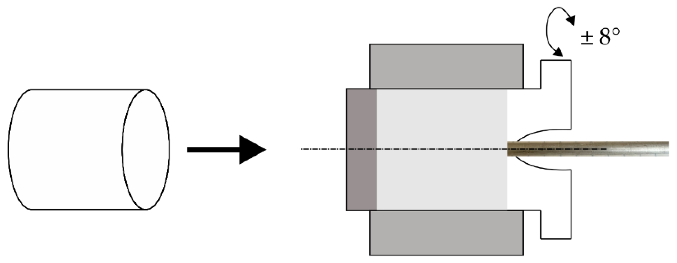
2. Methodology
- punch speed of 0.2 mm/s;
- die rotation frequency of 5 Hz;
- maximal measured temperature close to the extrusion die (~280 °C);
- sample cooling with room-temperature water.
3. Results and Discussion
4. Conclusions
- KoBo extrusion caused a significant grain refinement of LPBF AlSi10Mg alloy, resulting in a fine-grained microstructure with an average grain size of about 0.8 µm.
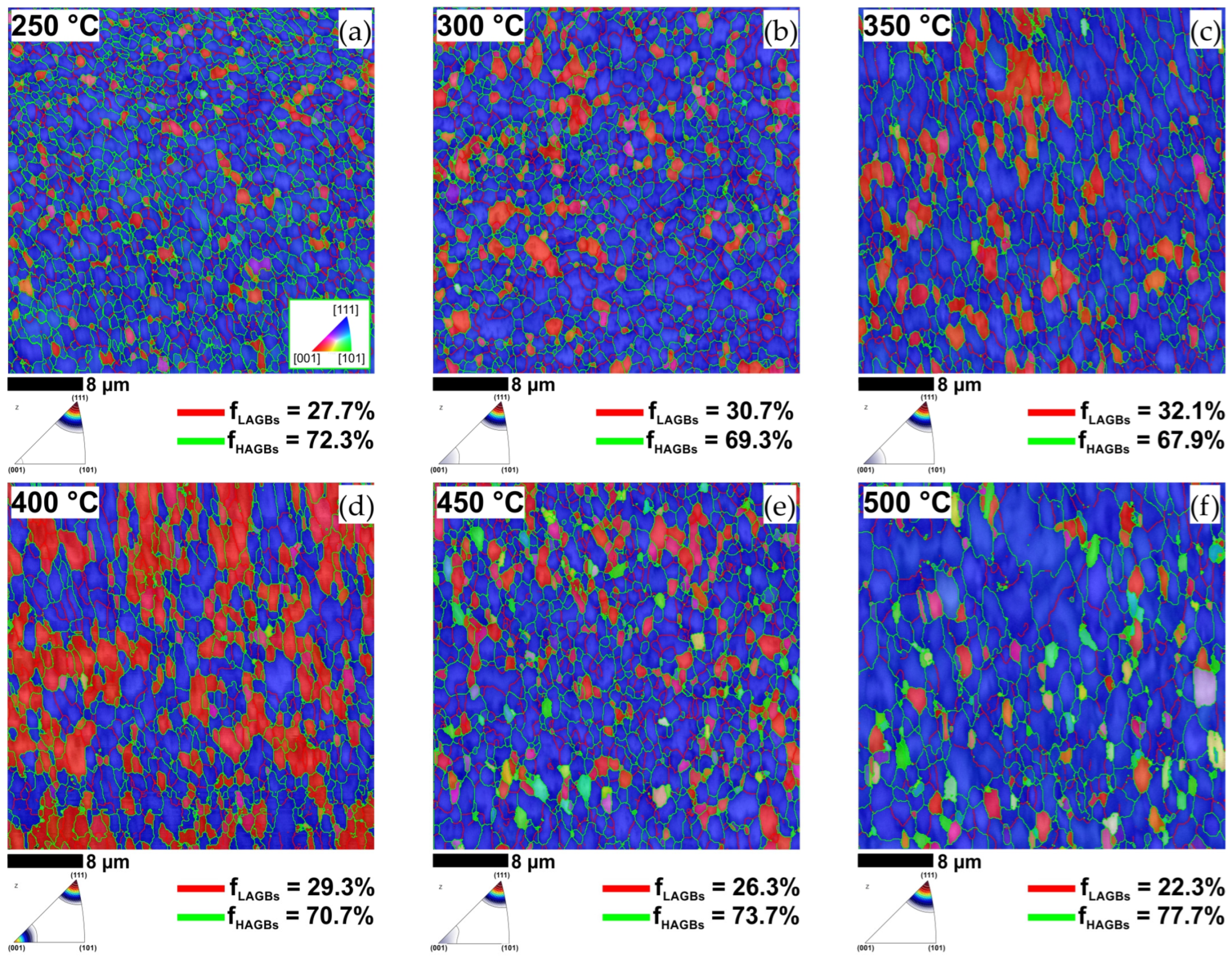
- The ultra-fine-grained microstructure produced by KoBo extrusion was preserved after annealing up to 500 °C.
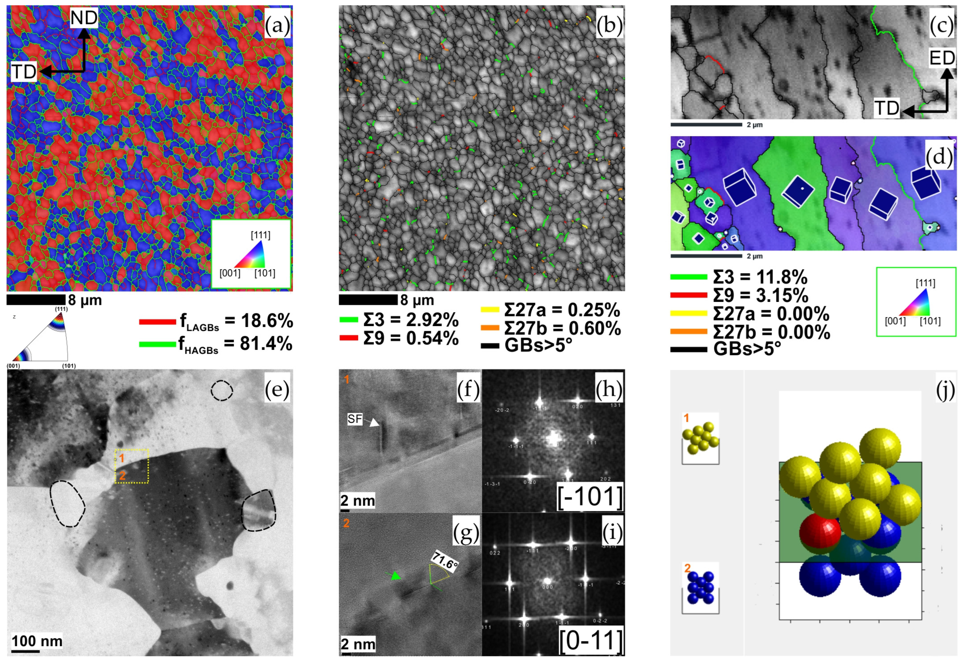
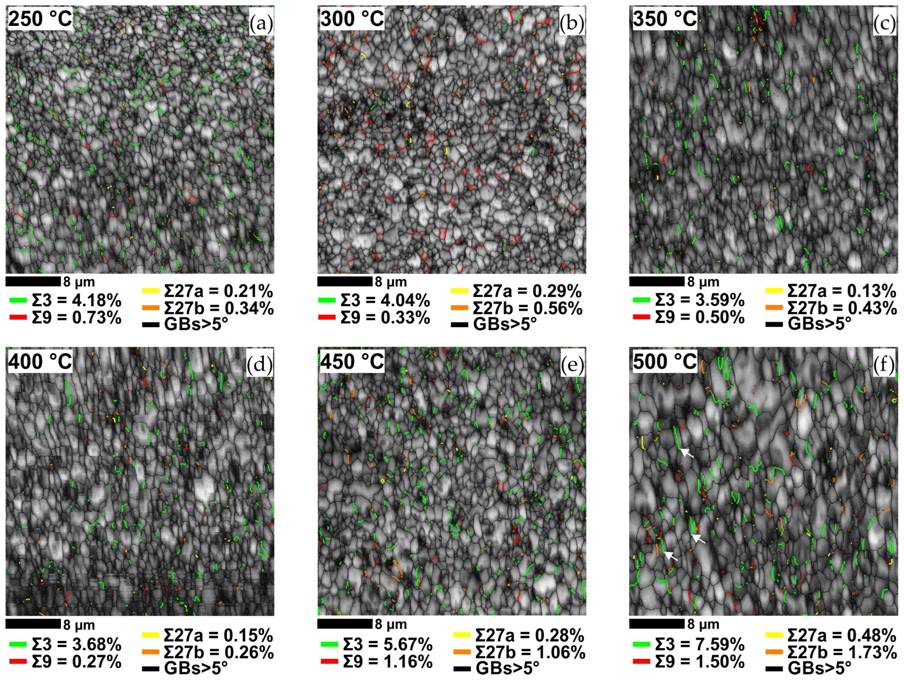
- In the as-printed AlSi10Mg sample, the in situ-formed CSL boundaries accounted for about of 7% of the total boundary fraction.
- The grain boundary character distribution in LPBF AlSI10Mg alloy was optimised in the KoBo extrusion followed by annealing at 500 °C. After this thermomechanical treatment, the population of Σ3, Σ9 and Σ27 was increased to about 11%.
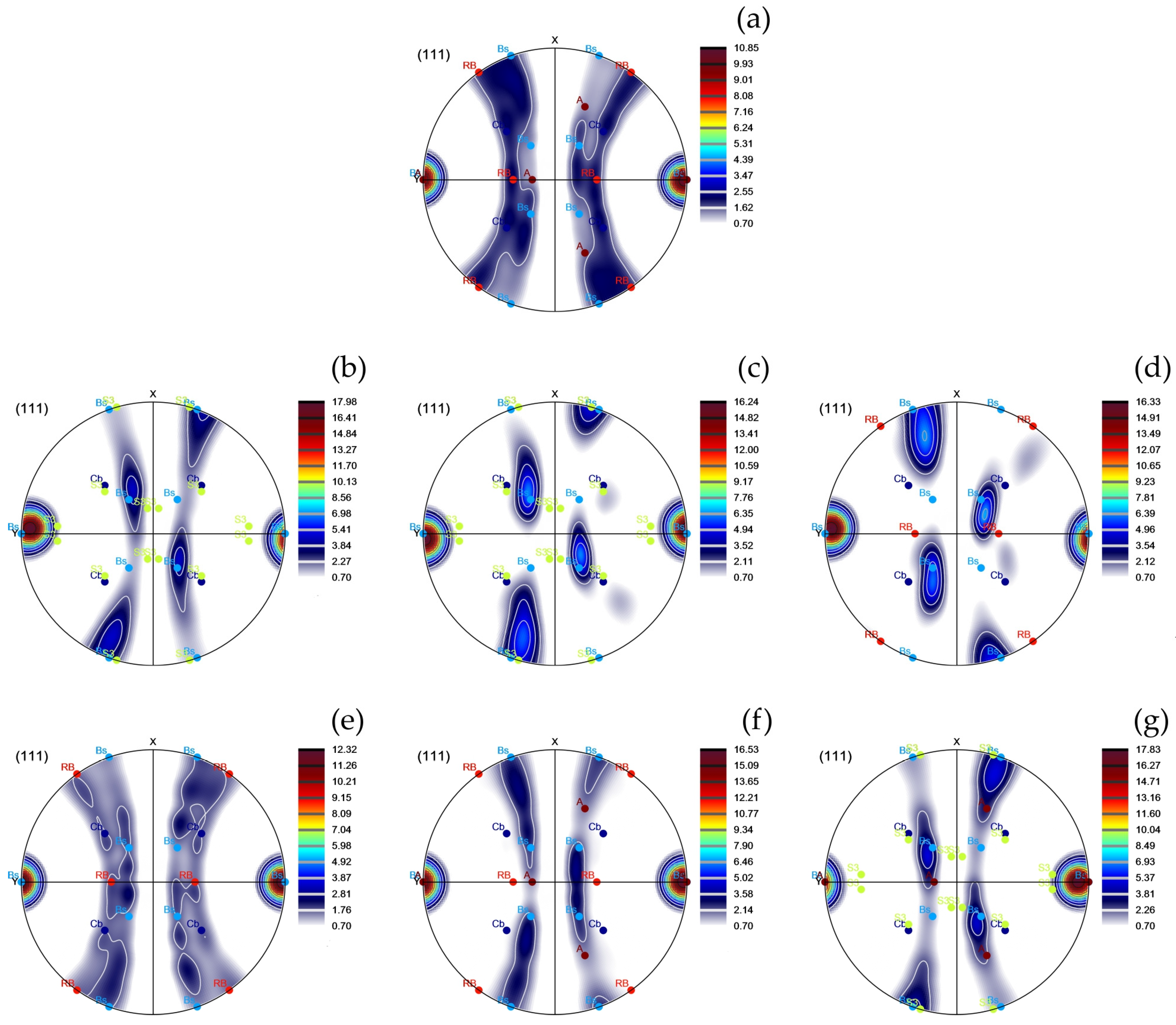
- Strain-induced boundary migration (SIBM) as well as the nucleation of twin boundaries promoted the formation of a strong brass texture in the KoBo-processed samples subjected to recrystallisation annealing.
Funding
Data Availability Statement
Conflicts of Interest
References
- Watanabe, T. An approach to grain boundary design for strong and ductile polycrystals. Res. Mech. 1984, 11, 47–84. [Google Scholar]
- Cao, W.; Xia, S.; Bai, Q.; Zhang, W.; Zhou, B.; Li, Z.; Jiang, L. Effects of initial microstructure on the grain boundary network during grain boundary engineering in Hastelloy N alloy. J. Alloys Compd. 2017, 704, 724–733. [Google Scholar] [CrossRef]
- Guan, X.J.; Shi, F.; Ji, H.M.; Li, X.W. A possibility to synchronously improve the high-temperature strength and ductility in face-centered cubic metals through grain boundary engineering. Scr. Mater. 2020, 187, 216–220. [Google Scholar] [CrossRef]
- Yang, X.; Wang, P.; Huang, M. Grain boundary evolution during low-strain grain boundary engineering achieved by strain-induced boundary migration in pure copper. Mater. Sci. Eng. A 2022, 833, 142532. [Google Scholar] [CrossRef]
- McCarley, J.; Helmink, R.; Goetz, R.; Tin, S. Grain Boundary Engineering of a Low Stacking Fault Energy Ni-based Superalloy. Metall. Mater. Trans. A 2017, 48, 1666–1677. [Google Scholar] [CrossRef]
- Palaparti, D.P.R.; Vijayanand, V.D.; Mariappan, K.; Reddy, G.V.P. Correction: Correlating CSL Evolution and Strain Energy in Single Step Grain Boundary Engineered Austenitic Stainless Steel. Metall. Mater. Trans. A 2023, 54, 2506. [Google Scholar] [CrossRef]
- Ogawa, Y. Temperature-sensitive ductilization in hydrogen-alloyed Fe-Cr-Ni austenitic steel by enhanced deformation twinning. Scr. Mater. 2024, 238, 115760. [Google Scholar] [CrossRef]
- Dammu, S.; Singh, A.P.; Lala, S.R.F.; Srivastava, C. Grain Boundary Engineering in Electrodeposited Tin-Carbon Nanotube Composite Coatings for Enhanced Corrosion Resistance Performance. Metall. Mater. Trans. A 2023, 54, 3928–3939. [Google Scholar] [CrossRef]
- Chen, X.-H.; Wang, F.; Zhang, F. Grain boundary engineering process for nano reinforced aluminum matrix composites. J. Alloys Compd. 2023, 939, 168834. [Google Scholar] [CrossRef]
- Shamanian, M.; Mostaan, H.; Safari, M.; Szpunar, J.A. EBSD Study on Grain Boundary and Microtexture Evolutions During Friction Stir Processing of A413 Cast Aluminum Alloy. J. Mater. Eng. Perform. 2016, 25, 2824–2835. [Google Scholar] [CrossRef]
- Jia, H.; Jin, S.; Li, Y. Formation of Σ3{110} incoherent twin boundaries through geometrically necessary boundaries in an Al-8Zn alloy subjected to one pass of equal channel angular pressing. J. Alloys Compd. 2018, 762, 190–195. [Google Scholar] [CrossRef]
- Pradeep, S.; Jain, V.K.S.; Muthukumaran, S.; Kumar, R. Microstructure and texture evolution during multi-pass friction stir processed AA5083. Mater. Lett. 2021, 288, 129382. [Google Scholar] [CrossRef]
- Liu, B.; Ding, Y.; Xu, J.; Gao, Y.; Chu, C.; Hu, Y.; Chen, D. Grain boundary engineering activated by residual stress during the laser powder bed fusion of Inconel 718 and the electrochemical corrosion performance. Mater. Charact. 2023, 204, 113160. [Google Scholar] [CrossRef]
- Dong, X.; Zhou, Y.; Qu, Y.; Wu, M.; Sun, Q.; Shi, H.; Peng, H.; Zhang, Y.; Xu, S.; Li, N.; et al. Recrystallization behavior and grain boundary character evolution in Co-Cr alloy from selective laser melting to heat treatment. Mater. Charact. 2022, 185, 111716. [Google Scholar] [CrossRef]
- Tokita, S.; Kokawa, H.; Kodama, S.; Sato, Y.S.; Sano, Y.; Li, Z.; Feng, K.; Wu, Y. Suppression of intergranular corrosion by surface grain boundary engineering of 304 austenitic stainless steel using laser peening plus annealing. Mater. Today Commun. 2020, 25, 101572. [Google Scholar] [CrossRef]
- Snopiński, P.; Matus, K.; Łagoda, M.; Appiah, A.N.S.; Hajnyš, J. Engineering an ultra-fine grained microstructure, twins and stacking faults in PBF-LB/M Al-Si alloy via KoBo extrusion method. J. Alloys Compd. 2024, 970, 172576. [Google Scholar] [CrossRef]
- Korbel, A.; Błaż, L.; Bochniak, W.; Pawlyta, M.; Ostachowski, P.; Łagoda, M. Nano-Dimensional Elements in the Structure of Zinc Subjected to KOBO Extrusion. Metallogr. Microstruct. Anal. 2023, 12, 427–432. [Google Scholar] [CrossRef]
- Dobkowska, A.; Zielińska, A.; Paulin, I.; Donik, Č.; Łojkowski, M.; Koralnik, M.; Adamczyk-Cieslak, B.; Paradowski, K.; Tkocz, M.; Kuc, D.; et al. Microstructure and properties of an AZ61 alloy after extrusion with a forward-backward oscillating die without preheating of the initial billet. J. Alloys Compd. 2023, 952, 169843. [Google Scholar] [CrossRef]
- Liu, S.; Wang, Y.; Yarigarravesh, M.; Tayyebi, M.; Tayebi, M. Evaluation of whisker alignment and anisotropic mechanical properties of ZK60 alloy reinforced with SiCw during KOBO extrusion method. J. Manuf. Process. 2022, 84, 344–356. [Google Scholar] [CrossRef]
- Snopiński, P.; Matus, K. Characterisation of Microstructure and Special Grain Boundaries in LPBF AlSi10Mg Alloy Subjected to the KoBo Extrusion Process. Symmetry 2023, 15, 1634. [Google Scholar] [CrossRef]
- Snopiński, P.; Woźniak, A.; Łukowiec, D.; Matus, K.; Tański, T.; Rusz, S.; Hilšer, O. Evolution of Microstructure, Texture and Corrosion Properties of Additively Manufactured AlSi10Mg Alloy Subjected to Equal Channel Angular Pressing (ECAP). Symmetry 2022, 14, 674. [Google Scholar] [CrossRef]
- Korbel, A.; Bochniak, W.; Ostachowski, P.; Błaż, L. Visco-Plastic Flow of Metal in Dynamic Conditions of Complex Strain Scheme. Metall. Mater. Trans. A 2011, 42, 2881–2897. [Google Scholar] [CrossRef]
- Jodi, D.E.; Kitashima, T.; Singh, A.; Watanabe, M. High-temperature microstructural stability of pure Ni fabricated by laser powder bed fusion using Gaussian and flat-top beam profiles. Mater. Charact. 2023, 200, 112897. [Google Scholar] [CrossRef]
- Xue, S.; Kuo, W.; Li, Q.; Fan, Z.; Ding, J.; Su, R.; Wang, H.; Zhang, X. Texture-directed twin formation propensity in Al with high stacking fault energy. Acta Mater. 2018, 144, 226–234. [Google Scholar] [CrossRef]
- Zhu, Z.; Li, W.; Nguyen, Q.B.; An, X.; Lu, W.; Li, Z.; Ng, F.L.; Nai, S.M.L.; Wei, J. Enhanced strength–ductility synergy and transformation-induced plasticity of the selective laser melting fabricated 304L stainless steel. Addit. Manuf. 2020, 35, 101300. [Google Scholar] [CrossRef]
- Monier, L.; Buttard, M.; Veron, M.; Blandin, J.-J.; Martin, G.; Villaret, F.; Shen, Y.; Yrieix, B.; Ernould, C.; Guyon, J.; et al. On the origin of grain refinement and twin boundaries in as-fabricated austenitic stainless steels produced by laser powder bed fusion. Addit. Manuf. 2023, 61, 103351. [Google Scholar] [CrossRef]
- Brandon, D.G. The structure of high-angle grain boundaries. Acta Metall. 1966, 14, 1479–1484. [Google Scholar] [CrossRef]
- Fang, Z.; Xiao, J.; Tan, S.; Deng, C.; Wang, G.; Mao, S.X. Atomic-scale observation of dynamic grain boundary structural transformation during shear-mediated migration. Sci. Adv. 2023, 8, eabn3785. [Google Scholar] [CrossRef]
- Illgen, C.; Bohne, B.; Wagner, M.F.-X.; Frint, P. Thermal stability of SPD-processed aluminum alloys—Internal friction as an indication for recovery, recrystallization and abnormal grain growth. J. Mater. Res. Technol. 2022, 17, 1752–1759. [Google Scholar] [CrossRef]
- Doherty, R.D. The Deformed State and Nucleation of Recrystallization. Met. Sci. 1974, 8, 132–142. [Google Scholar] [CrossRef]
- Randle, V.; Hu, Y. The role of vicinal Σ3 boundaries and Σ9 boundaries in grain boundary engineering. J. Mater. Sci. 2005, 40, 3243–3246. [Google Scholar] [CrossRef]
- Randle, V. Twinning-related grain boundary engineering. Acta Mater. 2004, 52, 4067–4081. [Google Scholar] [CrossRef]
- Laleh, M.; Hughes, A.E.; Tan, M.Y.; Rohrer, G.S.; Primig, S.; Haghdadi, N. Grain boundary character distribution in an additively manufactured austenitic stainless steel. Scr. Mater. 2021, 192, 115–119. [Google Scholar] [CrossRef]
- Goli, F.; Jamaati, R. Significant Texture Weakening of Al-Cu-Mg Alloy by Low Strain Asymmetric Cross Rolling Process. J. Mater. Eng. Perform. 2023, 32, 5576–5582. [Google Scholar] [CrossRef]
- Li, Z.; Chen, L.; Zhang, X.; Zhao, G.; Zhang, C. Strengthening mechanism and anisotropy of mechanical properties of Si3N4p/Al-Mg-Si composites fabricated by sintering and extrusion. Mater. Des. 2021, 210, 110111. [Google Scholar] [CrossRef]
- Yang, W.; Ji, S.; Li, Z.; Wang, M. Grain boundary precipitation induced by grain crystallographic misorientations in an extruded Al–Mg–Si–Cu alloy. J. Alloys Compd. 2015, 624, 27–30. [Google Scholar] [CrossRef]
- Xiao, Z.; Yang, X.; Wang, J.; Fang, Z.; Guo, C.; Zhang, D.; Yang, Y.; Zhang, X. Influence of Fe addition on annealing behaviors of a phosphorus containing brass. J. Alloys Compd. 2017, 712, 268–276. [Google Scholar] [CrossRef]
- Bo, G.; Jiang, F.; Dong, Z.; Wang, G.; Zhang, H. Revealing the influence of pre-precipitation microstructure on hot workability in an Al-Cu-Mg-Zr alloy. Mater. Sci. Eng. A 2019, 755, 147–157. [Google Scholar] [CrossRef]
- Li, X.; Cui, X.; Liu, H.; Zhu, Z.; Liu, J.; Zhang, X.; Cui, H.; Li, H.; Pan, Y.; Feng, R.; et al. Study on the improvement and mechanism of AA6101 electrical conductivity by trace TM (Zr, V, Ti) elements-assisted boron treatment. J. Alloys Compd. 2023, 939, 168728. [Google Scholar] [CrossRef]
- Hjelen, J.; Ørsund, R.; Nes, E. On the origin of recrystallization textures in aluminium. Acta Metall. Mater. 1991, 39, 1377–1404. [Google Scholar] [CrossRef]
- Zhao, Q.; Liu, Z. Texture Evolution of Hot Rolled Al–Cu–Mg–Zr Alloy During Annealing. Met. Mater. Int. 2022, 28, 2947–2961. [Google Scholar] [CrossRef]
- Wang, X.; Xiong, W.; Zheng, Y.; Zhang, J. The Correlation between Texture Evolution and Recrystallization Behavior during Rheologic Forming of 2195 Al–Li Alloy Cylindric Shell. Metals 2023, 13, 853. [Google Scholar] [CrossRef]
- Li, S.; Zhao, Q.; Liu, Z.; Li, F. A Review of Texture Evolution Mechanisms During Deformation by Rolling in Aluminum Alloys. J. Mater. Eng. Perform. 2018, 27, 3350–3373. [Google Scholar] [CrossRef]
- Gusak, A.; Danielewski, M.; Korbel, A.; Bochniak, M.; Storozhuk, N. Elementary model of severe plastic deformation by KoBo process. J. Appl. Phys. 2014, 115, 34905. [Google Scholar] [CrossRef]
- Bate, P.S.; Huang, Y.; Humphreys, F.J. Development of the “brass” texture component during the hot deformation of Al–6Cu–0.4Zr. Acta Mater. 2004, 52, 4281–4289. [Google Scholar] [CrossRef]
- Ihara, K.; Miura, Y. Dynamic recrystallization in Al-Mg-Sc alloys. Mater. Sci. Eng. A 2004, 387–389, 647–650. [Google Scholar] [CrossRef]
- Huang, T.; Liu, F.; Liu, Z.; He, G. Evolution of Microstructure, Texture, and Hardness in an Al-Cu-Mg Alloy during Annealing. J. Mater. Eng. Perform. 2022, 31, 1419–1431. [Google Scholar] [CrossRef]
- Humphreys, F.J.; Hatherly, M. Chapter 12—Recrystallization Textures. In Hatherly MBT-R and RAP, 2nd ed.; Humphreys FJ, Ed.; Elsevier: Oxford, UK, 2004; pp. 379–413. [Google Scholar] [CrossRef]
- Zhao, Q.; Liu, Z.; Li, S.; Huang, T.; Xia, P.; Lu, L. Evolution of the Brass texture in an Al-Cu-Mg alloy during hot rolling. J. Alloys Compd. 2017, 691, 786–799. [Google Scholar] [CrossRef]
- Alvi, M.H.; Cheong, S.W.; Suni, J.P.; Weiland, H.; Rollett, A.D. Cube texture in hot-rolled aluminum alloy 1050 (AA1050)—Nucleation and growth behavior. Acta Mater. 2008, 56, 3098–3108. [Google Scholar] [CrossRef]
- Shen, F.; Zhou, Z.; Li, W.; Sun, Z.; Tian, J.; Xie, C.; Guo, J.; Liao, Z.; Yi, D.; Zhang, J.; et al. Micro-mechanism of texture evolution during isochronal annealing of as-annealed hot rolled Al-Cu-Mg sheet. Mater. Des. 2019, 165, 107575. [Google Scholar] [CrossRef]
- Shen, F.; Yi, D.; Wang, B.; Liu, H.; Jiang, Y.; Tang, C.; Jiang, B. Semi-quantitative evaluation of texture components and anisotropy of the yield strength in 2524 T3 alloy sheets. Mater. Sci. Eng. A 2016, 675, 386–395. [Google Scholar] [CrossRef]
- Zhou, W.; Huo, Q.; Wang, C.; Zhang, Y.; Zhang, Z.; Hu, S.; Zhao, S.; Nagaumi, H.; Yang, X. Effects of texture component, dislocation evolution and precipitation on the creep resistance of T5-treated Al-Mg-Si alloy with different Cu contents. Mater. Charact. 2022, 189, 111981. [Google Scholar] [CrossRef]
- Hirsch, J.; Al-Samman, T. Superior light metals by texture engineering: Optimized aluminum and magnesium alloys for automotive applications. Acta Mater. 2013, 61, 818–843. [Google Scholar] [CrossRef]
- Sakaguchi, N.; Endo, M.; Watanabe, S.; Kinoshita, H.; Yamashita, S.; Kokawa, H. Radiation-induced segregation and corrosion behavior on Σ3 coincidence site lattice and random grain boundaries in proton-irradiated type-316L austenitic stainless steel. J. Nucl. Mater. 2013, 434, 65–71. [Google Scholar] [CrossRef]
- Barnard, L.; Barr, C.M.; Hattar, K.; Morgan, D.; Nathaniel, J.E.; Szlurfarska, I.; Morgan, D.; Taheri, M.L. Grain boundary character dependence of radiation-induced segregation in a model Ni–Cr alloy. J. Mater. Res. 2015, 30, 1290–1299. [Google Scholar] [CrossRef]
- Hu, Y.; Bai, Q.; Xia, S.; Liu, K.; He, Q.; Xu, G. Applying Grain Boundary Engineering and Stabilizing Heat Treatment to 321 Stainless Steel for Enhancing Intergranular Corrosion Resistance. J. Mater. Eng. Perform. 2023. [Google Scholar] [CrossRef]


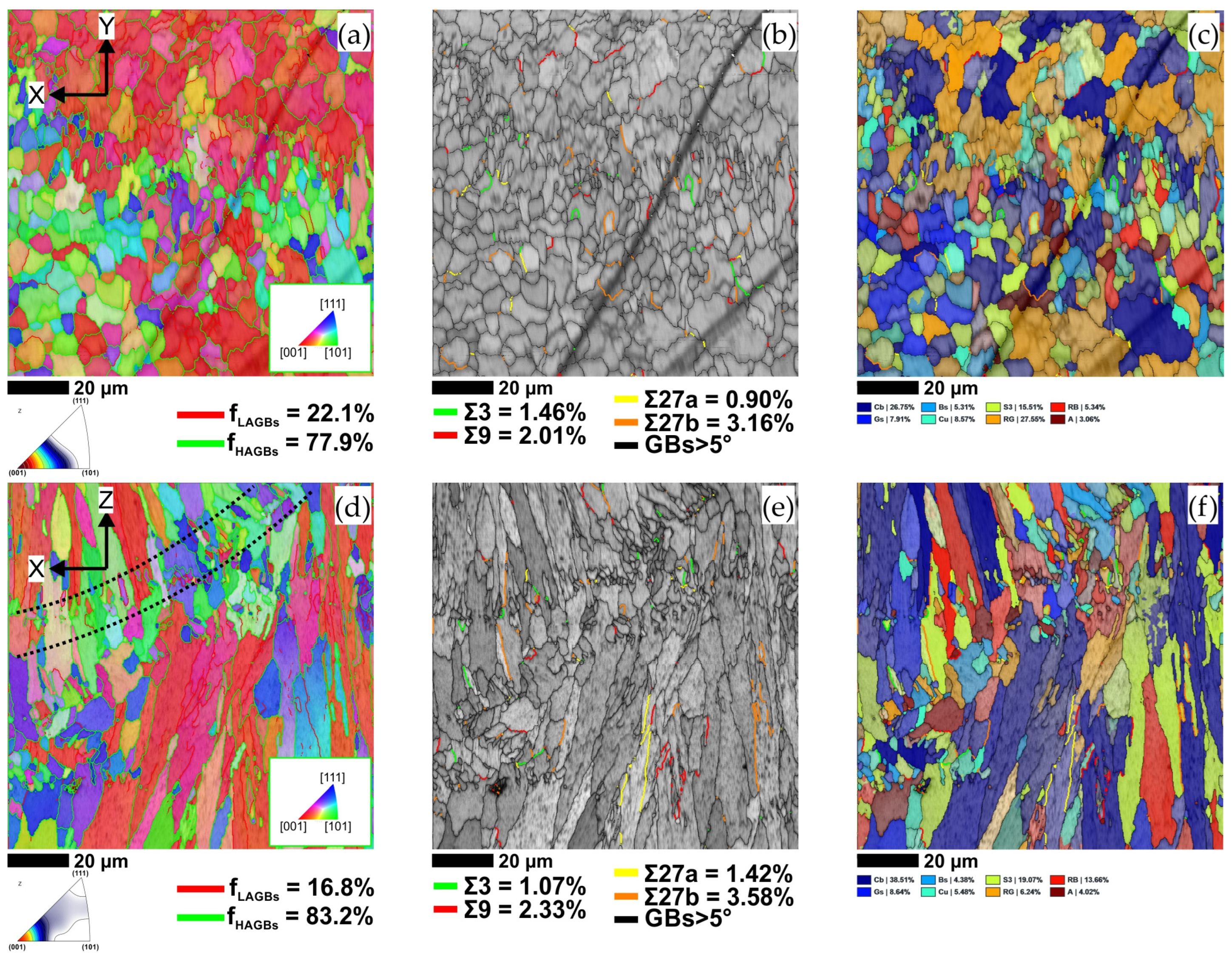
| Texture Component | Cube {001}<100> (%) | Goss {011}<100> (%) | Brass {110}<112> (%) | Copper {112}<111> (%) | S {123}<634> (%) | Rotated Goss (RG) {011}<011> (%) | Rotated Brass (RB) {110}<556> (%) | A {110}<111> (%) |
|---|---|---|---|---|---|---|---|---|
| X–Y plane | 26.75 | 7.91 | 5.31 | 8.57 | 15.51 | 27.55 | 5.34 | 3.06 |
| X–Z plane | 38.51 | 8.64 | 4.38 | 5.48 | 19.07 | 6.24 | 13.66 | 4.02 |
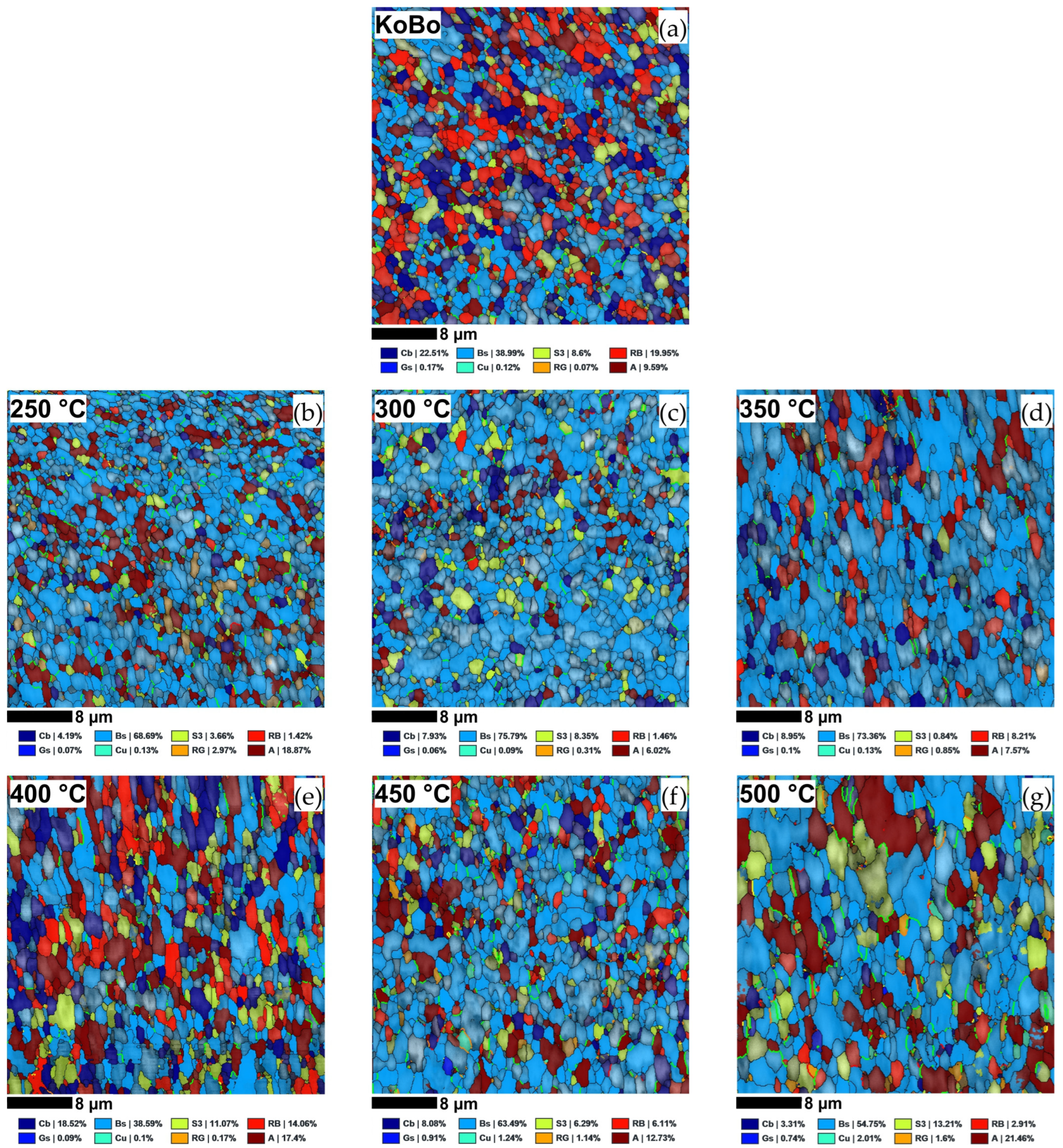
| Texture Component | Cube {001}<100> (%) | Goss {011}<100> (%) | Brass {110}<112> (%) | Copper {112}<111> (%) | S {123}<634> (%) | R. Goss (RG) {011}<011> (%) | R. Brass (RB) {110}<556> (%) | A {112}<110> (%) |
|---|---|---|---|---|---|---|---|---|
| KoBo | 22.51 | 0.17 | 38.99 | 0.12 | 8.6 | 0.07 | 19.95 | 9.59 |
| Annealed at 250 °C | 4.19 | 0.07 | 68.69 | 0.13 | 3.66 | 2.97 | 1.42 | 18.87 |
| Annealed at 300 °C | 7.93 | 0.06 | 75.79 | 0.09 | 8.35 | 0.31 | 1.46 | 6.02 |
| Annealed at 350 °C | 8.95 | 0.1 | 73.36 | 0.13 | 0.84 | 0.85 | 8.21 | 7.57 |
| Annealed at 400 °C | 18.52 | 0.09 | 38.59 | 0.1 | 11.07 | 0.17 | 14.06 | 17.4 |
| Annealed at 450 °C | 8.08 | 0.91 | 63.49 | 1.24 | 6.29 | 1.14 | 6.11 | 12.73 |
| Annealed at 500 °C | 3.31 | 0.74 | 54.75 | 2.01 | 13.21 | 1.6 | 2.91 | 21.46 |
Disclaimer/Publisher’s Note: The statements, opinions and data contained in all publications are solely those of the individual author(s) and contributor(s) and not of MDPI and/or the editor(s). MDPI and/or the editor(s) disclaim responsibility for any injury to people or property resulting from any ideas, methods, instructions or products referred to in the content. |
© 2024 by the author. Licensee MDPI, Basel, Switzerland. This article is an open access article distributed under the terms and conditions of the Creative Commons Attribution (CC BY) license (https://creativecommons.org/licenses/by/4.0/).
Share and Cite
Snopiński, P. Effects of KoBo-Processing and Subsequent Annealing Treatment on Grain Boundary Network and Texture Development in Laser Powder Bed Fusion (LPBF) AlSi10Mg Alloy. Symmetry 2024, 16, 122. https://doi.org/10.3390/sym16010122
Snopiński P. Effects of KoBo-Processing and Subsequent Annealing Treatment on Grain Boundary Network and Texture Development in Laser Powder Bed Fusion (LPBF) AlSi10Mg Alloy. Symmetry. 2024; 16(1):122. https://doi.org/10.3390/sym16010122
Chicago/Turabian StyleSnopiński, Przemysław. 2024. "Effects of KoBo-Processing and Subsequent Annealing Treatment on Grain Boundary Network and Texture Development in Laser Powder Bed Fusion (LPBF) AlSi10Mg Alloy" Symmetry 16, no. 1: 122. https://doi.org/10.3390/sym16010122