Article

Electro-Optical Characteristics of Quasi-Homogeneous Cell in Twisted Nematic Mode

Electrical and Electronic Engineering Course, Graduate School of Engineering Science, Akita University, Akita 010-8502, Japan
*
Author to whom correspondence should be addressed.
Symmetry 2023, 15(3), 597; https://doi.org/10.3390/sym15030597
Submission received: 28 December 2022 / Revised: 17 February 2023 / Accepted: 24 February 2023 / Published: 26 February 2023
(This article belongs to the Special Issue Symmetry and Liquid Crystals)

Abstract

:
A liquid crystal (LC) director distribution was numerically analyzed in 90-degree twisted nematic (TN) LC cells with a symmetric and an asymmetric azimuthal anchoring strength of the alignment substrate and the influence of anchoring strength on the electro-optical property of the TN cell was evaluated. The twist angle decreased with decreasing azimuthal anchoring strength and the LC orientation changed to a homogeneous orientation with the twist angle of 0 degrees in the LC cell with asymmetric azimuthal anchoring strength, specifically with the strong anchoring substrate and the weak anchoring substrate below a critical strength. The asymmetric anchoring LC cell was fabricated by using a poly (vinyl cinnamate) alignment substrate as the weak anchoring surface and a polyimide alignment substrate as the strong anchoring surface. The LC cell performed the dark–bright–dark switching of the transmittance in the crossed polarizers, since the homogeneous LC orientation changed to the TN orientation again with increasing the applied voltage. Therefore, it was experimentally confirmed that LC molecules rotated at 90 degrees in the plane on the alignment surface by the electric field perpendicular to the weak anchoring substrate.

1. Introduction

Twisted nematic liquid crystal (TN LC) configurations [1] are still the most widely used form of liquid crystal display mode. The LC director distribution and electro-optical characteristics of the TN cell are generally determined by the following three features: elastic forces in the LC which are described by Oseen-Frank free-energy density [2], an electric field generated by applying a voltage to electrodes, and anchoring strength of the LC molecules on substrate boundaries [2,3]. The anchoring strength is one of the important design parameters for practical applications. Commercially available TN displays have usually been manufactured using strong azimuthal and polar anchoring surfaces at both sides of the substrate, for example, rubbed polyimide (PI) coated substrates, since the strong anchoring enables fast relaxation from field-driven states. On the other hand, an application of the weak polar anchoring interface has been proposed to decrease the driving voltage of the LC cell. The numerical analysis of the electro-optical property has been reported in the TN display mode [4,5,6,7]. Conversely, the increase in the threshold voltage has been reported if the azimuthal anchoring strength reduces by more than one order of magnitude from 2.0 ×   10 3 to 5.0 ×   10 5 N/m [8]. These studies have usually been carried out the same anchoring strength on both sides of the substrate.
An in-plane switching (IPS) mode [9] is another LC display mode currently used in producing televisions, monitors of personal computers, and various instruments. The IPS mode exhibits a wide viewing angle and a small color shift because LC molecules are initially homogeneously aligned and rotate within a plane parallel to the substrates when an in-plane field is applied. Weak azimuthal anchoring interfaces in the IPS mode have been reported to enlarge the allowable range of marginal variation in the cell gap [10]. Moreover, a threshold behavior has been analyzed in the IPS mode LC cell with asymmetric azimuthal anchoring strength [11]. When the weak azimuthal anchoring alignment film is coated on the interdigital electrode substrate and the counter substrate has strong anchoring strength, the LC molecules glide on the weak azimuthal anchoring surface parallel to the in-plane field direction, which results in the decrease in the driving voltage and the increase in the maximum transmission in the bright state [12,13,14]. The asymmetrical azimuthal anchoring configuration has also been applied to a fringe-field switching (FFS) mode [15]. Higher transmittance was obtained by lower driving voltage compared to the cell with the symmetrical anchoring configuration [16].
We numerically investigated the LC director distribution and electro-optical characteristics in a hybrid-aligned nematic cell with asymmetric anchoring strength [17]. When the planar alignment substrate with the strong polar anchoring and the homeotropic alignment with the weak polar anchoring substrate were combined, the hybrid orientation turned to the homogeneous orientation, which was called a quasi-homogeneous (Q-Homo) cell. A conventional homogeneous LC cell has a threshold voltage of about 1–2 V. However, the Q-Homo cell had no threshold voltage, and neither did the hybrid-aligned nematic cell. Moreover, a large retardation variation was also obtained compared to that in both the hybrid-aligned and homogeneous cells with symmetric strong anchoring. In a guest–host mode, a higher contrast ratio by lower driving voltage was compatible.
The 90-degree TN orientation also changed to the homogeneous orientation between strong anchoring and weak azimuthal anchoring substrates. We called the cell a quasi-homogeneous TN (Q-Homo-TN) cell. The electro-optical characteristics were theoretically estimated in the Q-Homo-TN cell and a unique voltage–transmission curve of 0–100–0% was obtained under the crossed polarizers. The infinite strength of the polar anchoring and the pretilt angle of 0 degrees were set at both sides of the substrate in the above calculations to simplify the analytical model.
In the present paper, finite values of polar and azimuthal anchoring strengths were utilized in the numerical analysis of the LC director distribution in the 90-degree TN and the Q-Homo-TN cells. The finite polar anchoring strength and the non-zero pretilt angle were also considered. Experimentally, a photo-crosslinked poly (vinyl cinnamate) (PVCi) alignment film was used as a variable azimuthal anchoring strength surface. The 90-degree TN and Q-Homo-TN cells were fabricated by adjusting the anchoring strength of the PVCi film surface. Electro-optical characteristics were investigated and voltage–transmission curves were obtained, as well as the theoretical curves.

2. Principle

2.1. Free Energy of TN LC Cell

The LC director distribution was calculated, which is based on the continuum theory. Figure 1 shows the definition of the LC director n, with a tilt angle θ, and a twist angle ϕ, in the TN cell. Wp_0 and Wp_d are the polar anchoring strengths and Wa_0 and Wa_d are azimuthal anchoring strengths at the lower and upper side of the substrates, respectively. The total free energy per unit area, F, in the TN LC cell is given by
F = F bulk + F electric + F surface F bulk + F electric = 0 d 1 2 { ( K 11 cos 2 θ ( z ) + K 33 sin 2 θ ( z ) ) ( d θ ( z ) d z ) 2 + ( K 22 cos 2 θ ( z ) + K 33 sin 2 θ ( z ) ) cos 2 θ ( z ) ( d ϕ ( z ) d z ) 2 ε 0 ( ε + Δ ε sin 2 θ ( z ) ) ( d V ( z ) d z ) 2 } F surface = 1 2 W p 0 sin 2 ( θ 0 θ ( 0 ) ) + 1 2 W p d sin 2 ( θ d θ ( d ) ) + 1 2 W a 0 sin 2 ( ϕ 0 ϕ ( 0 ) ) 1 2 W a d sin 2 ( ϕ d ϕ ( d ) ) ,
where K11, K22, and K33 are the splay, twist, and bend elastic constants; ε is the dielectric constant of the short axis; Δ ε is the dielectric constant anisotropy; d is the thickness of the LC layer; V(z) is the voltage potential. θ 0 and ϕ 0 are polar and azimuthal easy axis angles of the lower side of the substrate, respectively. θ d and ϕ d are angles of easy axes at the upper side of the substrate. In this study, ϕ 0 and ϕ d are set to 0 and 90 degrees; θ 0 and θ d are the pretilt angles generally caused by the rubbing treatment on the polymer surface.

2.2. Critical Anchoring

The liquid crystal director distribution was obtained by minimizing the total free energy of the cell. The finite difference method was used to estimate θ (d) and ϕ (z) in the LC cell. Table 1 shows the physical parameters of 5CB (4-n-pentyl-4′-cyanobiphenyl) which was used in the calculation and the cell fabrication. The cell thickness was 8 μm. Figure 2a,b show the ϕ (0) and ϕ (d) as a function of azimuthal anchoring strength. The polar anchoring strengths and the tilt angles of both sides of the substrate were 1.0 ×   10 3 N/m and 0 degrees, respectively. When the azimuthal anchoring strengths are the same for the substrates (Wa_0 = Wa_d), ϕ (0) increases from 0 degrees, and ϕ (d) decreases from 90 degrees with decreasing the azimuthal anchoring strength, as shown in Figure 2a; ϕ (0) and ϕ (d) reached close to 45 degrees at Wa_d of 1.0 ×   10 10 N/m and the twist angle was, however, about 0.01 degrees.
On the other hand, in the TN LC cell with the asymmetrical anchoring condition with small Wa_d (weak anchoring) and large Wa_0 (strong anchoring), ϕ (0) and ϕ (d) decreased with decreasing Wa_d, as shown in Figure 2b. The twist elastic torque in the bulk overcomes the surface anchoring torque. Thus, the LC director on the weak anchoring surface turns to the direction of the easy axis at the counter strong anchoring substrate [17,18,19]; ϕ (d) was 0 degrees when Wa_d was less than a certain value, which is called the threshold anchoring strength, a critical anchoring strength [17]. The critical anchoring strength was estimated to be 5.0 ×   10 7 N/m (=K22/d) with the infinitely strong Wa_0 [17,19]. When Wa_0 was set to be 1.0 ×   10 4 N/m, which was the typical azimuthal anchoring strengths= of the rubbed PI alignment surface [7], the ϕ (d) curve almost overlapped with that estimated using infinite anchoring strengths (see also the extended figure shown in Figure 2b). To be precise, ϕ(d) was not zero but 4.9 degrees at Wa_d of 5.0 ×   10 7 N/m. If Wa_0 is set to be 1.0 ×   10 5 N/m, the critical anchoring strength is estimated to be 4.8 ×   10 7 N/m; ϕ (0) was 4.1 degrees at Wa_d of 1.0 ×   10 5 (=Wa_0) N/m and it decreased to 0 degrees as well as ϕ (d) at the critical anchoring strength of 4.8 ×   10 7 N/m. Then, the absolute homogeneous LC orientation, that is the Q-Homo-TN, was created by the asymmetric azimuthal anchoring strength.
We also calculated ϕ (d) in the case with non-zero pretilt angle surfaces. When the pretilt angle on both sides of the substrate was 2 degrees, calculated results with an extremely small difference were obtained as those shown in Figure 2a,b. As the pretilt angle increased more, we confirmed the increase in the twist angle between weak anchoring substrates. As the pretilt angle increased from 0 degrees to 10 degrees, the twist angle increased from 42.3 degrees to 43.1 degrees in the TN cell with symmetric azimuthal anchoring strength of 1.0 × 10⁻⁶ N/m, since the twist elastic torque of the LC orientation decreased with increasing the pretilt angle.

3. Electro-Optical Characteristics

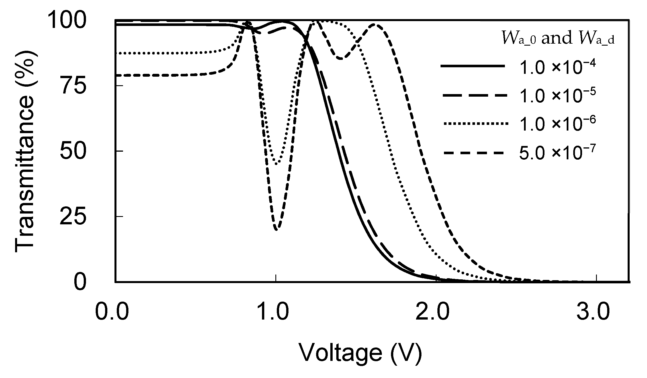
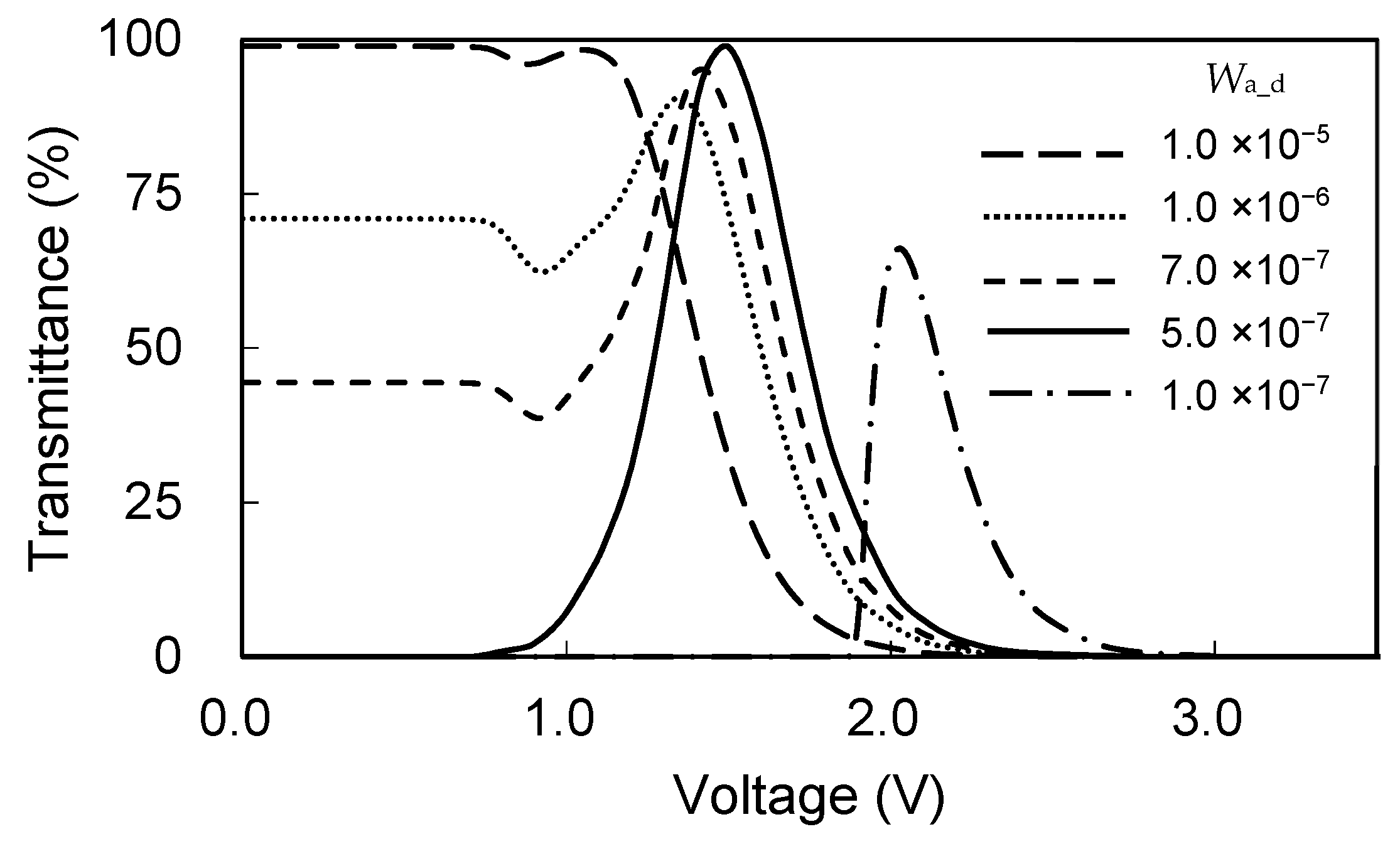
3.1. Theoretical Electro-Optical Characteristics

The electro-optical property of the TN cell was estimated by using Jones matrix calculus at the wavelength of 550 nm. The cell was placed between crossed polarizers and the transmission axes of the polarizer were arranged with the easy axes of the alignment substrate. Figure 3 shows the electro-optical characteristic of the TN cell with the symmetric azimuthal anchoring strength. The polar anchoring of both sides of the substrate was 1.0 ×   10 3 N/m. The tilt angle was set to be 2 degrees assuming the typical rubbed PI surface. The voltage–transmission (V-T) curve with the azimuthal anchoring strength of 1.0 ×   10 4 N/m was almost the same as the V-T curve with using the infinitely strong anchoring. When the anchoring was 1.0 ×   10 5 N/m, the twist angle in the absence of the applied voltage decreased to 81.8 degrees and the curve slightly shift to the right, which has already been reported by Inoue et al. [8]. The driving voltages V10, that is the voltage necessary to obtain the transmittance of 10% in a “black on white mode”, were 1.66 V and 1.71 V in the TN cells with the anchoring strength of 1.0 ×   10 4 and 1.0 ×   10 5 N/m, respectively. The twist angle without the voltage application decreased to 42.4 and 25.8 degrees when the anchoring became symmetrically weak to 1.0 ×   10 6 and 5.0 ×   10 7 N/m 1.0 ×   10 5 N/m, respectively, and V-T curves were significantly changed from the normal V-T curve of the TN mode.
Figure 4 shows the tilt and twist angle distributions in the Q-Homo-TN cell with the asymmetric azimuthal anchoring strength under the voltage application. The azimuthal anchoring strengths of Wa_0 and Wa_d were set to be 1.0 ×   10 4 and 5.0 ×   10 7 N/m, respectively. The θ 0 at the strong azimuthal anchoring surface was 2 degrees; θ d at the weak azimuthal anchoring surface was 0 degrees assuming a very weak rubbed PI or a photoalignment surface. The polar anchoring of both sides of the substrate was 1.0 ×   10 3 N/m. The LC molecules were homogeneously oriented in the voltage-off state. The threshold voltage at which the LC tilt angle at the center of the LC layer began to increase was about 0.4 V and was the same as that in the TN cell using the symmetric strong azimuthal anchoring strength of 1.0 ×   10 4 N/m. The distributions of θ with the respective voltage application were also almost the same as that in the TN cell. On the other hand, ϕ(d) increased with the voltage in the Q-Homo-TN cell, because LC molecules glide on the weak anchoring surface due to the twist torque reduction in bulk [17]. When the applied voltage was 3 V, ϕ (d) reached 90 degrees and the ϕ distribution in the Q-Homo-TN cell was almost identical to that in the TN cell with the symmetric strong anchoring.
Figure 5 shows V-T curves of the TN cells with the parameter of Wa_d. Wa_0 was set to be 1.0 ×   10 4 N/m. The transmittance without the voltage decreased to 0% since the twist angle also decreased to 0 degrees with decreasing Wa_d. In the Q-Homo-TN cells with Wa_d of 5.0 ×   10 7 N/m, θ and ϕ distribution shown in Figure 4 produced the V-T curve which exhibited 0–98.8–0% shift of the transmittance with the applied voltage. The V-T curve shows a display device operating in a “white on black mode” in the drive at the low-voltage side. The driving voltage of V90, which is the voltage necessary to obtain the transmittance of 90%, was about 1.40 V, which shows the lower driving voltage of bright/dark switching compared to that in the TN cell. The maximum transmittance was obtained at 1.50 V and then decreased to 0% again because of the loss of optical rotation. When Wa_d was lower than the critical anchoring of 5.0 ×   10 7 N/m, the threshold voltage and the driving voltage were increased, and the maximum transmittance decreased.
V-T curves at 640 nm ( Δ n = 0.170 ) , 550 nm ( Δ n = 0.184 ) , and 460 nm ( Δ n = 0.204 ) corresponding to red, green, and blue wavelengths are shown in Figure 6. The wavelength dependence of the transmittance was small in the usual TN cell using strong anchoring substrates due to the contribution of optical rotation characteristics, as shown in Figure 6a. In the TN cell using symmetrically weak anchoring substrates, the wavelength dependence was large especially on the low voltage side by a birefringence effect of the LC, as shown in Figure 6b. The V-T curves of the red and green lights were very close, but not for the blue light in the Q-Homo-TN cell, as shown in Figure 6c. The incident light of 460 nm was close to the fourth Mauguin minimum conditions of the 90-degree TN cell [20]. The peak transmittance was improved from 83.5% to more than 90% by using the LC material with smaller Δn such that the second and third Mauguin minimum conditions are satisfied.

3.2. Cell Fabrication
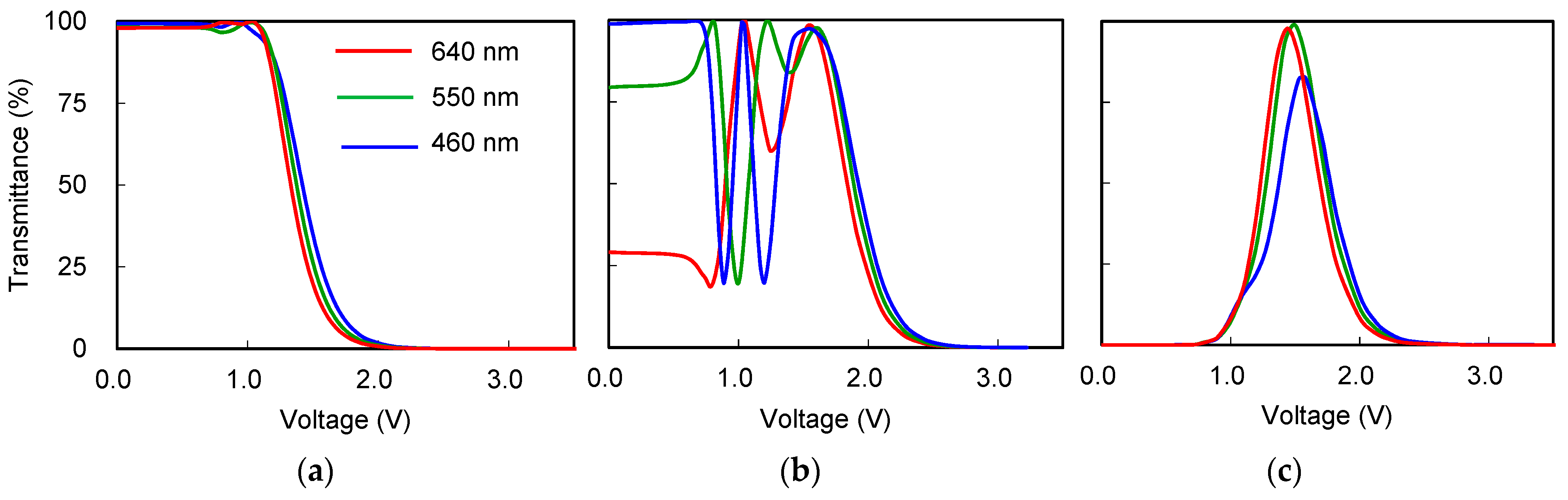
It is known that the azimuthal anchoring strength of the PI film depends on the rubbing strength and the amount of UV irradiation in a photoalignment technology [21,22]. However, these surfaces have usually a strong surface memory effect even without the alignment treatment and have a certain strong azimuthal anchoring strength. The PVCi film is well known as the LC photoalignment fabricated by irradiating with a linearly polarized UV light [23,24,25,26,27]. The azimuthal anchoring of the PVCi surface increases to about 5.0 × 10 6 N/m with the UV dose [24,28], the strength of which is insufficient to achieve the twist angle of 90 degrees. In addition, it was reported that the anchoring strength increased to about 2.0 × 10 5 N/m when the rubbed PVCi film was exposed with linearly polarized UV light [29]. We also exposed the film with unpolarized UV light and obtained the same azimuthal anchoring strength of 2.0 × 10 5 N/m [19].
Figure 7a shows a schematic model of the fabricated LC cell with asymmetric azimuthal anchoring substrates using the rubbed PI (AL-1254 from JSR Corp. Japan) and PVCi surfaces. The cell thickness was controlled by using 9 μm ball spacers. The anchoring strength of the PVCi surface without the UV irradiation was about 8 ×   10 8 N/m. We controlled the anchoring strength by the irradiation time of the UV light from a super-high-pressure Hg lamp source [19]. The UV power was 10 mW/cm2. The left-half part of the rubbed PVCi surface was irradiated with the UV light for 20 s to obtain a target anchoring strength of 4.5 ×   10 7 (=K22/d) N/m. The right-half side was irradiated for 120 s and the anchoring strength was about 1.0 × 10 5 N/m. The easy axis of the rubbed PVCi surface is perpendicular to the rubbing direction [30,31,32]. Accordingly, 5CB was sandwiched between PVCi and PI substrates whose rubbing directions were parallel to each other. Figure 7b shows optical polarizing microscope images of the fabricated LC cell placed between crossed and parallel polarizers. The homogeneous orientation without the twist deformation and the optical rotation of roughly 90 degrees were confirmed on the weak and strong anchoring PVCi surfaces, respectively.

3.3. V-T Curves

Figure 8 shows the voltage–transmittance curves of the fabricated LC cell. The transmitted light intensity through parallel polarizers in the absence of the LC cell was defined as 100%. The wavelength of the incident light was 640 nm. The rate of the voltage sweep was 2 V/min. When the Q-Homo-TN cell was placed between crossed polarizers, the transmittance increased from 0% to 60% and then decreased to 0% again with increasing the voltage. This indicates that the in-plane rotation of the LC on the weak anchoring PVCi surface occurred, and the LC orientation changed from the homogeneous to TN orientation, as shown by the numerical results in Figure 4b. The hysteresis characteristics were observed with increasing and decreasing voltages. The in-plane switching mode cell using the PVCi surface has also been reported to exhibit a hysteresis characteristic [33,34]. It has also been reported that the high viscosity of the gliding LC molecules on the surface caused a very slow response [35,36,37]. Therefore, the hysteresis characteristic of the Q-Homo-TN cell might be caused by the slow response of the in-plane rotation of the LC on the PVCi surface. On the other hand, in the TN orientation between rubbed PI and fully crosslinked PVCi surfaces, a common V-T curve of the TN cell without hysteresis was obtained when the voltage sweep rate was 5 V/min.
We calculated the theoretical V-T curves using the following data: the polar and azimuthal anchoring strengths of the rubbed PI are 1.0 × 10 3 and 4.0 ×   10 4 N/m, respectively. The pretilt angle is about 2 degrees. The polar anchoring strength of PVCi is 1.0 × 10 4 N/m [27]. The pretilt angle of the PVCi surface is 0 degrees since the LC aligns perpendicular to the rubbing direction. Converting the peak value of the measurement curve to 100%, the V-T curve of the fabricated TN cell was in close agreement with the calculated value at 640 nm. In the Q-Homo-TN cell, the measured peak transmittance was obtained at 1.46 V with the voltage increase, which almost coincides with the calculated peak voltage, even though the peak value in the fabricated cell was lower than the calculated peak value of 99.0%. Some alignment defects generated through the rubbing treatment on the uncrosslinked PVCi surface resulted in a lower peak value of the transmittance. In addition, the transmittance became maximum at 1.33 V and the peak value was higher than that increasing the voltage. The calculated results of the director distributions shown in Figure 4 were in the steady-state liquid crystal reorientation states, and the hysteresis properties as reported in highly twisted nematic cells [38,39] were not confirmed in our calculation.
Another problem with using the weak anchoring surface has been reported as an alignment memory effect [12,40]. Some kinds of alignment film have been proposed as the weak anchoring surface without the memory effect, for example a para-PVCN-F [12] surface and a high-density, concentrated brush poly (n-hexyl methacrylate) grafted substrate [13,14]. These alignment films and further studies on relations between the weak anchoring surface and the liquid crystal interface will lead to better performance of this device.

4. Conclusions

The electro-optical characteristics in the TN cell with symmetric and asymmetric anchoring strength were investigated. The Q-Homo-TN orientation was successfully fabricated using the rubbed PI surface and the PVCi surface, in which azimuthal anchoring strength was adjusted to the critical value. The dark–bright–dark switching of the Q-Homo TN cell was observed in the crossed polarizers when applying the voltage, which indicates the 90-degree in-plane rotation of LC molecules by the electric field perpendicular to the substrate. The hysteresis characteristics of the V-T curve were observed in the fabricated Q-Homo-TN cell, which was not shown in the claustration. In future work, we intend to further investigate response and decay times at various anchoring strengths by changing the crosslinking degree.

Author Contributions

Conceptualization, R.Y.; Methodology, cell fabrication, and evaluation, R.Y. and Y.S.; Writing—original draft preparation, R.Y.; Writing—review and editing, R.Y. and Y.S. All authors have read and agreed to the published version of the manuscript.

Funding

This research received no external funding.

Data Availability Statement

Not applicable.

Conflicts of Interest

The authors declare no conflict of interest.

References

  1. Schadt, M.; Helfrich, W. Voltage-dependent optically activity of a twisted nematic liquid crystal. Appl. Phys. Lett. 1971, 18, 127–128. [Google Scholar] [CrossRef]
  2. de Gennes, P.G. The Physics of Liquid Crystals; Clarendon: Oxford, UK, 1974; pp. 59–79. [Google Scholar]
  3. Rapini, A.; Papoular, M. Distorsion d’une lamelle nematique sous champ magnetique conditions d’ancrage aux parois. J. Phys. (Paris) Colloq. 1969, 30, C4-54–C4-56. [Google Scholar] [CrossRef]
  4. Nehring, J.; Kmetz, A.R.; Scheffer, T.J. Analysis of weak-boundary-coupling effects in liquid-crystal displays. J. Appl. Phys. 1976, 47, 850–857. [Google Scholar] [CrossRef]
  5. Sprang, H.A.; Breddels, P.A. Numerical calculations of director patterns in highly twisted nematic configurations with nonzero pretilt angles. J. Appl. Phys. 1986, 60, 968–972. [Google Scholar] [CrossRef]
  6. Hirning, R.; Funk, W.; Trebin, H.-R.; Schmidt, M.; Schmiedel, H. Threshold behavior and electro-optical properties of twisted nematic layers with weak anchoring in the tilt and twist angle. J. Appl. Phys. 1991, 70, 4211–4216. [Google Scholar] [CrossRef]
  7. Ishihara, S.; Mizusaki, M. Alignment control technology of liquid crystal molecules. J. Soc. Inf. Disp. 2019, 28, 44–74. [Google Scholar] [CrossRef]
  8. Inoue, M.; Manabe, N.; Akahane, T. Influence of the azimuth anchoring energy on the electro-optical characteristics of LCDs. In Proceedings of the 5th International Display Workshop, LCTp2–1. Kobe, Japan, 7–9 December 1998; pp. 41–44. [Google Scholar]
  9. Oh-e, M.; Kondo, K. Electro-optical characteristics and switching behavior of the in-plane switching mode. Appl. Phys. Lett. 1995, 67, 3895–3897. [Google Scholar] [CrossRef]
  10. Yoneya, M.; Iwasaki, K.; Tomioka, Y.; Kondo, K. Cell gap margin enlargement of in-plane switching mode liquid crystal displays using weak-anchoring effects. Appl. Phys. Lett. 1999, 74, 803–805. [Google Scholar] [CrossRef]
  11. Yoneya, M.; Kondo, K. Threshold behavior analysis of in-plane switching mode liquid-crystal cells with asymmetrical surface condition. Appl. Phys. Lett. 1999, 74, 3477–3479. [Google Scholar] [CrossRef]
  12. Andrienko, D.; Barbet, F.; Bormann, D.; Kurioz, Y.; Kwon, S.-B.; Reznikov, Y.; Warenghem, M. Electrically controlled director slippage over a photosensitive aligning surface; in-plane sliding mode. Liq. Cryst. 2000, 27, 365–370. [Google Scholar] [CrossRef]
  13. Sato, O.; Iwata, N.; Kawamura, J.; Maeda, T.; Tsujii, Y.; Watanabe, J.; Tokita, M. An in-plane switching liquid crystal cell with weakly anchored liquid crystals on the electrode substrate. J. Mater. Chem. C 2017, 5, 4384–4387. [Google Scholar] [CrossRef]
  14. Sato, O.; Okuno, H.; Adachi, I.; Goto, K.; Noda, T.; Tsutsui, K. A high transmittance and fast response in-plane switching liquid crystal display with the zero-azimuth anchoring layers on the electrodes. J. Phys. D Appl. Phys. 2020, 53, 15LT02. [Google Scholar] [CrossRef]
  15. Lee, S.H.; Lee, S.L.; Kim, H.Y. Electro-optic characteristics and switching principle of a nematic liquid crystal cell controlled by fringe-field switching. Appl. Phys. Lett. 1998, 73, 2881–2883. [Google Scholar] [CrossRef]
  16. Choi, Y.; Oh, S.-W.; Choi, T.-H.; Sohn, H.-J.; Do, S.-M.; Yoon, T.-H. Liquid crystal cell asymmetrically anchored for high transmittance and triggered with a vertical field for fast switching. Opt. Express 2020, 28, 20553–20562. [Google Scholar] [CrossRef] [PubMed]
  17. Yamaguchi, R. Analysis of Electro-Optical Behavior in Liquid Crystal Cells with Asymmetric Anchoring Strength. Symmetry 2022, 14, 85. [Google Scholar] [CrossRef]
  18. Strigazzi, A. On the critical thickness of a twisted nematic cell. J. Phys. 1985, 46, 1507–1512. [Google Scholar] [CrossRef]
  19. Yamaguchi, R.; Sato, S. Continuous grey scale image printing on the liquid crystal cell. Appl. Phys. Lett. 2005, 86, 031913-1–031913-3. [Google Scholar] [CrossRef]
  20. Gooch, C.H.; Tarry, H.A. The optical properties of twisted nematic liquid crystal structures with twist angles ⩽90 degrees. J. Phys. D Appl. Phys. 1975, 8, 1575–1584. [Google Scholar] [CrossRef]
  21. Seo, D.-S. Relationship between surface anchoring strength and surface ordering on weakly rubbed polyimide surfaces. Liq. Cryst. 2001, 27, 1539–1542. [Google Scholar] [CrossRef]
  22. Hasegawa, M. Modeling of photoinduced optical anisotropy and anchoring energy of polyimide exposed to linearly polarized deep UV Light. Jpn. J. Appl. Phys. 1999, 38, L457–L460. [Google Scholar] [CrossRef]
  23. Schadt, M.; Schmitt, K.; Kozinkov, V.; Chigrinov, V. Surface-induced parallel alignment of liquid crystals by linearly polymerized photopolymers. Jpn. J. Appl. Phys. 1992, 31, 2155–2164. [Google Scholar] [CrossRef]
  24. Bryan-Brown, G.P.; Sage, I.C. Photoinduced ordering and alignment properties of polyvinylcinnamates. Liq. Cryst. 1996, 20, 825–829. [Google Scholar] [CrossRef]
  25. Chen, J.; Johnson, D.L.; Bos, P.J.; Wang, X.; West, J.L. Model of liquid crystal alignment by exposure to linearly polarized ultraviolet light. Phys. Rev. E 1996, 54, 1599–1603. [Google Scholar] [CrossRef]
  26. Ichimura, K.; Akita, Y.; Akiyama, H.; Kudo, K.; Hayashi, Y. Photoreactivity of polymers with regioisomeric cinnamate side chains and their ability to regulate liquid crystal alignment. Macromolecules 1997, 30, 903–911. [Google Scholar] [CrossRef]
  27. Iimura, Y.; Kobayashi, S.; Hashimoto, T.; Sugiyama, T.; Katoh, K. Alignment control of liquid crystal molecules using photodimerization reaction of poly (vinyl cinnamate). IEICE Trans. Electron. 1996, E79-C, 1040–1046. [Google Scholar]
  28. Vilfan, M.; Olenik, I.D.; Mertelj, A.; Copic, M. Aging of surface anchoring and surface viscosity of a nematic liquid crystal on photoaligning poly-(vinyl-cinnamate). Phys. Rev. E 2001, 63, 061709-1–061709-5. [Google Scholar] [CrossRef] [PubMed]
  29. Li, X.T.; Saitoh, H.; Nakamura, H.; Kobayashi, S.; Iimura, Y. Mechanism of photo-induced liquid crystal alignment on polyvinyl cinnamate surface. J. Photopolym. Sci. Technol. 1997, 10, 13–17. [Google Scholar] [CrossRef]
  30. Yamaguchi, R.; Goto, Y.; Sato, S. A novel patterning method of liquid crystal alignment by azimuthal anchoring control. Jpn. J. Appl. Phys. 2002, 41, L889–L891. [Google Scholar] [CrossRef]
  31. Yamaguchi, R.; Sato, S. Liquid crystal material dependence on rubbed PVCi alignment properties. Mol. Cryst. Liq. Cryst. 2010, 516, 32–37. [Google Scholar] [CrossRef]
  32. Yamaguchi, R.; Nishimura, M.; Ikeya, M. Azimuthal anchoring change by liquid crystal mixtures on poly (vinyl Cinnamate) film. J. Photopolym. Sci. Technol. 2013, 26, 393–396. [Google Scholar] [CrossRef]
  33. Zhou, Y.; Sato, S. Electrooptical and response/relaxation properties of liquid crystal cells in in-plane switching mode with polyvinylcinnamate photoinduced alignment layer. Jpn. J. Appl. Phys. 1998, 37, 4439–4443. [Google Scholar] [CrossRef]
  34. Li, X.T.; Kawakami, A.; Akiyama, H.; Kobayashi, S.; Iimura, Y. Reduction in driving voltage of in-plane switching liquid crystal displays using photo-alignment method. Jpn. J. Appl. Phys. 1998, 37, L743–L745. [Google Scholar] [CrossRef]
  35. Kurioz, Y.; Reshetniak, V.; Reznikov, Y. Orientation of a liquid crystal on a soft photoaligning surface. Mol. Cryst. Liq. Cryst. 2002, 375, 535–541. [Google Scholar] [CrossRef]
  36. Buluy, O.; Iljin, A.; Ouskova, E.; Reznikov, Y.; Blanc, C.; Nobili, M.; Antonova, K. Anchoring and gliding of easy axis of 5CB on photoaligning PVCN-F surface. J. Soc. Inf. Disp. 2006, 14, 603–610. [Google Scholar] [CrossRef]
  37. Mema, E.; Kondic, L.; Cummings, L.J. Director gliding in a nematic liquid crystal layer: Quantitative comparison with experiments. Phys. Rev. E 2018, 97, 032704. [Google Scholar] [CrossRef]
  38. Saito, S.; Kamihara, M.; Kobayashi, S. Influence on the hysteresis effect of various parameters in supertwisted nematic liquid crystals. Mol. Cryst. Liq. Cryst. 1986, 139, 171–187. [Google Scholar] [CrossRef]
  39. Li, J.; Hoke, C.D.; Bos, P.J. Studies of the Bistability of Highly Twisted Nematics. Jpn. J. Appl. Phys. 1996, 35, L706. [Google Scholar] [CrossRef]
  40. Prakash, J.; Choudhary, A.; Kaur, S.; Mehta, D.S.; Biradar, A.M. Memory effect in weakly anchored surfaces of deformed helix ferroelectric liquid crystals. Phys. Rev. E 2008, 78, 021707. [Google Scholar] [CrossRef] [PubMed]
Figure 1. Definition of the LC director, n, and surface alignment conditions of the substrate in the TN cell.
Symmetry 15 00597 g001
Figure 2. The ϕ (0) and ϕ (d) as a function of Wp_d in the TN cell with (a) symmetric and (b) asymmetric anchoring strengths of the alignment surfaces with the parameter of Wa_0.
Symmetry 15 00597 g002
Figure 3. Voltage–transmittance curves of the TN cell with the symmetric azimuthal anchoring strength.
Symmetry 15 00597 g003
Figure 4. Director distribution of (a) θ and (b) ϕ in the Q-Homo-TN cell with Wa_0 of 1.0 ×   10 4 N/m and Wa_d of 5.0 ×   10 7 N/m.
Symmetry 15 00597 g004
Figure 5. Voltage–transmittance curves of the TN cell with the asymmetric azimuthal anchoring strength.
Symmetry 15 00597 g005
Figure 6. Voltage–transmittance curves at the wavelength of 640, 550, and 450 nm in the TN cell with the symmetric anchoring strength of (a) 1.0 ×   10 4 N/m, (b) 5.0 ×   10 6 N/m, and (c) in the Q-Homo-TN cell with the asymmetric anchoring strength of 1.0 ×   10 4 and 5.0 ×   10 6 N/m.
Symmetry 15 00597 g006
Figure 7. (a) Schematic model of the LC orientation of the Q-Homo-TN and TN between rubbed PVCi and PI substrates. (b) Optical polarizing microscope images of the LC cell placed between crossed and parallel polarizers.
Symmetry 15 00597 g007
Figure 8. Voltage–transmittance curves of the Q-Homo-TN and TN cells at 640 nm.
Symmetry 15 00597 g008
Table 1. Physical parameters of the LC.
K11K22K33 [pN]ε//εnone (550 nm)
6.348.4 17.96.91.5401.724
Disclaimer/Publisher’s Note: The statements, opinions and data contained in all publications are solely those of the individual author(s) and contributor(s) and not of MDPI and/or the editor(s). MDPI and/or the editor(s) disclaim responsibility for any injury to people or property resulting from any ideas, methods, instructions or products referred to in the content.

