
New Diluter Solubilized in Liquid Crystal Compounds for High Stability and Fast Response Speed Liquid Crystal Displays


Abstract
:1. Introduction
2. Experimental
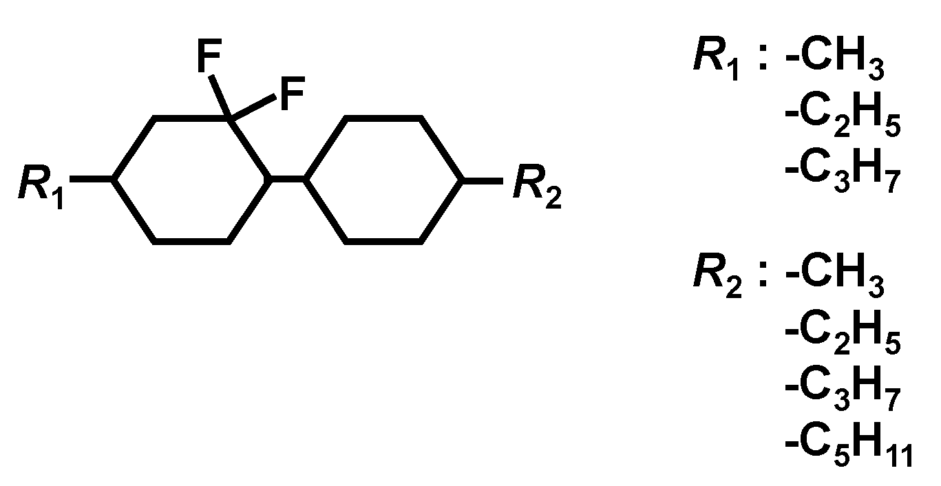
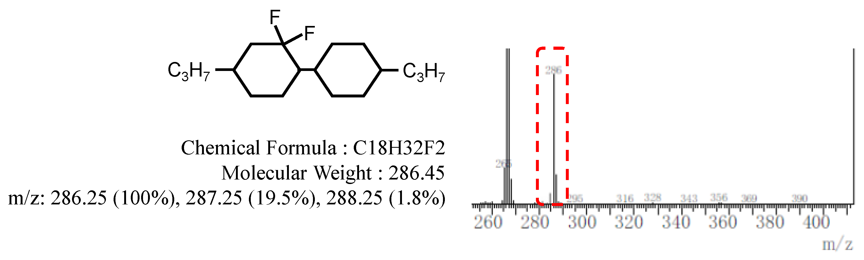
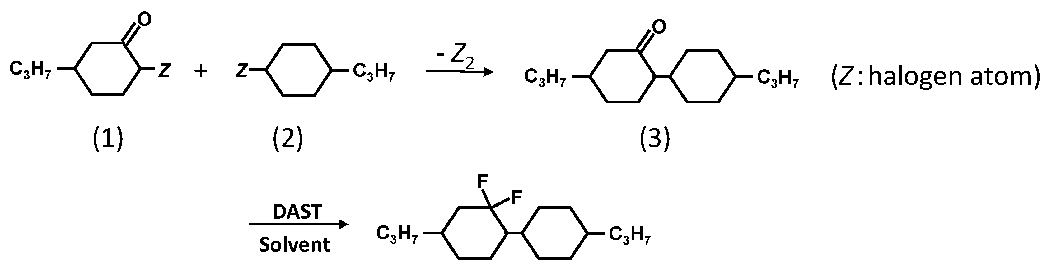
2.1. Preparation of a New Diluter C3-CyFF-CyC3
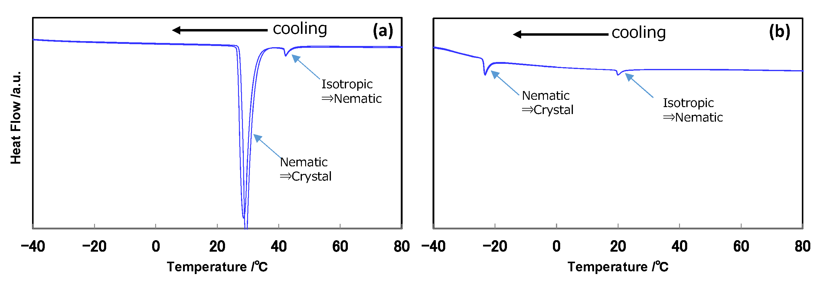
2.2. DSC Evaluation
2.3. Evaluation of the LC Cells
3. New Developed Diluters
4. PS-VA Mode
4.1. Materials
4.2. Preparation of the PS-VA LC Cells
4.3. Evaluation of the PS-VA Cell
5. PI-Free IPS Mode
5.1. Materials
5.2. Preparation of the PI-Free IPS Cell
5.3. Evaluation of the PI-Free IPS Cell
6. Conclusions
Author Contributions
Funding
Institutional Review Board Statement
Informed Consent Statement
Data Availability Statement
Conflicts of Interest
References
- Hanaoka, K.; Nakanishi, Y.; Inoue, Y.; Tanuma, S.; Koike, Y.; Okamoto, K. A new MVA-LCD by polymer sustained alignment technology. In SID Symposium Digest of Technical Papers; Blackwell Publishing Ltd.: Oxford, UK, 2004; Volume 35, pp. 1200–1203. [Google Scholar]
- Nakanishi, Y.; Hanaoka, K.; Shibasaki, M.; Okamoto, K. Relation between monomer structure and image sticking phenomenon of polymer-sustained-alignment liquid crystal displays. Jpn. J. Appl. Phys. 2011, 50, 051702. [Google Scholar] [CrossRef]
- Lee, S.H.; Kim, S.M.; Wu, S.-T. Emerging vertical-alignment liquid-crystal technology associated with surface modification using UV-curable monomer. J. Soc. Inf. Disp. 2009, 17, 551–559. [Google Scholar] [CrossRef]
- Momoi, Y.; Kwak, M.; Choi, D.; Choi, Y.; Jeong, K.; Koda, T.; Haba, O.; Yonetake, K. Polyimide-free LCD by dissolving dendrimers. J. Soc. Inf. Disp. 2012, 20, 486–492. [Google Scholar] [CrossRef]
- Haba, O.; Itabashi, H.; Sato, S.; Machida, K.; Koda, T.; Yonetake, K.; Kwak, M.; Momoi, Y.; Kim, N.; Hong, S.; et al. UV-induced stable planar alignment of nematic liquid crystals using a polypropyleneimine dendrimer having a mesogen consisting of cinnamate and azobenzene moieties. Mol. Cryst. Liq. Cryst. 2015, 610, 201–209. [Google Scholar] [CrossRef]
- Plummer, E.A.; Klasen-Memmer, M.; Fortte, R.; Haensel, H.; Archetti, G. The evolution of the vertically aligned liquid crystal display. In SID Symposium Digest of Technical Papers; Blackwell Publishing Ltd.: Oxford, UK, 2018; Volume 49, pp. 449–452. [Google Scholar]
- Lan, S.; Chen, X.; Wei, H.; Wu, L.; Tseng, T.-J.; Hsieh, C.-C.; Chen, H.-H.; Lin, H.-C.; Lee, Y.-H. Self-alignment of liquid crystal for multi-domain liquid-crystal display. In SID Symposium Digest of Technical Papers; Blackwell Publishing Ltd.: Oxford, UK, 2018; Volume 49, pp. 453–454. [Google Scholar]
- Jeong, I.H.; Yu, J.H.; Jin, H.-S.; Song, K.H.; Kimura, M.; Lee, S.H. Novel approach to achieve conventional polyimide-less IPS/FFS LCDs. In SID Symposium Digest of Technical Papers; Blackwell Publishing Ltd.: Oxford, UK, 2014; Volume 45, pp. 1418–1420. [Google Scholar]
- Park, Y.; Kim, S.; Lee, E. A study on reducing image-sticking artifacts in wide-screen TFT-LCD monitors. J. Soc. Inf. Disp. 2007, 15, 969–973. [Google Scholar] [CrossRef]
- Saito, M. Liquid Crystal Composition and Liquid Crystal Display Element. Japan Patent 5,565,316 B2, 14 June 2017. [Google Scholar]
- Melanie, K.M.; Dagmar, K.; Matthias, B. Liquid-Crystalline Medium. Japan Patent 4,562,357 B2, 13 October 2010. [Google Scholar]
- Okamoto, K.; Shibata, T. Cyclohexane Compound and Liquid Crystal Composition Containing the Same. U.S. Patent 8858829 B2, 14 October 2014. [Google Scholar]
- Bremer, M.; Naemura, S.; Tarumi, K. Model of ion solvation in liquid crystal cells. Jpn. J. Appl. Phys. 1998, 37, L88–L90. [Google Scholar] [CrossRef]
- Huh, I.-K.; Kim, Y.-B. Fluoro-isothiocyanated liquid crystal materials with high dielectric anisotropy and voltage holding ratio. Jpn. J. Appl. Phys. 2002, 41, 6466–6470. [Google Scholar] [CrossRef]
- Oh-e, M.; Umeda, Y.; Ohta, M.; Aratani, S.; Kondo, K. Unusual voltage-holding ratio characteristics using in-plane switching of nematic liquid crystals. Jpn. J. Appl. Phys. 1997, 36, L1025–L1028. [Google Scholar] [CrossRef]
- Inoue, M. Review of various measurement methodologies of migration ion influence on LCD image quality and new measurement proposal beyond LCD materials. J. SID 2020, 28, 92–110. [Google Scholar] [CrossRef]
- Ichinose, H. Advanced liquid crystal mixture development for high performance liquid crystal displays. Ekisho 2011, 15, 174–186. [Google Scholar]
- Mizusaki, M. Polarised UV-induced homogeneous alignment for fringe-field switching liquid crystal display with a new azobenzene monomer. Liq. Cryst. 2019, 46, 640–648. [Google Scholar] [CrossRef]
- Mizusaki, M.; Tsuchiya, H.; Itoh, T.; Minoura, K. Homogeneous self-alignment technology without forming conventional alignment layers. In SID Symposium Digest of Technical Papers; Blackwell Publishing Ltd.: Oxford, UK, 2018; Volume 49, pp. 455–458. [Google Scholar]


| Chemical Structure | Product Name | C⇔N Transition Temperature [°C] | N⇔I Transition Temperature [°C] | C⇔I Transition Temperature [°C] | Decomposition Temperature [°C] |
|---|---|---|---|---|---|
 | C1-CyFF-Cy-C3 | - | - | −5.3 | - |
 | C2-CyFF-Cy-C2 | - | - | 6.2 | - |
 | C2-CyFF-Cy-C3 | - | - | 0.1 | 201 |
 | C3-CyFF-Cy-C1 | −15.5 | 5.5 | - | 210 |
 | C3-CyFF-Cy-C2 | −29.0 | 2.5 | - | 206 |
 | C3-CyFF-Cy-C3 | 28.6 | 42.3 | - | 212 |
 | C2-CyFF-Cy-C5 | −23.3 | 20.0 | - | 212 |
| I | II | III | Wt% (LC) | Wt%/LC | |
|---|---|---|---|---|---|
| Diluter | C3-CyFF-Cy-C3 | C30HH-V | C3-CyFF-Cy-C3 | 25.0 | - |
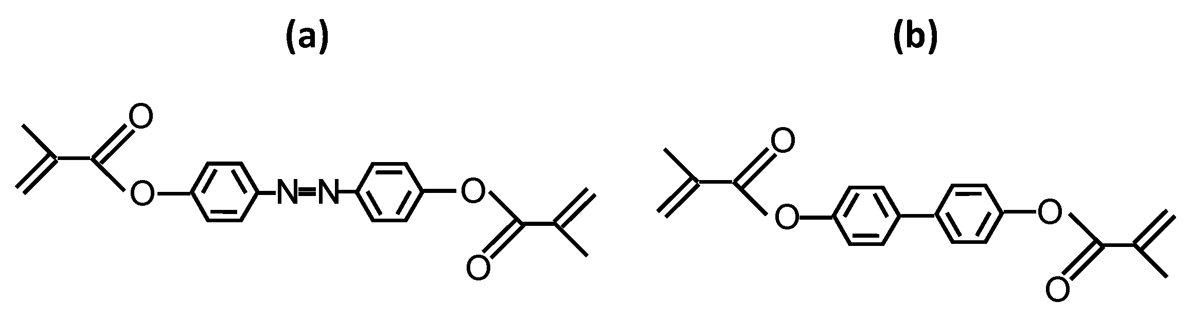
| RM | Azo-RM | Biph-RM | Biph-RM | - | 0.25 |
| Host |  | 20.0 | - | ||
 | 10.0 | - | |||
 | 10.0 | - | |||
 | 20.0 | - | |||
 | 15.0 | - | |||
| LC Mixture (PSVA Mode Cell) | VHR (%) | |
|---|---|---|
| Before UV Irradiation | After UV Irradiation | |
| I | 99.4 | 99.2 |
| II | 99.3 | 93.0 |
| III | 99.3 | 97.2 |
| Contrast Ratio | τon (ms) | τoff (ms) | |
|---|---|---|---|
| LC Mixture I | 3300:1 | 9.5 | 7.3 |
| LC Mixture II | 3300:1 | 9.9 | 6.7 |
| IV | V | Wt% (LC) | Wt%/LC | |
|---|---|---|---|---|
| Diluter | C3-CyFF-Cy-C3 | C3-HH-V | 25.0 | - |
| RM | Azo-RM | Azo-RM | - | 1.0 |
| Host |  | 25.0 | - | |
 | 10.0 | - | ||
 | 5.0 | - | ||
 | 13.0 | - | ||
 | 10.0 | - | ||
 | 10.0 | - | ||
 | 2.0 | - | ||
| LC Mixture (PI-Free IPS Cell) | VHR (%) | |
|---|---|---|
| Before UV Irradiation | After UV Irradiation | |
| IV | 99.2 | 98.8 |
| V | 99.0 | 97.3 |
Publisher’s Note: MDPI stays neutral with regard to jurisdictional claims in published maps and institutional affiliations. |
© 2022 by the authors. Licensee MDPI, Basel, Switzerland. This article is an open access article distributed under the terms and conditions of the Creative Commons Attribution (CC BY) license (https://creativecommons.org/licenses/by/4.0/).
Share and Cite
Mizusaki, M.; Okamoto, K.; Shibata, T. New Diluter Solubilized in Liquid Crystal Compounds for High Stability and Fast Response Speed Liquid Crystal Displays. Symmetry 2022, 14, 1620. https://doi.org/10.3390/sym14081620
Mizusaki M, Okamoto K, Shibata T. New Diluter Solubilized in Liquid Crystal Compounds for High Stability and Fast Response Speed Liquid Crystal Displays. Symmetry. 2022; 14(8):1620. https://doi.org/10.3390/sym14081620
Chicago/Turabian StyleMizusaki, Masanobu, Kazuo Okamoto, and Toshihiro Shibata. 2022. "New Diluter Solubilized in Liquid Crystal Compounds for High Stability and Fast Response Speed Liquid Crystal Displays" Symmetry 14, no. 8: 1620. https://doi.org/10.3390/sym14081620