Article

A Monopole UWB Antenna for WIFI 7/Bluetooth and Satellite Communication

1
School of Electrical and Information Engineering, Anhui University of Science and Technology, Huainan 232001, China
2
School of Mechanical and Electrical Engineering, Huainan Normal University, Huainan 232001, China
*
Author to whom correspondence should be addressed.
Symmetry 2022, 14(9), 1929; https://doi.org/10.3390/sym14091929
Submission received: 19 August 2022 / Revised: 13 September 2022 / Accepted: 14 September 2022 / Published: 15 September 2022

Abstract

:
In this paper, a monopole UWB broadband antenna is designed, fabricated, and measured for wireless communication networks. The initial radiator model of the proposed antenna has a short-sleeve shape, and to expand the impedance bandwidth, the right and left angles are subtracted symmetrically from the lower half of the radiator. The impedance matching is improved by etching slots in the feed line and adding L-shaped patches symmetrically on both sides of the feed line. The results show that the proposed miniaturized antenna system can cover WiFi 7(2.4–2.484 GHz, 5.15–5.35 GHz, 5.725–5.825 GHz, 5.925–7.125 GHz), 4G LTE (2.3–2.39 GHz, 2.555–2.655 GHz), 5G (4.8–5.0 GHz), X-band (7–12.4 GHz), Ku-band (10.7–14.59 GHz), and C-band uplink bands (5.925–6.425 GHz). Moreover, the antenna is found to be omnidirectional at low frequencies, with a maximum peak gain of 5.43 dBi. The antenna can be used for multi-frequency wireless communication applications.

1. Introduction

Rapid growth in global population in recent years has led to an increase in the number of various mobile devices, and these different devices communicate at different frequency bands [1]. Therefore, it is necessary to design a single terminal device that integrates multi-functional communication [2], and in this regard, a monopole UWB antenna is increasingly becoming the preferred solution [3]. For example, a monopole UWB antenna can cover multiple WiFi communication bands. In addition, other wireless communication bands, such as Bluetooth, 4G/5G, and satellite communication, should also be covered and integrated into a single terminal device. Hence, it is highly critical to study and design monopole UWB broadband antennas, in order to enable efficient modern-age communication networks.
Microstrip patch antennas have been used in many wireless systems and are very popular, due to their low profile, small size, and ease of design and fabrication [4,5,6,7]. In Ref. [8], coverage of 4G-LTE, WiMAX, WLAN, and S/C/X-bands was achieved by adding inverted-T-shaped stubs and E-shaped stubs to the ground of the etched rectangular slot. Moreover, rectangular slots were etched on the feeder to improve the impedance matching. In Refs. [9,10,11,12], microstrip multiband antennas were developed by slotting the radiator or the ground. Particularly, in Ref. [9], dual-band operation was achieved using a radiator with an etched H slot, and coverage of the three bands (2.34–2.43 GHz, 3.4–4.2 GHz, 5.09–5.6 GHz) was achieved by adding a circular ground structure on the lower surface, which had a radius of 7.9 mm and a distance of 2.8 mm from the rectangular ground. In Ref. [10], the desired frequency band was obtained by increasing the total path length, by cutting two horizontal rectangular slots at the two diagonally opposite edges of the radiator. Subsequently, in Ref. [12], a novel common ground root structure was proposed to achieve high-isolation and high-gain characteristics. In addition, single-frequency to dual-frequency transition was achieved by etching L-shaped and inverted-L-shaped slots, and the bandwidth and gain were enhanced by using an etched annular ring with a leaf-like structure. Ref. [13] designed a dual circularly polarized broadband U-slit antenna to achieve a bandwidth of 1.8–6.61 GHz and a peak gain of 3.8 dBi. In Refs. [14,15], ground slotting was utilized to achieve multi-frequency coverage, through L-shaped radiating patches on the surface. The performance of the circular polarization was improved by adding L-shaped branches in the square slot, allowing coverage for GPS, 5G, and WiFi 6E bands [14]. In [15], circularly polarized waves with different biases were generated by arranging the rectangular patches diagonally in the square slot. Ref. [16] proposed an omni-directional microstrip antenna, consisting of four shackles with different sizes and positions that were combined on the radiator, where different shackles were used to achieve different frequency bands. Ref. [17] presents a five-trap ultra-wideband antenna with WLAN and X-band suppression achieved by etching a C slot and an inverted-U slot in the Y-radiator and three symmetric C slots in the truncated floor to suppress ITU-8 bands, RN bands and WiMAX bands, ultimately achieving a bandwidth of 2–13 GHz with antenna gain of 2.1–4.51 dBi and omnidirectional co-polarized radiation in XOZ and YOZ. Ref. [18] proposed an ultra-wideband monopole antenna with three notches, and the antenna successfully isolates the WiMAX and WLAN bands by etching multiple rectangular slots in the middle of the initial radiator. In the upper part of the radiator, symmetrical three rectangles arranged at equal angles are connected by a centrally extended rectangular branch, and the notch is realized in the DSS frequency band. Ref. [19] proposed a circular microstrip patch antenna, increasing the bandwidth of the antenna by etching a crescent-shaped slot and a circular slot on the radiator and two I-shaped slots on the truncated floor. They used the embedded microstrip feeder structure to make the radiation patch perfectly match the load impedance. In Ref. [20], a J-slot-based radiator was proposed for WiFi, Wi-MAX, LTE, and C/X/Ku-band coverage, through an embedded feeder structure. Ref. [21] proposed a metamaterial-based radiator model that generated two resonance modes, achieved by etching an L-shaped slot in the radiator. In addition, branches were added on the ground to form a coupling with the radiator, which then generated a new resonance at 2.4 GHz. Refs. [22,23] realized a frequency-reconfigurable multi-frequency broadband antenna by using the diodes. Specifically, Ref. [22] studied a linear dual-polarized slot ring array antenna, where four of the diodes were arranged at equal angles for efficient switchable multi-band UWB antennas. Ref. [23] used Roger 3006 as the substrate and then used three diodes to connect five metamaterial units with the radiator to realize a dual-band broad-band antenna with low VSWR. Ref. [24] proposed a new combined Koch and Sierpinski fractal antenna, which achieved 2G/3G/4G/5G/WLAN and navigation band coverage by etching multiple triangular slots on the radiator. However, its structure was very complex and difficult to process. Ref. [25] used a carbon nanotube composite material to realize the application of a broadband millimeter wave antenna at 24–34 GHz. The antenna used a T-shaped structure as a feed network, analyzed the binary carbon nanotube antenna array, and demonstrated that the composite material outperformed copper in terms of S-parameters and efficiency. In Ref. [26], a composite material of EVA polymer and carbon mixture was used instead of a copper layer, and by optimizing the thickness of EVA and the state of carbon particles, the results showed that the radiator material used in the UWB band had better return loss performance than using copper. However, its production steps are cumbersome and require precise control of the mixture ratio.
In this paper, we propose a simple tri-band high-gain monopole UWB antenna based on an FR-4 substrate. The antenna consists of a rectangular ground, a feeder line, a modified short-sleeve-shaped patch, and a symmetrical L-shaped patch. To cover multiple frequency bands, slots were cut in the short-sleeve, and the edges were cut off. The introduced gradient structure at the strong current effectively stimulates the required working radiation mode, so that the resonant mode of the antenna transitions relatively smoothly from a resonance point to another resonance point; opening a U-shaped slot on the feeder and adding symmetrical L-shaped patches on both sides of the feeder can extend the radiation current path, thereby reducing the return loss and improving the impedance-matching performance of the antenna. The antenna proposed in this paper is small in size and low in production cost. The simulation results using HFSS software show that the antenna with a symmetrical structure can cover WiFi 7, Bluetooth, 4G/5G, and some satellite communication bands with relatively good gain.
The rest of this paper is organized as follows: Section 2 displays the proposed antenna and discusses the design evolution of the proposed antenna. Section 3 presents a parametric analysis, and Section 4 presents the current distribution of the antenna at resonance modes. Next, Section 5 shows the S-parameter results and far-field characteristics. Finally, the conclusions are given in Section 6.

2. Structure and Analysis

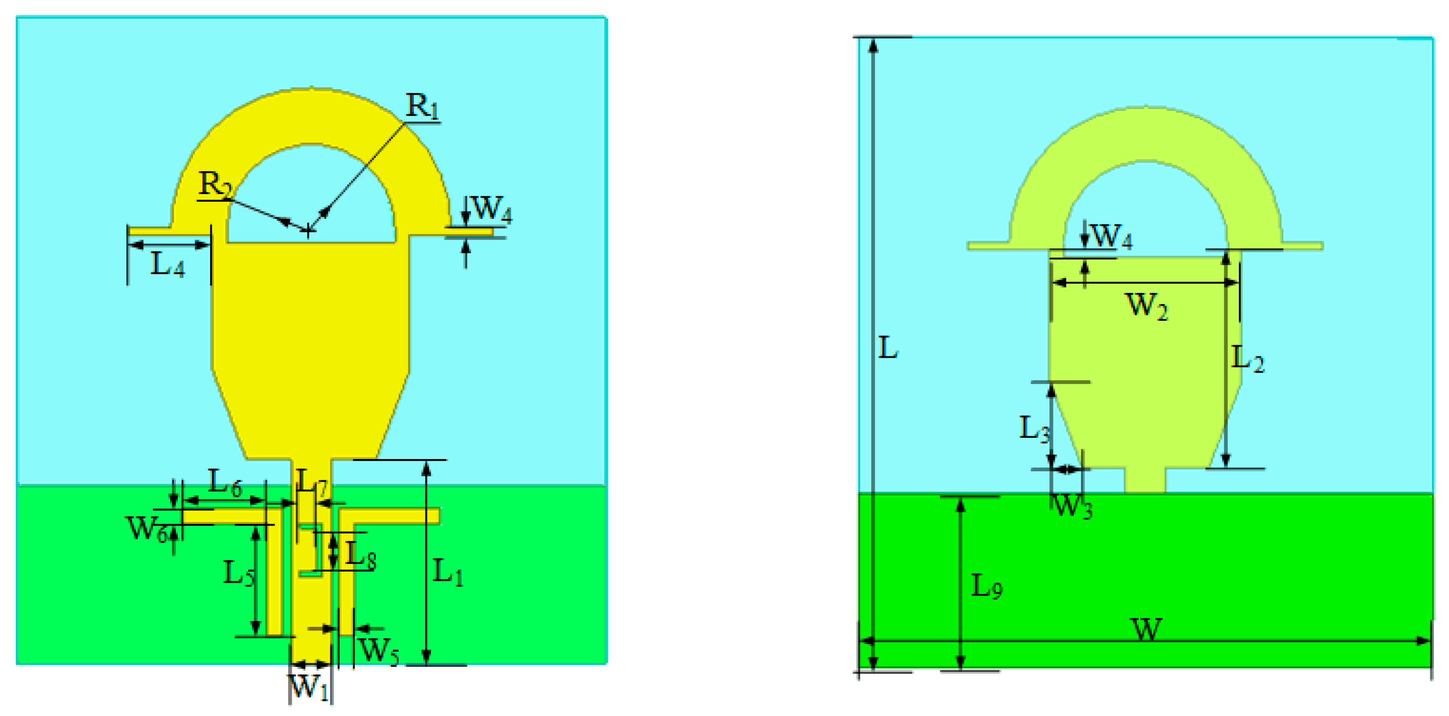
2.1. Antenna Geometry

The antenna structure design is shown in Figure 1. The antenna is feed by a 50 Ω microstrip feed line, the patch is printed on FR-4 substrate (εr = 4.4, tan δ = 0.02) using copper material, tin is sprayed on the copper to facilitate soldering of the SMA interface, and the antenna size is 46 × 42 × 1.6 mm3. The upper surface of the antenna is composed of microstrip lines and improved short-sleeved metal, while the bottom surface is a rectangular metal ground. To expand the bandwidth and improve the impedance-matching capability, this paper modifies the short-sleeve-shaped patch. By etching a semicircular slot on the radiator and subtracting the left and right corners of the lower half of the radiator, the bandwidth of the antenna is effectively improved. At the same time, in order to improve the impedance-matching effect of the antenna at high frequency (11 GHz), two L-shaped metal patches are symmetrically arranged on both sides of the microstrip line. Moreover, the simulated and measured results validate the feasibility of operation. Table 1 lists all the parameters for the proposed antenna.

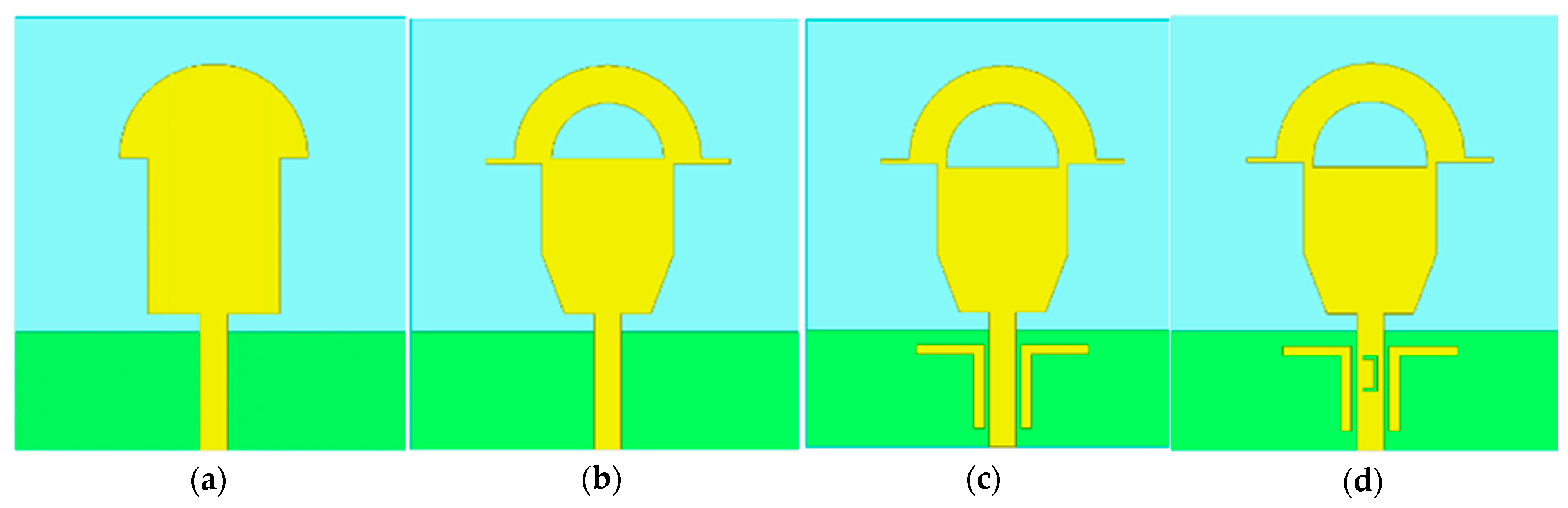
2.2. Evolution of Multi-Frequency Antennas
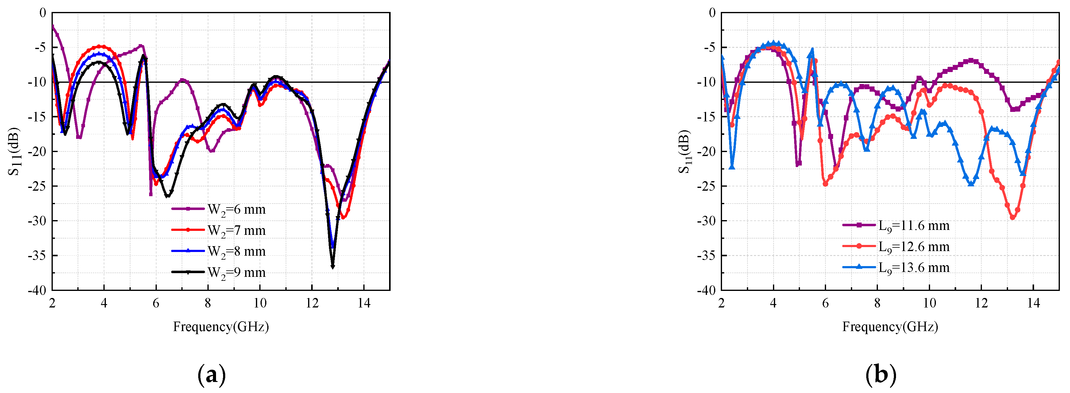
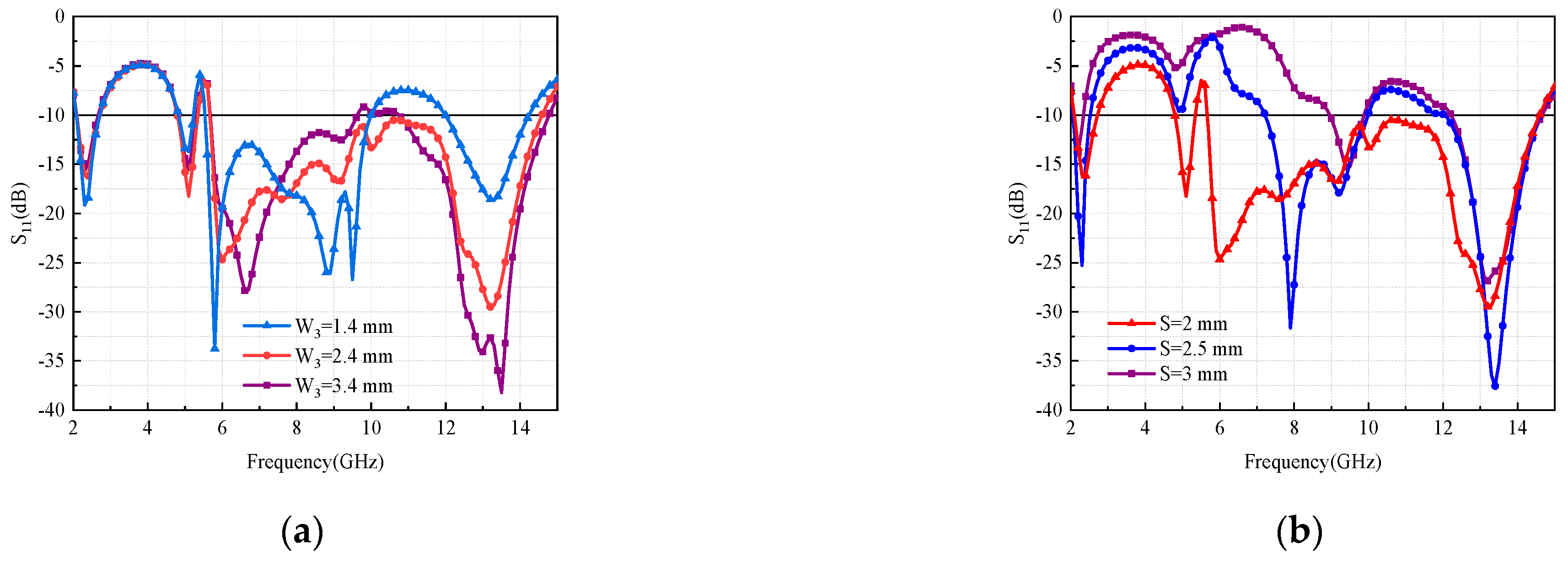
The design evolution process of the antenna is illustrated in Figure 2 and Figure 3, showing the S-parameters situation for Ant 1–Ant 4. The initial structure is shown in Figure 2a, which is composed of a rectangular ground, microstrip line, and a short-sleeve-shaped radiator, marked as Ant 1. From Figure 3, it can be seen that the simulated results for this structure achieve the coverage of three frequency bands (2.18–3.01 GHz; 4.68–9.18 GHz; 12.57–13.93 GHz). To expand the bandwidth, we etch a semicircular slot on the upper part of the initially designed short-sleeve-shaped patch for changing the current path or extending the current, add a symmetrical rectangle to the cuffs on both sides to resonate at 5.1 GHz, and subtract the two symmetrical corners from the lower part. The introduced asymptotic structure changes the strong current distribution here, allowing for better excitation of the desired modes and helping to unfold the bandwidth, as shown in Figure 2b. As is evident from the corresponding S-parameter results, the modifications to the initial short-sleeve-shaped patch increase the bandwidth by 1.6 GHz and improve the partial matching effect compared to the case of Ant 1, but the return loss is still higher than −10 dB in the 10–12 GHz range. By loading the symmetrical L-shaped patch method on both sides of the feeder, the radiation current path is extended, thereby reducing the return loss and expanding the working bandwidth. In addition, a rectangular slot is carved under the semicircular slot, again blocking the partial current and advancing the resonance frequency point from 6.8 GHz to 6.2 GHz, as shown in Figure 2c. The structure is marked as Ant 3. It can be deduced from the S-parameters of Ant2 and Ant3 that the impedance-matching performance can be improved by using symmetrical L-shaped patches on both sides of the feeder. Furthermore, cutting slots in the antenna feeder can change the current path, which can generate resonance. In this case, we inserted an inverted-U-shaped slot to block the current flow in that area, thus further improving matching around 10–13.2 GHz to make the antenna reach the standard of S11 < −10 dB in the coverage frequency band, as shown in Figure 2d. For Ant 4, adding a U-shaped slot not only improves the matching effect, but also partially increases the high-frequency bandwidth. The final antenna structure covers wide frequency bands of 2.09–2.72 GHz, 4.79–5.35 GHz, and 5.6–14.59 GHz.

3. Parametric Study

To examine the effect of different parameters of an antenna on its performance, a systematic study is carried out. The goal of this study is to identify the fabrication tolerance and, more importantly, to pinpoint the effects of antenna parameters on the bandwidth. We studied four parameters, i.e., width W2 of the middle rectangle, length L9 of the ground, base side of the triangle W3, and distance S from the L shape to the mid-point. The first two parameters are chosen because they lay the framework of the antenna structure, while the latter two parameters correspond to the evolutionary design process of the antenna.
Figure 4a demonstrates the effect of width W2 of the short-sleeve-shaped radiator on the bandwidth. It can be seen that at W2 = 6 mm, four bands are generated, but only some of them correspond to the required bands. When W2 is further widened, the covered bands tend to be the same, and for a better matching effect, W2 = 7 mm is finally chosen. As shown in Figure 4b, the length of the ground L9 has a great influence on the high-frequency band, and when L9 = 11.6 mm, the S11 in the high-frequency band of 10–12.5 GHz is higher than −10 dB, and the matching effect is not very good. Although there are more resonance points at L9 = 13.6 mm, L9 = 12.6 mm has a better matching effect, thus indicating a better choice.
Additionally, Figure 5a shows the effect of width W3 of cropping angle on the antenna bandwidth. When W3 changes from 1.4 mm to 2.4 mm, the return loss goes higher than the standard requirement of −10 dB at some high frequencies, and the bandwidth in-creases by 2.3 GHz. However, as the width continues to increase, the matching performance degrades. As displayed in Figure 5b, when the L-shaped patch moves away from the feed line, S increases, causing the bandwidth of the antenna to deteriorate significantly. Therefore, the final dimensions are selected as W3 = 2.4 mm and S = 2 mm.

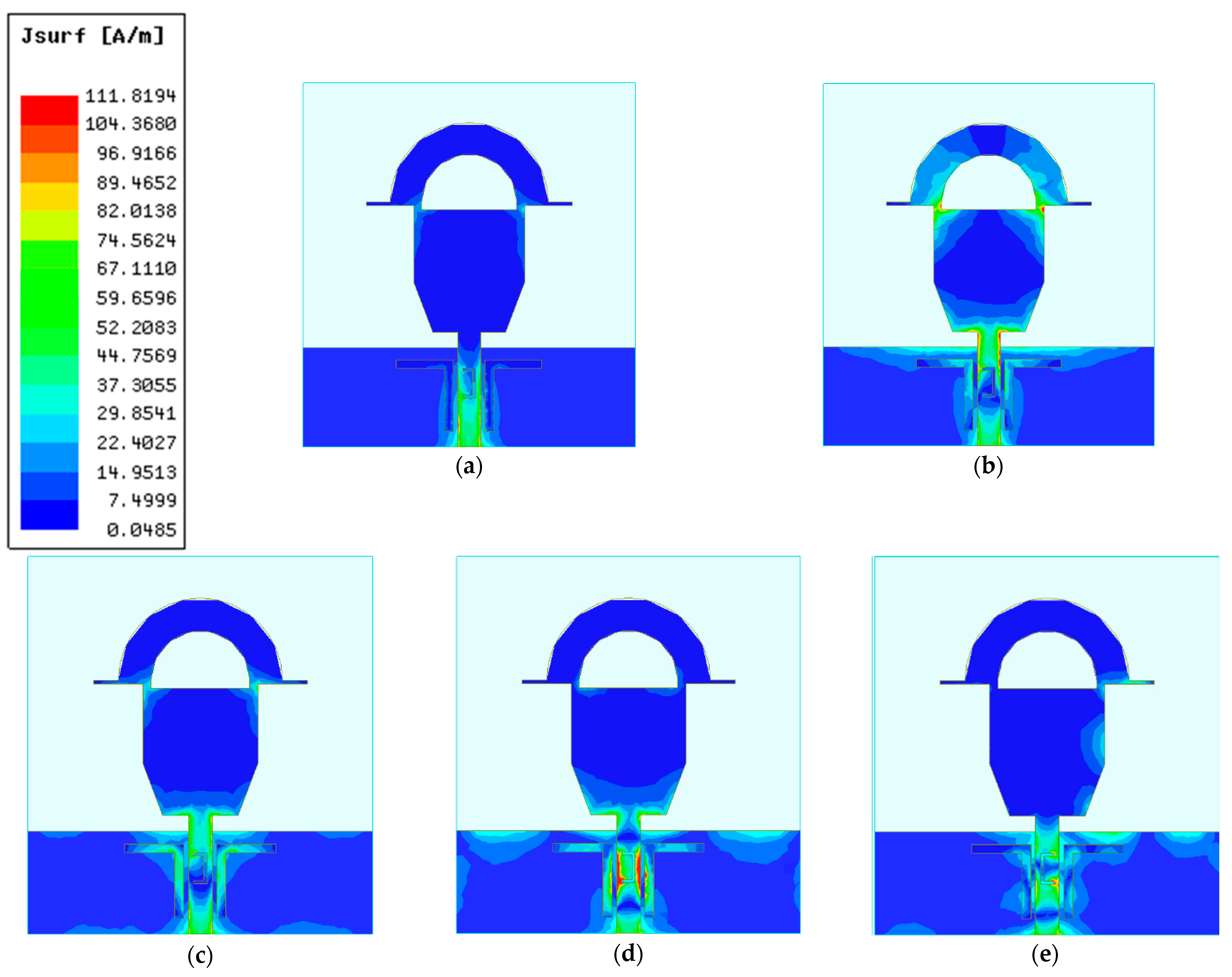
4. Surface Current Distributions

Figure 6 shows the surface current distribution of the antenna in resonant modes. It can be seen from Figure 6a,c that the surface currents at 2.4 GHz and 6 GHz are uniformly distributed, indicating that the antenna has good radiation characteristics at this frequency point. The etched semi-circular slot resonates with the added rectangular patch at 5.1 GHz, creating a current distribution at the junction of the semi-circular and rectangular, with some currents also distributed at the edges of the feeder. At 10 GHz and 13.2 GHz, the currents are mainly distributed near the U slot and the inner L patch of the feed line, from which it can be inferred that slotting on the feed line can generate resonance and adding L patches on both sides of the feed line can improve the impedance-matching performance of the antenna.

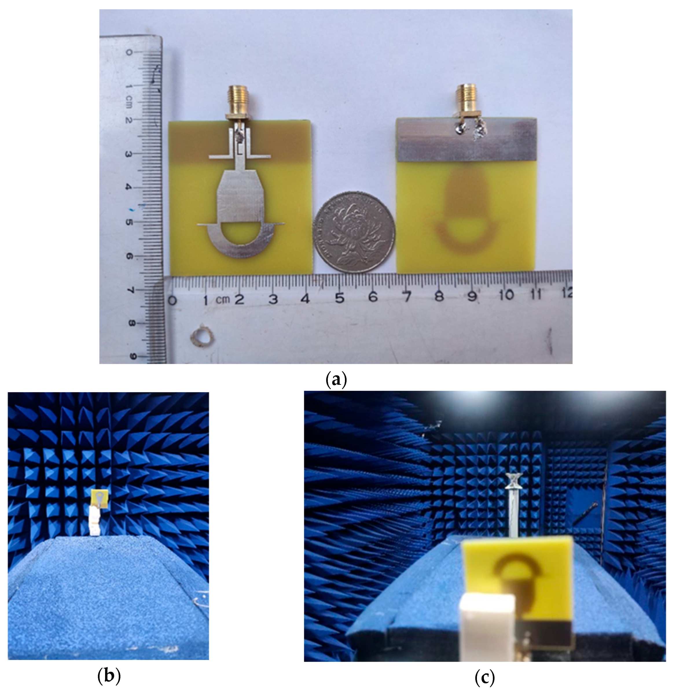
5. Measurement and Discussion

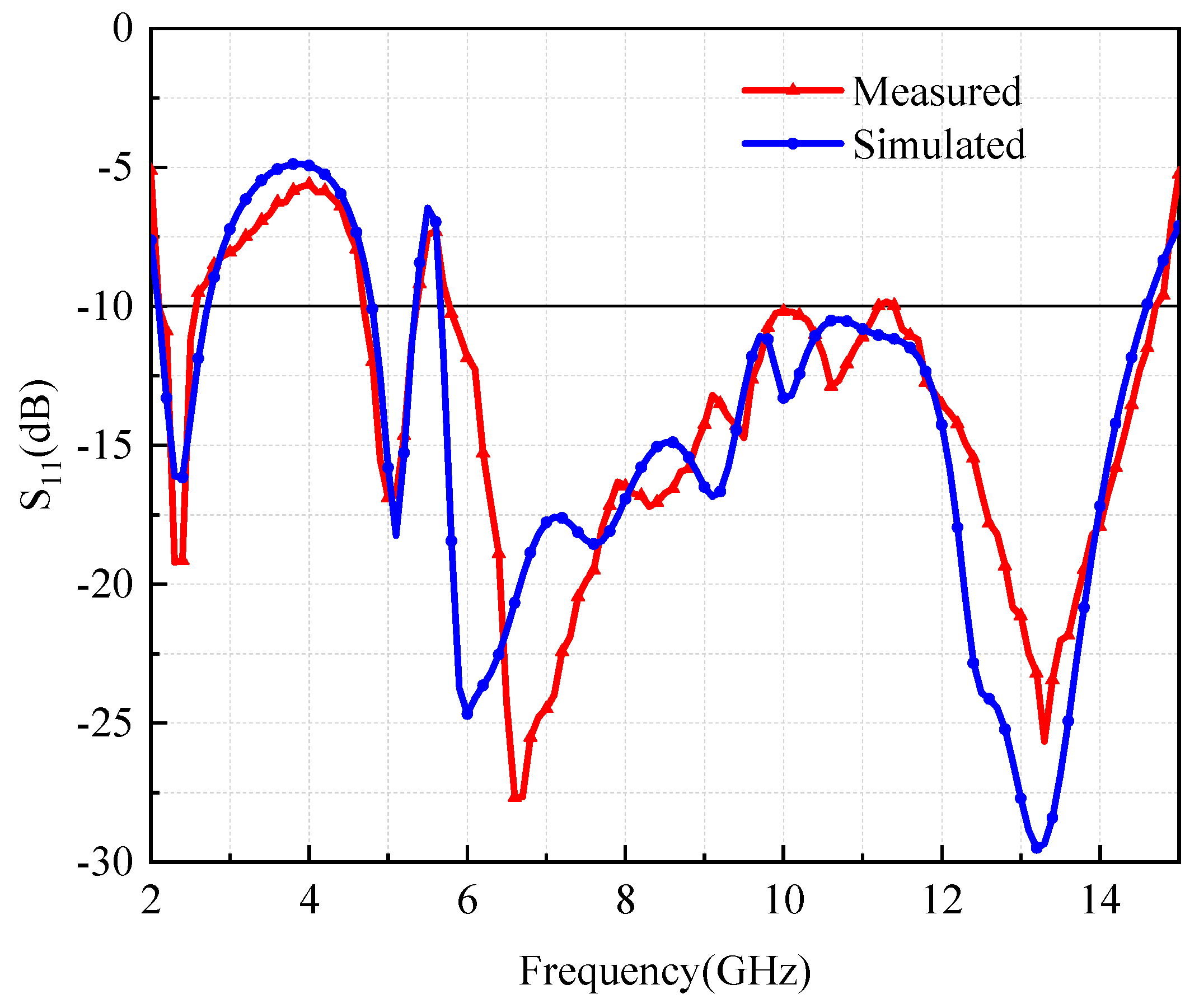
5.1. S-parameter Results

The fabricated prototype is shown in Figure 7, and the test environment for the antenna is shown in Figure 7b–c. The S-parameters were measured by AV3629D vector network analyzer.
In Figure 8, the actual measurement results show that the fabricated antenna can cover 2.12–2.55 GHz, 4.67–5.38 GHz, and 5.7–14.56 GHz bands. Notably, the small differences between the simulated and measured results are mainly due to the fabrication and welding errors, and in general, the results are very consistent. It is worthwhile to note that the proposed antenna can effectively cover newly released WiFi 7 standard, Bluetooth, 4G/5G bands, and C/X/Ku-bands.

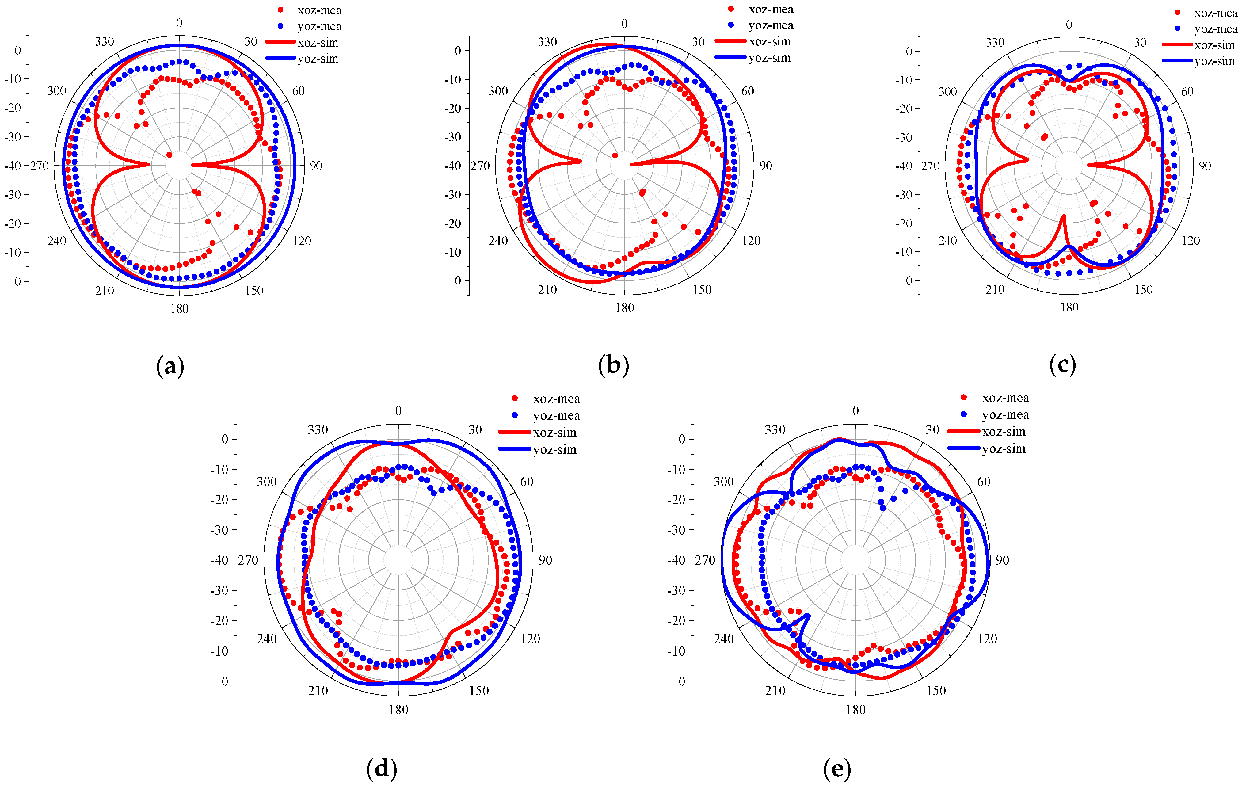
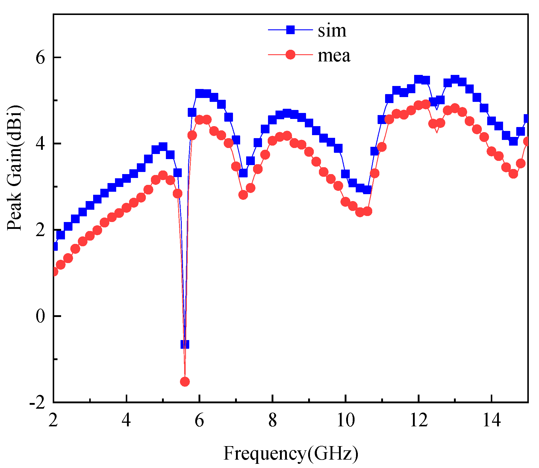
5.2. Far-Field Characteristics

The antenna was tested for its radiation patterns in an anechoic chamber, as shown in Figure 9a–e, which shows the simulated and measured xoz and yoz planes of the antenna at 2.4 GHz, 5.1 GHz, 6 GHz, 10 GHz, and 13.2 GHz. From Figure 9a–c, the antenna on the yoz surface is basically in omnidirectional radiation state for 4G/5G, Bluetooth, and WiFi 7. In addition, it can be seen from Figure 9d that the energy is mainly concentrated between 15°–60°, 120°–240° and 300°–350° of the yoz plane, while Figure 9e illustrates that the energy is mainly concentrated between 60°–110° and 240°–300° of the yoz plane, which is suitable for satellite directional communication. On the xoz surface, it can be seen from Figure 9a,b that the pattern of the antenna is “8”, and the two-way radiation effect is obvious; for Figure 9c–e, the pattern of the antenna is basically in full radiation mode.
Moreover, as shown in Figure 10, the antenna gain is between 2 and 6 dBi, with a maximum peak gain of 5.43 dBi at 13.2 GHz and a lower peak gain at 5.5–5.7 GHz. Due to the existence of the test environment and actual errors, the measured gain is lower than the simulated value. Although some of the range gain is unstable, the gain is relatively stable over the frequency band in which it operates, which can be suitable for wireless applications.
The comparison of this work in terms of size, bandwidth, and application with the designs reported in references is provided in Table 2. Although the size of the monopole UWB antenna proposed in this paper is moderate among the reported antennas, it has certain advantages in terms of band coverage and gain and will be valuable in wireless communication networks. UWB has the characteristics of high data rate, strong anti-multipath effect, and low power consumption, and it can be applied to several applications in communication. In addition, the proposed design covers all WiFi bands and can achieve omnidirectional radiation with higher gain compared to other references, which can also be applied for 4G/5G communication. Meanwhile, the last ultra-wideband can be used for satellite communication in C/X/Ku-bands. Thus, this antenna with miniaturized size allows operation at various communication bands of wireless communication networks.

6. Conclusions

In this paper, a novel, miniaturized, and easily fabricated monopole UWB antenna is proposed, which essentially has an omnidirectional radiation at low frequencies. Based on the short-sleeve-shaped patch, the antenna structure has been modified. Furthermore, by utilizing L-shaped patches on both sides of the feed line, multi-functional applications are achieved. The −10 dB bandwidths of proposed antenna are 18.42% (2.12–2.55 GHz), 14.13% (4.67–5.38 GHz), and 87.46% (5.7–14.56 GHz). The measured results show that the antenna can work in 4G/5G, WiFi (2.4G, 5G, 6G) bands, Bluetooth, X/Ku-bands, and up-stream bands of C-bands, where the peak gain in the working frequency bands is between 1.74 and 5.43 dBi. From these findings, it can be concluded that the proposed antenna can be effectively used for multi-frequency wireless communication applications.

Author Contributions

Conceptualization, Z.W.; methodology, M.W.; simulation, M.W.; validation, M.W. and W.N.; writing—review and editing, Z.W. and M.W.; data curation, W.N. All authors have read and agreed to the published version of the manuscript.

Funding

This research was funded in part by the Anhui Provincial Natural Science Foundation under grant 2108085MF200 and the Natural Science Foundation of Anhui Provincial Education Department under grant KJ2020A0307.

Institutional Review Board Statement

Not applicable.

Informed Consent Statement

Not applicable.

Data Availability Statement

The simulated and measured data used to support the findings of this study are included within the article.

Conflicts of Interest

The authors declare no conflict of interest.

References

  1. Faouri, Y.S.; Ahmad, S.; Parchin, N.O.; See, C.H.; Abd-Alhameed, R. A Novel Meander Bowtie-Shaped Antenna with Multi-Resonant and Rejection Bands for Modern 5G Communications. Electronics 2022, 11, 821. [Google Scholar] [CrossRef]
  2. Awan, W.A.; Naqvi, S.I.; Ali, W.A.E.; Hussain, N.; Iqbal, A.; Tran, H.H.; Alibakhshikenari, M.; Limiti, E. Design and Realization of a Frequency Reconfigureurable Antenna with Wide, Dual, and Single-Band Operations for Compact Sized Wireless Applications. Electronics 2021, 10, 1321. [Google Scholar] [CrossRef]
  3. Zebiri, C.; Sayad, D.; Elfergani, I.; Iqbal, A.; Mshwat, W.F.A.; Kosha, J.; Rodriguez, J.; Abd-Alhameed, R. A Compact Semi-Circular and Arc-Shaped Slot Antenna for Heterogeneous RF Front-Ends. Electronics 2019, 8, 1123. [Google Scholar] [CrossRef]
  4. Saha, H.K.; Paul, L.C.; Shezan, S.A.; Azim, R.; Al-Hadi, A.A. A 1 × 2 Rectangular Patch Array Antenna for 6 GHz WiFi Applications. In 2022 International Conference on Innovations in Science, Engineering and Technology (ICISET); IEEE: Piscataway, NJ, USA, 2022; pp. 101–105. [Google Scholar]
  5. Islam, M.K.; Rana, M.M.; Inum, R. A comparative performance analysis of inverted F antenna using different substrates. In 2015 International Conference on Electrical Engineering and Information Communication Technology (ICEEICT); IEEE: Piscataway, NJ, USA, 2015; pp. 1–4. [Google Scholar]
  6. Paul, L.C.; Sarkar, A.K.; Haque, M.A.; Miah, P.; Ghosh, P.M.; Islam, M.R. Investigation of the Dependency of an Inset Feed Rectangular Patch Antenna Parameters With the Variation of Notch Width for WiMAX Applications. In 2018 Second International Conference on Electronics, Communication and Aerospace Technology (ICECA); IEEE: Piscataway, NJ, USA, 2018; pp. 151–154. [Google Scholar]
  7. Qing, X.; Chen, Z.N. Compact Asymmetric-Slit Microstrip Antennas for Circular Polarization. IEEE Trans. Antennas Propag. 2011, 59, 285–288. [Google Scholar]
  8. Sah, B.K.; Singla, G.; Sharma, S. Design and development of enhanced bandwidth multi-frequency slotted antenna for 4G-LTE/WiMAX/WLAN and S/C/X-band applications. Int J RF Microw Comput Aided Eng. 2020, 30, e22214–e22228. [Google Scholar] [CrossRef]
  9. Kumar, A. A compact H-shaped slot triple-band microstrip antenna for WLAN and WiMAX applications. In 2016 IEEE Annual India Conference (INDICON); IEEE: Piscataway, NJ, USA, 2016; pp. 1–4. [Google Scholar]
  10. Bharadwaj, S.S.; Sipal, D.; Yadav, D.; Koul, S.K. Shorting Pin Switchable Frequency ReconFigureurable Antenna for WLAN/WiMAX Applications. In 2019 IEEE Indian Conference on Antennas and Propogation (InCAP); IEEE: Piscataway, NJ, USA, 2019; pp. 1–4. [Google Scholar]
  11. Haripriya, D.; Venkatakiran, S.; Gokulachandar, A. UWB-Mimo antenna of high isolation two elements with wlan single band-notched behavior using roger material. Mater. Today Proc. 2022, 62, 1717–1721. [Google Scholar] [CrossRef]
  12. Kumar, A.; Narayaswamy, N.K.; Kumar, H.V.; Mishra, B.; Siddique, S.A.; Dwivedi, A.K. High-isolated WiFi-2.4 GHz/LTE MIMO antenna for RF-energy harvesting applications. AEU—Int. J. Electron. Commun. 2021, 141, 153964–153975. [Google Scholar] [CrossRef]
  13. Rui, X.; Ying, L.J.; Jun, Y.J.; Kun, W.; Xiao, Q.Y. A Design of U-Shaped Slot Antenna With Broadband Dual Circularly Polarized Radiation. IEEE Trans. Antennas Propag. 2017, 65, 3217–3220. [Google Scholar]
  14. Liu, X.; Wang, H.; Yang, X.; Wang, J. Quad-Band Circular Polarized Antenna for GNSS, 5G and WIFI-6E Applications. Electronics 2022, 11, 1133. [Google Scholar] [CrossRef]
  15. Rui, X.; Ying, L.J.; Xiao, Q.Y.; Wei, Y.G.; Jun, Y.J. A Design of Triple-Wideband Triple-Sense Circularly Polarized Square Slot Antenna. IEEE Antennas Wirel. Propag. Lett. 2017, 16, 1763–1766. [Google Scholar]
  16. Zehforoosh, A.; Zehforoosh, Y. Evaluation of a novel hook-shaped multiband monopole antenna based on the AHP method. IET Commun. 2022, 16, 266–273. [Google Scholar] [CrossRef]
  17. Mewara, H.S.; Deegwal, J.K.; Sharma, M.M. A slot resonators based quintuple band-notched Y-shaped planar monopole ultra-wideband antenna. AEU—Int. J. Electron. Commun. 2018, 83, 470–478. [Google Scholar] [CrossRef]
  18. Dhasarathan, V.; Sharma, M.; Kapil, M.; Vashist, P.C.; Patel, S.K.; Nguyen, T.K. Integrated bluetooth/LTE2600 superwideband monopole antenna with triple notched (WiMAX/WLAN/DSS) band characteristics for UWB/X/Ku band wireless network applications. Wirel. Netw. 2020, 26, 2845–2855. [Google Scholar] [CrossRef]
  19. Rao, P.K.; Singh, K.J.; Mishra, R. A Circular Shaped Microstrip patch Antenna for Bluetooth/Wi-Fi/UWB/X-band Applications. In 2018 International Conference on Power Energy, Environment and Intelligent Control (PEEIC); IEEE: Piscataway, NJ, USA, 2018; pp. 638–641. [Google Scholar]
  20. Nitin, N.; Ansari, J.A.; Agrawal, N. Inset Fed J Slotted Microstrip Multiband Antenna for WiFi/LTE/WiMAX/C Band/X Band/Ku Band Applications. In 2020 IEEE Students Conference on Engineering & Systems (SCES); IEEE: Piscataway, NJ, USA, 2020; pp. 1–6. [Google Scholar]
  21. He, H.; Ying, L.; Shuai, Z.S.; Shuxi, G. Multiband Metamaterial-Loaded Monopole Antenna for WLAN/WiMAX Applications. IEEE Antennas Wirel. Propag. Lett. 2015, 14, 662–665. [Google Scholar]
  22. Mangal, J.; Gupta, N. An Annular Switchable Antenna For WiFi, WiMAX, WLAN & UWB Frequency Range Applications. In 2021 International Conference on Control, Automation, Power and Signal Processing (CAPS); IEEE: Piscataway, NJ, USA, 2021; pp. 1–4. [Google Scholar]
  23. Orugu, R.; Nesasudha, M.; Janapala, D.K. A Frequency Tunable Hexagon Shaped Antenna for 5.8 GHz-WiFi and Sub 6—5G Mobile IoT Applications. In 2021 International Conference on Computer Communication and Informatics (ICCCI); IEEE: Piscataway, NJ, USA, 2021; pp. 1–4. [Google Scholar]
  24. Zhen, Y.; Guo, Y.J.; Ying, R.X.; Hua, Z.C. A novel Koch and Sierpinski combined fractal antenna for 2G/3G/4G/5G/WLAN/navigation applications. Microw. Opt. Technol. Lett. 2017, 59, 2147–2155. [Google Scholar]
  25. Mehdipour, A.; Rosca, I.D.; Sebak, A.R.; Trueman, C.W.; Hoa, S.V. Carbon Nanotube Composites for Wideband Millimeter-Wave Antenna Applications. IEEE Trans. Antennas Propag. 2011, 10, 3572–3578. [Google Scholar] [CrossRef]
  26. Vera, E.R.; Correa, M.A.; Muno, A.G.; Ochoa, D.C.; Marin, J.S. Development of an Improved Response Ultra-Wideband Antenna Based on Conductive Adhesive of Carbon Composite. Prog. Electromagn. Res. C 2017, 79, 199–208. [Google Scholar] [CrossRef] [Green Version]
Figure 1. Geometry and parameters of the proposed antenna.
Symmetry 14 01929 g001
Figure 2. Evolution of the proposed antenna: (a) Ant 1, (b) Ant 2, (c) Ant 3, (d) Ant 4.
Symmetry 14 01929 g002
Figure 3. Simulated results for Ant 1–Ant 4.
Symmetry 14 01929 g003
Figure 4. The effects of tuning W2 and L9 on antenna performance: (a) W2, (b) L9.
Symmetry 14 01929 g004
Figure 5. The effects of tuning W3 and S on the impedance−matching performance: (a) W3, (b) S.
Symmetry 14 01929 g005
Figure 6. Current distribution at resonance point: (a) 2.4 GHz, (b) 5.1 GHz, (c) 6 GHz, (d) 10 GHz, (e) 13.2 GHz.
Symmetry 14 01929 g006
Figure 7. Fabrication and measurement: (a) front and back view of the proposed antenna; (b,c) far-field measurement in an anechoic chamber.
Symmetry 14 01929 g007
Figure 8. Simulated and measured S−Parameters.
Symmetry 14 01929 g008
Figure 9. Simulated and measured far-field patterns on XOZ and YOZ planes at: (a) 2.4 GHz, (b) 5.1 GHz, (c) 6 GHz, (d) 10 GHz, (e) 13.2 GHz.
Symmetry 14 01929 g009
Figure 10. Simulated and measured peak gain of the proposed antenna.
Symmetry 14 01929 g010
Table 1. Recommended design dimensions for antenna.
ParameterValue/mmParameterValue/mm
W42W51.1
L46L58
W12.9W61
L114.5L66.1
W214W70.4
L216.5L71.2
W32.4L83
L36.3L912.6
W40.5R110
L46R26
Table 2. Antenna parameter comparison.
Ref.Size
(mm2)
Peak Gain
(dBi)
Bandwidth
(GHz)
Applications
225 × 154.14–7.8, 3.3–4.2,
5.8–7.2, 3.3–4.2
WiMAX, WAVE
420 × 353.525.5356–7.0449WiFi (6G)
856 × 546.42.12–2.90, 4.07–4.31,
5.08–5.40, 7.90–10.19
LTE, WiMAX, WLAN (2.4G, 5G), S/C/X-band
1480 × 804.560.95–2.11, 3.05–5.39,
5.84–8.19,9.14–10.68
GNSS, 5G, WIFI-6E
1632 × 184.51.7–2.1, 2.4–2.7,
3.3–3.6, 5.0–5.7
GSM (1.8G, 1.9G), Bluetooth, WLAN (2.4G, 5.2G), WiMAX
1736 × 384.512.86–13.3Quintuple Band-Notched
(WiMAX, WLAN, ITU-8,
X-band, RN band)
1820 × 284.982.34–20Bluetooth, LTE2600, UWB
X/Ku-Band
1936 × 32/2.35–12.9Bluetooth, WiFi (2.4G, 5G),
UWB, X-Band
2057.3 × 46.9/5.0848–5.8534, 7.7244–8.9496,
10.0453–10.6162, 11.6128–12.3012,
12.7174–15.58019
WiFi (5.8G), LTE, WiMAX,
C/X/Ku-Band
216.5 × 12.93.22.3–4.0, 5–6.6WiFi (2.4G, 5.2G), WiMAX
2346 × 441.765.8–7.2WiFi (5.8G), Sub-6 5G
2480 × 544.640.85–0.96, 1.22–1.54,
1.86–2.12, 2.4–3.22,
3.69–3.97, 4.84–5.98
2G/3G/4G/5G,
WLAN (2.4G, 5G),
navigation
2641 × 41/0.609–9.105UHF/L/S/C/X band
This work46 × 425.432.12–2.55, 4.67–5.38,
5.7–14.56
WiFi 7 (2.4G, 5G, 6G), Bluetooth, 4G/5G, C/X/Ku-Band
Publisher’s Note: MDPI stays neutral with regard to jurisdictional claims in published maps and institutional affiliations.

