Article

Multi-Effects of Tunneling and Basement Excavation on Existing Pile Group

1
Department of Civil Engineering, Zhejiang University City College, Hangzhou 310015, China
2
Key Laboratory of Safe Construction and Intelligent Maintenance for Urban Shield Tunnels of Zhejiang Province, Hangzhou 310015, China
3
Zhejiang Engineering Research Center of Intelligent Urban Infrastructure, Hangzhou 310015, China
4
College of Civil Engineering and Architecture, Zhejiang University, Hangzhou 310058, China
*
Author to whom correspondence should be addressed.
Symmetry 2022, 14(9), 1928; https://doi.org/10.3390/sym14091928
Submission received: 23 June 2022 / Revised: 30 August 2022 / Accepted: 6 September 2022 / Published: 15 September 2022
(This article belongs to the Section Engineering and Materials)

Abstract

:
Tunnels and foundation pits are two separate types of excavation that are frequently used in urban settings. Excavating tunnels and foundation pits sequentially around existing pile foundations is becoming more and more prevalent as urban underground space utilization rates increase. The deformation and load transfer mechanisms of the pile group foundation under two asymmetric excavation conditions of “first tunnel, then foundation pit” and “first foundation pit, then tunnel” are studied from the perspective of the relative positions of the tunnel–pile–foundation pit based on the constant gravity model test and 3D numerical simulation. The result shows: The pile settlement of the front pile (closer to the tunnel) caused by the excavation condition of the “first foundation pit-then tunnel” is relatively larger, while the pile settlement of the rear pile (closer to the foundation pit) caused by the excavation condition of “first tunnel-then pit” is larger. The transverse tilting of the pile group caused by the excavation of the “first foundation pit-then tunnel” is relatively larger. For the front pile, the pile tip resistance generated by “first excavation-then tunnel” is about 10% greater than it was before the initial excavation, which is greater than the result of “first tunnel-then foundation pit”. For the rear pile, the pile tip resistance generated by “first excavation-then tunnel” is about 85% greater than it was before the initial excavation, which is smaller than the result of “first tunnel-then foundation pit”. The multiple excavation sequence of “tunnel first-then foundation pit” leads to a larger induced bending moment for the front pile, whereas a larger induced bending moment for the rear pile results from the multiple excavation sequence “first foundation pit-then tunnel”.

1. Introduction

The use of urban underground space by people is becoming more and more significant as urban construction picks up speed, and excavation of all urban underground engineering follows a trend of diversification, densification, and intersection. Two examples of typical urban underground developments are subway tunnels and building foundation pits. The distance between ongoing underground construction projects and existing buildings is shrinking due to the lack of available space resources. This requires that while ensuring the safety of the tunnel or foundation pit itself, the safety and normal use of the adjacent existing pile foundation buildings should also be considered. However, due to the different excavation methods of tunnels and foundation pits, the factors that cause the surrounding soil to deform are different, and the soil deformation mode and size are different, which will have different effects on the pile foundation of surrounding buildings [1,2]. The impact of various types of excavation and unloading on the current pile foundation should thus be studied because it has significant scientific and practical implications.
Numerous studies have been conducted on the impact of soil excavation on approaching pile foundations. However, the majority of these studies focus on a specific excavation technique, such as the interaction between foundation pit piles and tunnel piles. (1) Tunnel–pile interaction: Loganathan et al. [3]. examined the effect of the tunnel–pile horizontal spacing and relative vertical position on the additional responsibility of the adjacent pile foundation using model tests and discovered that when the tunnel is located near the pile end, the pile bending moment and horizontal displacement generated by excavation are greater than those of the tunnel. According to Shahin et al. [4,5], the variation of the soil layer around the tunnel is different depending on the tunnel’s deformation mode, the position of the tunnel, and the surrounding pile foundation. Then the impact on the surrounding pile foundation is also different. Since the pile foundation is being distributed around the excavated tunnel, the settlement of the soil layer above the tunnel is distributed asymmetrically along the tunnel’s center. Hong et al. [6] and Ng et al. [7] conducted experiments on the excavation of two tunnels, respectively, at different embedding depths and discovered that even though the two tunnels were excavated under the same working conditions, they were excavated sequentially, resulting in the excavation of two tunnels. The impact of tunnel excavation on the surrounding pile foundation is also different. Xu Yuanqi et al. [8] discovered that when a tunnel passes through a group of piles, the pile foundation settles significantly, but the turning angle is small. The pile foundation is transformed into a friction pile with the buried depth of the double tunnel located at the pile end. When the settlement of the pile foundation is small, but the turning angle is large, the pile foundation changes to the end-bearing pile. Lu Dechun et al. [9] carried out research on the three-dimensional disturbance characteristics of shield construction on adjacent pile foundations in the pebble stratum. They found that the location of the maximum value of the additional bending moment of the pile foundation at different pile ends is different, and the axial force of the pile body also presents different change rules; Dias and Bezuijen [10] conducted a statistical analysis of 50 engineering cases, field tests, and centrifugal tests on the interaction between tunnels and piles and found that most of the tunnel excavation did not result in pile damage. Using a three-dimensional elastic–plastic numerical model, Mroueh and Shahrour [11] and Lee and Ng [12] examined the effects of side penetration of open shield tunnels on existing single piles using finite elements and discovered that the additional deformation of the pile foundation was significant. However, both were obtained. The scope of influence is different. Wang Li and Zheng Gang [13] predicted and analyzed the impact of tunnel excavation on the surrounding pile foundation through three-dimensional numerical simulation software and found that the different excavation sequences will affect the displacement and settlement of the pile foundation. The simulation results without distinguishing the excavation sequence are larger than the results when the excavation sequence is distinguished. Soomro et al. [14] used 3D numerical simulation software to analyze the response of single piles under different excavation sequences of double-stacked tunnels. They found that the construction sequence of double-stacked tunnels with different burial depths significantly impacted the horizontal displacement and additional settlement of pile foundations. Hongsheng Qiu et al. [15] studied the influence of shield tunnel excavation on existing pile foundations through three-dimensional finite element simulation and verified the simulation results with field monitoring data. The results show that the influence of shield construction on the pile foundation is mainly concentrated in the influence range of the diameter of the two sections of the tunnel before and after the excavation face. (2) Foundation pit–pile interaction: In terms of model tests, Ong et al. [16] and Leung et al. [17] evaluated the pile foundation response of the foundation pit supporting structure in clay under both damaged and undamaged conditions and found that there is a time effect on excavation and unloading in clay. Ng et al. [18] studied the influence of supporting foundation pit excavation in dry sand on existing friction piles and focused on the influence of pile head constraints, and discovered that the excavation of the foundation pit resulted in the downward load transfer of the pile; Poulos [19,20] used finite element and boundary element to divide the effect of foundation pit excavation on the surrounding pile foundation into two stages, and studied the influence of lateral soil displacement on the pile foundation, and compiled charts for estimating additional deformations, axial forces and bending moments of pile foundations. Yang Min et al. [21] used the three-dimensional elastic–plastic finite element method to analyze the effect of factors such as the spatial effect of the foundation pit, excavation depth, stiffness of the supporting structure, stiffness of the pile foundation, the horizontal distance between the foundation pit and the pile, and pile head constraint on the additional lateral displacement and a bending moment of the pile.
When there are tunnel excavations and foundation pit excavations around buildings, most of the current research focuses on the interaction between tunnel and foundation pit [22]. There are few studies on the working conditions of simultaneous tunnel excavation and foundation pit excavation around the pile foundation of buildings. However, with the development of urban construction, this kind of working condition with two excavation methods simultaneously becomes more and more common. Therefore, it is necessary to research the simultaneous existence of the two working conditions. Shen Jianwen and Liu Li [23] carried out a project on the left and right line tunnels of a shield section of Beijing Metro Line 10 passing through the Puhui Bridge successively to analyze the effect of multiple excavations and unloading sequences on the additional responsibility of the adjacent pile foundation. On-site monitoring shows that the settlement value of the right-line tunnel after passing through the bridge pile is significantly larger than that of the left-line tunnel, indicating that the excavation sequence will have an impact on the settlement of the pile foundation; Ng and Lu [24] found that when twin tunnels with different buried depths are excavated in different sequences, the additional settlement of existing pile foundations is also significantly different through centrifugal model tests.
It can be seen that when the unloading characteristics of excavation are similar and the relative position to the pile foundation and other conditions remain unchanged, the effect of the excavation sequence on the additional responsibility of the existing pile foundation cannot be ignored.
This paper focuses on the impact of the tunnel–foundation pit excavation and unloading on the existing pile group (the tunnel and the foundation pit are located on both sides of the pile group, respectively). According to the asymmetric excavation sequence, the impact on the pile group under the action of multiple excavations and unloading of a tunnel–foundation pit is thoroughly analyzed to provide a reference for engineering design and construction using the constant gravity scale model test and compared with the three-dimensional finite element results.

2. Constant Gravity Scale Model Test

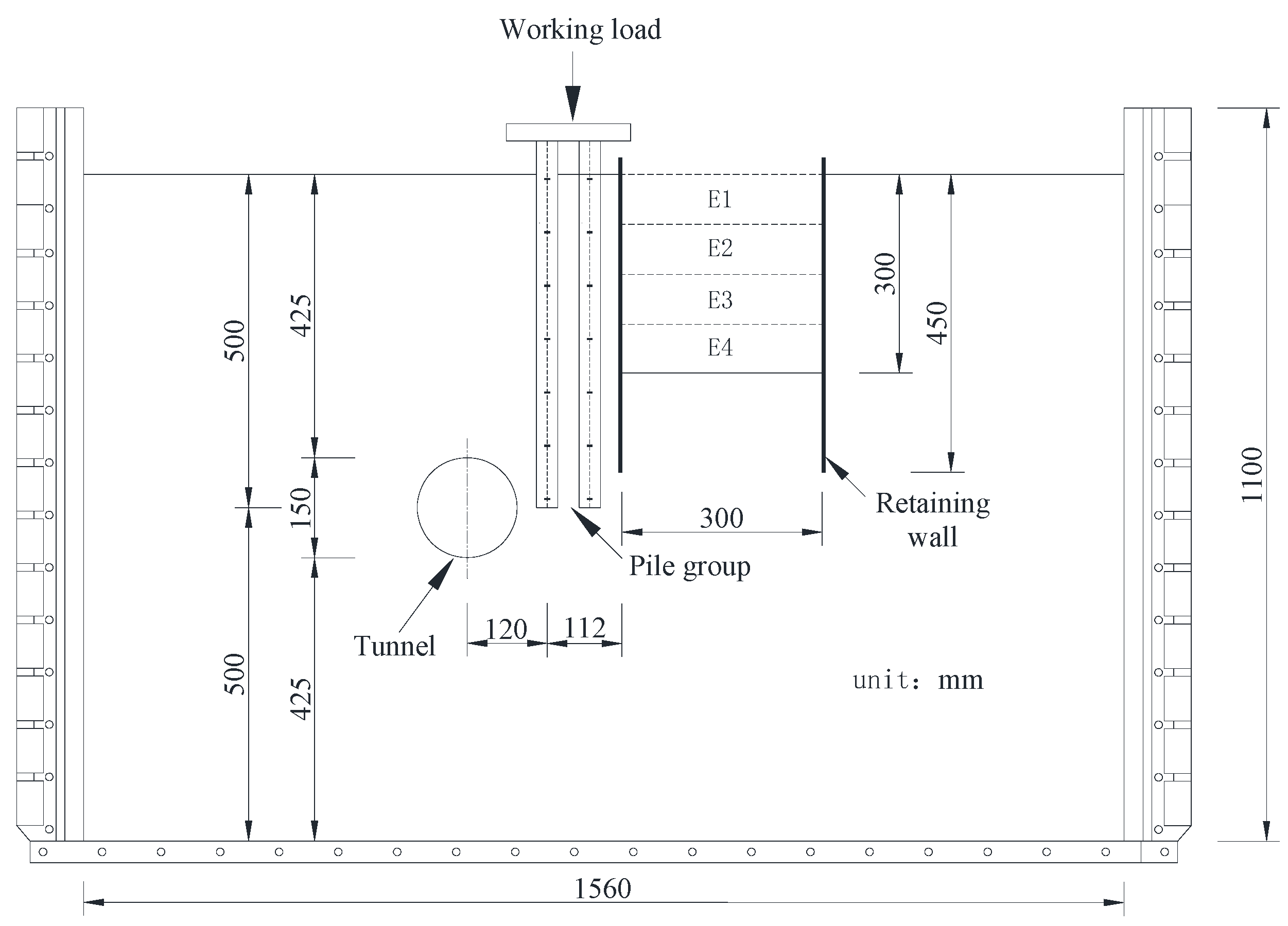
2.1. Experimental Program

This paper aims to simulate multiple excavations of tunnels and foundation pits by performing constant gravity scale model tests and studying the effect of multiple excavations and unloading sequences on adjacent pile groups’ stress and deformation characteristics. Table 1 lists the three groups of constant gravity scale model tests proposed to be conducted in this study, and the test names are defined as L, TEPG, and ETPG, respectively.
Test L is the static load test of the pile group; the letter T stands for tunnel, E stands for excavation, and PG stands for pile group. Taking TEPG as an example, this representation shows the study of the impact of multiple excavations of “first tunnel-then foundation pit” on existing pile groups.

2.2. Testing Material

Standard dry sand was selected as the soil material for this model test. The influence of particle size effect on the test should be considered in the scale model test of soil excavation and unloading. The particle size effect is related to the ratio of soil particles’ average particle size to the structure model’s size. Gui et al. [25] believed that this ratio was less than 1/20 to avoid the influence of particle size effect on the experiment.
Therefore, dry sand with a particle size of less than 1 mm was selected for the model test, and the minimum model structure size in this test was 32 mm, which satisfies the requirement that the ratio is less than 1/20, and the influence of particle size effect on the test can be ignored. The void ratio, internal friction angle, and density of the sand are respectively 0.482, 29°, and 1495 kg/m3.

2.3. Test Model Size and Material

The plane and cross-sectional layout diagrams of the constant gravity scale model test are shown in Figure 1 and Figure 2, respectively. It can be seen from the figures that the size of the test model is 1560 mm × 1200 mm × 1000 mm. According to a similar scale of 1:40, the actual project size is 62.4 m × 48 m × 44 m. The diameter of the model pile is 32 mm, and the depth of soil penetration is 500 mm. The pile group model consists of four identical single piles connected by a plexiglass cap plate, and the center distance between two adjacent piles is 64 mm. The pile close to the tunnel along the excavation direction is defined as A, and the pile close to the foundation pit is defined as B. Vertical working loads are applied by placing weights on top of the deck.
The model tunnel is arranged on the left side of the model pile foundation, with a diameter of 150 mm and a buried depth of 425 mm. The centerline of the tunnel is flush with the pile end, the center distance between the tunnel and the pile foundation is 120 mm, and the net distance is 29 mm. The model tunnel is excavated in five steps; each excavation length is 90 mm, which is, respectively, defined as T1–T5.
The model foundation pit is arranged on the right side of the model pile foundation and is supported by a cantilever. The plane size of the foundation pit is 300 mm × 300 mm, and the excavation depth is 300 mm. The depth of the support structure is 450 mm, the embedded depth is 150 mm, the insertion ratio is about 0.5, and the horizontal distance between the foundation pit and the pile is 112 mm. The foundation pit excavation uses the sand excavation method. It is planned to be excavated in four layers, and the excavation depth of each layer is 75 mm, defined as E1–E4, respectively.

2.4. In-Flight Simulation of Tunnel Excavation

This experiment uses the drainage method to simulate the volume loss caused by tunnel construction [26,27,28]. A round rubber bag was tightly wrapped around the lining, and the rubber bag was divided into five sections with steel ties. The volume loss caused by tunnel excavation was simulated by discharging the water in each section of the rubber bag in turn. Mair and Taylor [29] found that the volume loss caused by EPB shield in the sand is generally between 1% and 2%; Shirlaw et al. [30] noted that the volume loss caused by tunnel excavation was between 1% and 4% in composite formations containing sand and clay. Therefore, the volume loss of the tunnel is 2% in this experiment. This experiment simulates the excavation of the foundation pit by excavating the dry sand in the model foundation pit layer by layer.

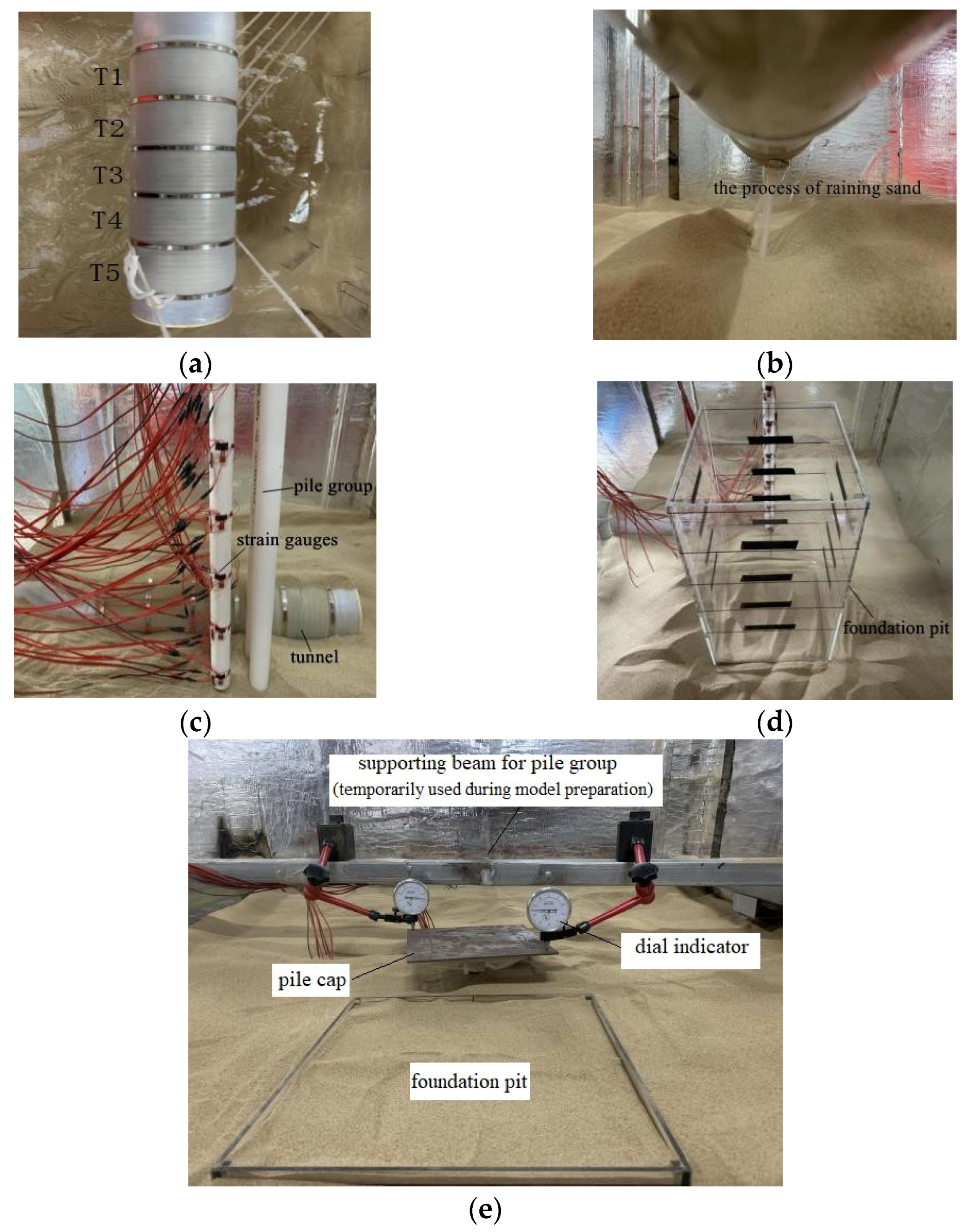
2.5. Measuring Instruments and Layout

According to the purpose of the experimental research, the measuring instrument adopts a dial indicator (range 0–10 mm) and BX120-3AA resistance strain gauge (resistance value 120 Ω, sensitivity coefficient 2.0 ± 1%, wire grid size 3 mm × 2.2 mm). The arrangement of pile bending moment and axial force strain gauge is shown in Figure 3.

2.6. Model Installation

The reference line for installing the model structure of the tunnel, pile foundation, and foundation pit can be achieved by marking the dimension scale on the inner wall of the model box; according to the tunnel volume loss, a specific amount of water is injected into the rubber bag outside the tunnel. The tunnel can be positioned and installed through the marked reference line and temporary fixing device. Then adjust the level of the tunnel and the verticality of the pile foundation with a level ruler, and lead the conduit of the rubber bag through the hole reserved at the bottom of the model box to lead out of the box, as shown in Figure 4a.
In each test, the model sandy ground was prepared by the pluvial deposition method (i.e., raining dry sand into the model box). The sand is dispersed in layers, as shown in Figure 4b, with the drop distance kept constant at 500 mm. When sand is spread to the burying position of the model piles, use the reference line to stand the model piles at the mark and spread 5 cm of sand to fix the piles, as shown in Figure 4c; then, continue to rain sand until the foundation pit support structure is buried, and also use the reference line to place the foundation pit model at the mark, as shown in Figure 4d; finally, continue to rain sand until the design elevation. After the laying is completed, the final height of the sand sample in the model box is 1000 mm, and the density is 1496.58 kg/m³, as shown in Figure 4e.

2.7. Testing Procedure

The test is divided into the following four steps:
(1) The load is applied in stages by placing weights on the top of the pile. After the loading is completed, the stability of the weights should be checked to prevent eccentricity. After each level of load is applied, the pile top settlement is less than 0.1 mm within 10 min, which can be regarded as a stable pile settlement. After the settlement is stable, the next level of loading can be performed until the pile top working load reaches the design value.
(2) The excavation of the first section of the tunnel is completed by opening the clamps on the rubber pipes leading out of the first section of the tunnel. Open the clamps of the rubber pipes leading out of the second to fifth sections of the tunnel, correspondingly once the water in the rubber bag has been drained and the data readings are stable, and continue doing so until the entire model tunnel is excavated.
(3) The dry sand in the model foundation pit is excavated layer by layer. After the dry sand drops to the specified height, the excavation of the first layer is simulated. After the data reading is stable, the next layer is excavated in sequence until the excavation of the entire foundation pit is completed.
(4) After the tunnel–foundation pit, multiple excavations are completed, the reading of the data acquisition system is completed, the model box is removed and cleaned, and the test data are processed.

3. Three-Dimensional Finite-Element Analysis

The numerical simulation method was used to investigate further the influence of the multiple excavation and unloading of the tunnel–foundation pit on the existing pile group due to the limited results obtained from the model test. The deformation and stress mechanisms of existing pile groups under the action of multiple excavations and unloading of the tunnel–foundation pit are thoroughly revealed through comparative analysis of three-dimensional numerical simulation and model test results. The finite element model of multiple excavations is established and simulated in this paper using ABAQUS [31,32].

3.1. Constitutive Model

The Mohr–Coulomb model is the most commonly used elastic–plastic constitutive model. A large number of theoretical analyses and engineering examples have proved that the Mohr–Coulomb model also has good applicability in soil excavation and unloading problems [33]. Therefore, this project adopts the Mohr–Coulomb model for calculation and analysis.

3.2. Model Parameters

The Mohr–Coulomb constitutive model is used for dry sand, and its elastic modulus, Poisson’s ratio, internal friction angle, and density are, respectively, 23 Mpa, 0.3, 29°, and 1495 kg/m3; the PVC pipe is an elastic material, and its corresponding three-dimensional model uses elastic constitutive, and its elastic modulus, Poisson’s ratio, and density are 3 Gpa, 0.38 and 1400 kg/m3, respectively. Plexiglass is also an elastic material, and its corresponding three-dimensional model uses elastic constitutive, and its elastic modulus, Poisson’s ratio, and density are 3.1 GPa, 0.2, and 1190 kg/m3, respectively. The three-dimensional numerical model of the foundation pit support is given a thickness of 4 mm.

3.3. Model Meshing and Contact Settings

Figure 5 shows the 3D numerical model established based on the scale model test. The dimension of the 3D model is set to 1560 mm × 1200 mm × 1000 mm. The numerical model is meshed by the grid function in the software, and the C3D8 solid element is used to divide the tunnel, single pile, group pile, and soil model. The S4 shell element is used to divide the foundation pit support structure, and Tie is used to bind it with the soil on the side wall of the foundation pit. The pile group model comprises 27,262 C3D8 elements, 120 S4 elements, and 31,978 nodes.

3.4. Model Boundaries and Initial Conditions

This scaled model test’s size is outside the boundary effects range. Therefore, a fixed constraint boundary can be set at the bottom of the established numerical model. A sliding constraint boundary can be set on the side to ensure that the side of the model does not move horizontally, and that the constraint direction is set to be perpendicular to the side. After the numerical model is established, the ground stress balance operation is added before the load is applied to the top of the model pile. Initial stress is applied to the model at the interface of the load module of the software, so as to complete the stress balance of the three-dimensional model. The initial displacement of the model is zero before the load is applied.

3.5. Numerical Modelling Procedure

(1) A three-dimensional numerical model, as shown in Figure 5, is established, and the initial boundary conditions of the numerical model are set to complete the initial stress balance [34,35];
(2) Apply the same working load as the model test on the top of the model pile to ensure that the numerical simulation conditions are the same as the model test;
(3) The “life and death element” function in the software is used to remove the soil element set of the first section of the tunnel, and the DCM method (Cheng et al. [36]; Ma et al. [37]) is used to simulate the excavation of the first section by imposing displacement conditions on the tunnel boundary. Repeat this step, and continue excavating in sections until all the excavation of the tunnel is completed;
(4) Setup binding constraints between the foundation pit supporting structure and the soil on the sidewall of the foundation pit. Using the “life and death unit” function in the software, remove the soil unit set of the first layer of the foundation pit, then repeat this step and continue excavating in layers until the excavation of the foundation pit has been completed;
(5) The software post-processing module analyzes and processes the results once it completes the three-dimensional numerical model calculation.

4. Interpretation of Measured and Computed Results

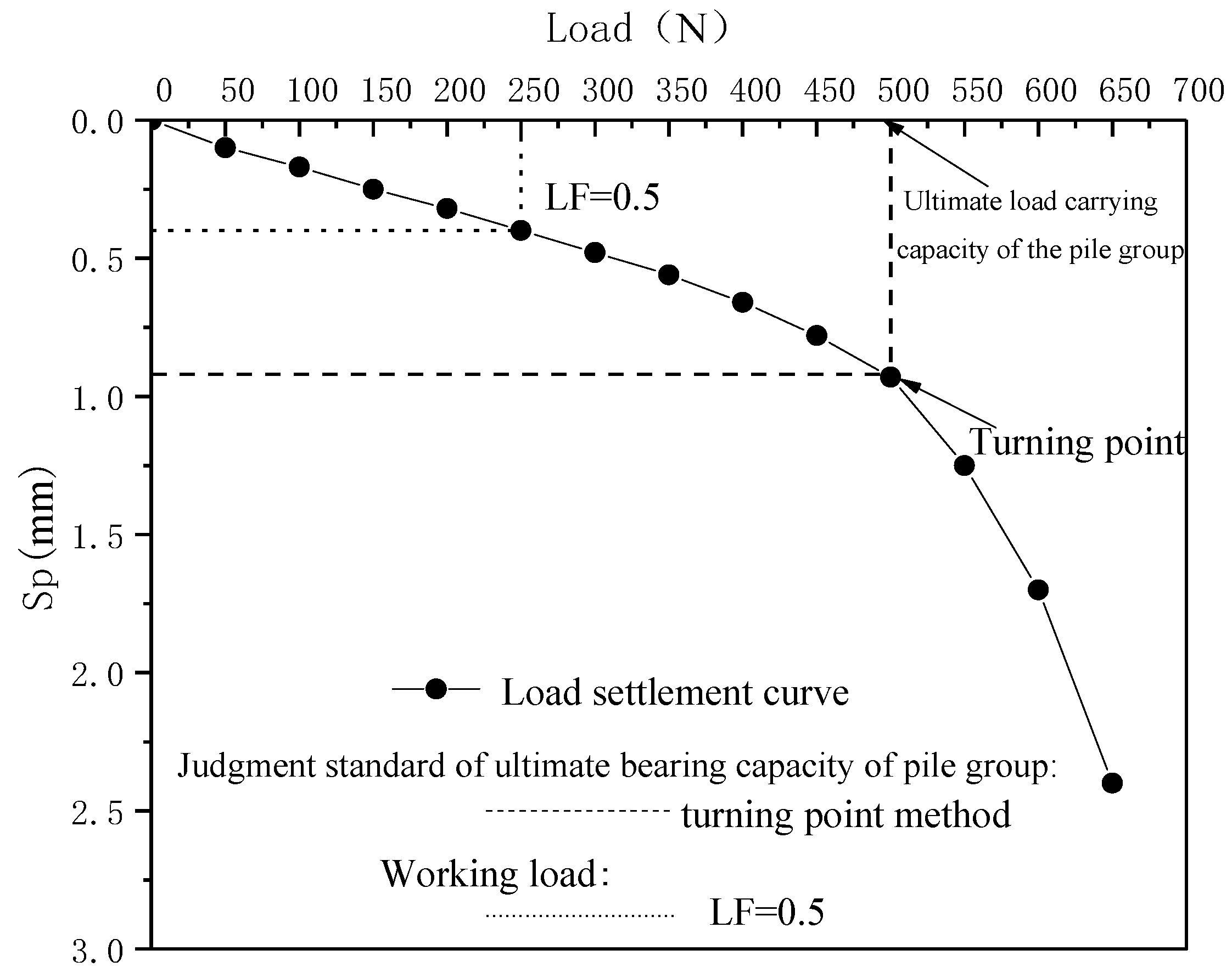
4.1. Determination of the Axial Load-Bearing Capacity of the Pile Group

The pile group, static load test, was conducted in this paper considering the pile group effect, and the load–settlement curve shown in Figure 6 was obtained. According to the turning point method of the load–settlement curve (P–S curve), the ultimate load of the pile group is 500 N. For the subsequent TEPG and ETPG tests, 250 N can be used as the working load at the top of the pile, and the load factor of the pile foundation is 0.5.

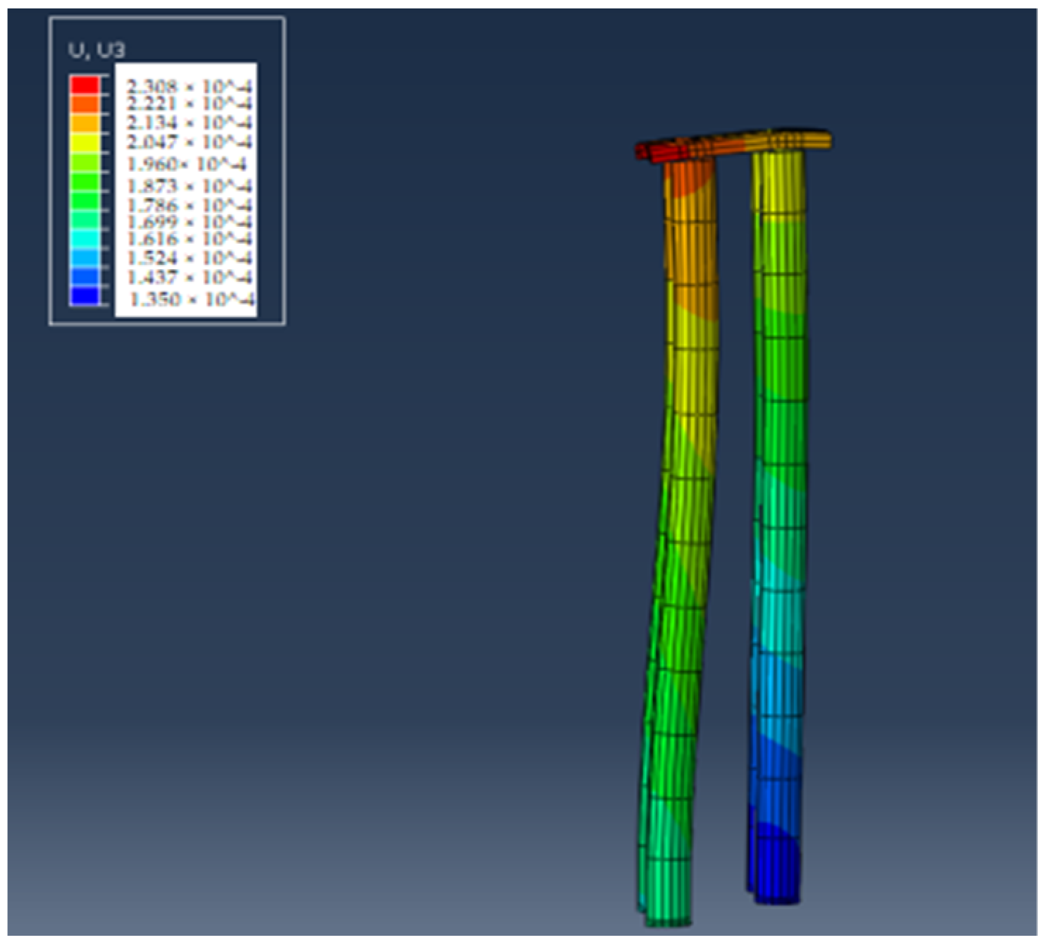
4.2. Settlement of Pile Group

Figure 7a shows that the settlement of pile A in the TEPG test was 0.46% dp and 0.63% dp during the excavation stage of T1 and T2, respectively; the settlement of pile A suddenly increased during the T3 excavation stage of the tunnel crossing, reaching 2.13% dp; the settlement of T4 and T5 stages was 1.33% dp and 0.58% dp, respectively; finally, the accumulated settlement of pile A caused by the tunnel excavation first was 5.13% dp. The cumulative settlement of pile A caused by tunnel excavation in the ETPG test was 5.69% dp, which was about 11% higher than the cumulative settlement caused by the tunnel excavation in the TEPG test of 5.13% dp. The reason may be that the load distribution forms of pile A before tunnel excavation in the two tests are different.
Figure 7b shows that in the TEPG test, the settlement of pile A caused by the excavation of the foundation pit increases continuously. In stages E1 and E2, the settlement of pile A was 0.1% dp; in stages E3 and E4, the settlement was 0.32% dp; finally, the accumulated settlement of pile A caused by the excavation of the foundation pit was 0.42% dp. The variation trend of the net pile settlement of pile A caused by foundation pit excavation in ETPG is consistent with that in TEPG. However, the cumulative settlement of A pile caused by the foundation pit excavation in ETPG was 0.58% dp, about 34% higher than the settlement in TEPG.
It is clear from the comparison that the numerical simulation results of pile A are similar to the results of the model test; that is, the settlement gradually increases with the tunnel excavation and reaches the maximum value when the tunnel passes through the pile foundation; the settlement of the pile top increases linearly with the excavation of the foundation pit. However, the settlement of pile A predicted by numerical simulation is lower than the experimental results. When the tunnel excavation is completed, the settlement of TEPG and ETPG are underestimated by 13% and 10%, respectively, compared with the experimental results; when the foundation pit excavation is completed, the settlement of TEPG and ETPG are underestimated by 6% and 7%, respectively, compared with the experimental results.
Figure 8a shows that in the test TEPG, settlements of 0.4% dp, 0.41% dp, and 0.57% dp occurred, respectively, during the excavation stages of T1, T2, and T3 when the tunnel passed through the B pile; the settlement increased significantly in T4 stage, reaching 1.6% dp; the settlement of T5 was 1.02% dp. Finally, the cumulative settlement of pile B caused by the tunnel excavation in TEPG was 4.03% dp. Compared with the A pile, the cumulative settlement was reduced by about 21%. The reason may be that the distance between the B pile and the tunnel is greater than that of the A pile. The soil around the B pile is less disturbed, resulting in settlement of the A pile being greater than that of the B pile. Because the B pile is affected by the “shielding effect” of the A pile, the disturbance of the soil around the B pile is delayed, which leads to a significant increase in the top settlement of the B pile only in the T4 stage.
The net settlement of pile B caused by tunnel excavation in ETPG has a similar change rule to that of TEPG. However, the cumulative settlement of pile B top caused by tunnel excavation in ETPG is 3.74% dp, which is about 7% lower than the cumulative settlement in TEPG of 4.03% dp. The reason may be that the foundation pit had been excavated before the tunnel excavation in ETPG, which leads to the different distribution of the pile body load of pile B before the tunnel excavation in the two groups of tests.
Figure 8b shows that in the TEPG test, the settlements of pile B in E1, E2, E3, and E4 stages were 0.29% dp, 0.16% dp, 0.15% dp, and 0.18% dp, respectively. The settlement of pile B reached the maximum during the E1 stage, and the accumulated settlement was 0.78% dp. Compared with pile A, the total settlement increases by about 82%. The reason may be that the relative distance between pile B and the foundation pit is smaller than that of pile A, and the soil around pile B is greatly disturbed, resulting in a settlement greater than that of pile A. The pile B generates an upward binding force, and the binding force further increases with the differential settlement, which in turn leads to a decrease in the increase in settlement of the B pile after the E1 stage. In addition, due to the “restraint action” of the pile cap, pile B produces an upward restraint force increasing with the differential settlement, which in turn leads to a decline of the settlement increase after the E1 stage. The variation law of the net pile top settlement of the B pile caused by the excavation of the foundation pit in ETPG is consistent with TEPG. However, the cumulative settlement of pile B caused by the foundation pit excavation in ETPG is 0.7% dp, which is about 10% lower than the cumulative settlement caused by the tunnel excavation in TEPG of 0.78% dp. It can be seen from the comparison that the numerical simulation results are similar to the model test results; that is, the settlement of pile B gradually increases with the tunnel excavation. However, the settlement reaches the maximum during the period when the tunnel passes through the pile foundation (T3 stage), which is different from the test result in that the settlement reaches the maximum during the T4 stage.
The settlement of the pile increases linearly with the excavation of the foundation pit. In the end, the settlement of pile B predicted by numerical simulation is lower than the experimental results. After the tunnel excavation was completed, the numerical simulation results of TEPG and ETPG were underestimated by 21% and 18%, respectively, compared with the experimental results; after the excavation of the foundation pit, the numerical simulation results of TEPG and ETPG underestimated the experimental results by 12% and 11%, respectively.

4.3. Transverse Tilting of Pile Cap

It can be seen from Figure 9 that due to the influence of the “restraint effect” and the “shielding effect,” the pile group will produce an uneven settlement, which will lead to the transverse tilting of the pile cap.
The trends of induced tilting in the test TEPG and ETPG are consistent; the tilting increases gradually during the TI and T2 stages and increases significantly in the T3 stage. During the T4 and T5 stages, the tilting rebounded and decreased. The trend of “increase–decrease” can be easily observed. The trends of induced tilting caused by the excavation of the foundation pit in the test TEPG and ETPG are also consistent; that is, the tilting gradually decreases during the E1 and E2 stages, then slightly increases during the E3 stage. In the subsequent E4 stage, the tilting decreased again. The trend of “decrease–increase–decrease” can be seen.
In Figure 10, we can see the finite element simulation diagram of transverse tilting of the pile cap.The results are similar to the model test results; tilting increases gradually with the tunnel excavation and continues to increase until the tunnel is far away from the pile group. This differs from the test results because tilting decreases when the tunnel moves away from the pile group. With the foundation pit’s excavation, the pile group’s tilting gradually decreases, which is consistent with the test results. In the end, the inclination of the pile group predicted by the numerical simulation was larger than that of the test results. “The numerical simulation results of the experimental TEPG and ETPG were overestimated by 28% and 9%, respectively, compared with the experimental results. Due to complex characteristics, the pile–soil interface cannot be reflected in the numerical simulation.

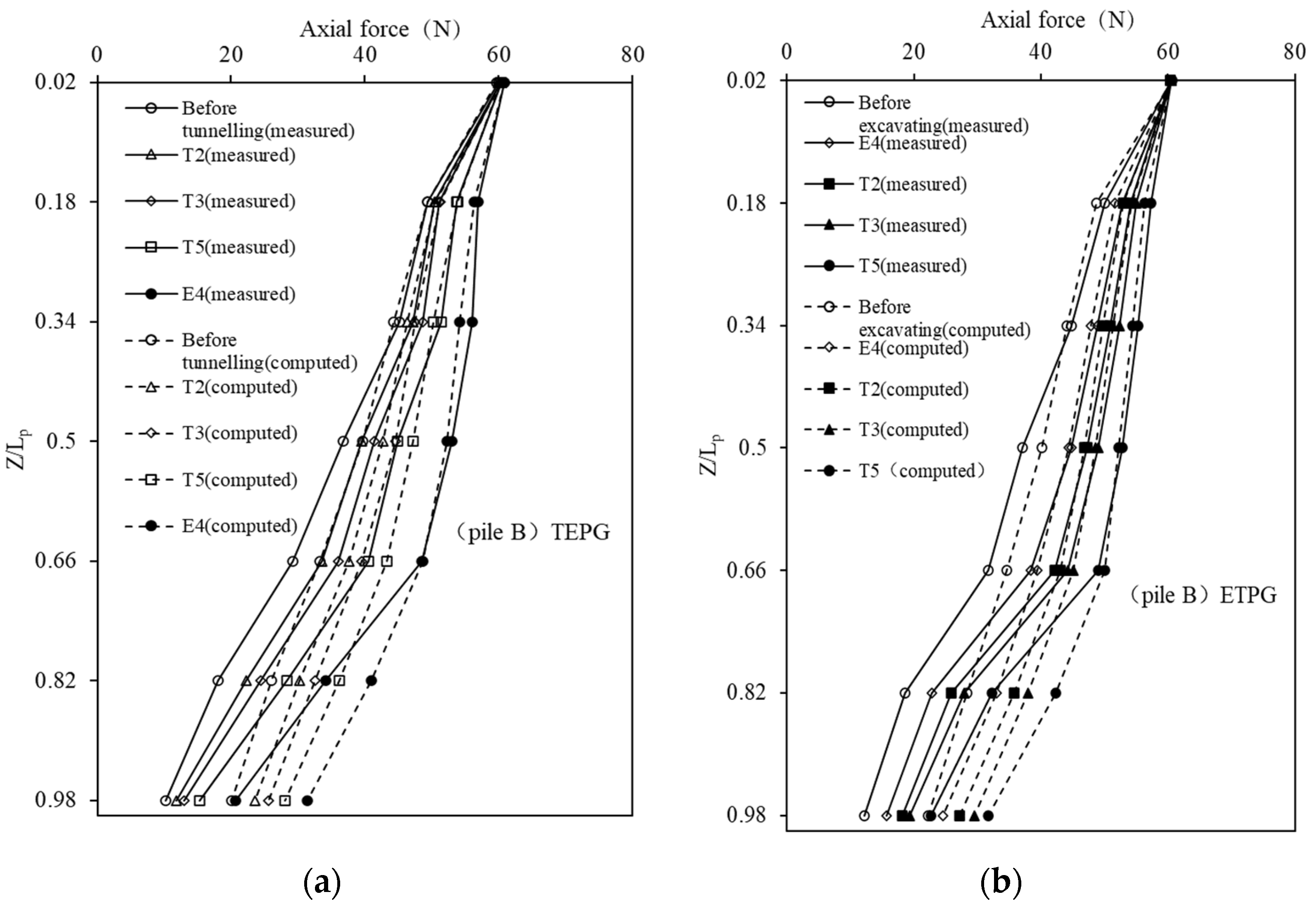
4.4. Axial Load Distribution

It can be seen from Figure 11a that in the test TEPG, the axial force of pile A caused by tunnel excavation has a trend of “increase–decrease–increase”. The tip resistance was reduced by 18% compared to before excavation, indicating that the tunnel excavation close to the pile tip resulted in the upward load transfer process, which is consistent with Ng et al. [38] based on the centrifugal model test. The subsequent excavation of the foundation pit caused a “single increase” of the axial force of pile A. The tip resistance was increased by about 32% compared with that before the excavation, indicating that the excavation of the foundation pit caused the downward load transfer along the pile body; compared with the initial distribution state before excavation, the axial force of pile A after multiple excavations had increased, and the tip resistance had increased by about 8% compared with that before the tunnel excavation. The cumulative increase was 0.02 Qa, which indicates that in TEPG, the multiple excavations lead to the downward load transfer of pile A; that is, the load sharing ratio of the tip resistance increases.
From Figure 11b, it can be observed that in ETPG, the axial force of pile A during the excavation of the foundation pit or tunnel has a similar variation pattern to that of the TEPG. However, the tip resistance caused by the excavation of the foundation pit in ETPG increased by 43% compared with that before the excavation, which was 11% greater than that in TEPG; the tip resistance caused by tunnel excavation in ETPG is 23% lower than that before excavation, and it is also larger than the result of TEPG which is 18%. After all the excavation is completed, the axial force of pile A increases compared with that before the initial excavation, and the final tip resistance increases by about 10%, which is also 2% larger than the result of the test TEPG.
To sum up, the multiple excavation sequence of “first foundation pit-second tunnel” will cause more upper loads to move down to the pile end, which also explains this excavation sequence is more conducive to ensuring the safety of pile A in the pile group from another perspective.
Comparing Figure 11a,b, it can be seen that no matter what excavation sequence is adopted, the results of numerical simulation prediction underestimate the axial force of the upper section of pile A and overestimate the axial force of the lower section of pile A. Still, the overall variation law is consistent with the test results; that is to say, with the excavation of the tunnel, the axial force of the pile has a changing law of “first increase–then decrease–then increase”. With the excavation of the foundation pit, the axial force of the pile shows a trend of “single increase”.
In the test ETPG, the excavation of the foundation pit caused the tip resistance of pile A to increase by 16%, which was 7% greater than the test TEPG. In the test TEPG, the tunnel excavation caused the tip resistance of pile A to decrease by 12%, which is 2% smaller than the result of the test ETPG. In the end, the cumulative increase in the tip resistance of pile A in the test ETPG is larger than that of the TEPG, which is consistent with the test results; that is, the excavation method of “first tunnel-then foundation pit” is more conducive to ensuring the safety of pile A in the pile group.
It can be seen from Figure 12a that under the excavation sequence of “tunnel first-foundation pit second” in the test TEPG, the axial force of pile B caused by the first tunnel excavation shows a “single increase” trend. The tip resistance increased by 49% compared with that before the excavation, indicating that the tunnel excavation close to the pile toe caused the downward load transfer of pile B, which was opposite to pile A; the subsequent excavation of the foundation pit caused a “single increase” of the axial force of pile B, and the tip resistance was increased by about 35% compared with that before the excavation; compared with the initial distribution state before excavation, the axial force of pile B after multiple excavations has increased, and the final tip resistance has increased by about 102% compared with that before the tunnel excavation. The cumulative increase is 0.17 Qa, indicating that part of the working load is transferred from pile A to pile B.
It can be seen from Figure 12b that under the excavation sequence of “foundation pit first-tunnel second” in the test ETPG, the axial force of pile B shows a similar variation law to that of the test TEPG. However, the excavation of the foundation pit in the test ETPG resulted in a 29% increase in the tip resistance compared with that before the excavation, which was smaller than the tip resistance produced by the excavation of the foundation pit in the test TEPG; in the test ETPG, the excavation of the tunnel resulted in a 44% increase in the tip resistance compared with that before the excavation, which was also smaller than that of the test TEPG. After all the excavation is completed, the axial force is generally higher than before the initial excavation, and the final tip resistance increases by about 85%. In comparison, the result of TEPG is 102%.
To sum up, the multiple excavation sequence of “first tunnel-then foundation pit” will cause more upper loads of pile B to move down to the pile toe, which also shows that the “first foundation pit-then tunnel” excavation method is more conducive to ensuring the safety of the pile B in the pile group from another perspective.
Comparing Figure 12a,b, it can be seen that no matter which excavation sequence is adopted, the numerical simulation results underestimate the axial force of the upper section of the pile and overestimate the axial force of the lower section. Still, the overall data results are consistent with the test results; that is, with the excavation of the tunnel and foundation pit, the axial force of the pile body presents a “single increase” trend. In the test ETPG, the excavation of the foundation pit caused a 10% increase in the tip resistance, while the tunnel excavation caused an increase of 29% in the tip resistance. In the test TEPG, the tip resistance caused by the tunnel excavation increased by 40%, while the excavation of the foundation pit caused a 12% increase in the tip resistance.
In the end, the cumulative increase in the tip resistance caused by “tunnel first-then foundation pit” is greater than that of “foundation pit first-then a tunnel,” which is consistent with the test results, that is, the excavation method of “foundation pit first-then tunnel” is more conducive to ensuring the safety of pile B in the pile group.

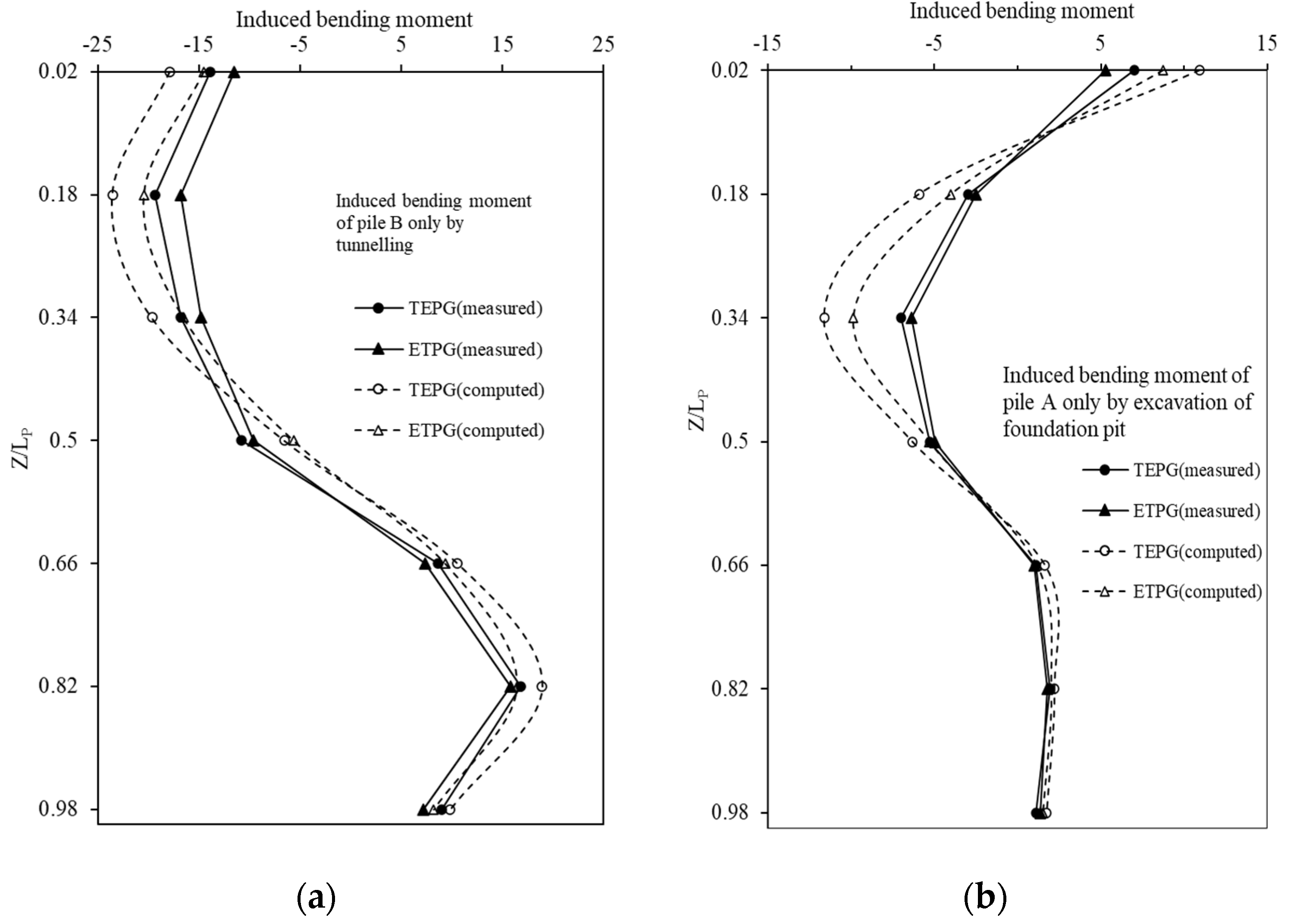
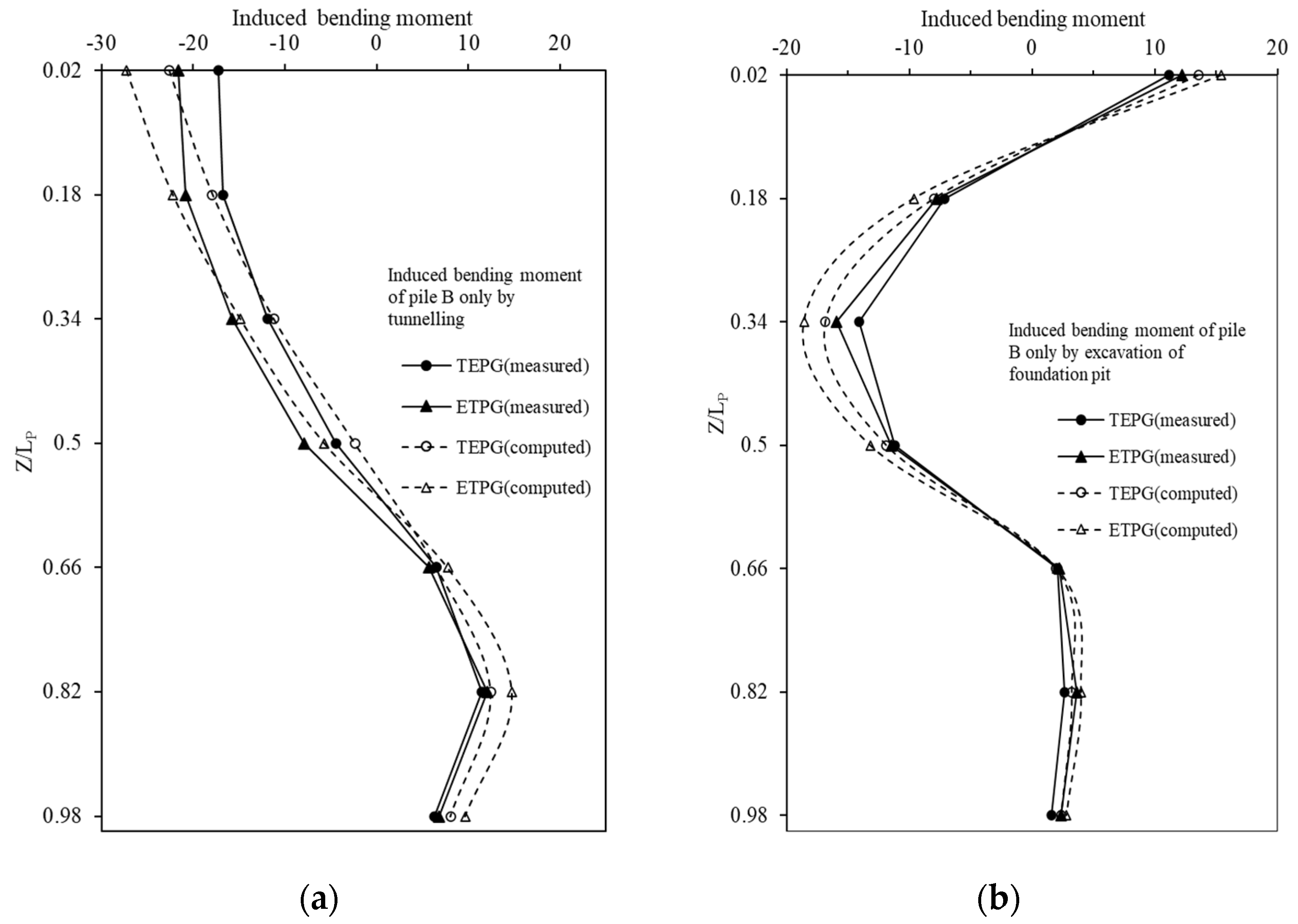
4.5. Bending Moment Distributions

It can be seen from Figure 13a that the tunnel excavation in the test TEPG resulted in a negative bending moment in the upper half of pile A and a positive bending moment in the lower half of the pile. The negative bending moment near the pile head was −13.93 N∙m, and the magnitude of the maximum positive bending moment at z/Lp = 0.18 was 19.35 N∙m. In the test TEPG, when the foundation pit excavation is completed, the negative bending moment near the pile head is reduced to −6.89 N∙m, 51% lower than the tunnel excavation. However, the excavation of the foundation pit induces a 23% increase in the negative bending moment of the upper part of the pile and a 12% increase in the positive bending moment of the lower part of the pile. In summary, in the test TEPG, the excavation-induced large bending moments at z/Lp = 0.34, z/Lp = 0.82, and near the pile head should be paid attention to.
As shown in Figure 13b, the ETPG test, the net bending moment of the pile body caused by the excavation of the foundation pit shows a similar trend to that of TEPG; however, the negative bending moment near the pile head in ETPG is 25% smaller than that in TEPG. The variation trend of the net bending moment of pile A caused by the tunnel excavation in the test ETPG is consistent with that of TEPG. However, the negative bending moment near the pile head in ETPG is 17% smaller than that in TEPG.
After all, excavation is completed, the negative bending moment of the upper part of the pile and the positive bending moment of the lower part of the pile increase due to the cumulative effect. The magnitude of maximum negative bending moment at z/Lp = 0.02, z/Lp = 0.34, and z/Lp = 0.82 in ETPG is 9%, 11%, and 6% smaller than that of TEPG, respectively. The reason may be that the horizontal displacements of the piles in the two tests are different, reducing different cumulative bending moments of pile A. The multiple “first tunnel-later excavation” sequences lead to the A-pillars producing larger piles bending moment. The multiple excavation sequences in TEPG reduced the larger bending moment for pile A.
Figure 14a shows that the bending moment distribution of pile B induced by tunnel excavation in TEPG is similar to that of pile A. However, the magnitude of the maximum negative bending moment near the head of pile B is −17.26 N∙m, which is 11% smaller than that of pile A. The maximum positive bending moment at z/Lp = 0.82 of pile B is 11.45 N∙m, which is 32% smaller than the maximum positive bending moment of pile A.
Analyzing the reason, it may be that pile B is subjected to a stronger “restraint action” by the pile cap than that of pile A, and because the ability to limit horizontal displacement and rotation is enhanced, the bending moment near the head of pile B is greater than that of pile A. However, the relative distance between pile B and the tunnel is greater than that of pile A, and the horizontal displacement of pile B is small, resulting in a smaller bending moment of the B pile than that of pile A. When the foundation pit is excavated, the negative bending moment of the upper part of pile B and the positive bending moment of the lower part increase to −25.98 N∙m and 14.13 N∙m, respectively; however, the bending moment near the pile head is attenuated, and the attenuation is larger than that of pile A. The reason may also be that pile B is subjected to a stronger “restraint” of the pile cap than that of pile A, resulting in a larger positive bending moment to offset part of the negative bending moment near the pile head. Simultaneously, the negative bending moment of the upper part of the pile and the positive bending moment of the lower part of the pile is promoted.
Figure 14b shows that in the test ETPG, the trend of net bending moment of the pile caused by foundation pit excavation is consistent with that of TEPG. The maximum negative bending moment in ETPG is 13% larger than that of TEPG at z/Lp = 0.34, and the maximum positive bending moment in ETPG is 36% larger than that of TEPG at z/Lp = 0.82. The net bending moment of the pile caused by tunnel excavation in ETPG has a variation trend that is consistent with TEPG; however, the magnitude of the negative bending moment near the pile head caused by the tunnel excavation in ETPG is 24% larger than that of TEPG, and the maximum positive bending moment at z/Lp = 0.82 in ETPG is 5% larger than that of TEPG. After all the excavation is completed, the negative bending moment of the upper part of the pile and the positive bending moment of the lower part of the pile both increase due to the cumulative effect. The maximum negative bending moment at z/Lp = 0.02 and z/Lp = 0.82 in ETPG is 53% and 11% larger than that of TEPG. This is because the horizontal displacement of the piles caused by the two excavation sequences is different, and the multiple excavation sequence in ETPG results in a larger bending moment for pile B.
During the tunnel excavation, the calculation results of numerical simulation show that the bending moment of pile A caused by the tunnel in TEPG is larger than that of ETPG, which has a similar trend to the test results, as shown in Figure 15. However, the numerical calculation results overestimate the negative bending moment at z/Lp = 0.02–0.34 in the upper section of pile A and the positive bending moment at z/Lp = 0.82 in the lower section while underestimating the negative bending moment at z/Lp = 0.5 in the middle section of the pile. Similarly, during the foundation pit excavation, the numerical calculation results also show that the net bending moment of pile A caused by the foundation pit in TEPG is larger than that of ETPG, which has a similar trend to the test results; however, the positive bending moment near the head of pile A and the negative bending moment at z/Lp = 0.18–0.34 are overestimated.
During tunnel excavation, the numerical calculation results show that the bending moment of pile B caused by the tunnel in TEPG is smaller than that of ETPG, which has a similar trend to the test results, as shown in Figure 16; however, the negative bending moment at z/Lp = 0.02 of pile B and the positive bending moment at z/Lp = 0.82 are overestimated; similarly, during the excavation of the foundation pit, the numerical calculation results also show that the net bending moment of pile B caused by foundation pit in TEPG is smaller than that of ETPG, which has a similar trend to the test results; however, the positive bending moment near the head of pile B and the negative bending moment at z/Lp = 0.34 were overestimated.

5. Summary and Conclusions

The influence of excavation sequence on pile A and pile B in the pile group is analyzed using the test results of TEPG and ETPG in constant gravity scale model tests, compared with the results predicted by the three-dimensional numerical model, taking into account the two asymmetric excavation sequences of “tunnel first-then foundation pit” and “first foundation pit-then a tunnel”. This analysis provides a theoretical foundation for selecting an appropriate excavation scheme in practice. The main conclusions are as follows:
1.
Because of the influence of the “restraint effect” and “shielding effect” of the pile group, uneven settlement of piles A and B are induced. The settlement of pile A caused by multiple excavations in ETPG is relatively larger, while the settlement of pile B caused by multiple excavations in TEPG is relatively larger. The settlements of piles A and B predicted by numerical simulation are smaller than the test results.
2.
The transverse tilting of the pile group caused by multiple excavations in TEPG and ETPG were 0.37% and 0.92%, respectively, which means the tilting of the pile group in ETPG is relatively larger. The tilting predicted by the numerical simulation is larger than the test result. It increases when the tunnel is far away from the pile group, which is different from the test result; however, the overall trend is consistent with the experimental result.
3.
For pile A, the tip resistance caused by multiple excavations in ETPG is about 10% higher than before the initial excavation, which is 2% more than the test result in TEPG. This shows that the excavation sequences in TEPG are more conducive to ensuring the safety of pile A in the pile group; for pile B, the tip resistance induced in ETPG is about 85% larger than that before the initial excavation, which is 17% smaller than the test result in TEPG. It shows that the excavation sequences in ETPG are more conducive to ensuring the safety of pile B in the pile group. The results of numerical simulation prediction underestimate the axial force of the upper part of piles A and B and overestimate the axial force of the lower part of the pile, regardless of the chosen excavation sequence.
4.
The multiple excavation sequence of “tunnel first-foundation pit second” leads to a larger bending moment for pile A, while the excavation sequence of “foundation pit first-tunnel second” induces a larger bending moment for pile B due to the “restraint effect” of the cap and the influence of the distance between the excavation area and the pile foundation. The prediction results of numerical simulation during tunnel excavation overestimate the maximum negative bending moment of the pile, while the overall variation trend is consistent with the test results.
5.
The soil material used in this test is sand. Due to the poor permeability of cohesive soil, the unloading of soil excavation has a time effect, and the adjacent pile foundation is not stable after the completion of excavation, with a high degree of time and space dependence. At present, there are few relevant studies in the existing model tests, and subsequent studies can be carried out in clay. This test has not analyzed the influence of the size of the foundation pit and tunnel diameter on pile groups. Model tests can be carried out to further study the additional response of pile foundations caused by the change of geometric characteristics of foundation pit and tunnel.

Author Contributions

Supervision, writing—review and editing, H.D.; conceptualization, methodology, writing—original draft preparation, Y.T.; software, validation, formal analysis, Y.T. and G.W.; data curation, investigation, X.W.; project administration, X.L. All authors have read and agreed to the published version of the manuscript.

Funding

National Natural Science Foundation of China (Grant No.52009122), Zhejiang Provincial Natural Science Foundation of China (Grant No.LQ21E090002), Research and Development Foundation of Zhejiang University City College (J-202222), Project funded by China Postdoctoral Science Foundation (2022M712724) is acknowledged.

Institutional Review Board Statement

Not applicable.

Informed Consent Statement

Not applicable.

Data Availability Statement

Not applicable.

Conflicts of Interest

The authors declare no conflict of interest.

References

  1. Guo, W.D.; Ghee, E.H. A preliminary investigation into the effect of axial load on piles subjected to soil movement. In Proceedings of the International Symposium on Frontiers in Offshore Geotechnics, Perth, Australia, 19–21 September 2005. [Google Scholar]
  2. Lei, G.H.; Ng, C.W.W.; Rigby, D.B. Stress and displacement around an elastic artificial rectangular hole. J. Eng. Mech. 2001, 127, 880–890. [Google Scholar] [CrossRef]
  3. Loganathan, N.; Poulos, H.G.; Stewart, D.P. Centrifuge model testing of tunnelling-induced ground and pile deformations. Géotechnique 2000, 50, 283–294. [Google Scholar] [CrossRef]
  4. Shahin, H.M.; Nakai, T.; Zhang, F.; Kikumoto, M.; Nakahara, E. Behavior of ground and response of existing foundation due to tunneling. Soils Found. 2011, 51, 395–409. [Google Scholar] [CrossRef]
  5. Shahin, H.M.; Nakahara, E.; Nagata, M. Behaviors of ground and existing structures due to circular tunneling. In Proceedings of the 17th International Conference on Soil Mechanics and Geotechnical Engineering, Alexandria, Egypt, 5–9 October 2009; IOS Press: Amsterdam, The Netherlands, 2009; pp. 1786–1789. [Google Scholar]
  6. Hong, Y.; Soomro, M.A.; Ng, C.W.W. Settlement and load transfer mechanism of pile group due to side-by-side twin tunnelling. Comput. Geotech. 2015, 64, 105–119. [Google Scholar] [CrossRef]
  7. Ng, C.W.W.; Hong, Y.; Soomro, M.A. Effects of piggyback twin tunnelling on a pile group:3D centrifuge tests and numerical modelling. Geotechnique 2015, 65, 38–51. [Google Scholar] [CrossRef]
  8. Xu, Y.Q.; Shan, Z.G.; Gan, P.L.; Liu, S.M.; Zhang, Z.Z.; Hou, Y.M. Influence of side-by-side twin tunneling on an existing pile group. Chin. J. Rock Mech. Eng. 2021, 40, 2935–2944. [Google Scholar]
  9. Lu, D.C.; Ding, C.; Lin, Q.T.; Du, X.L. Experimental study on three⁃dimensional effects of shield tunnel excavation on adjacent pile. J. Disaster Prev. Mitig. Eng. 2022, 42, 732–741. [Google Scholar]
  10. Dias, T.G.S.; Bezuijen, A. Data analysis of pile tunnel interaction. J. Geotech. Geoenviron. Eng. 2015, 141, 4015051. [Google Scholar] [CrossRef]
  11. Mroueh, H.; Shahrour, I. Three-dimensional finite element analysis of the interaction between tunneling and pile foundations. Int. J. Numer. Anal. Methods Geomech. 2002, 26, 217–230. [Google Scholar] [CrossRef]
  12. Lee, G.T.K.; Ng, C.W.W. Effects of advancing open face tunneling on an existing loaded pile. J. Geotech. Geoenviron. Eng. 2005, 131, 193–201. [Google Scholar] [CrossRef]
  13. Wang, L.; Zheng, G. Research on effects of shield driven tunneling on adjacent single friction-pile. Rock Soil Mech. 2011, 32, 621–627. [Google Scholar]
  14. Soomro, M.A.; Mangia, N.; Xiong, H.; Kumar, M.; Mangnejo, D.A. Centrifuge and Numerical Modelling of Stress Transfer Mechanisms and Settlement of Pile Group due to Twin Stacked Tunnelling with Different Construction Sequences. Comput. Geotech. 2020, 121, 103449. [Google Scholar] [CrossRef]
  15. Qiu, H.S.; Wang, Z.; Ayasrah, M.; Fu, C.B.; Gang, L. Numerical study on the reinforcement measures of tunneling on adjacent piles. Symmetry 2022, 14, 288. [Google Scholar] [CrossRef]
  16. Ong, D.E.; Leung, C.E.; Chow, K.Y. Pile behavior due to excavation-induced soil movement in clay. I: Stable wall. J. Geotech. Geoenviron. Eng. 2006, 132, 36–44. [Google Scholar] [CrossRef]
  17. Leung, C.F.; Ong, D.E.; Chow, K.Y. Pile behavior due to excavation-induced soil movement in clay. II: Collapsed wall. J. Geotech. Geoenviron. Eng. 2006, 132, 45–53. [Google Scholar] [CrossRef]
  18. Ng, C.W.W.; Wei, J.; Poulos, H.; Poulos, H.; Liu, H. Effects of multipropped excavation on an adjacent floating pile. J. Geotech. Geoenviron. Eng. 2017, 143, 4017021. [Google Scholar] [CrossRef]
  19. Poulos, H.G.; Chen, L.T. Pile response due to excavation-induced lateral soil movement. J. Geotech. Geoenviron. Eng. 1997, 123, 94–99. [Google Scholar] [CrossRef]
  20. Poulos, H.G.; Chen, L.T. Pile response due to unsupported excavation-induced lateral soil movement. Can. Geotech. J. 1996, 33, 670–677. [Google Scholar] [CrossRef]
  21. Yang, M.; Zhou, H.B.; Yang, H. Numerical analysis of pile response due to unsupported excavation-induced lateral soil movement. China Civ. Eng. J. 2005, 38, 91–96. [Google Scholar]
  22. Ng, C.W.W.; Shi, J.W.; Hong, Y. Three-dimensional centrifuge modelling of basement excavation effects on an existing tunnel in dry sand. Can. Geotech. J. 2013, 50, 874–888. [Google Scholar] [CrossRef]
  23. Shen, J.W.; Liu, L. Numerical analysis and field monitoring for studying effects of shield tunnelling on nearby piles. Rock Soil Mech. 2015, 36, 709–714. [Google Scholar]
  24. Ng, C.W.W.; Lu, H. Effects of the construction sequence of twin tunnels at different depths on an existing pile. Can. Geotech. J. 2014, 51, 173–183. [Google Scholar] [CrossRef]
  25. Gui, M.; Bolton, M.D.; Garnier, J.; Corte, J.F.; Renzi, R. Guidelines for cone penetration tests in sand. In Proceedings of the International Conference on Centrifuge 98, Tokyo, Japan, 23–25 September 1998; Balkema, A.A., Ed.; CRC Press: Leiden, The Netherlands, 1998; pp. 155–160. [Google Scholar]
  26. Jacobszs, W. The Effects of Tunneling on Piled Foundations. Ph.D. Thesis, University of Cambridge, Cambridge, UK, 2002. [Google Scholar]
  27. Zhang, Z.G.; Fang, L.; Ma, S.K.; Lv, X.L.; Shi, M.Z.; Lu, Y.H. Model test study on ground settlement caused by excavation of quasi-rectangular tunnels in soft soils. Mod. Tunn. Technol. 2020, 57, 762–771. [Google Scholar]
  28. Shao, Y.; Liu, Y.; Jinag, J.; Ma, S.K.; Xie, Q. Metro Operation-Induced Dynamic Response of Foundation Soil for Different Degrees of Consolidation. Mod. Tunn. Technol. 2018, 55, 133–139+147. [Google Scholar]
  29. Mair, R.J.; Taylor, R.N. Bored tunnelling in the urban environment. State-of-the-art report and theme lecture. In Proceedings of the 14th International Conference on Soil Mechanics and Foundation Engineering, Hamburg, Germany, 6–12 September 1997; pp. 2353–2385. [Google Scholar]
  30. Shirlaw, J.N.; Ong, J.C.W.; Rosser, H.B.; Tan, C.G.; Osborne, N.H.; Heslop, P.E. Local settlements and sinkholes due to EPB tunnelling. Geotech. Eng. 2003, 156, 193–211. [Google Scholar] [CrossRef]
  31. Giner, E.; Sukumar, N.; Tarancón, J.E.; Fuenmayor, F.J. An Abaqus implementation of the extended finite element method. Eng. Fract. Mech. 2009, 76, 347–368. [Google Scholar] [CrossRef]
  32. Simulia, D.C.S. Abaqus 6.11. Anal. User′s Man. 2011, 16, 32–134. [Google Scholar]
  33. Ng, C.W.W.; Sun, H.S.; Lei, G.H.; Shi, J.W.; Mašín, D. Ability of three different soil constitutive models to predict a tunnel′s response to basement excavation. Can. Geotech. J. 2015, 52, 1685–1698. [Google Scholar] [CrossRef]
  34. Hu, C.M.; Yuan, Y.L.; Mei, Y.; Qian, W.F.; Ye, Z.W. Initial Geo-Stress Balance Method for the Finite-Element Model Using the Stratum-Structure Method. Mod. Tunn. Technol. 2018, 55, 76–86. [Google Scholar]
  35. Yang, J.Y.; Lei, J.B.; Zou, Y.Q.; Li, Z.Z.; Wan, M.H.; Yue, T.S.; Pratik, K.B. Preliminary analysis on initial stress balance method of composite foundation with cap pile based on ABAQUS. J. Nanchang Hangkong Univ. Nat. Sci. 2017, 31, 73–78. [Google Scholar]
  36. Cheng, C.Y.; Dasari, G.R.; Chow, Y.K.; Leung, C.F. Finite element analysis of tunnel-soil-pile interaction using displacement controlled model. Tunn. Undergr. Space Technol. 2007, 22, 450–466. [Google Scholar] [CrossRef]
  37. Ma, S.K.; Shao, Y.; Liu, Y.; Jiang, J.; Fan, X.L. Responses of pipeline to side-by-side twin tunnelling at different depths: 3D centrifuge tests and numerical modelling. Tunn. Undergr. Space Technol. 2017, 66, 157–173. [Google Scholar] [CrossRef]
  38. Ng, C.W.W.; Lu, H.; Peng, S.Y. Three-dimensional centrifuge modelling of the effects of twin tunnelling on an existing pile. Tunn. Undergr. Space Technol. 2013, 35, 189–199. [Google Scholar] [CrossRef]
Figure 1. (a) Plan view of Centrifuge model; (b) arrangement of LVDTs (Linear Variable Differential Transformers) on the pile cap.
Symmetry 14 01928 g001
Figure 2. Elevation of constant gravity model.
Symmetry 14 01928 g002
Figure 3. Layout drawing of pile group bending moment and axial strain gauge. (a) Schematic diagram. (b) Physical diagram.
Symmetry 14 01928 g003
Figure 4. Model preparation and installation. (a) Tunnel model diagram. (b) Soil material. (c) Pile model diagram. (d) Foundation pit diagram. (e) Displacement measuring device.
Symmetry 14 01928 g004
Figure 5. Three-dimensional numerical model.
Symmetry 14 01928 g005
Figure 6. Pile group load–settlement curve.
Symmetry 14 01928 g006
Figure 7. Comparison of numerical values and test results for settlement of pile top of A pile. (a) Settlement of pile A caused by tunnel excavation. (b) Settlement of pile A caused by foundation pit excavation.
Symmetry 14 01928 g007
Figure 8. Comparison of numerical values and test results for settlement of pile top of B pile. (a) Settlement of pile B caused by tunnel excavation. (b) Settlement of pile B caused by foundation pit excavation.
Symmetry 14 01928 g008
Figure 9. Comparison of numerical values and test results of cumulative tilt of TEPG and ETPG pile groups. (a) Cumulative tilt caused by tunnel excavation. (b) Cumulative tilt caused by foundation pit excavation.
Symmetry 14 01928 g009
Figure 10. Numerical deformation diagram of pile group tilt caused by multiple excavations.
Symmetry 14 01928 g010
Figure 11. Comparison of the numerical value and test results of the axial force of pile A. (a) TEPG, (b) ETPG.
Symmetry 14 01928 g011
Figure 12. Comparison of the numerical value and test results of the axial force of pile B. (a) TEPG, (b) ETPG.
Symmetry 14 01928 g012
Figure 13. Comparisons of A pile bending moment in TEPG and ETPG. (a) TEPG, (b) ETPG.
Symmetry 14 01928 g013
Figure 14. Comparisons of B pile bending moment in TEPG and ETPG. (a)TEPG, (b) ETPG.
Symmetry 14 01928 g014
Figure 15. Comparison of numerical values and test results of A pile bending moment. (a) Bending moment caused by tunnel excavation. (b) Bending moment caused by foundation pit excavation.
Symmetry 14 01928 g015
Figure 16. Comparison of numerical values and test results of B pile bending moment. (a) Bending moment caused by tunnel excavation. (b) Bending moment caused by foundation pit excavation.
Symmetry 14 01928 g016
Table 1. Model test analysis scheme.
Test IDExcavation SequenceRemark
L-Determining the ultimate bearing capacity of pile groups
TEPGfirst tunnel-then foundation pitComparing the two to study the effect of excavation sequence on pile group
ETPGfirst foundation pit-then tunnel
Publisher’s Note: MDPI stays neutral with regard to jurisdictional claims in published maps and institutional affiliations.

