
A Novel Method for Friction Coefficient Calculation in Metal Sheet Forming of Axis-Symmetric Deep Drawing Parts


Abstract
:1. Introduction
2. Theory and Methods
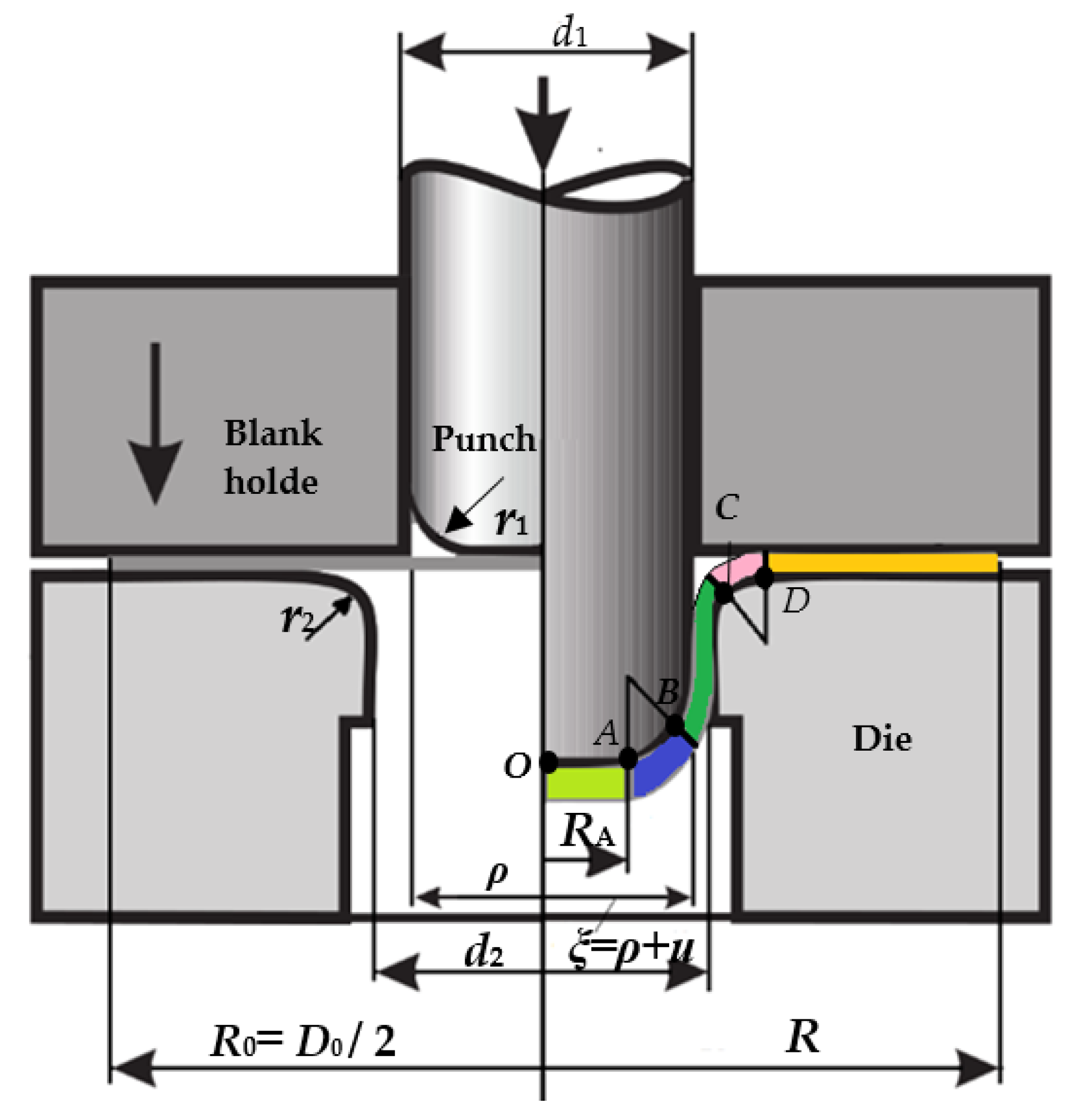
2.1. Theoretical Analysis
2.2. Basic Equations
- (1)
- Geometric equationwhere, is the original coordinate of a point before deformation. When the drawing height is h; w is the instantaneous axial coordinate of the point and is the instantaneous radial coordinate.
- (2)
- Flow equationwhere is the thickness anisotropy coefficient; , and are the equivalent stress, equivalent strain, and equivalent strain rate, respectively.
- (3)
- Constitutive equationwhere A is material coefficient; n is the hardening index.
- (4)
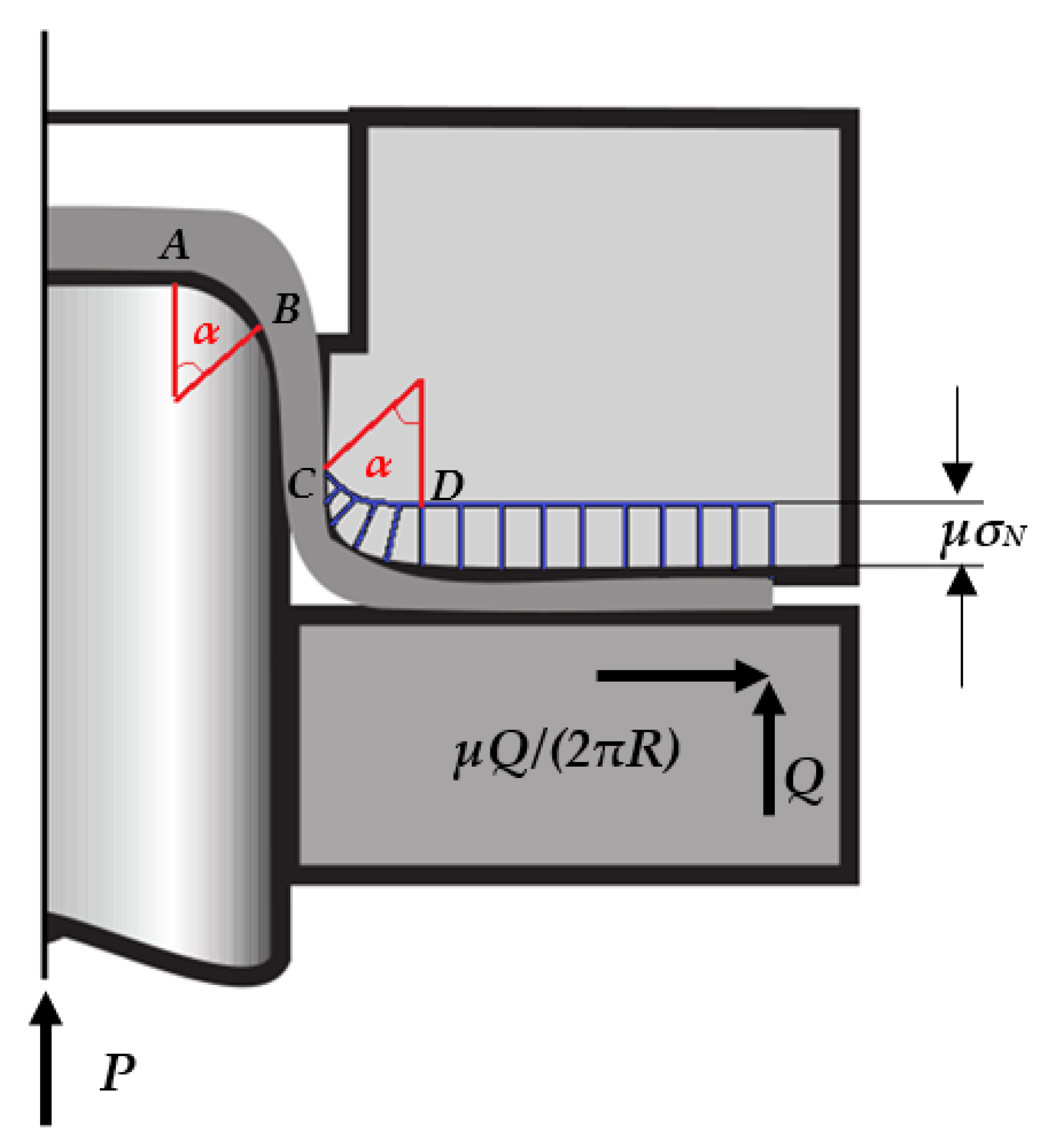
- Energy equationwhere is the join force on point i; is the displacement in force direction. The left side of the equation is the work done by the external load per unit time and the work consumed by the friction force of the contact surface in zone 4 and zone 5 per unit time. The right side of the equation is the plastic deformation work per unit time in zones 3, 4, and 5 and bending deformation work per unit time.
- (5)
- Equivalent strainThe equivalent strain is calculated by assuming that the area is unchanged and the geometric equation of symmetrical parts is:
- (6)
- Flow velocityThe radial displacement velocity of particles in each deformation area is:In the drawing process of symmetrical parts, the absolute flow velocity of particles on each friction surface is: in zone 4, in zone 5, the equivalent strain rate of particles in different deformation zones is deduced as:
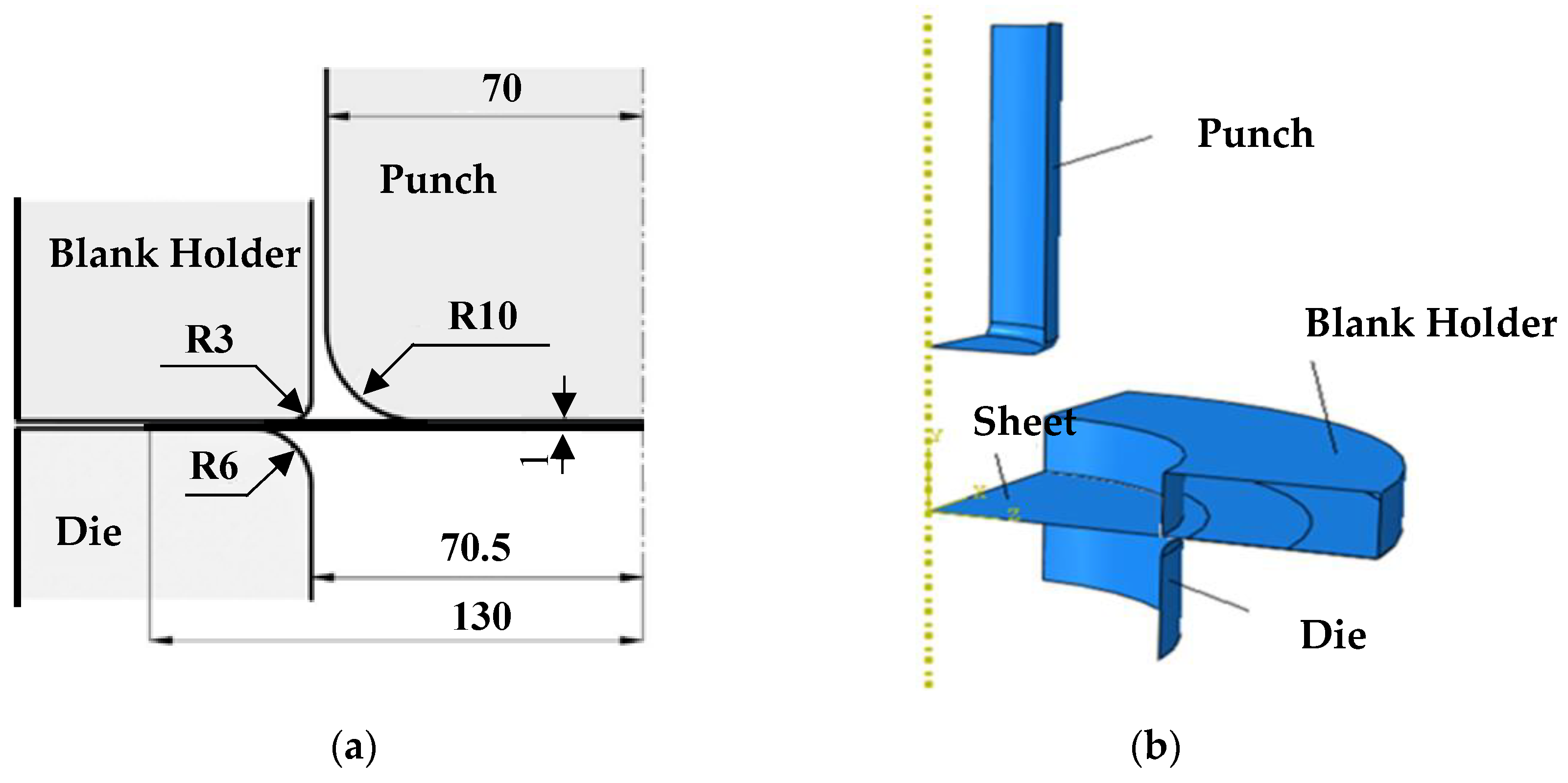
2.3. Axisymmetric Drawing Analysis
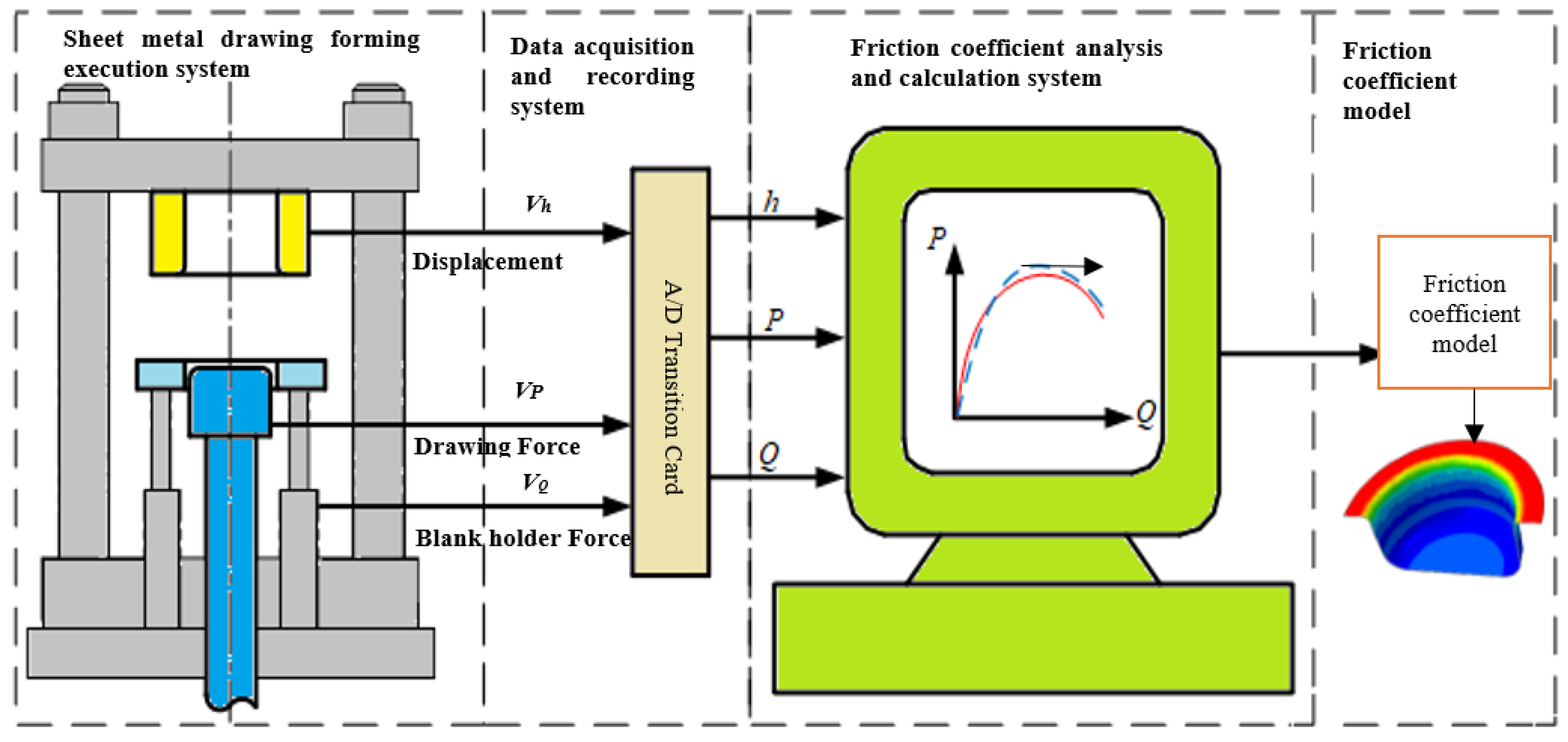
2.4. Algorithm for Friction Coefficient Calculation
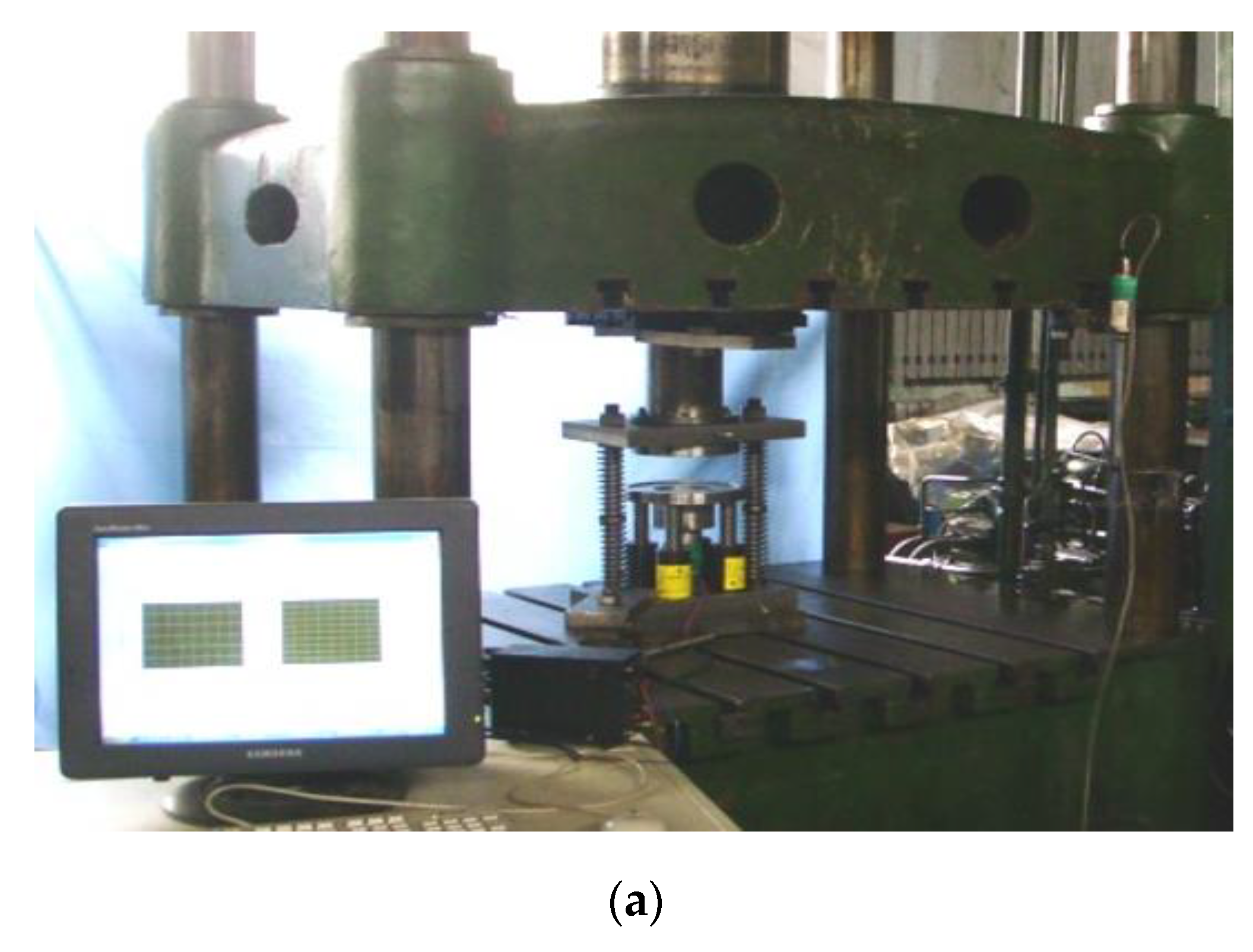
3. Materials and Experiment
3.1. Materials
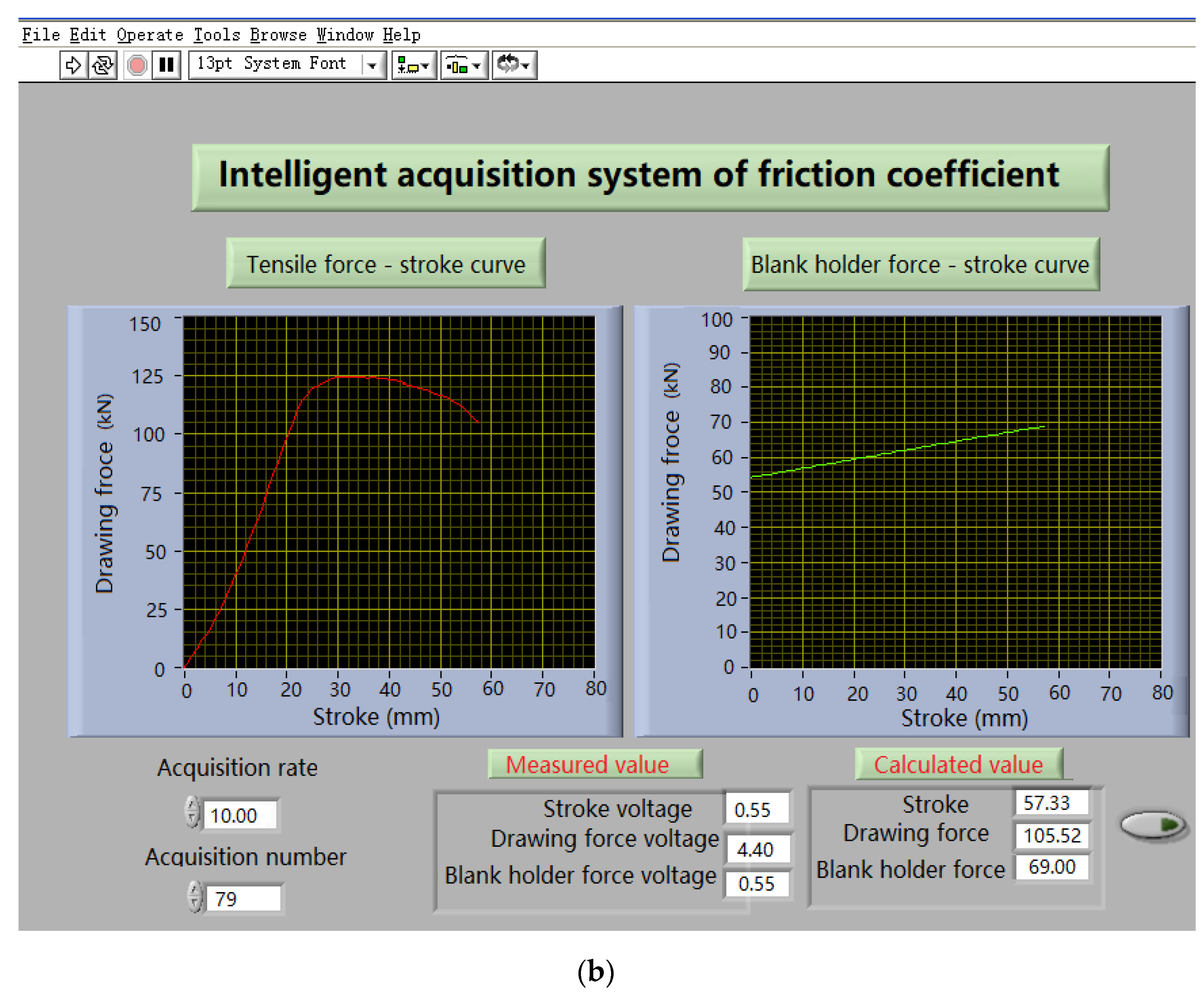
3.2. Friction Coefficient Measurement
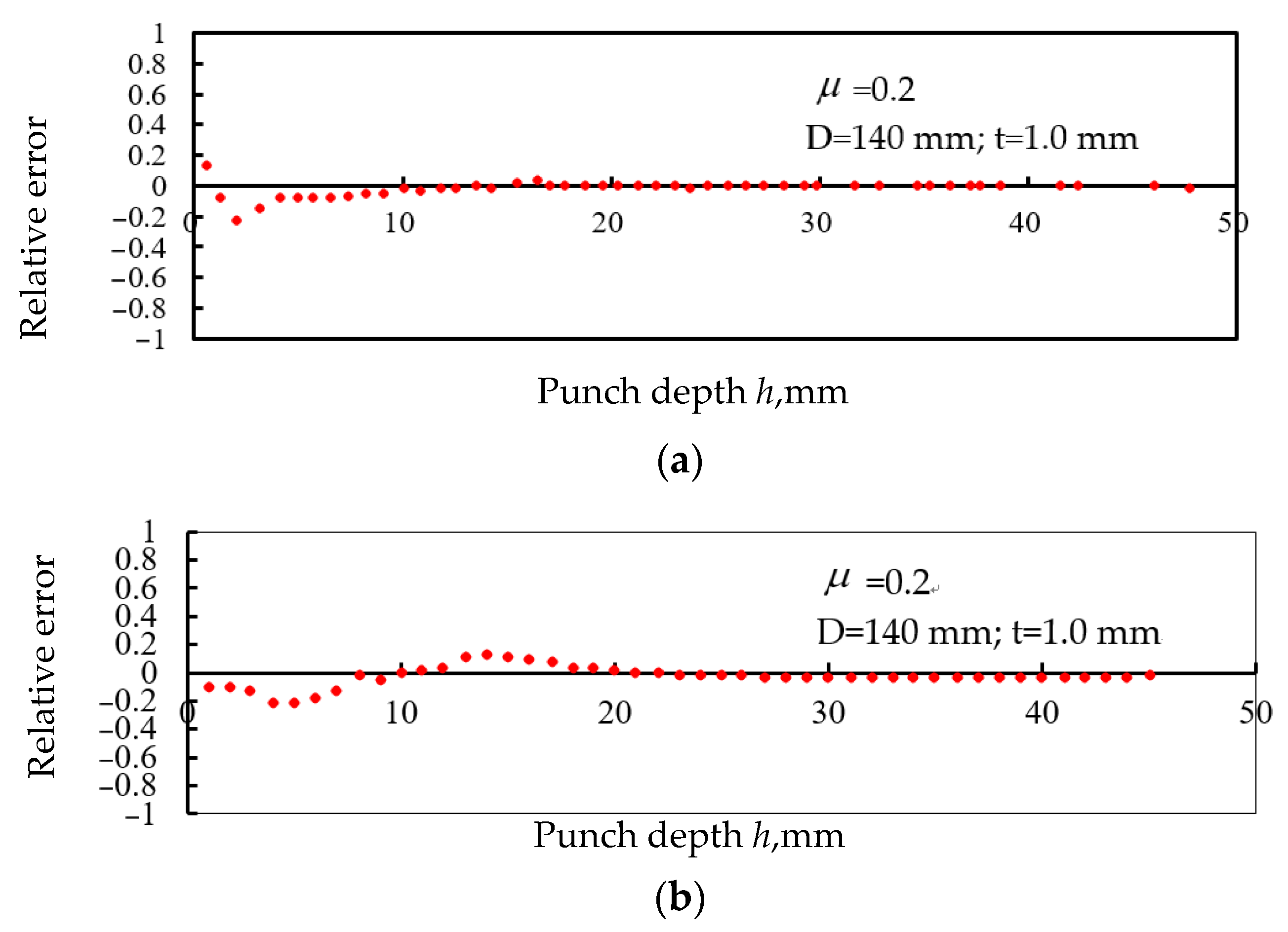
3.3. Error Analysis
4. Results and Discussion
- (1)
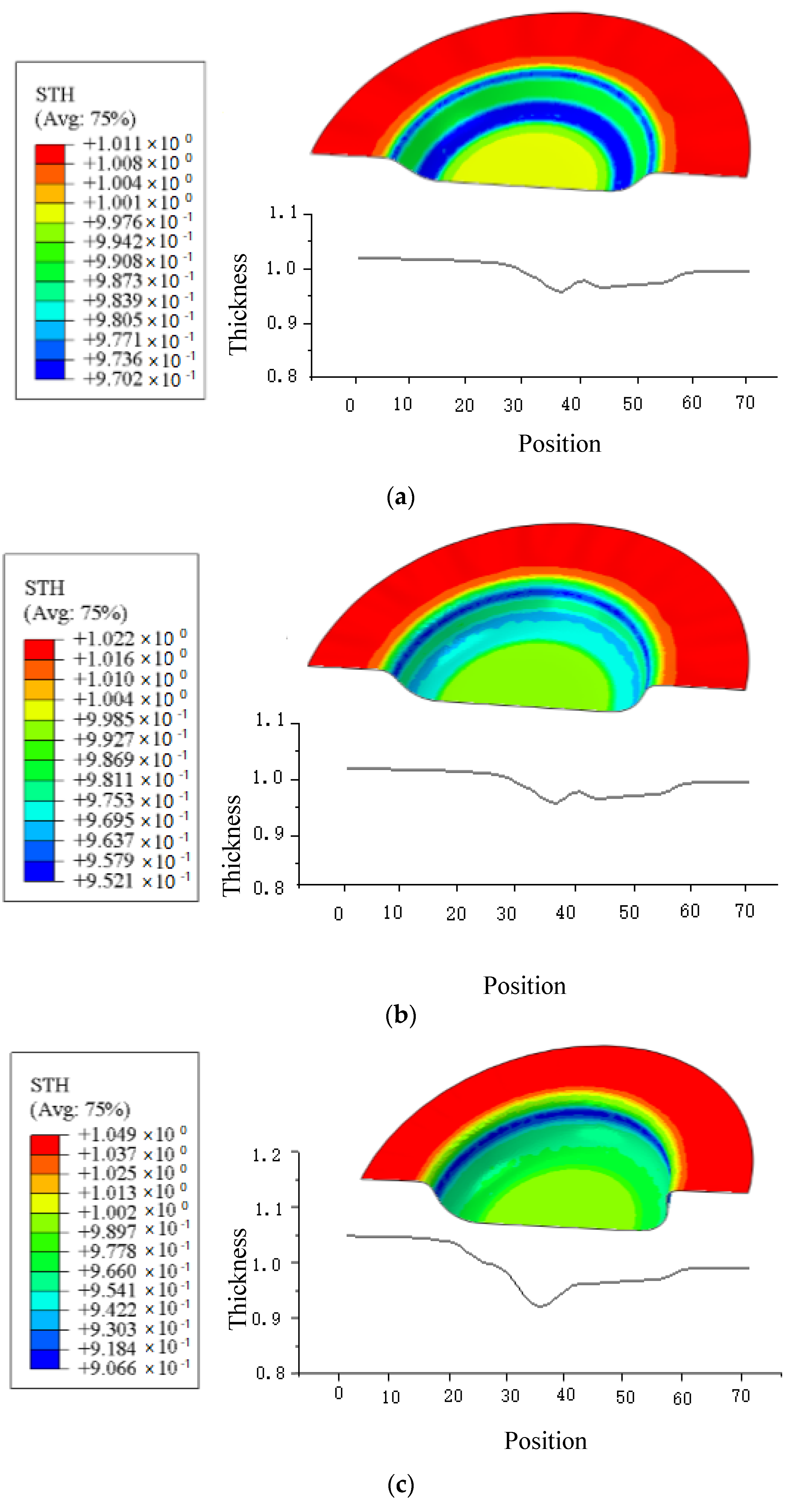
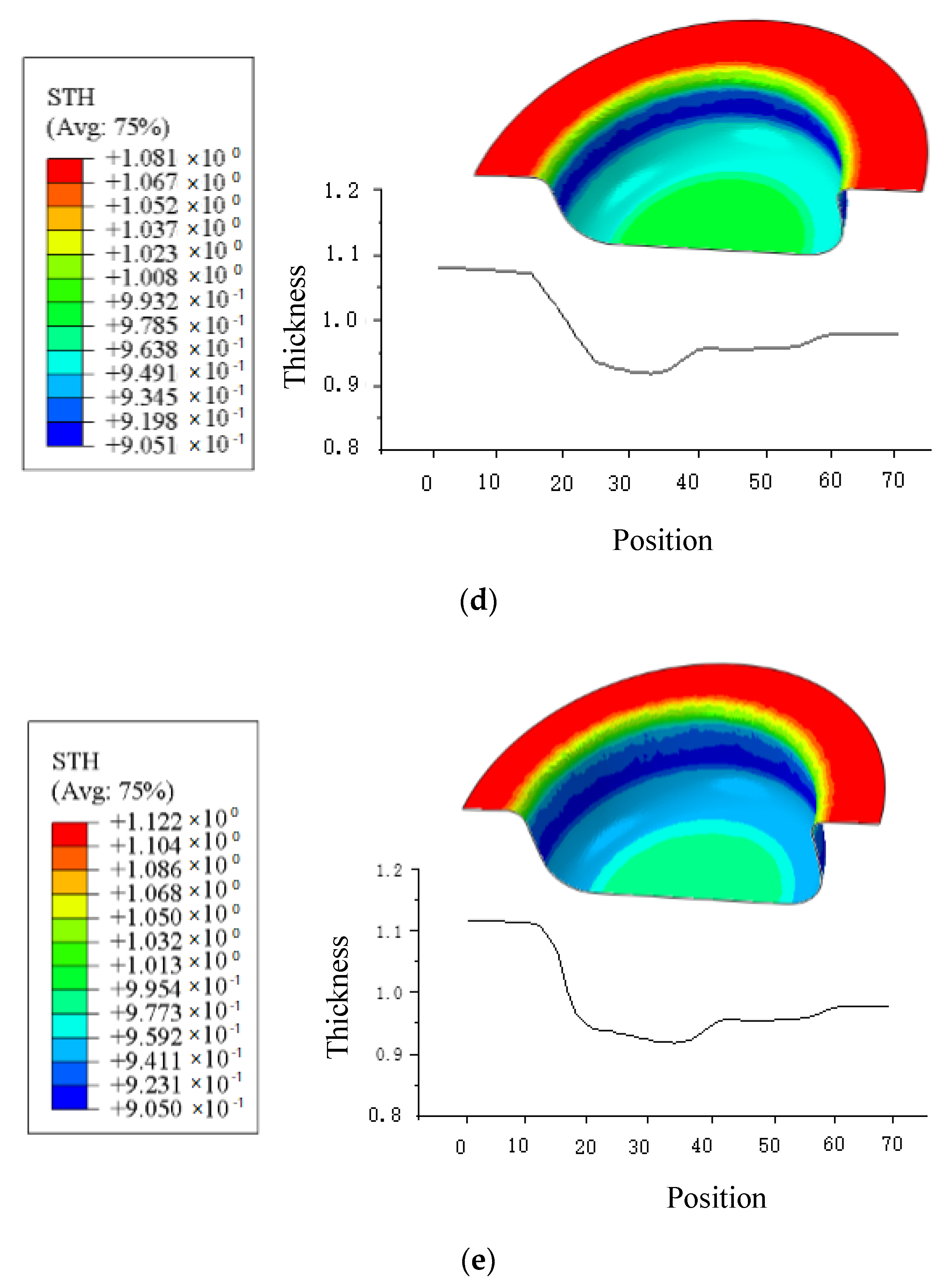
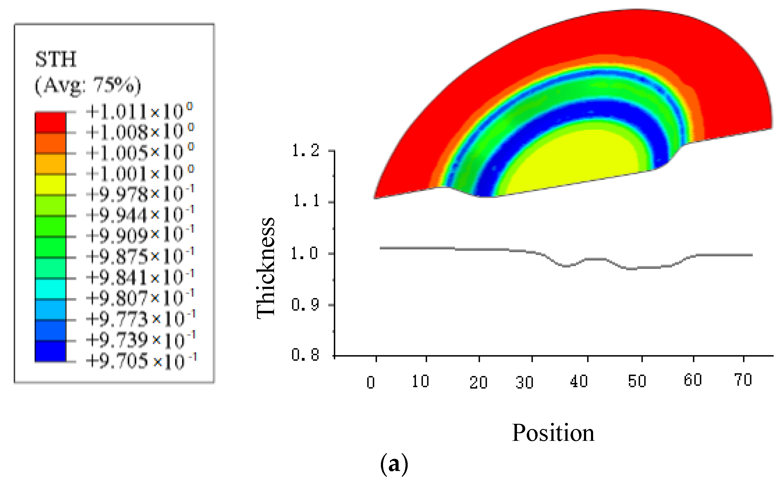
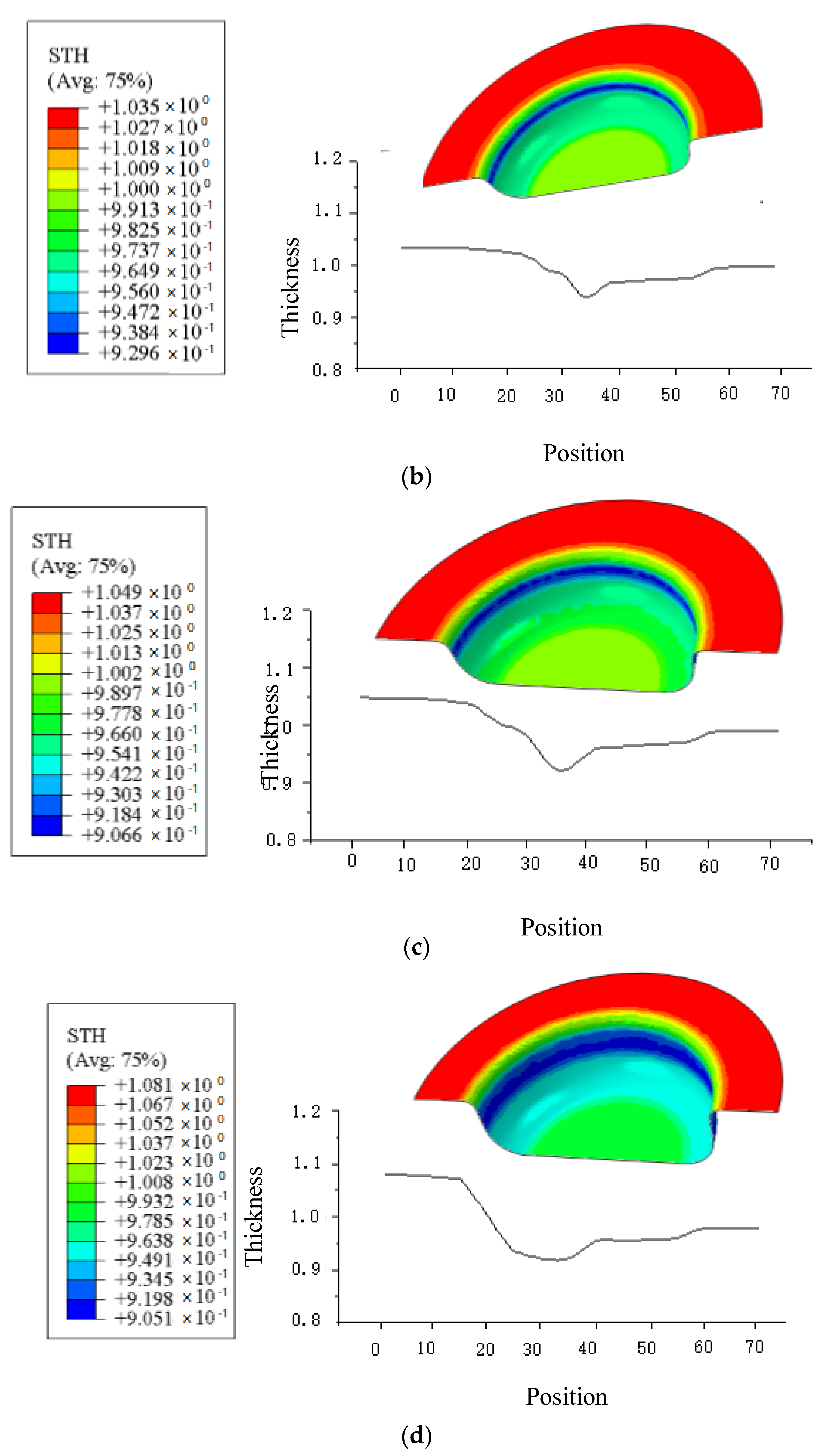
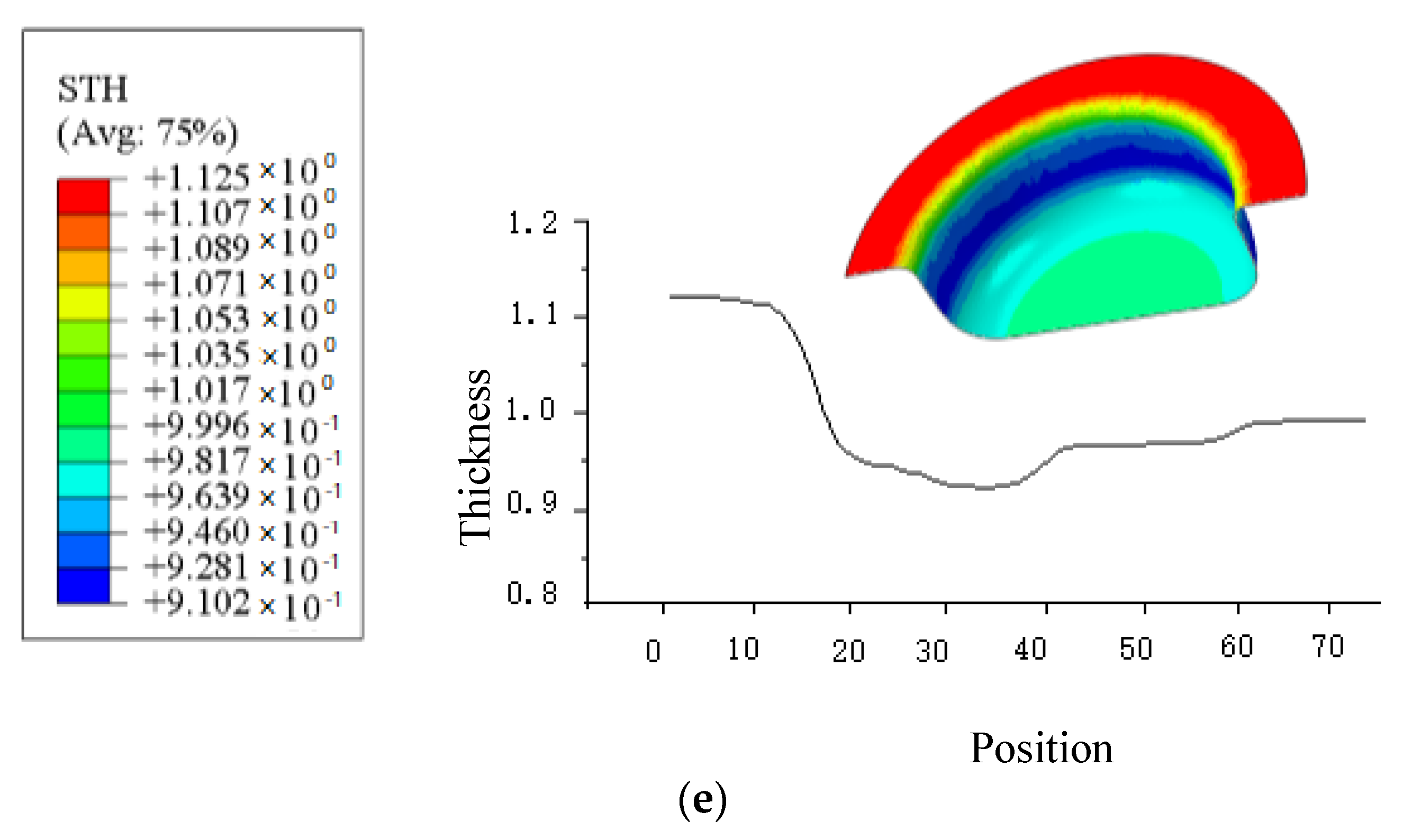
- The diameter of the flange area (zone 1) becomes smaller when deformed, resulting in the extrusion of the material and the thickness increase. The maximum thickness is 1.114 mm.
- (2)
- The material is continuously pulled into the die in the die’s fillet area (zone 2) and becomes a part of the straight wall. The material is plastically deformed and the wall thickness is thinned.
- (3)
- This area of the cylinder wall (zone 3) plays a role in transmitting the drawing force to the drawing material, with a small amount of radial elongation, resulting in the phenomenon of thickness thinning.
- (4)
- The punch fillet area (zone 4) is the transition area of the cylinder wall. The material is subjected to the dual action of the fillet surface’s compressive stress and tensile stress. The thinnest part of the whole part has low strength and a minimum of 0.831 mm.
- (5)
- At the beginning, the area at the bottom (zone 5) is pulled into the die and maintains a plane state. The friction at the fillet of the punch limits the outflow of materials. It is only subject to the compressive stress of the punch, with small deformation and slightly reduced thickness.
5. Conclusions
- (1)
- A theoretical model using Coulomb friction coefficient measurement in metal sheet forming is established, and the solution algorithm of friction coefficient in deep drawing of symmetrical cylindrical parts provides a theoretical basis for the research of friction coefficient measurement methods.
- (2)
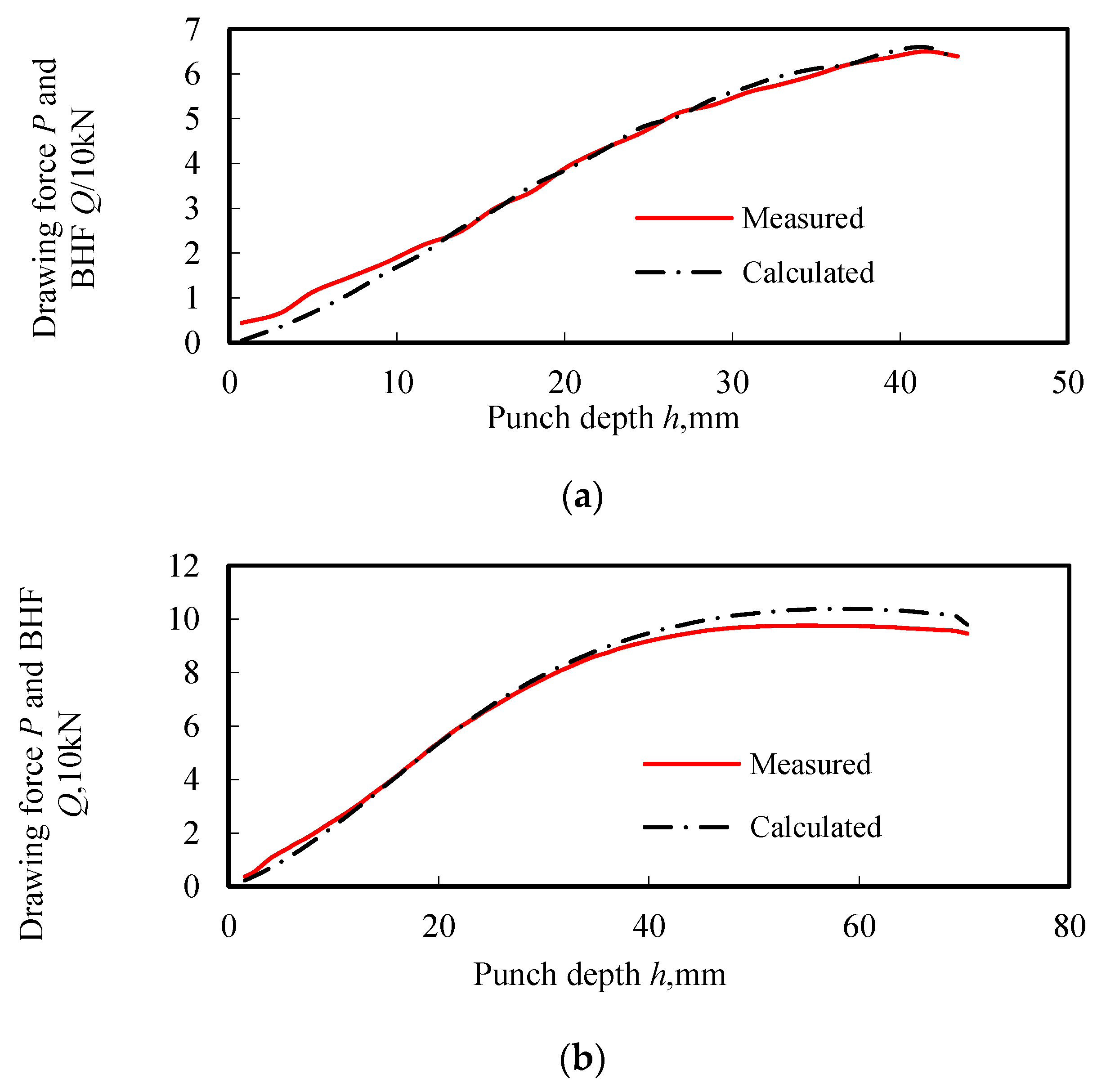
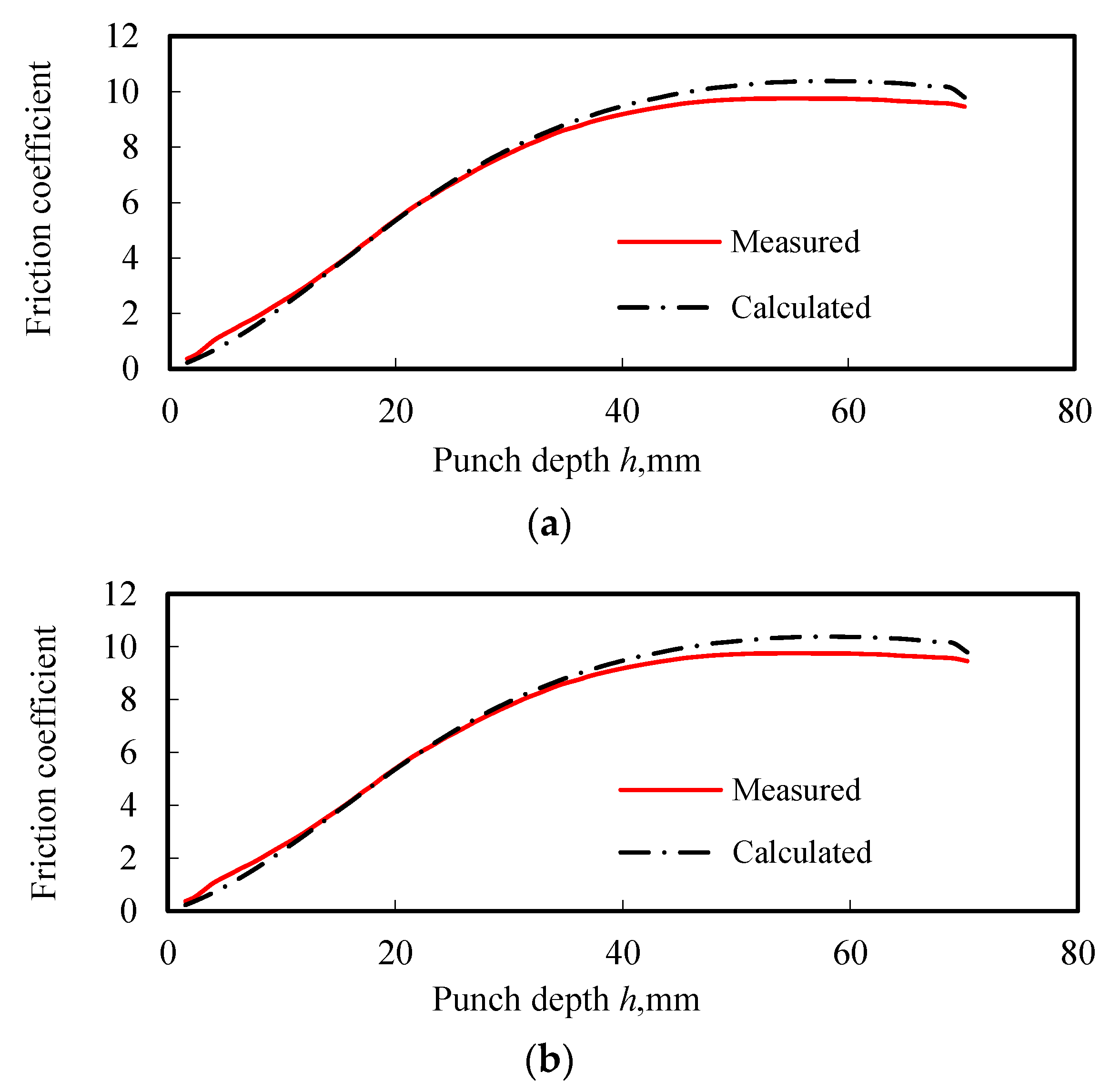
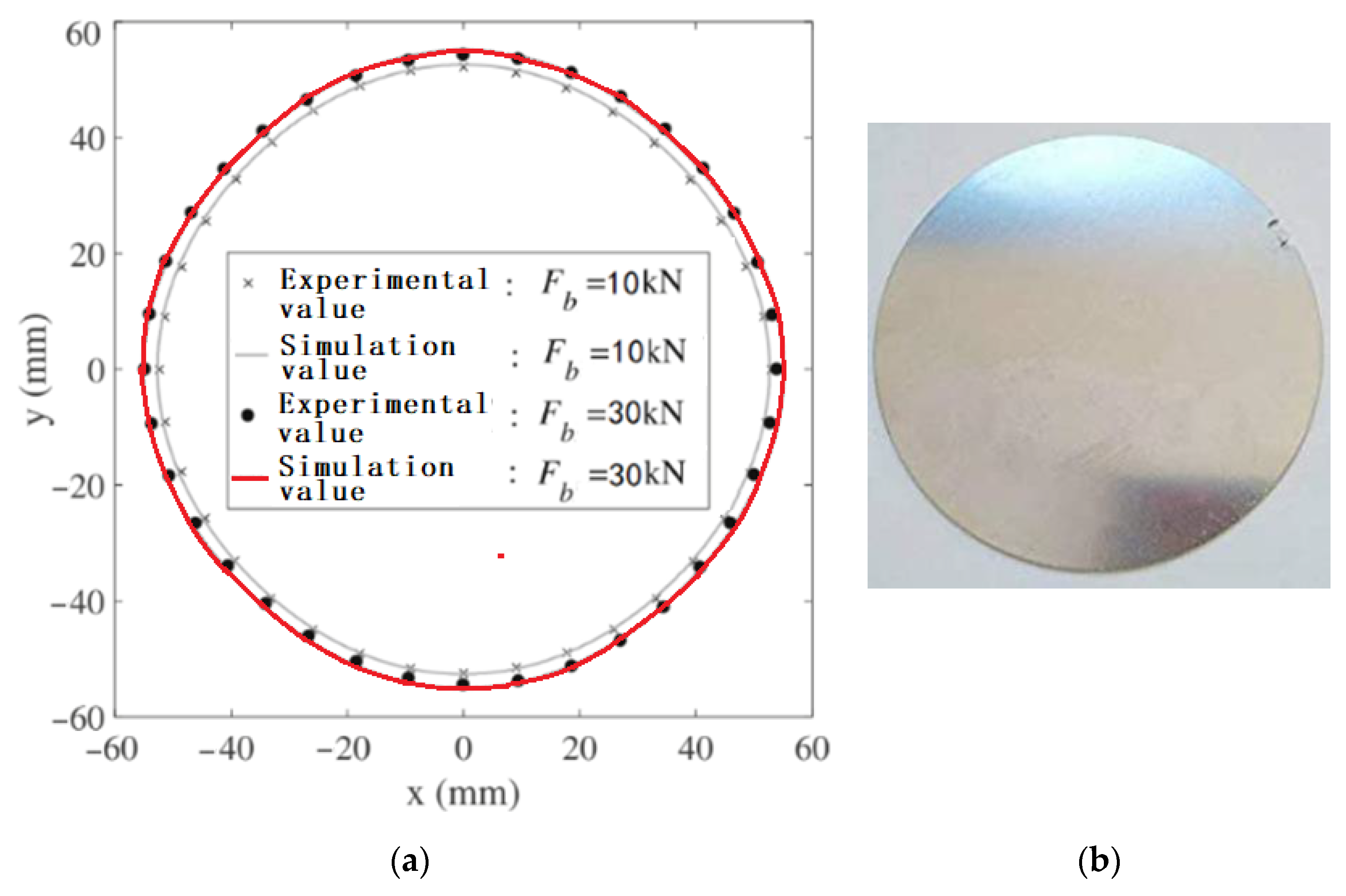
- The friction coefficients for two types of plates under different lubrication conditions are calculated using MATLAB software and measured experimentally, which shows a good agreement. This method can be used as a standard measurement method of friction in the sheet metal stamping process.
- (3)
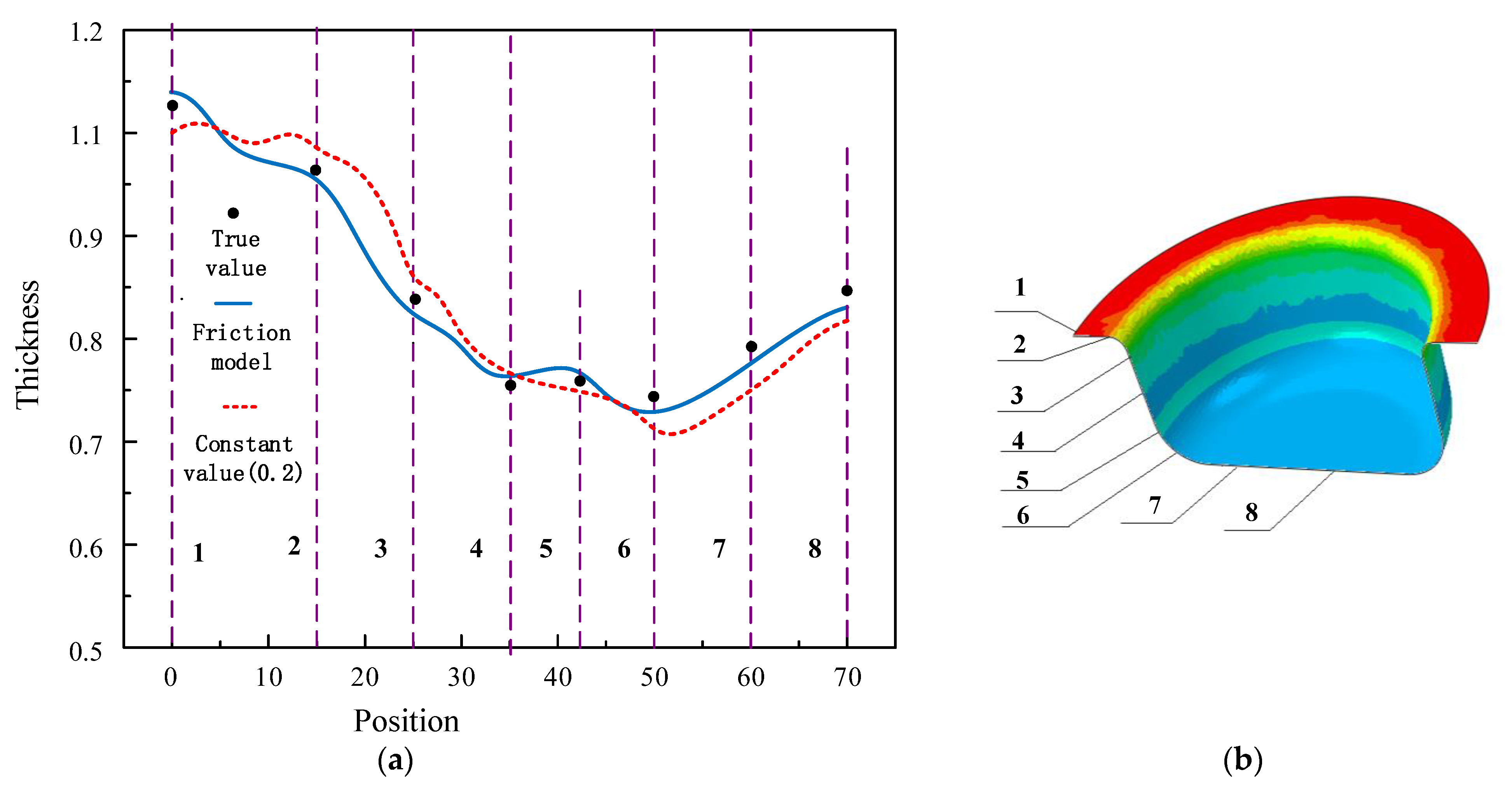
- With the comparison of fixed friction coefficients in finite element simulation for the drawing process of symmetrical parts, the new friction coefficient models can improve the simulation accuracy.
- (4)
- The application of the friction model can effectively improve the simulation accuracy of finite element software.
Author Contributions
Funding
Institutional Review Board Statement
Informed Consent Statement
Data Availability Statement
Conflicts of Interest
References
- Dou, S.; Wang, X.; Xia, J.; Wilson, L. Analysis of Sheet Metal Forming (Warm Stamping Process): A Study of the Variable Friction Coefficient on 6111 Aluminum Alloy. Metals 2020, 10, 1189. [Google Scholar] [CrossRef]
- You, K.; Kim, H.-K. A Study on the Effect of Process and Material Variables on the Hot Stamping Formability of Automotive Body Parts. Metals 2021, 11, 1029. [Google Scholar] [CrossRef]
- Evin, E.; Daneshjo, N.; Mareš, A.; Tomáš, M.; Petrovčiková, K. Experimental Assessment of Friction Coefficient in Deep Drawing and Its Verification by Numerical Simulation. Appl. Sci. 2021, 11, 2756. [Google Scholar] [CrossRef]
- Azushima, A.; Kudo, H. Direct Observation of Contact Behaviour to Interpret the Pressure Dependence of the Coefficient of Friction in Sheet Metal Forming. CIRP Ann. 1995, 209–212. [Google Scholar] [CrossRef]
- Dohda, K.; Wang, Z. Effects of Average Lubricant Velocity and Sliding Velocity on Friction Behavior in Mild Steel Sheet Forming. J. Tribol. 1998, 120, 724–728. [Google Scholar] [CrossRef]
- Ma, N.; Sugitomo, N. Development and Application of Non-linear Friction Models for Metal Forming Simulation. Conf. Proc. 2011, 1383, 382–389. [Google Scholar] [CrossRef]
- Wilson, W.R.D.; Hsu, T.C.; Huang, X.B. A Realistic Friction Model for Computer Simulation of Sheet Metal Forming Processes. J. Eng. Ind. 1995, 117, 202–209. [Google Scholar] [CrossRef]
- Comstock, R.J., Jr.; Kaiping, L.; Wagoner, R.H. Simulation of axisymmetric sheet forming tests. J. Mater. Processing Technol 2001, 117, 153–168. [Google Scholar] [CrossRef]
- Hildenbrand, A.; Bretault, N.; Hashimoto, K. Non-Linear Friction Laws Friction Coefficient as a Function of Contact Parameters. SAE Tech. Pap. Ser. 2006, 4, 39–45. [Google Scholar] [CrossRef]
- Hashimoto, K.; Isogai, E.; Yoshida, T.; Kuriyama, Y.; Ito, K. Finite element analysis of sheet metal forming taking account of nonlinear friction model-assessment of sheet formability by nonlinear friction model III. J. JSTP. 2008, 49, 995–999. [Google Scholar] [CrossRef] [Green Version]
- Dohda, K.; Boher, C.; Rezai-Aria, F.; Mahayotsanun, N. Tribology in metal forming at elevated temperatures. Friction 2015, 3, 1–27. [Google Scholar] [CrossRef] [Green Version]
- Bhushan, B.; Kulkarni, A.V. Effect of Normal Load on Microscale Friction Measurements. Thin Solid Films 1996, 2678, 293–333. [Google Scholar] [CrossRef]
- Chowdhury, M.A.; Khalil, M.K.; Nuruzzaman, D.M.; Rahaman, M.L. The Effect of Sliding Speed and Normal Load on Friction and Wear Property of Aluminum. J. Mec. Mechat. Eng. 2012, 11, 1–11. [Google Scholar]
- Ramezani, M.; Ripin, Z.M. Analysis of deep drawing of sheet metal using the Marform process. Int. J. Adv. Manuf. Technol. 2012, 59, 491–505. [Google Scholar] [CrossRef]
- Hol, J.; Alfaro, M.V.C.; Rooij, M.B.D.; Meinders, T. Advanced friction modeling for sheet metal forming. Key Eng. Mater. 2012, 286, 66–78. [Google Scholar] [CrossRef] [Green Version]
- Koyama, H.; Manabe, K.-I. Virtual processing in intelligent BHF control deep drawing. J. Mater. Process. Technol. 2003, 143–144, 261–265. [Google Scholar] [CrossRef]
- Wang, C.; Ma, R.; Zhao, J. Calculation method and experimental study of coulomb friction coefficient in sheet metal forming. J. Manuf. Process. 2017, 27, 126–137. [Google Scholar] [CrossRef]


| Components | Si | Fe | Cu | Mn | Mg | Cr | Zn | Ti | Al |
|---|---|---|---|---|---|---|---|---|---|
| % | 0.40 | 0.40 | 0.10 | 0.5 | 2.6~3.6 | 0.30 | 0.20 | 0.15 | Bal. |
| Components | C | Si | Mn | P | S | Ni | Cr | Cu |
|---|---|---|---|---|---|---|---|---|
| % | ≤0.12 | - | ≤0.12 | ≤0.04 | ≤0.045 | - | - | - |
| Sheet No. | Sampling Direction | Yield Strength | Tensile Strength | Uniform Elongation | Strength Coefficient B (MPa) | Hardening Exponent n | Thickness Anisotropy Coefficient r |
|---|---|---|---|---|---|---|---|
| SPCC | 0° | 205.187 | 277.652 | 24.742 | 484.93 | 0.223 | 2.387 |
| 45° | 216.582 | 291.925 | 25.468 | 507.56 | 0.220 | 1.498 | |
| 90° | 215.593 | 283.429 | 26.810 | 499.45 | 0.229 | 2.143 | |
| Ave. | 212.454 | 284.335 | 25.673 | 497.31 | 0.224 | 2.009 | |
| Al-5754 | 0° | 112.31 | 212.64 | 22.361 | 407.96 | 0.247 | 0.748 |
| 45° | 109.31 | 215.63 | 24.245 | 415.85 | 0.278 | 0.845 | |
| 90° | 108.94 | 213.37 | 24.157 | 424.61 | 0.273 | 0.794 | |
| Ave. | 110.187 | 213.88 | 23.588 | 416.14 | 0.266 | 0.796 |
| Positions | Actual Value (mm) | Friction Coefficient Model (mm) | |
|---|---|---|---|
| 1 | 1.108 | 1.078 (Error: −2.70%) | 1.085 (Error: −2.07%) |
| 2 | 1.071 | 1.045 (Error: −2.43%) | 1.060 (Error: −1.03%) |
| 3 | 0.925 | 0.903 (Error: −2.38%) | 0.938 (Error: 1.41%) |
| 4 | 0.892 | 0.823 (Error: −7.74%) | 0.908 (Error: 1.79%) |
| 5 | 0.875 | 0.837 (Error: −4.34%) | 0.852 (Error: −2.63%) |
| 6 | 0.843 | 0.807 (Error: −2.47%) | 0.831 (Error: −1.42%) |
| 7 | 0.851 | 0.815 (Error: −4.23%) | 0.835 (Error: −1.88%) |
| 8 | 0.845 | 0.863 (Error: 2.138%) | 0.856 (Error: 1.30%) |
Publisher’s Note: MDPI stays neutral with regard to jurisdictional claims in published maps and institutional affiliations. |
© 2022 by the authors. Licensee MDPI, Basel, Switzerland. This article is an open access article distributed under the terms and conditions of the Creative Commons Attribution (CC BY) license (https://creativecommons.org/licenses/by/4.0/).
Share and Cite
Xia, J.; Zhao, J.; Dou, S.; Shen, X. A Novel Method for Friction Coefficient Calculation in Metal Sheet Forming of Axis-Symmetric Deep Drawing Parts. Symmetry 2022, 14, 414. https://doi.org/10.3390/sym14020414
Xia J, Zhao J, Dou S, Shen X. A Novel Method for Friction Coefficient Calculation in Metal Sheet Forming of Axis-Symmetric Deep Drawing Parts. Symmetry. 2022; 14(2):414. https://doi.org/10.3390/sym14020414
Chicago/Turabian StyleXia, Jiansheng, Jun Zhao, Shasha Dou, and Xing Shen. 2022. "A Novel Method for Friction Coefficient Calculation in Metal Sheet Forming of Axis-Symmetric Deep Drawing Parts" Symmetry 14, no. 2: 414. https://doi.org/10.3390/sym14020414