
A Method to Design Profiled Cutting Tools for Inner Turning


Abstract
:1. Introduction
1.1. Literature Review on Profiled Cutting Tools
1.2. Conclusion on the Literature Review
- The range of subjects approached is wide, including the geometry of the profiled cutting tools, different cutting processes (turning, milling, and grinding), the precision of the profiled surfaces engendered, the micro profile of the surface, that is the roughness, and other factors;
- The researchers approached cutting tools for profiled surfaces placed both on cylindrical and helical surfaces;
- Designing the profile of cutting tools has rarely been approached;
- Inner turning of the profiled surfaces was not considered.
2. Materials and Method
2.1. Method
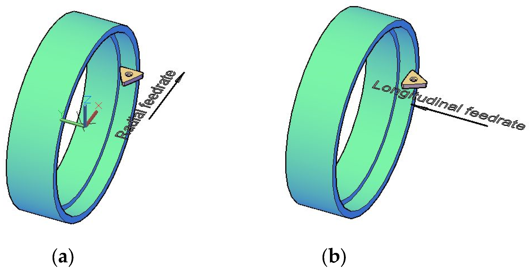
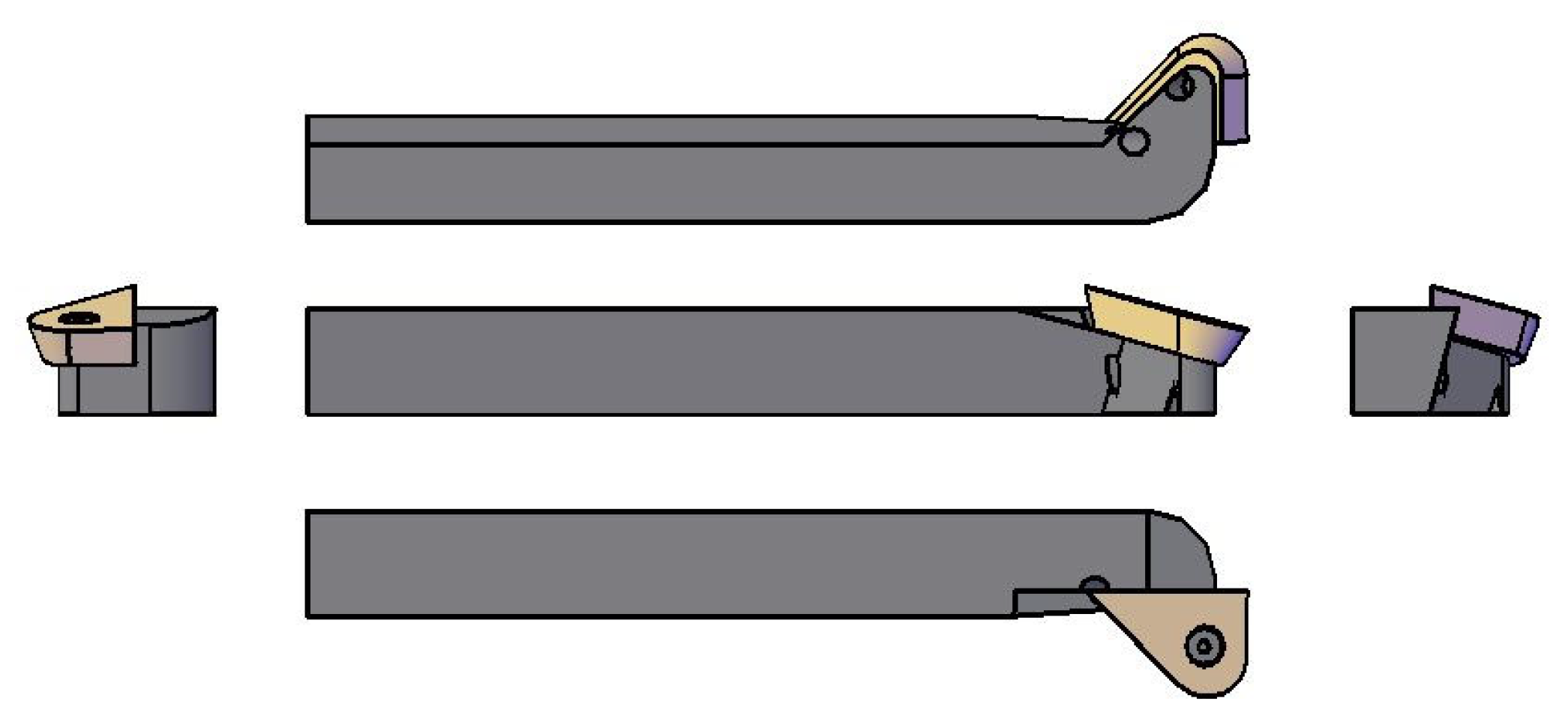
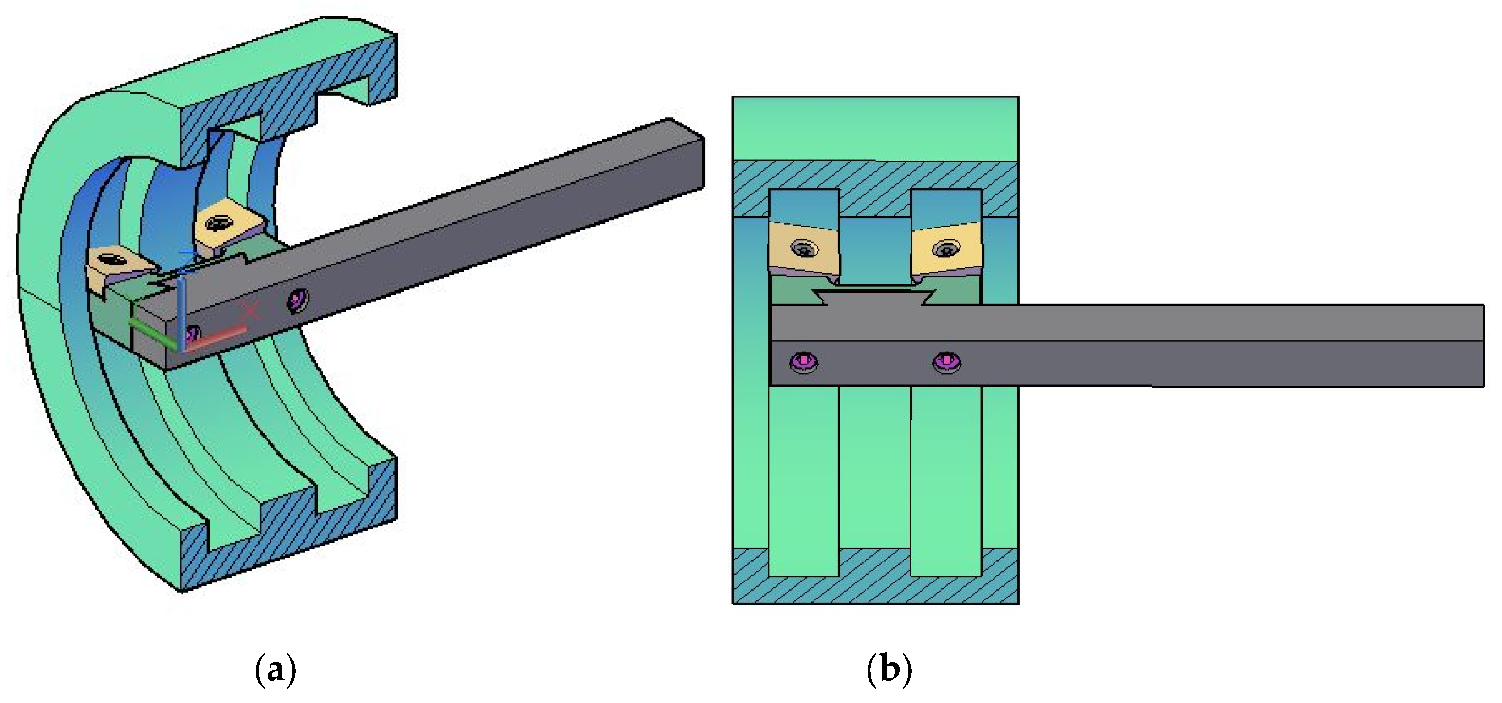
- The angle at the cutting insert is tilted against the direction of the workpiece’s axis;
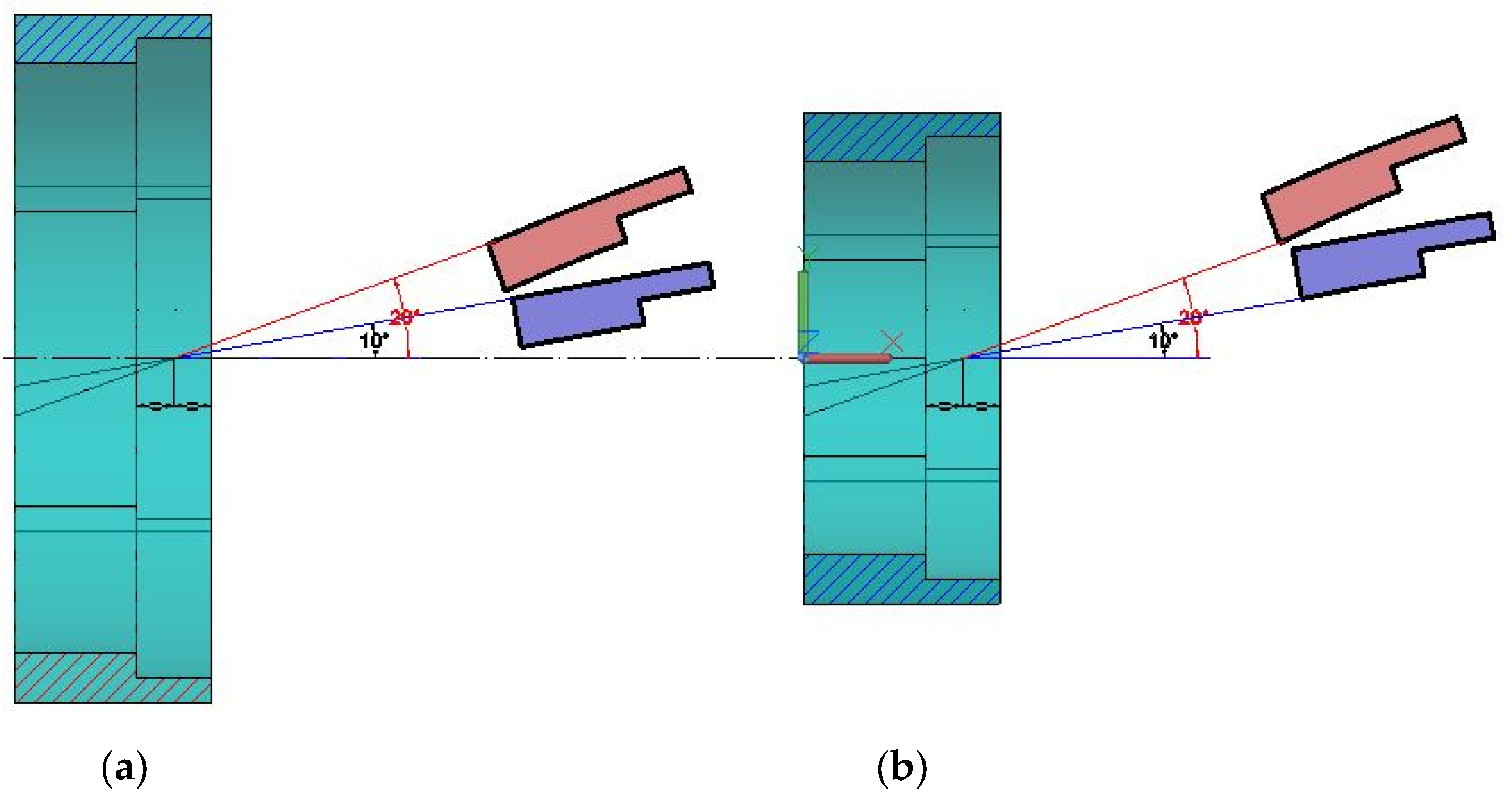
- Due to the curvature of the part, special attention has to be paid to the clearance angle of the cutting tool. It is noted above that this acts dissymmetrically on the two sides of the workpiece. Depending on the direction in which the cutting edge is tilted, the actual clearance angle increases at one side and decreases at the other one. Even for the side with the smaller effective clearance angle, this still has to be positive and at a reasonable value (at least 2.5°, depending on the material to be machined);
- The bigger the tilting angle of the cutting insert, the bigger the undercut;
- The inner radius of the workpiece directly influences the shape of the cutting insert.
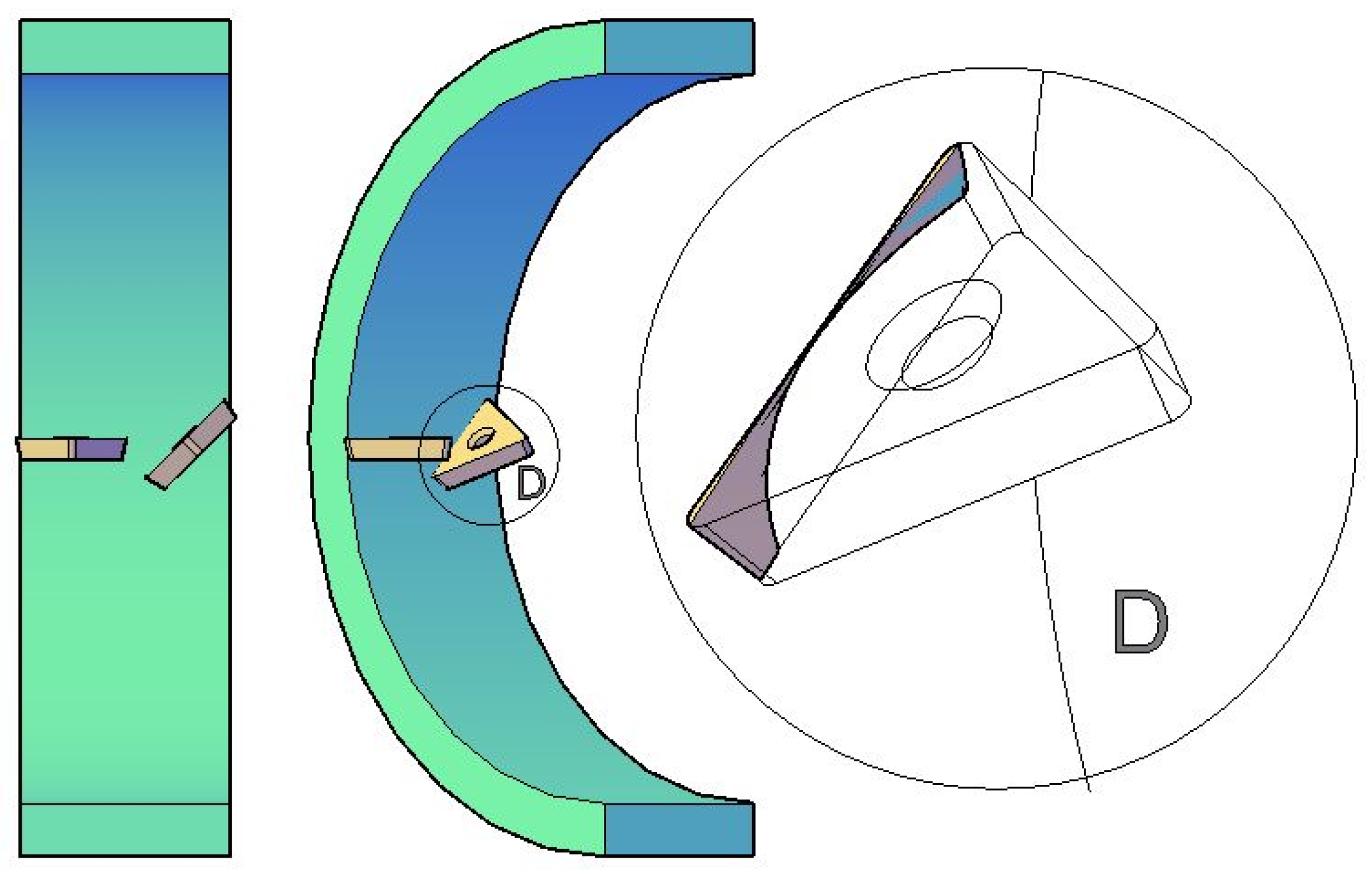
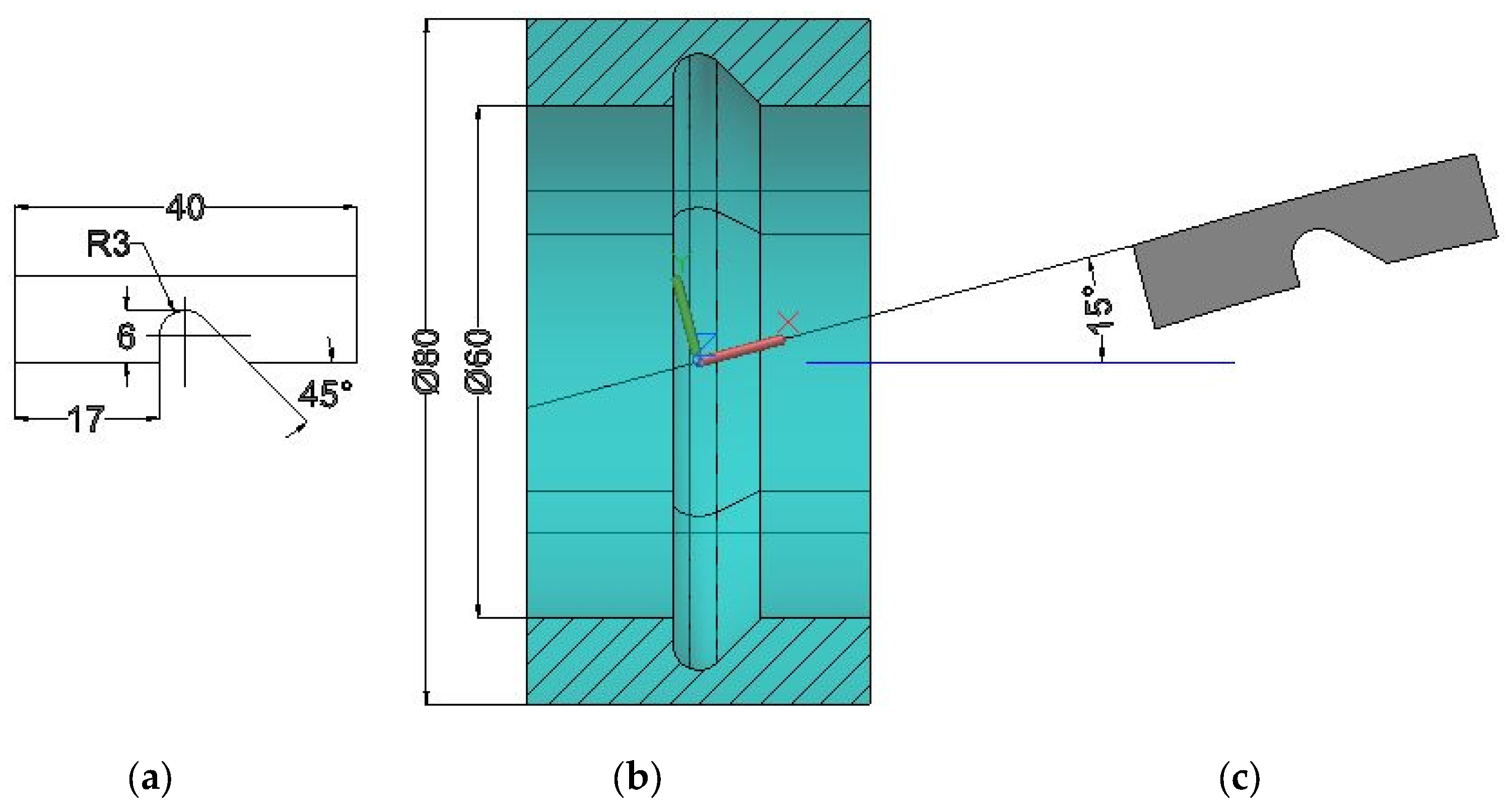
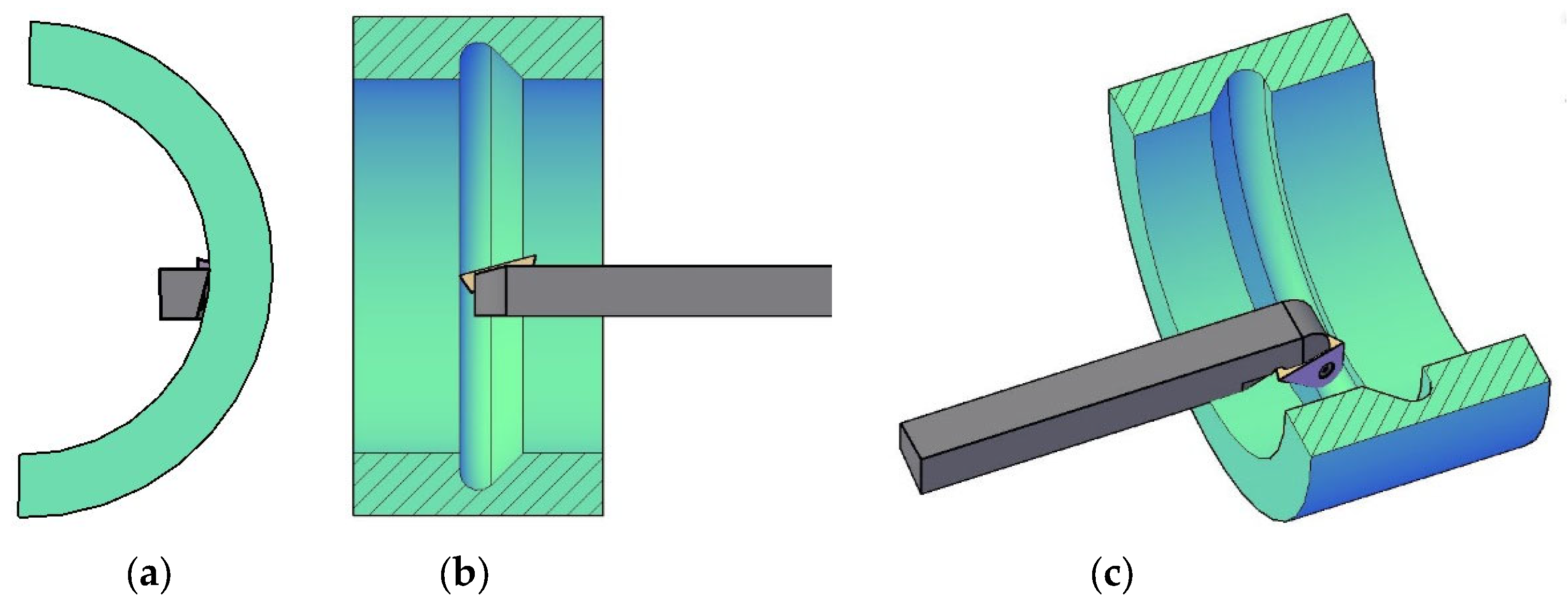
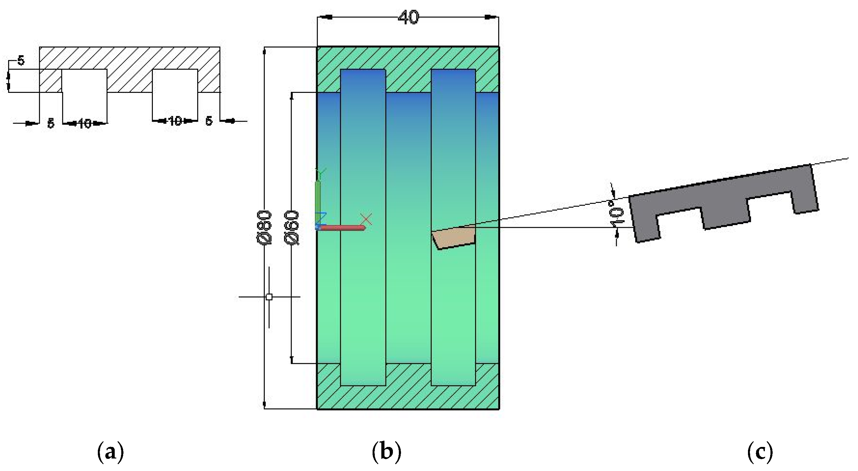
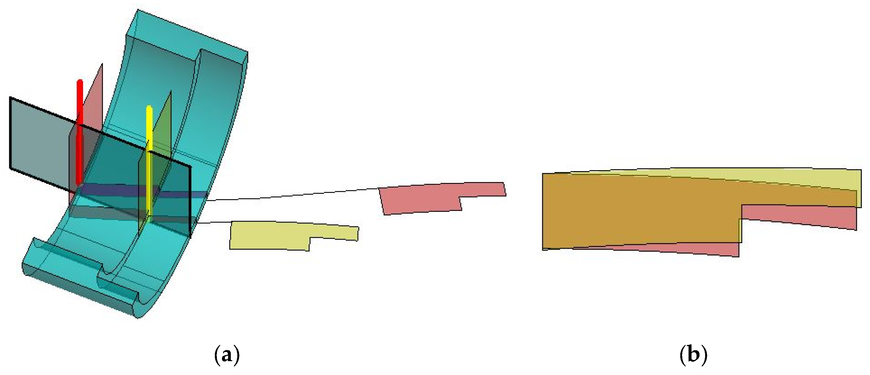
- Create a section through the workpiece with a plane that contains the intended cutting edge. If the profile is a symmetric one, it is recommended that the plane be rotated against the radius of the workpiece, at the level of the symmetric plane of the profile (Figure 4). In this way, during machining, half of the cutting edge is above the horizontal radial plane of the workpiece, and half is below it;
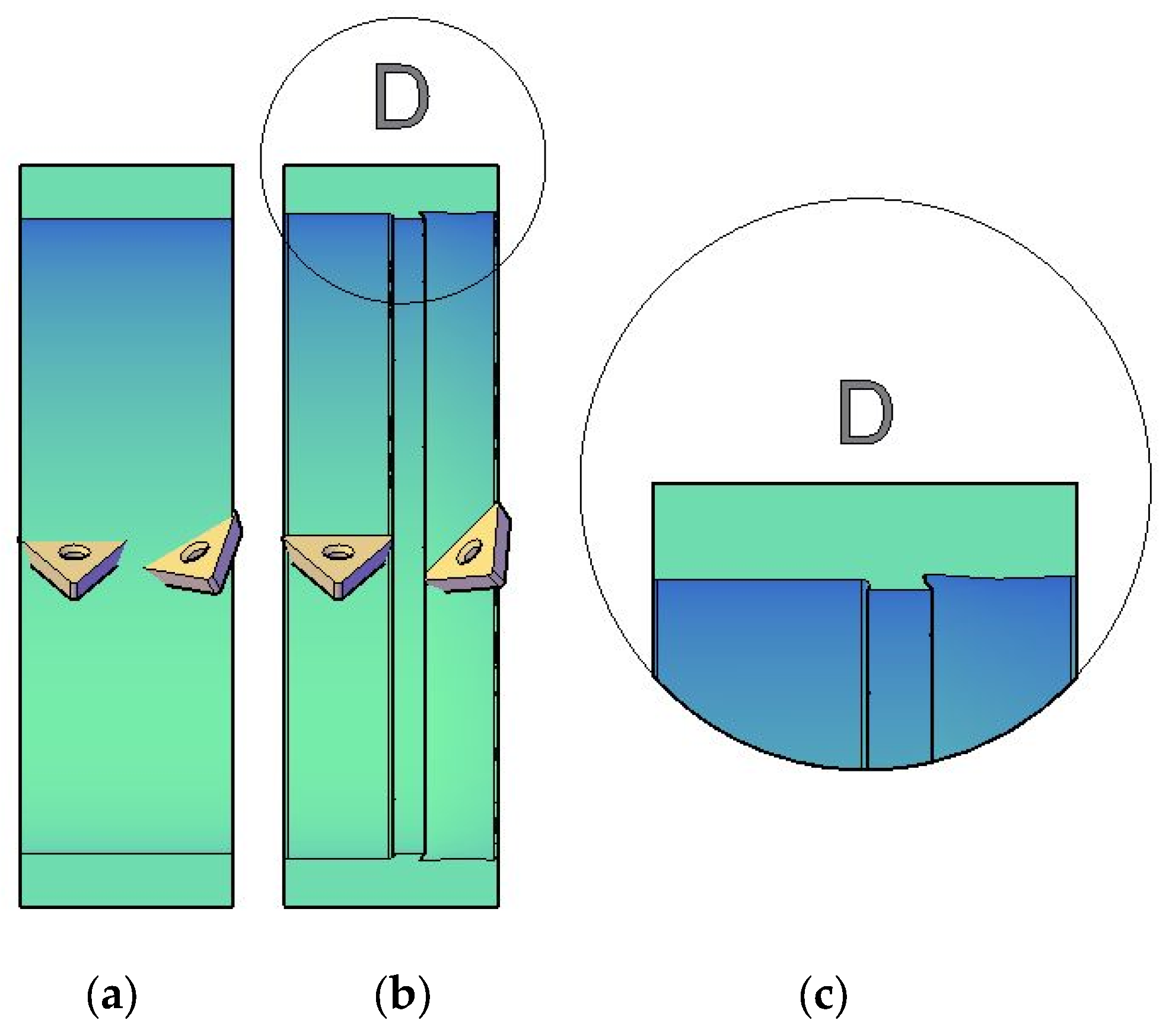
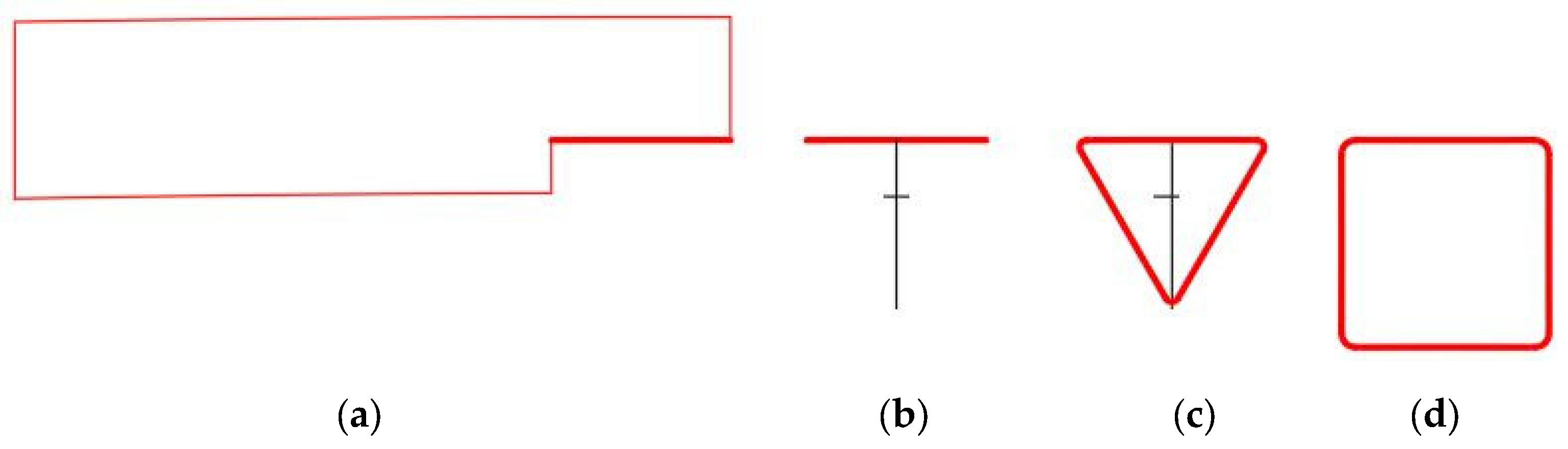
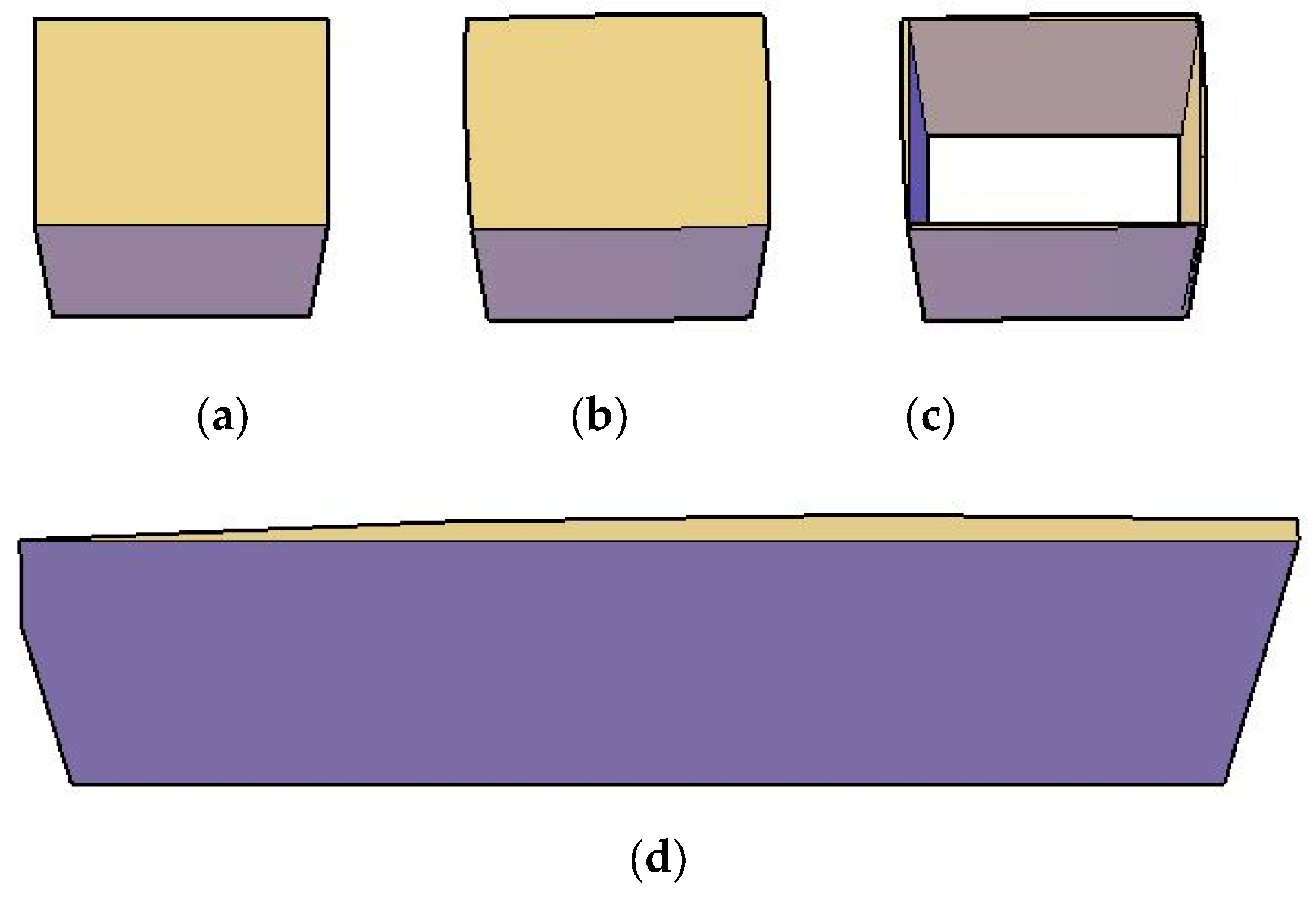
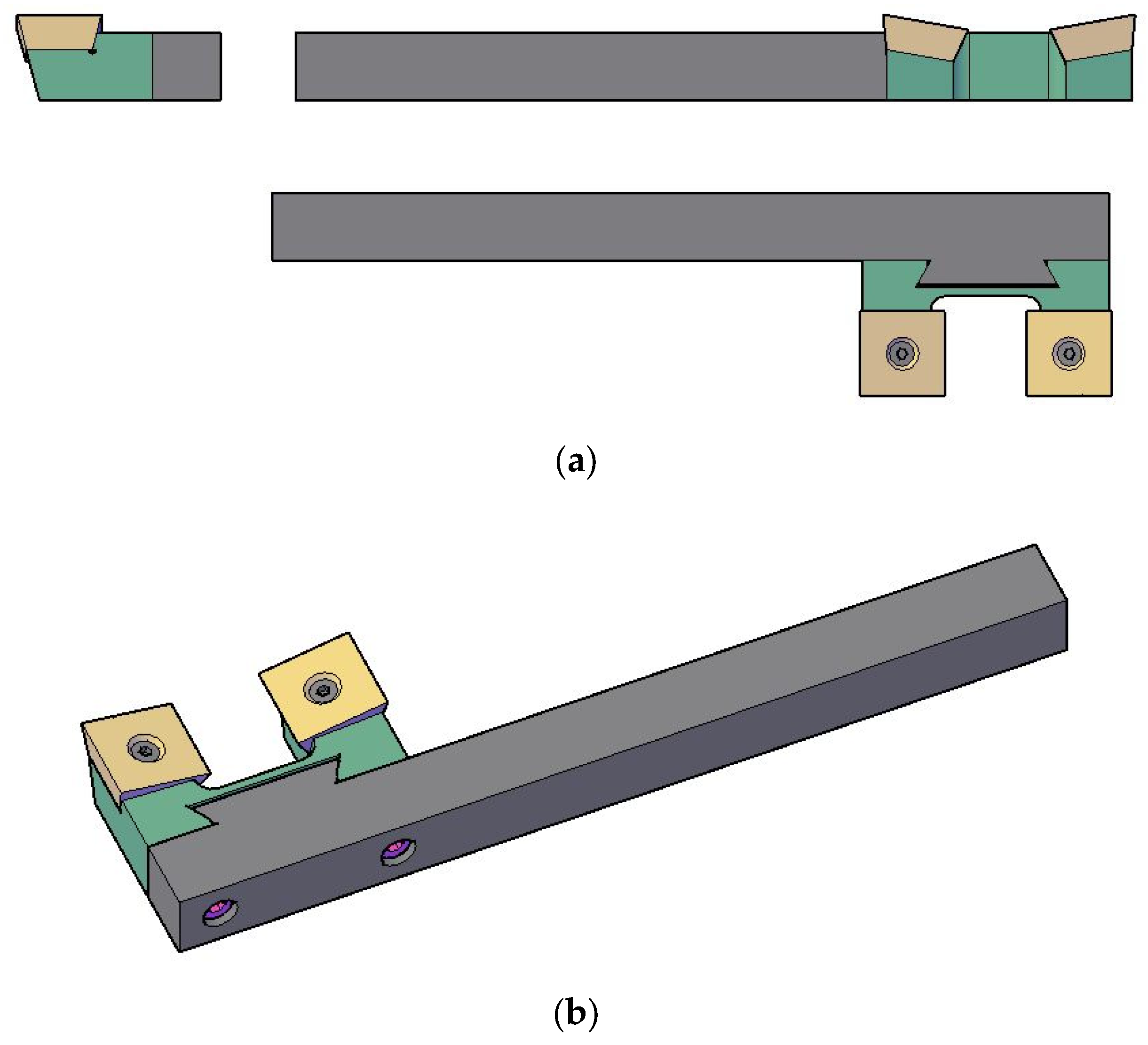
- Create the contour of the cutting insert with the desired number of edges and nose radius (Figure 5c,d);
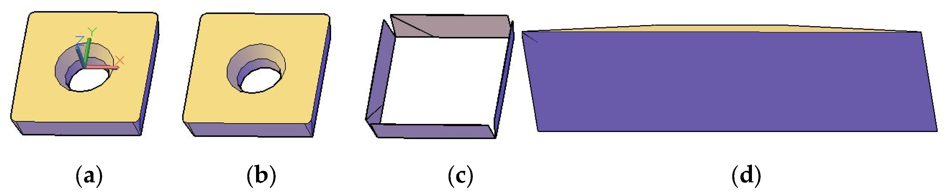
- Create a tapered extrusion of the contour to obtain the body of the cutting insert, and add a hole for clamping the cutting insert onto its support (Figure 6);
- If needed, some flanks of the cutting insert can also be tapered, to obtain even clearance angles on both sides of the insert.
2.2. Conclusion on the Method
3. Results
3.1. Case Study #1
3.2. Case Study #2
4. Discussion
5. Conclusions
Author Contributions
Funding
Conflicts of Interest
References
- Boryczko, A. Profile irregularities of turned surfaces as a result of machine tool interactions. Metrol. Meas. Syst. 2011, 18, 691–699. [Google Scholar] [CrossRef] [Green Version]
- Lu, C.; Ma, N.; Chen, Z.; Costes, J.P. Pre-evaluation on surface profile in turning process based on cutting parameters. Int. J. Adv. Manuf. Technol. 2010, 49, 447–458. [Google Scholar] [CrossRef] [Green Version]
- Liu, X.D.; Lee, L.C.; Ding, X.; Fang, F.Z. Ultraprecision turning of aspherical profiles with deep sag. In Proceedings of the IEEE International Conference on Industrial Technology, Bangkok, Thailand, 11–14 December 2002; pp. 1152–1157. [Google Scholar]
- Moroni, G.; Pacella, M.; Elia, A. On the simulation of roundness profiles obtained by turning. In Proceedings of the 4th International Industrial Simulation Conference, Palermo, Italy, 5–7 June 2006; p. 277. [Google Scholar]
- Sung, A.N.; Ratnam, M.M.; Loh, W.P. Effect of tool nose profile tolerance on surface roughness in precision turning. In Proceedings of the International Conference on Intelligent Robotics, Automation and manufacturing, Kuala Lumpur, Malaysia, 28–30 November 2012; pp. 475–482. [Google Scholar]
- Sharkov, O.V.; Koryagin, S.I.; Velikanov, N.L. Forming the profile of cutting tools for manufacture of fine-module ratchet teeth. In Proceedings of the International Conference on Modern Trends in Manufacturing Technologies and Equipment, Sevastopol, Russia, 7–11 September 2020; pp. 1437–1440. [Google Scholar]
- Sharkov, O.V.; Koryagin, S.I.; Velikanov, N.L. Determination of the rational profile of fine-module ratchet teeth when cutting with a rack-type tool. In Proceedings of the 13th International Conference on Mechanical Engineering, Automation and Control Systems, Novosibirsk, Russia, 12–14 December 2018. [Google Scholar]
- Belyaev, S.V.; Gordeev, V.F. Algorithms for calculating disk tool profiles for cutting helical surfaces. Sov. Eng. Res. 1982, 2, 98–99. [Google Scholar]
- Nieszporek, T.; Boral, P.; Golebski, R. Particular solution of cutting tool path applied on helical surface with circular profile. Teh. Vjesn. 2019, 26, 22–28. [Google Scholar]
- Sun, Y.W.; Wang, J.; Guo, D.M.; Zhang, Q. Modeling and numerical simulation for the machining of helical surface profiles on cutting tools. Int. J. Adv. Manuf. Technol. 2008, 36, 525–534. [Google Scholar] [CrossRef]
- Radzevich, S.P. Profiling of the form-cutting tools of optimal design. In Kinematic Geometry of Surface Machining; Radzevich, S.P., Ed.; CRC Press-Taylor & Francis Group: Boca Raton, FL, USA, 2011; pp. 153–216. [Google Scholar]
- Kulikov, M.Y.; Nakhushev, R.S.; Evseev, D.G.; Volkov, D.V. Method of calculation of the main cutting edge form for turn-milling profile. In Proceedings of the IEEE International Conference Quality Management, Transport and Information Security, Information Technologies, St Petersburg, Russia, 24–28 September 2018; pp. 117–120. [Google Scholar]
- Lechowski, T.; Baranowski, W. Effect of error in tool setting during turning on accuracy of worm profiles. Mech. Mies. Nauk.-Tech. 1977, 50, 5–7. [Google Scholar]
- Ishibashi, A.; Yoshino, H. Design and manufacture of gear cutting tools and gears with an arbitrary profile. JSME Int. J. 1987, 30, 1159–1166. [Google Scholar] [CrossRef] [Green Version]
- Yoshino, H.; Ishibashi, A. A method for calculating grinding wheel-profile for hob finishing—Design and manufacture of gear cutting tools and gears with an arbitrary profile. JSME Int. J. III-Vib. C 1989, 32, 124–130. [Google Scholar] [CrossRef]
- Mahmoud, I. Determining the working angle of profile tools for tangential cutting. WT-Z. Ind. Fertigung. 1982, 72, 31–32. [Google Scholar]
- Sambhav, K.; Tandon, P.; Dhande, S.G. Geometric modeling and analysis of single point cutting tools with generic profile. In Proceedings of the ASME International Manufacturing Science and Engineering Conference/4th JSME/ASME International Conference on Materials and Processing, Corvallis, OR, USA, 13–17 June 2011; p. 285. [Google Scholar]
- Zanger, F.; Sellmeier, V.; Klose, J.; Bartkowiak, M.; Schulze, V. Comparison of modeling methods to determine cutting tool profile for conventional and synchronized whirling. In Proceedings of the 16th CIRP Conference on Modelling of Machining Operations, Cluny, France, 15–16 June 2017; pp. 222–227. [Google Scholar]
- Razumov, M.; Grechukhin, A.; Maslennikov, A. Geometric parameters of cutting tools that can be used for forming sided surfaces with variable profile. Arch. Metall. Mater. 2017, 62, 33–40. [Google Scholar] [CrossRef] [Green Version]
- Xu, J.; Guo, Z.M. Experimental study on the characteristics of machined surface profiles and their roughness in high speed turning for carbon steel. In Proceedings of the International Conference on Surface Finishing Technology and Surface Engineering, Dalian, China, 25–27 September 2006; p. 557. [Google Scholar]
- Yuan, W.; Chan, C.Y.; Li, L.H.; Lee, W.B. Investigation of the surface profile along the cutting trajectory and its correlation with cutting forces in single point diamond turning. Int. J. Adv. Manuf. Technol. 2017, 89, 1327–1338. [Google Scholar] [CrossRef]
- Maruno, K.; Michihata, M.; Mizutani, Y.; Takaya, Y. On-machine measurement of cutting tool edge profile by detecting fluorescence from cutting fluid. In Proceedings of the International Symposium of Optomechatronics Technology, Neuchatel, Switzerland, 14–16 October 2015. [Google Scholar]
- Chernyi, Y.F. Hydrostatic extrusion of profiled cutting tools. Russ. Eng. J. 1976, 56, 63–65. [Google Scholar]
- Oancea, G.; Drăgoi, M.V.; Ivan, N.V. CAD of profiled gang cutter. In Proceedings of the International Conference on Manufacturing Systems, Bucharest, Romania, 10–11 October 2002; pp. 545–548. [Google Scholar]
- Oancea, G.; Ivan, N.V.; Lancea, C.; Oancea, C. The WinFP2006 system used for profiled gang cutter design. In Proceedings of the 8th International Conference on Modern Technologies in Manufacturing, Cluj-Napoca, Romania, 4–5 October 2007; pp. 327–332. [Google Scholar]
- Dragoi, M.V.; Rosca, D.M.; Folea, M.F.; Oancea, G. A Fully Symmetrical High Performance Modular Milling Cutter. Symmetry 2021, 13, 496. [Google Scholar] [CrossRef]
- Dragoi, M.V.; Rosca, D.M.; Folea, M.F.; Oancea, G. Modular milling cutter with inner-cooling network. In Proceedings of the 10th International Conference on Manufacturing Science and Education, Sibiu, Romania, 2–4 June 2021. [Google Scholar]
- Rosca, D.M.; Oancea, G.; Drăgoi, M.V.; Folea, M.F. Modular Mill and Gang Mill Constructions with Adjustable Dimensional 480 and Geometric Parameters and Interior Cooling System in Double Version. Patent Proposal RO132084 (A0), 30 October 2017. [Google Scholar]


| Profile 1 | Width of Profile (mm) | Depth of Profile (mm) | The Tilting Angle (°) | αc 2 (°) | αf 3 (°) | Profile Deviation (mm) | Difference in Volume (mm3) |
|---|---|---|---|---|---|---|---|
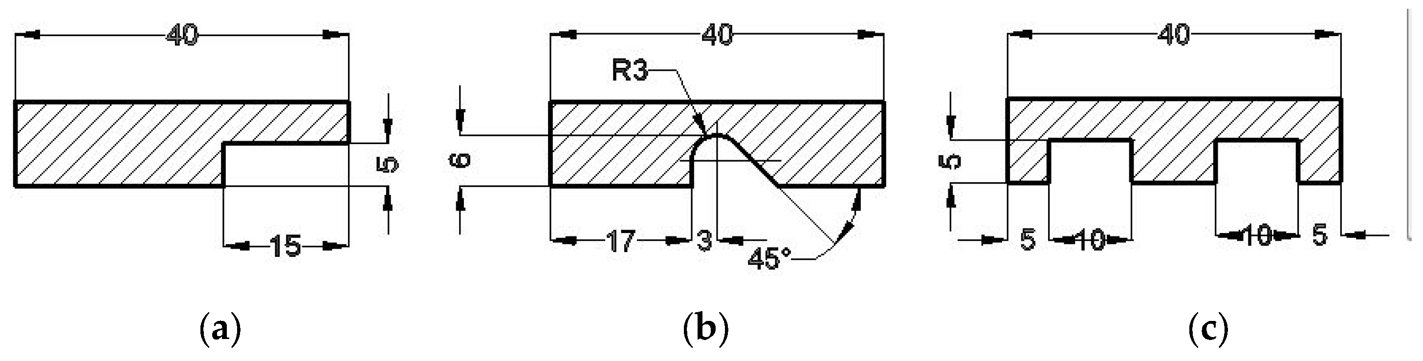
| (a) | 15 | 5 | 10 | 12 | 2.22 | 0.014 | 2.17 |
| (a) 4 | 15 | 5 | 20 | 22 | 2.42 | 0.057 | 9.76 |
| (b) | 10.24 | 6 | 15 | 20 | 5.35 | 0.15 | 9.08 |
| (c) | 10 | 5 | 10 | 15 | 5.25 | 0.012 | 6.23 |
| Profile | Length of Not Tilted Profile (mm) | Length of Tilted Profile (mm) | The Tilting Angle (°) | The Length Increase of the Profile (%) |
|---|---|---|---|---|
| (a) | 15 | 15.73 | 10 | 4.87 |
| (a) 1 | 15 | 15.92 | 20 | 6.13 |
| (b) | 10.24 | 10.46 | 15 | 2.16 |
| (c) | 20 | 20.22 | 10 | 1.10 |
Publisher’s Note: MDPI stays neutral with regard to jurisdictional claims in published maps and institutional affiliations. |
© 2022 by the authors. Licensee MDPI, Basel, Switzerland. This article is an open access article distributed under the terms and conditions of the Creative Commons Attribution (CC BY) license (https://creativecommons.org/licenses/by/4.0/).
Share and Cite
Dragoi, M.-V.; Parv, L.; Mija, A.; Oancea, G. A Method to Design Profiled Cutting Tools for Inner Turning. Symmetry 2022, 14, 2690. https://doi.org/10.3390/sym14122690
Dragoi M-V, Parv L, Mija A, Oancea G. A Method to Design Profiled Cutting Tools for Inner Turning. Symmetry. 2022; 14(12):2690. https://doi.org/10.3390/sym14122690
Chicago/Turabian StyleDragoi, Mircea-Viorel, Luminita Parv, Adrian Mija, and Gheorghe Oancea. 2022. "A Method to Design Profiled Cutting Tools for Inner Turning" Symmetry 14, no. 12: 2690. https://doi.org/10.3390/sym14122690