Review

Phase Sensitivity Improvement in Correlation-Enhanced Nonlinear Interferometers

1
State Key Laboratory of Precision Spectroscopy, Quantum Institute for Light and Atoms, School of Physics and Electronic Science, East China Normal University, Shanghai 200062, China
2
School of Physics, Hefei University of Technology, Hefei 230009, China
3
Shanghai Branch, Hefei National Laboratory, Shanghai 201315, China
4
School of Physics and Astronomy, Tsung-Dao Lee Institute, Shanghai Jiao Tong University, Shanghai 200240, China
5
Shanghai Research Center for Quantum Sciences, Shanghai 201315, China
6
Collaborative Innovation Center of Extreme Optics, Shanxi University, Taiyuan 030006, China
*
Authors to whom correspondence should be addressed.
Symmetry 2022, 14(12), 2684; https://doi.org/10.3390/sym14122684
Submission received: 16 November 2022 / Revised: 11 December 2022 / Accepted: 15 December 2022 / Published: 19 December 2022

Abstract

:
Interferometers are widely used as sensors in precision measurement. Compared with a conventional Mach–Zehnder interferometer, the sensitivity of a correlation-enhanced nonlinear interferometer can break the standard quantum limit. Phase sensitivity plays a significant role in the enhanced performance. In this paper, we review improvement in phase estimation technologies in correlation-enhanced nonlinear interferometers, including SU(1,1) interferometer and SU(1,1)-SU(2) hybrid interferometer, and so on, and the applications in quantum metrology and quantum sensing networks.

1. Introduction

Precision measurement plays a crucial role in developing fundamental ideas in physics. Interferometry, a technique based on wave interference to catch phase shift information, is an irreplaceable and invaluable tool to realize precision measurements [1,2]. The physical quantities, such as small distance, gravity constant, angular velocity, and magnetic fields can all be measured by the interferometric technique. A world-famous project is using the Michelson laser interferometer for gravitational wave detection [3] and other works in the world [4,5]. A typical traditional interferometer consists of three building blocks: splitting light into two paths, phase encoding on one path and recombining two lights to make the encoded phase detectable. The sensitivity of phase measurement for the traditional interferometer, the Mach–Zehnder interferometer (MZI) as an example [6,7,8], is limited by the shot noise limit (SNL) due to the vacuum noise injected into the unused input port, or the so-called standard quantum limit (SQL) for an interferometer with classical fields injected, i.e., Δ ϕ S N L 1 / N , where N is the mean photon number [9,10].
Usually, it is necessary to increase the power of the input laser to improve the measurement accuracy. However, the higher the power, the stronger the radiated noise, resulting in damage to components [11]. To enhance the sensitivity of the phase measurement but not increase the input laser power, on the one hand, a quantum state, such as a squeezed vacuum state, is employed to inject the unused port of the MZI, which was first proposed by Caves [12]. This proposal aims at reducing the shot noise below the vacuum level. If a squeezed vacuum state with squeezed degree r is injected, then the phase sensitivity of MZI can reach 1 / e 2 r N , where the phase sensitivity beats the SNL by a factor of e r . Following this approach for quantum noise suppression, there are several studies to improve the phase sensitivity of the traditional MZI by using different types of quantum states [13,14,15,16,17]. On the other hand, a NOON state or other macroscopically entangled states (Bose–Einstein condensates) are used [18,19,20,21,22,23,24,25,26,27,28,29,30,31,32,33,34,35]. They aim to enhance the phase signal without amplifying noise to super-sensitive phase measurement. The phase sensitivity here can arrive at the Heisenberg limit (HL) Δ ϕ H L 1 / N . Although all the above schemes can improve the phase sensitivity of MZI, these states mentioned are difficult to prepare in an experiment [36,37].
To make the phase sensitivity reach HL, a new type of quantum interferometer scheme, the so-called nonlinear SU(1,1) interferometer (SUI), was proposed by Yurke et al. in 1986 [38]. The term SU(1,1) means that this kind of interferometer performs Bogolyubov transformations of the optical fields [39]. On the contrary, the ordinary traditional linear interferometers perform an SU(2) transformation [40]. In contrast with the conventional MZI with a suitable quantum state injection, SUI can achieve HL with fewer optical elements. It only needs to employ two active optical parametric amplifiers (OPAs), such as four-wave mixers (FWM) or parametric down conversion (PDC), to replace the 50:50 beam splitter (BS) elements in MZI to realize splitting and recombining. This way, it does not need to inject any states, i.e., vacuum state injection. SUI simultaneously utilizes the quantum entanglement produced in parametric amplification (PA) for signal enhancement and quantum noise cancellation.
Up to now, SUI can be realized not only in all-optical [41,42,43,44,45,46,47,48], but also in all-atom [49,50,51,52,53,54,55] and atom–light hybrid [56,57,58,59,60] systems. These systems employ nonlinear Kerr interaction, coherent spin-mixing dynamics (SMD), and Raman effect to realize splitting and combing, respectively. All the evolution operators follow the same SU(1,1) form ( κ a ^ b ^ + κ * a ^ b ^ ) where the modes a and b with strength κ are created or annihilated simultaneously. The all-atom version of SUI in spinor Bose–Einstein condensate (BEC) was first discussed by Gabbrielli et al. [54]. It splits and superposes atomic spin-mixing states in different magneton modes. The experimental realizations can be seen in [49,51,52], etc. This can be also seen in [55] an excellent review written by Pezz e ´ et al. The atom–light hybrid SUI was first proposed and experimentally realized by Chen et al. [56]. Different from the all-optical or all-atom SUI where the interference wave is the light field or atom only, the interference waves of hybrid SUI consist of an optical Stokes field and an atomic spin wave. Such hybrid SUI can be applied to measure the information about the light field and the atomic spin. It is applied in the photon number of the off-resonant light field in the sense of quantum non-demolition (QND) measurement [61,62]. As its name suggests, a parametric amplifier amplifies the intensity of the injected light field, meaning the amplification of the signal and noise. However, the parametric amplifier is also a nonlinear quantum device, generating an entangled quantum state, ‘signal’ and ‘idler.’ The noise of ‘signal’ and ‘idler’ are correlated. In SUI, the two interference arms are ‘signal’ and ‘idler’, respectively. After they combine in the second parametric process, the noise is reduced to the vacuum level at destructive interference due to noise correlation. Thus, the signal in the SU(1,1) is increased while the noise level is not. Due to its special quantum characteristic, the SUI has attracted the attention of researchers successfully. In addition, it can apply in quantum metrology, quantum information, quantum state engineering, and quantum imaging [63,64,65,66,67], especially the ones with the spontaneous parametric down-conversion regime [68,69,70,71]. (See [39,72,73] for latest reviews on SU(1,1) interferometers.)
The original SUI proposed by Yurke is unseeded, resulting in an extremely low total photon number ( N OPA = 2 sinh 2 ξ where ξ is the strength of the OPA) inside the interferometer to feel the phase shift, and that limits the phase sensitivity. To enhance the total phase-sensing photon number, a variation of the SUI with coherent states injected into two input ports was proposed [74]. It showed that the coherent light in the SUI can effectively boost the phase-sensing photon number produced by the first OPA process into a high-intensity regime while the system can still maintain the sub-SNL scaling. Therefore, its phase sensitivity can go beyond conventional MZI, even better than MZI with a squeezed vacuum state injected, where the degree of the squeezed vacuum state is smaller than the amplification factor of OPA. See [75,76] for the experimental demonstration. Later, different input forms, coherent state ⊗ vacuum state, coherent state ⊗ squeezed-vacuum state [77,78], coherent state ⊗ m-photon-added squeezed vacuum state [79], coherent state ⊗ m-coherent superposition squeezed vacuum states [80], thermal state ⊗ squeezed-vacuum state [81], coherent state ⊗ displaced squeezed-vacuum state [82,83], Fock state [84], were studied to enhance the phase sensitivity of SUI at sub-SNL scaling [85,86,87,88,89]. Using a single-mode squeezed state or a squeezed vacuum can both improve the sensitivity of the phase measurement due to the noise reduction, where the usage of a single-mode squeezed state can provide more parameters to realize the flexibility of operation. Moreover, the phase sensitivity of above-mentioned SUIs with a suitable photon number of injected state can reach HL. Taking the coherent state ⊗ squeezed-vacuum state injected as an example, when the amplitude of the input coherent state α and the degree of squeezed-vacuum state r satisfy the condition α = t a n h ( 2 ξ ) e r / 2 , then the interferometer can reach HL.
In addition to inject various seed fields, some variations of SUI were proposed for improving the phase sensitivity. A ‘truncated’ scheme [42,90,91,92,93], introducing one PA process only, saturates the Quantum Cramér–Rao bound (QCRB) and beats the conventional SU(1,1) scheme with a bright seed. A ‘PA + BS’ scheme [94,95,96] turned the second PA process back to BS and can improve the phase sensitivity beyond the SQL. The BS used in this scheme can superimpose the two quantum fields produced by first PA process. When the system operates at the dark point, the noise will be reduced below the vacuum level. Further improvement is possible when a squeezed state is injected into one mode of the first PA. Note that if a BS replaces the first PA process in SUI (‘BS+PA’ scheme), the phase sensitivity cannot improve due to the signal being amplified while the noise is also amplified. More recently, a new type of interferometer was proposed and demonstrated. A SU(2)-in-SU(1,1) nested interferometer [97,98,99,100], nested an MZI in one arm of the SUI, combines the advantages of SU(1,1) and SU(2) interferometry. It can achieve the significant signal strength of SU(2) and the loss-tolerant quantum noise reduction of SU(1,1) to improve the phase sensitivity. An SUI based on two-port feedback nondegenerate OPA [101] has better phase sensitivity than the traditional SUI. It employs two linear BSs to feed the two output beams of the nondegenerate OPA back to its input ports to form the feedback loop. An SUI with nonlinear phase shift [102,103], where a Kerr medium induces the phase shift, shows the significant enhancement of the phase sensitivity and quantum Fisher information (QFI) compared with the linear-phase-shift-based SUI.
Quantum-noise correlation is a beneficial way to enhance phase sensitivity, which is well-proven in SUI by utilizing destructive interference. However, both noise correlation and phase-sensing photon number depend on the system losses, decreasing the phase sensitivity [104]. Hence, studying phase sensitivity mitigation in a lossy environment ranges among the most important topics of current research. The losses can be divided into internal losses (such as photon dissipation) and external losses (such as photodetectors’ quantum inefficiency). Researchers have shown that the SUI in a balanced gain configuration where the gains of PA1 and PA2 are equal can naturally resist the external losses by increasing PAs’ gains, while the phase sensitivity improvement is unlimited. Whereas the phase sensitivity improvement is limited when taking into account the internal losses, such as with the unseeded SUI, it may be impossible to reach the HL or beat the SNL [87]. Recently, unbalanced gain between PA1 and PA2 provides a new opportunity for SUI to resist the internal losses [105,106,107]. Yu et al. summarized the relationship between the internal losses and the gains of PA processes and gave an optimal condition to help the SUI in resisting the internal losses [108]. This optimal condition contains the balanced gain situation and unbalanced gain situation. When the gain of the PA1 and the internal losses are given, phase sensitivity improvement can be achieved by adjusting the gain of PA2 to satisfy the optimal condition. Here, we focus on the enhanced phase estimation performance using various architectures of active beam-splitters SUI. We then review techniques which are resilient to losses.
The structure of the remainder of the paper is as follows. We begin in Section 2 with the basic setup mechanism of SUI compared with MZI. Section 3 reviews the phase sensitivity of SUI with different injection states via different detection methods and presents the QCRB in each situation. Section 4 summarizes the several variations of SUI. Section 5 shows the phase sensitivity improvement technology in lossy SUI via unbalanced gain compared with the balanced gain case. Finally, Section 6 concludes with a discussion of the outlook for phase sensitivity improvement technology of SUI.

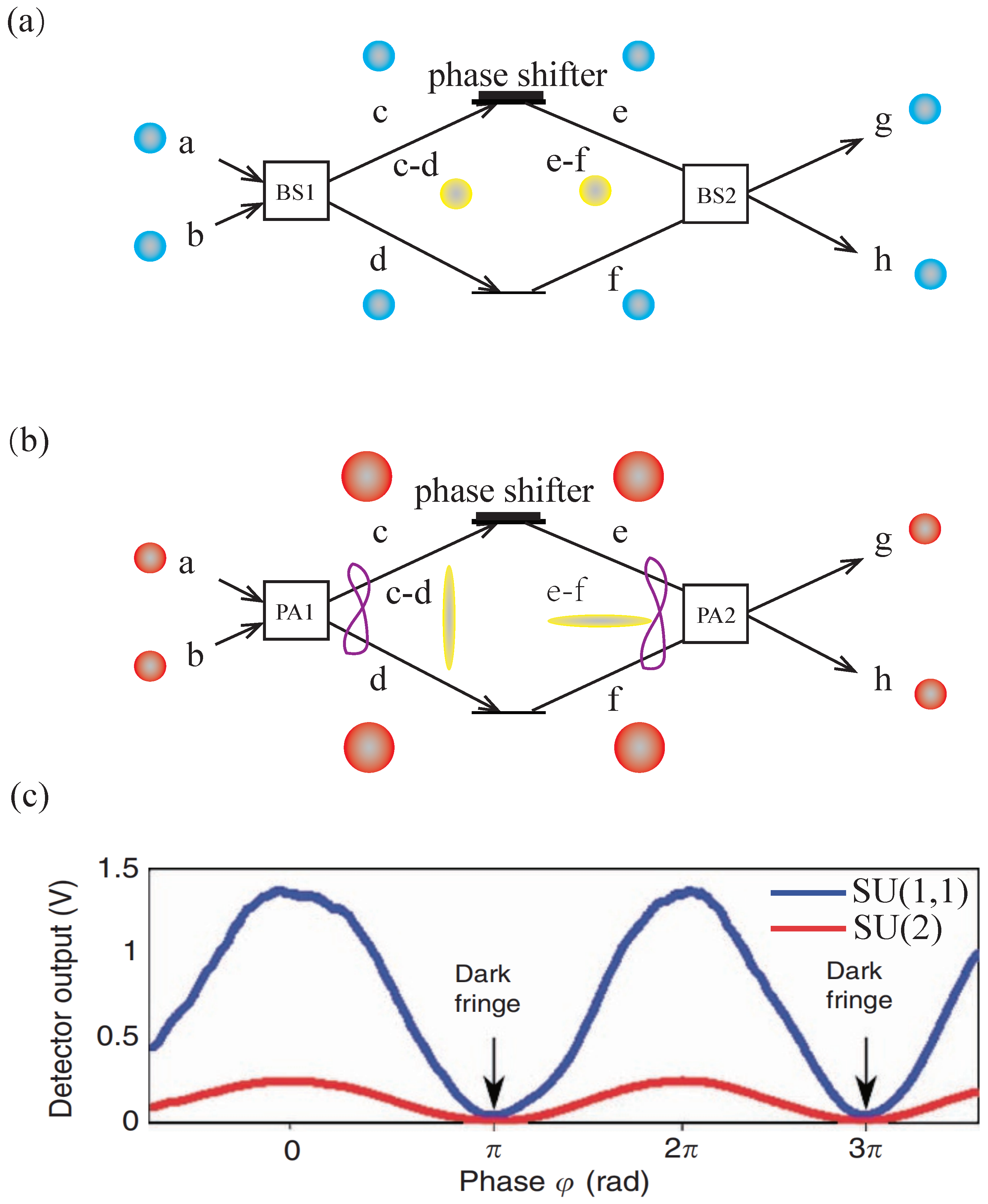
2. SU(1,1) Interferometer vs. SU(2) Interferometer

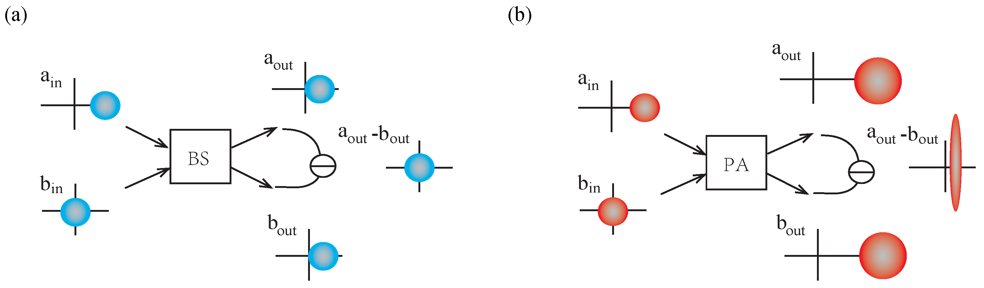
2.1. Input–Output Relations

To establish a nonlinear SUI, one needs to employ two active PAs to replace the traditional linear passive BSs in MZI to realize splitting and combining processes. The BS can be expressed by an operator U ^ B S θ which is a kind of unitary operator being an SU(2) transformation [109] ( U ^ B S θ U ^ B S θ = I )
U ^ B S θ = exp θ ( a ^ b ^ a ^ b ^ ) ,
where a ^ and a ^ ( b ^ and b ^ ) are the annihilation and the creation operators of the BS input port a (b) as shown in Figure 1a, respectively. θ means the degree of splitting ratio. When θ = π / 4 , it applies as a 50:50 BS. From Equation (1), one can calculate the evolution of input state Ψ i n as [110]
Ψ o u t = U ^ B S θ Ψ i n .
Commonly, the input–output relationship of the BS can also be expressed in matrix form,
a ^ o u t b ^ o u t = T R R T a ^ i n b ^ i n ,
where a ^ o u t and b ^ o u t are the annihilation operators of the BS output ports. T and R are the transmissivity and reflectivity of BS with T + R = 1 . In addition, there are other general types of transfer matrix of BS as follows
T i R i R T , T i R R i T .
Here, when a PA replaces the BS, the evolution of the system and the input–output relationship are changed. The PA process can be realized by a degenerate or nondegenerate PDC or FWM process. In nondegenerate cases, the PA process can be described by one strong pump light field with frequency ω p and phase θ p interacts with a nonlinear χ 2 medium which can be a three-level atom or four-level atom or crystal. Then, a ‘signal’ light field with frequency ω s and phase θ s and an ‘idler’ light field with frequency ω i and phase θ i are produced. The frequencies satisfy 2 ω p = ω s + ω i , meanwhile, the phases satisfy 2 θ p = θ s + θ i . These two fields, ‘signal’ and ‘idler’ form a two-mode squeezed state. The time-evolution operator U ^ P A of the nondegenerate PA process can be represented by a two-mode squeezed operator
U ^ P A ξ = exp ξ a ^ b ^ ξ * a ^ b ^ ,
where ξ is some parameter proportionally related by the pump field to the nonlinear coefficient. If the frequencies ω s = ω i , the case corresponds to the degenerate parametric process. Then, the time-evolution operator is described by a single mode squeezed operator U ^ P A ξ = exp ξ a ^ 2 ξ * a ^ 2 .
Of course, the transfer matrix of the PA process has the form
G e i θ p g e i θ p g G ,
where G = cosh ξ and g = sinh ξ are the magnification of the PA progress, and they satisfy G 2 g 2 = 1 . θ p is the phase shift in the PA process.
In the following discussion, we mainly show the nondegenerate PA process results. Taking θ p as 0, and assuming that input states of port a and b are the coherent state α and vacuum state 0 , respectively. The mean photon number of injected coherent state is n a i n = α 2 with α = α e i θ α . After the nondegenerate PA process, the mean photon numbers of output ports are n a o u t = G 2 α 2 + g 2 and n b o u t = g 2 α 2 + g 2 . The difference mean photon number n a o u t n b o u t = α 2 comes from the seed light injection in port a. If α 2 = 0 , it represents the unseeded situation, then n a o u t = n b o u t = g 2 . It can be seen that the intensities of the light fields a and b after the PA process are amplified. Moreover, the intensity variances at output ports are also amplified compared with that under the same photon number of the coherent state, where ( Δ n ^ ) 2 a o u t = G 2 α 2 1 + 2 g 2 + G 2 g 2 and ( Δ n ^ ) 2 b o u t = g 2 α 2 1 + 2 g 2 + G 2 g 2 . Additionally, from the variances of the quadrature components point of view, it has ( Δ X ^ ) 2 o u t = ( Δ P ^ ) 2 o u t = 1 + 2 g 2 , which are larger than the case of coherent state 1. However, the degree of intensity-difference squeezing (IDS) between the two output ports with regard to the SNL [111]
I D S = V a r ( n ^ a o u t n ^ b o u t ) P A V a r ( n ^ a o u t n ^ b o u t ) S N L = 1 2 G 2 1 ,
indicates that the noise of these two output modes is correlated. These two modes form a two-mode squeezed state. The squeezed degree is well dependent on the parametric gain G. In contrast, the BS, as a member of passive devices, rely on the input state and maintain the total number of photons throughout the whole process. The properties of the light field have not changed. Figure 1 shows the noise at each stage in PA and BS processes.

2.2. Phase Measurement

The interferometer is a device that realizes precision measurement by detecting the relative phase shifts which are imprinted in the interference pattern of its output ports. The phase difference between these two arms can be measured by counting the photon number of any output port of the interferometer, and then, the interference pattern is obtained. Commonly, an SUI is formed by two PA processes. The first PA process (PA1 with parametric gains G 1 , g 1 and the phase shift θ 1 ) are used to achieve splitting, while the second PA process (PA2 with parametric gains G 2 , g 2 and the phase shift θ 2 ) are used to combine the light fields propagating on the interference arms to realize interference. Whereas the MZI employs two linear BSs (BS1 with transmissivity T 1 and reflectivity R 1 and BS2 with transmissivity T 2 and reflectivity R 2 ) to achieve splitting and recombining. The diagrams of the SU(2) and SU(1,1) interferometer are shown in Figure 2a,b, respectively.
Using the input–output relations of PA and BS, one can obtain the transmission matrix of the interferometers formed by the creation and annihilation operators of the light field. Assume that the phases of the interferometer arms c and d are φ 1 and φ 2 , respectively. After the calculation, the operators of SUI’s two final output ports g ^ S U 1 , 1 and h ^ s u ( 1 , 1 ) are dependent on the operators of two input ports a ^ and b ^ which are obtained as
g ^ S U 1 , 1 = G 1 G 2 e i φ 1 + g 2 g 1 e i φ 2 + θ 1 θ 2 a ^ + g 1 G 2 e i θ 1 e i φ 1 + G 1 g 2 e i θ 2 e i φ 2 b ^ ,
h ^ s u ( 1 , 1 ) = g 1 G 2 e i θ 1 e i φ 2 + g 2 G 1 e i θ 2 e i φ 1 a ^ + G 2 G 1 e i φ 2 + g 2 g 1 e i φ 1 + θ 1 θ 2 b ^ .
Similarly, the two outputs g ^ S U ( 2 ) and h ^ S U ( 2 ) at MZI are written as (here, we selected the transfer matrix of BS in Equation (3))
g ^ S U ( 2 ) = T 1 T 2 e i φ 1 R 1 R 2 e i φ 2 a ^ + R 1 T 2 e i φ 1 + T 1 R 2 e i φ 2 b ^ ,
h ^ S U ( 2 ) = T 2 T 1 e i φ 2 R 1 R 2 e i φ 1 b ^ R 1 T 2 e i φ 2 + R 2 T 1 e i φ 1 a ^ .
Simply, the interference pattern can be obtained by calculating g ^ g ^ or h ^ h ^ . They rely on the terms a ^ a ^ , b ^ b ^ , a ^ b ^ , a ^ b ^ , a ^ b ^ , which strictly depend on the input fields. It can be seen that different input states lead to different output forms. Select the input state of port a as coherent state with photon number a ^ a ^ = α 2 and input port b as vacuum state with b ^ b ^ = 0 as an example. Then, the photon numbers of output ports g and h are
g ^ g ^ S U 1 , 1 = α 2 + G 2 2 + g 2 2 G 1 2 g 1 2 I p s N C + 2 g 2 G 1 G 2 g 1 cos φ 1 + φ 2 + θ 1 θ 2 I p s N C ,
h ^ h ^ S U 1 , 1 = G 2 2 + g 2 2 G 1 2 g 1 2 I p s N C + 2 g 2 G 1 G 2 g 1 cos φ 1 + φ 2 + θ 1 θ 2 I p s N C ,
where I p s N C = g 1 2 1 + α 2 is the phase-sensing photon number of the SUI. These two output ports are always created or eliminated in pairs by the parametric processes. Note that the output photon numbers depend on the sum of the two arm phases when θ 1 and θ 2 assume certain values and the energy conservation g ^ g ^ S U 1 , 1 h ^ h ^ S U 1 , 1 = α 2 = I i n . The interference visibilities for these two output ports are given as V g = 2 G 2 G 1 g 2 g 1 ( 1 + α 2 ) / [ ( G 2 2 G 1 2 + g 2 2 g 1 2 ) ( 1 + α 2 ) 1 ] and V h = 2 G 2 G 1 g 2 g 1 / G 2 2 g 1 2 + g 2 2 G 1 2 . It can be clearly seen that the larger gain can result in almost perfect visibility for outputs [88,112]. Meanwhile, the h port (‘idler’ field) always has a visibility of 100% when G 2 2 = G 1 2 . Moreover, the photon numbers of MZI at output g and h are
g ^ g ^ S U 2 = T 2 + R 1 R 2 T 1 I p s 2 R 1 R 2 T 2 T 1 cos φ 1 φ 2 I p s ,
h ^ h ^ S U 2 = R 2 + R 1 T 2 T 1 I p s + 2 R 1 R 2 T 2 T 1 cos φ 1 φ 2 I p s ,
where I p s = T 1 α 2 is the phase-sensing photon number of the MZI. It can be seen that the output intensities depend on the phase difference of two interference arms and g ^ g ^ S U 2 + h ^ h ^ S U 2 = α 2 . It is different from the case of the SUI. For simplicity, setting G 1 = G 2 = G , and T 1 = T 2 = 1 / 2 , then the output intensities of SUI and MZI at h port equal to 2 G 2 I p s N C 1 + cos φ and I p s 1 + cos φ where φ is the phase difference in interferometers. When I p s N C = I p s , it can be seen that the output intensity of SU(1,1) is 2 G 2 higher than in the case of MZI. The interference pattern can be obtained by counting the interferometer output port’s photon number when the phase difference is changed continuously from 0 to 2 π . Figure 2c experimentally shows the interference patterns of these two interferometers with the same phase-sensing photon number [41].

3. Phase Sensitivity of SU(1,1) Interferometers

3.1. Phase Sensitivity

The precision of the interferometer for displacement depends on its sensitivity to a small phase shift Δ φ . The relation can be expressed as Δ x = λ 2 π Δ φ where λ is the wavelength of the interference wave. Due to the uncertainty principle, the limit of the interferometer to sensitize the phase shift is 1 / N . This limit is the so-called SQL. Similarly, there is another phase sensitivity limit 1 / N called HL due to the Heisenberg principle. The sensitivity of a phase measurement for a linear interferometer injected coherent state is usually at the SQL. In contrast, the phase sensitivity of the nonlinear SUI with vacuum state input can reach HL [38]. Using the larger number of pump photons in a simple MZI and nonlinear SUI can both improve the absolute phase sensitivities. However, the phase sensitivity of MZI cannot beat the SQL. Under the same number of pump photons, the nonlinear SUI can realize better sensitivity and beat the SQL. Mathematically, the mean-square error in the parameter φ (phase sensitivity Δ φ ) can be given by the error propagation formula as follows
Δ φ 2 = Δ O ^ 2 O ^ / φ 2 ,
where O ^ is the measurable operator of the interferometer’s output port and Δ O ^ 2 =   O ^ 2   O ^ 2 is the variance of operator O ^ . As can be seen from Equation (16), the phase sensitivity of the interferometer depends on the noise of the measured variable and its rate of change for the phase of the interferometer. Commonly, the measured variable can be the photonic number, orthogonal component, parity operator, and product operator of the output ports, corresponding to the intensity detection (ID), homodyne detection (HD), parity detection, and product detection [113].
Now, we introduce the phase sensitivity of SUI using the ID as an example. One can consider the total number of photons at the output of the interferometer, that is,
N ^ T = g ^ g ^ + h ^ h ^ ,
as the variable to be measured to estimate the phase. In a balanced configuration ( G = G 2 = G 1 , g = g 2 = g 1 , θ 2 = θ 1 + π ) and assuming that the two input ports of the SUI are vacuum states with a ^ a ^ = b ^ b ^ = 0 , we can obtain [87]
Δ φ 2 = 1 + 2 1 cos φ g 2 G 2 2 1 + cos φ g 2 G 2 = 1 1 + cos φ 2 N O P A N O P A + 2 + 1 cos φ ,
where N O P A = 2 g 2 is the total number of internal photons created by the first PA process. When the interferometer is operated at destructive interference φ = 0 , the uncertainty Δ φ 2 = 1 / [ N O P A N O P A + 2 ] has a ~ 1 / n 2 scaling characteristic of the HL, which corresponds to the result obtained in [38]. Beside the ID, researchers have shown that the optimal phase sensitivity with parity detection where O ^ = 1 g ^ g ^ can also reach the HL and beat the SNL [114,115].
With the unseeded situation, PA1 produces a low total mean photon number ( N O P A ); these produced photons are not enough for the practical implementation of the scheme. For effectively increasing the total mean photon number, Plick et al. first proposed to inject coherent states into two input ports of SUI while maintaining sub-SNL scaling. Their scheme circumvents the low photon number problem encountered by Leibfried et al. [116] in the experiment. The coherent state in SUI successfully enhances the total mean photon number from N O P A into the high-intensity regime N Tol = N O P A + ( N O P A + 1 ) N α where N α is the total photon number of injected coherent states. It also found that the phase sensitivity of this scheme Δ φ = e 2 r / 2 N α is better than the case of MZI with an injected one-squeezed state Δ φ = e r / N α in the high-gain region. After that, a coherent state ⊗ squeezed-vacuum state was proposed [86]. In this case, the SUI can reach the HL under a suitable condition N α tanh ( 2 ξ ) e r / 2 .
In addition, the thermal state ⊗ squeezed-vacuum state was also used to inject the SUI to study the phase sensitivity [81]. With parity detection, the optimal phase sensitivity is
Δ φ opt 2 = 2 N O P A N O P A + 2 [ 1 + ( 1 + 2 N t h ) ( 1 + 2 sinh 2 r ) ] ,
where N t h is the mean photon number of the injected thermal state. When N t h = ( sinh 2 ξ sinh 2 r ) / cosh 2 2 ξ , the phase sensitivity is approaching the HL. Other types of input states were also analyzed, as reported in [79,80,82,83,84], and so on. The optimal phase sensitivities with different detection methods are shown in Table 1 and are compared with different input cases [113,114].

3.2. Quantum Cramér–Rao Bound

The best possible phase measurement precision is determined using the QFI and the QCRB. The QFI provides a bound on the phase sensitivity that can be achieved by any read-out procedure and is given by [117]
F Q = T r ρ φ L φ 2 ,
where ρ φ = Ψ φ Ψ φ and L φ is the symmetric logarithmic derivative which is defined by ρ φ / φ = [ ρ φ L φ + L φ ρ φ ] / 2 . For a pure state input, the QFI can be simplified to
F Q = 4 Ψ φ Ψ φ Ψ φ Ψ φ 2 ,
where Ψ φ = Ψ φ / φ . The phase sensitivity is related to F Q by the QCRB
Δ φ 1 / F Q .
As shown in Table 1, the phase sensitivity of SUI with injected vacuum states saturates the QCRB. Due to its lower phase sensitivity compared with SNL, SUI becomes a new star to achieve precision measurements.

3.3. Signal Enhanced and Noise Reduced by Destructive Quantum Interference

The sensitivity of phase measurement for SUI is more sensitive than in the case of MZI due to the amplification of the PA process in SUI. Here, one can argue whether the phase sensitivity is enhanced if the parameter amplifier is placed at MZI. The answer is correct but using correlated injection [118]. It is well known that the parameter amplifier amplifies not only the signal but also the noise. Sometimes the noise increases more than the signal. So, using an amplifier in MZI, at best, one reaches SQL. However, using correlated injection, the phase sensitivity can beat the SQL [85,119]. The keys are intensity amplification (amplifying phase-sensing intensity) and quantum noise correlation (squeezing shot noise). The larger the parametric gain, the more phase sensitivity improvement.
In SUI, the parametric amplification process based on three-wave or four-wave mixing process does not amplify the noise as much as the signal, leading to enhanced sensitivity of the phase shift. The PA1 produces two mode-squeezed states ‘signal’ and ‘idler’. These two modes propagate at the two arms of the SUI, respectively. They are quantum-mechanically entangled, and their noises are correlated (see Section 2.1). When they pass through the PA2 simultaneously, the noise of the output port becomes
V a r X = 1 + 4 G 2 g 2 1 cos φ .
When the interferometer is operated at the dark fringe, φ = 0 , the noise reduces to 1, meaning that most of the amplified noises from PA1 are canceled, and only vacuum noise is left by destructive quantum interference. Meanwhile, the fringe size of SUI is increased by a factor of 2 G 2 (see Section 2.2). Therefore, the SUI increases the signal while it keeps the noise at the vacuum level, leading to an enhancement in signal-to-noise ratio for phase measurement compared to the MZI [76]. The noise relation can be seen in Figure 2a,b.

4. Various Types of SU(1,1) Interferometers

Not only can the all-optical system (such as circuit quantum electrodynamics system [120] or fiber system [121]) build an SUI, but also, in the all-atom, the light–atom hybrid can form SUI. Unlike the all-optical type of SUI, where FWM or PDC knows the beam-splitting and combining process, the atomic SUI employs the spin-mixing dynamics as the nonlinear process to realize the splitting and combining process. At the same time, the light–atom hybrid SUI takes the Raman effect to achieve the splitting and combining process. All interaction Hamilitions are similar to that of the PA process. The phase sensitivities of these types of SUI share the same expression as shown above. One feature of these various types of SUI is that the interference waves are different. In all-optical or all-atom various SUI, the interference wave is a light field or atom wave, meaning that they can only measure the physical quantity sensitive to the light field or atom. In contrast, the interference waves consist of the light field and atom in a light–atom hybrid SUI, meaning that this hybrid SUI can measure both sensitive physical quantities.

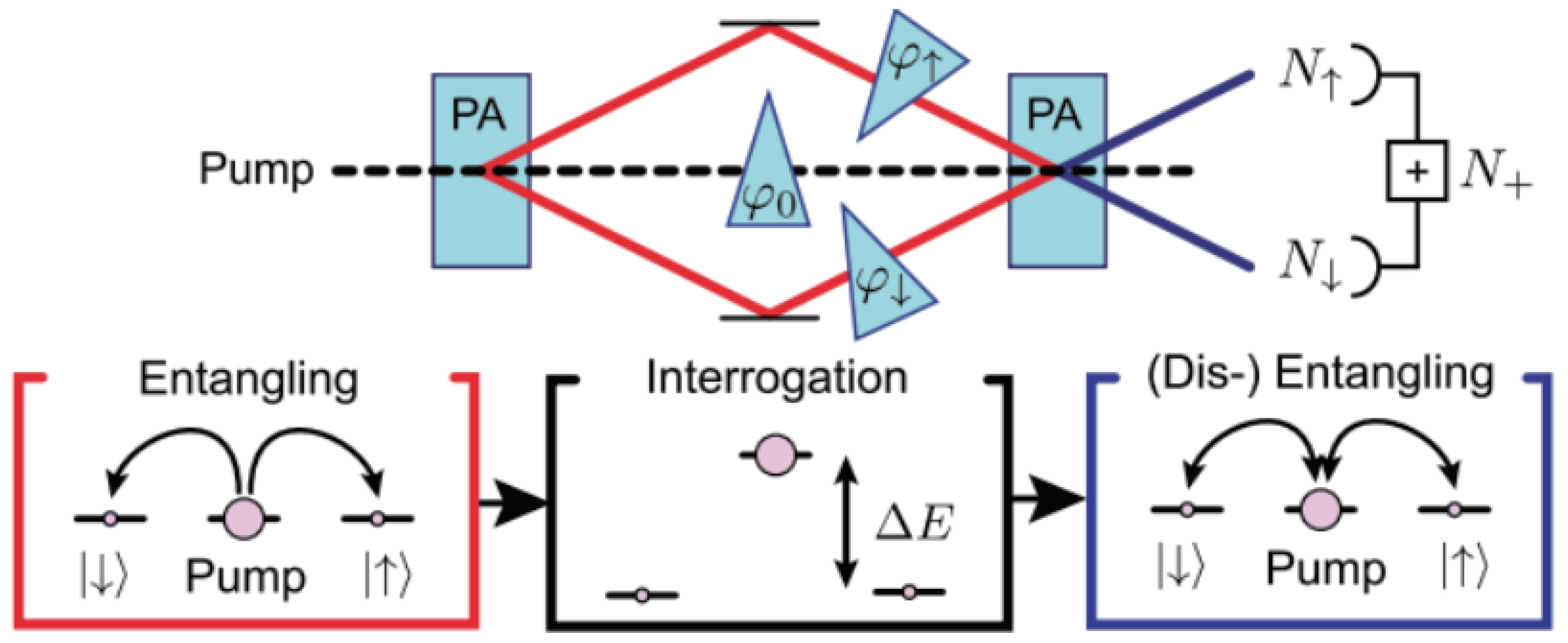
4.1. Atomic SU(1,1) Interferometer

The atomic SUI was first discussed by Gabbrielli et al. in 2015 [54], and then, an experimental demonstration was given by Linnemann et al. in 2016 [49]. Later, experimental studies were reported in [51,52], etc. The schematic of the atomic SUI is shown in Figure 3. It divides into three building blocks: entangled state preparation, interrogation, and nonlinear time reversal for read out. In this kind of SUI, the Spin-changing collisions in a Bose–Einstein condensate are used as the nonlinear parametric process to achieve splitting and combining process, where the corresponding Hamiltonian
H ^ = κ a ^ a ^ + H . c . ,
in which a ^ ( a ^ ) denotes the creation operator for the signal mode = F = 2 , m F = 1 (idler mode = F = 2 , m F = 1 ) in 87 Rb. The signal and idler modes are also called the side modes. is the reduced Planck constant, and κ = g N 0 is the effective nonlinear coupling strength. g is the microscopic nonlinearity, and N 0 is the number of atoms in the pump mode F = 2 , m F = 0 . After the first Spin-changing collisions, the entangled state produced in this scheme is described by Ψ = n = 0 p n n n , where p n = N n / 1 + N n + 1 . N = N = sinh 2 κ t is the mean atom number in either mode after evolution time t. Due to the pairwise scattering during the spin exchange, the side modes are perfectly correlated. During interrogation, the signal mode accumulates the total phase n φ , and the idler mode accumulates the total phase n φ , such the probe state becomes Ψ = n = 0 p n e i n ( φ + φ ) n n . To determine the unknown phase φ + φ , the second Spin-changing collisions are working. The second Hamiltonian evolution is characterized by a nonlinear coupling strength κ e i φ κ , where φ = 2 φ 0 ( φ + φ ) is the spinor phase and φ 0 is the pump mode phase. One can reverse the evolution H H for the best sensitivity if the phase φ 0 satisfies 2 φ 0 = π + ( φ + φ ) .

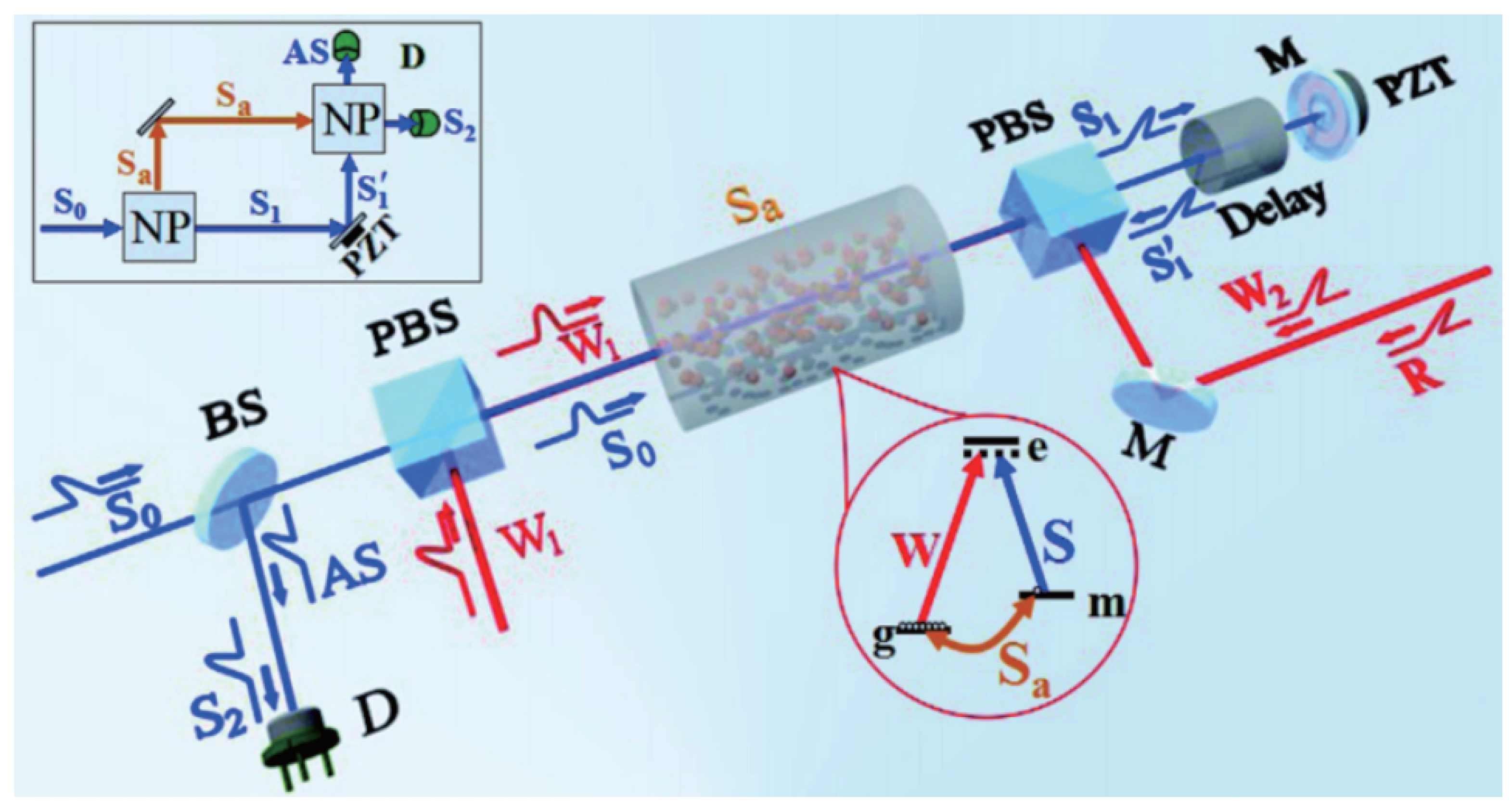
4.2. Atom–Light Hybrid SU(1,1) Interferometer

In 2015, an atom–light hybrid SUI was first proposed by Chen et al. [56]. It couples different types of waves for interference by atomic Raman amplification processes. One interference wave is a Stokes field and the other is the atom spin wave. The atomic Raman amplification processes can be expressed as an ensemble of N a identical Λ -type hot Rb 87 atoms interacting with two fields, a strong Raman pump field W and a Stokes field S. The strong Raman pump field couples the atomic energy level g e (5 2 S 1 / 2 F = 1 5 2 P 1 / 2 F = 1 ) while the Stokes field S couples the atomic energy m e (5 2 S 1 / 2 F = 2 5 2 P 1 / 2 F = 1 ), producing a collective atomic excitation field S a 1 / N a k g k m . These three fields are coupled via an upper excited level e . Under adiabatic approximation, the time-evolution operator U ^ R of the stimulated Raman scattering process is given by
U ^ R = exp η A w a ^ s S ^ a η * A w * a ^ s S ^ a ,
where η = t g e g g e m / Δ with g e g and g e m are the coupling coefficients between the light fields and atom, Δ is detuning from the excited state for both the Stokes and Raman write fields. A w is the amplitude of the Raman pump field, a ^ s ( a ^ s ) is the creation (annihilation) operator of the Stokes field, and S ^ a ( S ^ a ) is the creation (annihilation) operator of the atom spin field. Here, the pump field A w is relatively strong such the input Stokes field will be amplified. The amplified Stokes field and the produced atomic spin wave are phase-correlated. Note that the expression (25) has the same form as the SU(1,1) Hamiltonian in Equation (5) for the PA process. The Stokes field can be regarded as the ‘signal’ field, and the atom spin wave can be treated as the ‘idler’ field. Hence, just like the all-optical SUI, the atom–light hybrid interferometer employs nonlinear atomic Raman amplification processes replacing the beam-splitting and combing elements in a traditional interferometer. The schematic diagram is shown in Figure 4. This kind of nonlinear atom–light hybrid interferometer is sensitive to the light field and atomic state, which can be widely used in precision measurement and quantum control with atoms and photons.

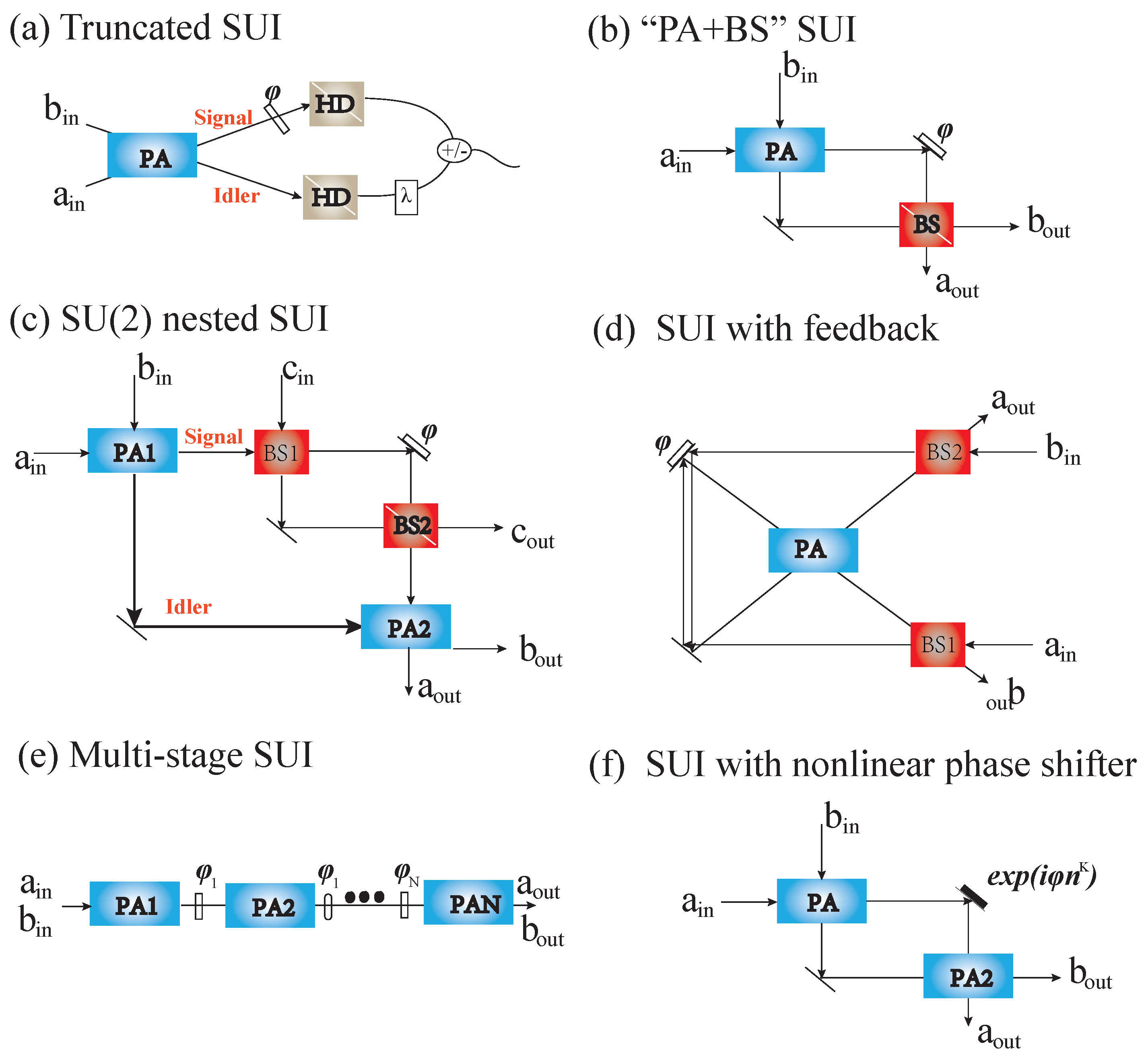
4.3. Deformation of Nonlinear SU(1,1) Interferometers

Unlike the traditional SUI where one PA is employed to split and the other PA is used to combine, there are the deformations of SUI that were proposed, such as truncated types of SUI, PA + BS types of SUI, SU(2) nested SUI, SUI with a feedback mechanism, multi-stage SUI, and SUI with nonlinear phase shifter. These types of SUI are shown in Figure 5. In the following, we introduce these types of interferometers.

4.3.1. Truncated SU(1,1) Interferometer

A truncated SUI which can achieve the same phase sensitivity as that of a traditional SUI was proposed by Brian E. Anderson et al. [90]. The map of the truncated SUI is shown in Figure 5a. The idea of building a perfect truncated SUI is taking the second nonlinear PA process out and then directly detecting the probe and conjugate beams via HD or ID, respectively. When it takes HD, the phase sensitivity can saturate the QCRB. This scheme can eliminate the losses for imperfect mode-matching of the beams and absorption in the medium that come from the second nonlinear process in the traditional SUI. Moreover, it provides a simpler means to achieve quantum-enhanced phase sensitivities and is more easily implemented in an experiment. Recently, the measurement of the displacement of an atomic force microscope microcantilever has been realized in truncated SUI [92].

4.3.2. PA + BS Type of SU(1,1) Interferometer

In a traditional nonlinear SUI, many photons are absorbed in the beam combining process, resulting in limited phase sensitivity. To boost the photon number, a deformation of the SUI with a degenerate PA for beam splitting and a BS for wave superposition and interference (called PA + BS scheme) was studied [94]. This scheme is shown in Figure 5b. Consider a vacuum state and coherent state with amplitude α injection, one output noise is related to the gain of the PA process by 1 / 2 g 2 + G 2 when the transmissivity of BS T = g 2 + G 2 2 / 8 g 2 G 2 + 1 , and then, the optimum phase sensitivity is obtained
Δ φ o p t = 1 4 I p s N L g 2 + G 2 = S Q L 2 G ,
where I p s N L = g 2 α 2 . It shows that the scheme of PA + BS improves upon the SQL by a factor of 2 G and the noise level of this scheme is reduced below the vacuum noise level by 2 g 2 + G 2 . Compared with PA + PA, whose phase sensitivity improvement is due to the signal increase, here, the phase improvement is from noise reduction for PA + BS.

4.3.3. Phase-Sensing Amplified SU(2)-SU(1,1) Hybrid Interferometer

It is well known that the phase sensitivity of a nonlinear SUI can break the SQL. However, the phase-sensing photon number stimulated by the first PA process is limited and is mostly too small, which imposes constraints on the enhancement measurement. Seeding can be used to increase the number of phase-sensing photons, and therefore, the overall sensitivity [122]. However, the uncorrelated noise grows when the intensity of the seed light increases for the limitation of the PA process; the result also imposes a disadvantage on the enhancement measurement.
One technique to enhance the phase-sensing photon number in SUI is proposed by [97]. It employs an MZI where the MZI is nested inside one arm of the SUI, as shown in Figure 5c. The ‘signal’ beam from the PA1 is injected into the dark input port of the MZI, while an extra bright coherent state with amplitude α is fed into the bright input port of the MZI. The one output port of the MZI and the ‘idler’ beam are combined at PA2. This model can also be considered as an MZI in which a coherent state is injected in one input port and one mode of a two-mode squeezed state is injected in another input port, and takes active correlation output readout. The phase shift to be detected is encoded in one arm of the MZI. When the MZI operates at the dark point, the amplitude of MZI output is about α φ , corresponding to the phase-sensing photon number of this hybrid scheme boosted by the strong coherent state magnitude α . It is a noiseless copy of the dark input when MZI works at the dark output. In this way, SU(2)-SU(1,1) hybrid interferometer can achieve the large signal strength of MZI and the loss-tolerant quantum noise reduction of the SU(1,1) approach. In a balanced configuration, the phase sensitivity can beat the SQL ( Δ φ S Q L = 1 / N α + 2 g 2 ) by a factor of G when R / T = 1 . A path-length sensitivity with SNR 2.2 dB beyond the SQL at power levels 2 orders of magnitude beyond those of the previous loss-tolerant interferometer was observed in an experiment [99].

4.3.4. SU(1,1) Interferometer with Feedback and SU(1,1) Interferometer with Multi-Stage

It is well known that phase sensitivity can be improved by increasing the gain of PAs. However, such improvement cannot be infinitely significant because of the saturation of parametric amplifiers. Usually, the PA is located at a low-gain regime, resulting in the absolute phase sensitivity of the SUI that cannot be much higher than MZI. Meanwhile, the quantum correlation between two beams is also limited. Feedback, which can enhance the relative intensity squeezing between two or three beams [123,124,125], is employed to improve SUI absolute phase sensitivity at a given finite gain of the parametric amplifiers [101]. The schema is shown in Figure 5d. It combines one nondegenerate OPA and two BSs. The two output beams of the OPA are fed back into two input ports via BS1 and BS2, respectively. This creates two structures of feedback loops. The phase shift is encoded in one feedback loop. The transmissivities of BS1 and BS2 are denoted by k and l. For simplicity, k = l. Research showed that the performance of this kind of interferometer is extremely dependent on the transmissivity of the BSs [101]. Considering one port is seeded by a coherent state while the other port is in a vacuum and taking direct ID to measure the one output port, the phase sensitivity can go beyond both the SQL and traditional SUI when k has a suitable value (e.g., 0.6 < k < 0.9). However, when k < 0.4, the phase sensitivity is worse than SQL and that of the SUI. One can explain that the times of the PA process are infinite under the feedback structure, which is very different from the SUI made by two OPAs. For each PA process, the ‘signal’ and ‘idler’ beams are always correlated, and additional noise is not produced. Hence, it can further amplify the advantages of the SUI.
For a particular feedback structure, the times of the PA process increase. Here, it is a multi-stage SUI that adds multiple PAs to form, as shown in Figure 5e [126,127,128]. It is similar to the SUI with feedback in which both times of the PA process increase. The difference between these two kinds of SUIs is that the multi-stage SUI works in a low-gain limit so that spontaneous emission dominates and two-photon states are generated. Multi-stage SUI were also experimentally demonstrated in [129,130].

4.3.5. SU(1,1) Interferometer with Nonlinear Phase Shifter

In addition to the nonlinear PA process, a nonlinear phase shifter has also been proposed for enhancing the phase estimation, which can be viewed as another method of probe modification [102,103]. The model can be seen in Figure 5f. A nonlinear phase shifter can be achieved by the third-order susceptibility of the Kerr medium, corresponding to the evolution operator
S ^ φ , k = exp i φ n ^ k ,
where φ is the phase difference between two arms and n ^ is the phase-sensing photon number. When k = 1 , S ^ φ , k reduces to the traditional linear phase shift case. When k = 2 , S ^ φ , k corresponds to Kerr nonlinear case. Via HD, the phase sensitivity of the SUI with nonlinear phase shifter and balanced gain at optimal point φ = 0 has the form
Δ φ 2 = Δ φ 1 1 + N O P A 2 + N α ,
where the phase sensitivity of traditional SUI with a linear phase shift is Δ φ 1 = 1 / N O P A N α . It can be seen that Δ φ 2 < Δ φ 1 , corresponding to enhanced phase sensitivity.
In addition, there is a new idea to enhance the phase sensitivity of the SUI by using photon level operations (PLOs) seen in [131].

5. Phase Sensitivity Improvement via Gain Unbalance in Lossy Interferometers

It is significant to study the effect of losses on phase sensitivity. There are two types of losses: inside and outside the interferometer. Only a loss-resistant interferometer can be more widely used.
It is well known that the measurement quality of MZI is reduced quickly in the presence of external losses [132]. For the LIGO project with a coherent state ⊗ squeezed-vacuum state input, for example [133], 10.3 dB of squeezing is injected, resulting in only 2.2 dB of squeezing that can be measured due to loss, meaning that the losses of the linear interferometer limit the enhancement in phase sensitivity. Solving this problem requires perfect or almost perfect detectors to obtain a sensitivity below the shot noise limit.
Contrarily, researchers have shown that the SU(1,1) scheme with gain balance ( G = G 2 = G 1 , g = g 2 = g 1 ) is not as sensitive to external loss as the linear scheme with a squeezed state for noise reduction. Even though external losses reduce the sensitivity of the SUI, the external loss does not prevent SUI from beating the SQL and does not change the scaling characteristic of the HL. Consider that the effect of the detection efficiency marked by the notation η as transmissivity, the phase sensitivity with external loss from Equation (18) becomes
Δ φ l 2 = 1 + η 2 η Δ φ 2 .
Showing the effect of the detector efficiency is to reduce the sensitivity by introducing an overall prefactor 1 + η / 2 η , which can be eliminated by increasing the gains of the PAs G , g . The larger the gain, the more resistant to extra loss [85,87]. Thus, making phase sensitivity small, it is still possible to maintain the HL scaling. From this, the SUI is robust against external losses. So does the other state injection. The phase sensitivity can resist external loss by adjusting gains [87].

5.1. Normal All-Optical SU(1,1) Interferometer

In fact, the phase sensitivity of the SUI is susceptible to internal losses. When the internal loss is introduced, the symmetry of the SUI is broken, and the resulting balanced configuration of the SUI is not optimal for resisting external loss. Here, unbalanced gain gives an additional degree of freedom to optimize the properties of the SUI to reduce the effect of external losses when the internal loss is introduced. M. Manceau et al. pointed out that a broader super-sensitivity phase range and a better overall sensitivity can be achieved at gain unbalancing, as shown in Figure 6, where the internal loss is 0.1 and the first PA’s gain equals 1.15 . Figure 6 shows that increasing the gain of the second PA can lead to better sensitivity and a broader super-sensitive phase range [105]. Meanwhile, the balanced case G 1 = G 2 = 1.15 does not provide phase super-sensitivity even for the external lossless case seen in Figure 6a. The sensitivity improves as one increases the gain of the second amplifier. The experiment has verified that the phase super-sensitivity of an unseeded degenerated, nonlinear unbalanced interferometer on direct detection can be preserved even with detection losses as high as 80% by increasing the gain of the PA2 [43].
The above results are applicable when the internal loss is definite. When the internal loss is variable, things are changed. Figure 7a shows the effect of the internal loss R d on the inverse Fano factor N d , min / Δ N d , min 2 and Figure 7b the effect of the internal loss R d on the optimal phase sensitivity Δ φ d , min 2 in the absence of external loss. The lower the inverse Fano factor N d , min / Δ N d , min 2 , the more resistant it is to external loss. As seen in Figure 7a, increasing the gain of the second PA indeed can reduce the external loss effect. However, for sufficiently large internal loss, the balanced situation is better than the unbalanced gain situation.
The optimal phase uncertainty of degenerate SUI in unbalanced gain configuration has the following form when taking both external and internal losses off
Δ φ opt 2 = 1 2 G min 2 g min 2 ,
where G min = min [ G 2 , G 1 ] is the smaller parameter. g min = min [ g 2 , g 1 ] is defined in the same way. In this configuration, the form of the optimal phase sensitivity (30) is the same as in the balanced case Δ φ opt 2 = 1 / 2 G 2 g 2 . The difference is that the phase sensitivity (30) here is limited by the PAs with smaller gain, independent of whether it is PA1 or PA2.
When considering the internal loss which can be described by a BS with transmittance T d and reflectance R d , the optimal phase sensitivity Δ φ opt 2 = 1 / 2 G min 2 g min 2 here is still valid, where now g min 2 = min [ g 1 2 T d , g 2 2 ] and G min 2 = min [ 1 + g 1 2 T d , G 2 2 ] are the new definitions. If g 1 2 T d > g 2 2 , it means g 2 = g min , the phase uncertainty Δ φ opt 2 is only limited by the PA2 and independent of the internal loss. Thus, if the internal loss dominates, it is better to have a stronger PA1 than PA2 to resist the internal loss, as shown in Figure 7b. Moreover, for sufficiently small internal loss, the balanced gain situation is better than the unbalanced gain situation to resist the internal loss. To sum up, a stronger PA2 can effectively reduce the effect of detection loss, while a stronger PA1 can effectively inhibit the influence of internal loss. One can accord to the state of the system to decide whether a stronger PA1 or stronger PA2 is used.

5.2. Atom–Light Hybrid SU(1,1) Interferometer

Leading from the above discussion, Yu et al. provided an optimal condition for the atom–light hybrid interferometer to resist internal loss when taking ID given by [108]
G 1 G 2 1 l = g 1 g 2 1 η ,
where l is the loss rate of the Stokes beam and η is the loss rate of the Spin wave beam. This optimal condition applies to any various traditional SUI. It is about the optimal allocation relationship between the gain of the PA1, the gain of the PA2, and the internal losses. The SUI can resist internal losses when these parameters satisfy the optimal condition.
The visibility V S U is given by
V S U 2 G 1 G 2 g 1 g 2 1 l 1 η G 1 2 G 2 2 ( 1 l ) + g 1 2 g 2 2 ( 1 η ) .
One perfect visibility in the output port requires the same intensities of the two interference arms after final amplification. With the internal losses, there is one Stokes beam G 1 1 l and the Spin wave beam g 1 1 η . After the second PA process and view on the output port g, the signal beam is amplified to G 2 G 1 1 l while the idler beam is amplified to g 2 g 1 1 η . When G 2 is adjusted to satisfy Equation (31), i.e., the optimal condition holds, the amplitudes of these two beams are equal, resulting in the visibility of the output port that can always reach ∼100% even if the internal loss is large. Figure 8a–c has shown some theoretical examples, where G 1 and internal losses l and η are defined. After modulating G 2 to satisfy the optimal condition, the visibility of the atom–light hybrid interferometer improves from the blue line curve (without optimal the parameter G 2 ) to the red dashed curve, corresponding to a perfect visibility obtained. Figure 9 shows the experimental result on the visibility of SUI before and after optimization.
The improved visibility corresponds to the improvement of the sensitivity of the phase shift. Of course, when optimal visibility is obtained, the best signal-to-noise ratio (SNR) can be achieved. SNR can be calculated by the equation
S N R = O ^ / φ δ 2 Δ O ^ 2 ,
where δ is an small added modulation phase. When S N R = 1 , the added modulation δ represents the minimal phase sensitivity Δ φ . Figure 8d–f shows the SNR of the SUI before and after optimization G 2 and the SNR of the MZI with the same parameters theoretically. It can be seen in Figure 8d–e that the SNR can beat the SNL (solid black line) in an extensive range of internal losses after optimizing G 2 (red dashed curve). As long as the parameter G 2 satisfies the optimal condition (blue box), the system can resist the internal loss, and the sensitivity of the phase increases. However, when the internal loss η = 0.8 is significantly large, as seen in Figure 8f, this advantaged range gradually diminishes.
It is well known that the noises in the two arms of the SUI are correlated, leading to the noise cancellation cleanly to the vacuum level at the output of the SUI. However, the quantum-noise correlation strictly depends on the internal losses. When the internal loss is introduced, the quantum-noise correlation will be destroyed, and the uncorrelated noise will appear. After the second PA process, the uncorrelated noise will be amplified, thus reducing the phase sensitivity. Here, the condition of Equation (31) can almost completely cancel the correlated noise from the two arms in the output light field; then, the visibility and the SNR of the output light field will be optimal. When the internal losses become larger, it will bring more uncorrelated excess noise and quickly reduce the noise cancellation advantage of the SU(1, 1)-type interferometer. However, Equation (31) can handle it.
Taking HD, Yu et al. also provided an optimal condition for internal loss resistance as follows:
2 1 l 1 η G 1 G 2 g 1 g 2 = 2 1 η g 1 2 g 2 2 + g 2 2 + G 2 2 .
It differs from the optimization condition (31). When the parameters ( G 1 , 2 , g 1 , 2 , l , η ) match the above optimal conditions, the SUI can resist any internal losses, and then, the phase sensitivity can be improved.

5.3. SU(2) Nested SU(1,1) Interferometer

In the model of SU(2) nested various SUI, Jiao et al. also studied the effects of losses on the phase sensitivity via gain unbalance [98]. When the two input ports of the SU(1,1) interferometer have no injection and under HD at the dark point, the optimal sensitivity in the absence of losses can be obtained as follows
Δ 2 φ o p t H D = 2 G 2 g 1 G 1 g 2 + 1 4 T R G 2 2 N c ,
where R = R 1 = R 2 ( T = T 1 = T 2 ) is the reflectivity (transmissivity) of the BSs in SU(2) interferometer. N c is the total mean photon number of the input coherent state in the SU(2) interferometer. From the expression (35), Jiao et al. gave an optimal condition
g 2 / G 2 o p t = 2 G 1 g 1 / 2 G 1 2 1 ,
for Δ 2 φ o p t H D that can always reach the optimal value. This optimal condition consists in all possible relations between ( G 1 , g 1 ) and ( G 2 , g 2 ). When G 1 is definite, there is an optimal G 2 to obtain optimal phase sensitivity. There is a special case when G 2 / G 1 2 and the phase sensitivity always reaches the QCRB.
Taking into account the internal losses and the external losses, Jiao et al. also gave an optimal condition:
g 2 G 2 o p t = G 1 g 1 η a η b T η d + R η c η a G 1 2 + 1 η a 1 / 2 ,
where η a and η b are the external transmission rates of the MZI, and η c and η d are the internal transmission rates of the MZI. The above Equation (37) indicates how the gain ratio to loss mitigation can be adjusted. Figure 10 shows the effect of external losses and internal losses on the phase sensitivity after optimized G2/G1. The phase sensitivities in the area of the upper right corner and within the SQL lines in Figure 10 can beat the SQL. The black solid lines (SQL0) denote the SQL when G 2 = G 1 , and the red dotted lines (SQL1) denote the SQL with optimized G 2 . As seen in Figure 10, the area within the SQL1 line is larger than the area within the SQL0 line, which implies that via optimizing ( G 2 / G 1 ) , one can provide a new window for a system to resist the losses. This is a new change that cannot be brought from the balanced gain situation.

6. Outlook

The SUI has attracted steady and growing interest over several decades because it is highly sensitive to phase shift measurement and its robustness to losses. Firstly proposed in 1986, several variations of the seeded SUI emerged, and now, there are various types of SUI. Such nonlinear active interference devices can contribute to metrology [41,99], and imaging [134,135,136], and be embedded in most platforms, for example, the infrared and THz refractometry [137,138], and the infrared polarimetry [139]. Their robustness to losses promotes them as an attractive candidate to quantum-enhanced real-world applications in the near term. Here, we have summarized the phase sensitivity improvement technology by adjusting the gain coefficient in the presence of losses. This technology provides a new image and can be applied to many losses. Following this thought, one can focus on these general stages: (i) probe generation, such as injecting a suitable field, including the coherent state and squeezed vacuum state, (ii) probe modification, such as deformation of SUI, including SU(2)-in-SU(1,1) nested interferometer, (iii) phase information readout, such as selected HD or ID method, and so on, to improve the phase sensitivity further.

Author Contributions

Conceptualization, W.Z., L.C. and C.-H.Y.; investigation, X.L. and Z.Y.; writing—original draft preparation, X.L.; writing—review and editing, L.C. and C.-H.Y.; supervision, C.-H.Y.; project administration, L.C. All authors have read and agreed to the published version of the manuscript.

Funding

This work is supported by the National Natural Science Foundation of China Grants No. 12274132, No. 11874152, No. 11974111, and No. 91536114; Shanghai Municipal Science and Technology Major Project under Grant No. 2019SHZDZX01; Innovation Program of Shanghai Municipal Education Commission No. 202101070008E00099; Innovation Program for Quantum Science and Technology No. 2021ZD0303200; and Fundamental Research Funds for the Central Universities.

Institutional Review Board Statement

Not applicable.

Informed Consent Statement

Not applicable.

Data Availability Statement

Not applicable.

Conflicts of Interest

The authors declare no conflict of interest.

Abbreviations

The following abbreviations are used in this manuscript:
MZIMach–Zehnder interferometer
SNLShot noise limit
SQLStandard quantum limit
HLHeisenberg limit
SUISU(1,1) interferometer
OPAOptical parametric amplifier
FWMFour-wave mixing
PDCParametric down-conversion
BSBeam splitter
SMDSpin-mixing dynamics
BECBose–Einstein condensate
QNDNon-demolition measurement
QCRBQuantum Cramér–Rao bound
QFIQuantum Fisher information
IDSIntensity-difference squeezing
IDIntensity detection
HDHomdyne detection
PLOPhoton level operation
SNRSignal-to-noise ration

Appendix A

The expression of Δ φ I , coh , Δ φ coh , Δ ϕ I , coh & Sqz , and Δ ϕ Sqz & Sqz in Table 1 are shown as follows
Δ φ I , coh = [ csch 4 ( 2 ξ ) ( sec 2 ( φ / 2 ) ( ( 2 N α + 1 ) cosh ( 8 ξ ) 1 ) + 2 N α csc 2 ( φ / 2 ) ) 8 ( 2 N α + 1 ) ] 1 / 2 [ 2 2 ( N α + 1 ) ] 1 ,
Δ φ coh = 4 ( cosh 2 ( 2 ξ ) sinh 2 ( 2 ξ ) cos ( φ ) ) 2 ( ( cosh 2 ( 2 ξ ) sinh 2 ( 2 ξ ) cos ( φ ) ) 2 × exp [ 4 N α e 2 ξ ( sinh ( 2 ξ ) cos ( φ ) + cosh ( 2 ξ ) ) cosh 2 ( 2 ξ ) sinh 2 ( 2 ξ ) cos ( φ ) ] 1 ) 1 / 2 × sinh ( 4 ξ ) sin ( φ ) sinh ( 4 ξ ) 4 N α 2 sinh 4 ( 2 ξ ) sin ( 2 φ ) 1 ,
Δ φ I , coh & sqz = [ sech 4 ξ csc 2 φ ( 32 ( cosh ξ + cosh ( 3 ξ ) ) 2 csch 2 ξ cos φ ( 4 e 2 r N α + cosh ( 4 r ) 1 ) 8 coth 2 ξ cos ( 2 φ ) ( 4 sinh 2 ( 2 ξ ) ( 4 N α cosh ( 2 r ) + cosh ( 4 r ) 1 ) 8 N α ( cosh ( 4 ξ ) + 3 ) sinh ( 2 r ) ) 64 N α ( 3 cosh ( 4 ξ ) + 5 ) coth 2 ξ cosh ( 2 r ) + 64 N α ( 3 cosh ( 4 ξ ) + 1 ) coth 2 ξ sinh ( 2 r ) 2 ( 4 cosh ( 4 ξ ) + 3 cosh ( 8 ξ ) + 9 ) × csch 4 ξ sinh 2 ( 2 r ) ) ] 1 / 2 [ 16 ( 2 N α + cosh ( 2 r ) ) ] 1 ,
Δ φ Sqz & Sqz = ( 1 / 2 2 ) csch ( 2 ξ ) sech ( 2 r ) ( csch 2 ( 2 ξ ) ( sec 2 ( φ / 2 ) ( cosh ( 8 ξ ) cosh ( 4 r ) 1 ) + 2 sinh 2 ( 2 r ) csc 2 ( φ / 2 ) ) 4 cosh ( 4 ξ ) cosh ( 4 r ) + 4 ) 1 / 2 .

References

  1. Thompson, A.R.; Morgan, J.M.; Swenson, G.W. Interferometry and Synthesis in Radio Astronomy; Wiley: New York, NY, USA, 2017. [Google Scholar]
  2. Michelson, A.A.; Morley, E.W. On the relative motion of the earth and the luminiferous ether. Am. J. Sci. 1887, 6, 306. [Google Scholar] [CrossRef]
  3. Advanced LIGO. 2012. Available online: http://www.advancedligo.mit.edu (accessed on 31 July 2022).
  4. VIRGO. Available online: http://www.virgo.infn.it/ (accessed on 31 July 2022).
  5. GEO600. Available online: http://www.geo600.de/ (accessed on 31 July 2022).
  6. Zehnder, L. Ein neuer interferenzrefraktor. Z. Instrumk. 1891, 11, 275. [Google Scholar]
  7. Mach, L. Ueber einen interferenzrefraktor. Z. Instrumk. 1892, 12, 89. [Google Scholar]
  8. Born, M.; Wolf, E. Principles of Optics; Pergamon: Oxford, UK, 1975. [Google Scholar]
  9. Braunstein, S.L. Quantum limits on precision measurements of phase. Phys. Rev. Lett. 1992, 69, 3598. [Google Scholar] [CrossRef]
  10. Giovannetti, V.; Lloyd, S.; Maccone, L. Quantum metrology. Phys. Rev. Lett. 2006, 96, 010401. [Google Scholar] [CrossRef] [PubMed] [Green Version]
  11. Chua, S.S.Y.; Stefszky, M.S.; Mow-Lowry, C.M.; Buchler, B.C.; Dwyer, S.; Shaddock, D.A.; Lam, P.K.; McClelland, D.E. Backscatter tolerant squeezed light source for advanced gravitational-wave detectors. Opt. Lett. 2011, 36, 4680. [Google Scholar] [CrossRef] [PubMed]
  12. Caves, C.M. Quantum-mechanical noise in an interferometer. Phys. Rev. D 1981, 23, 1693–1703. [Google Scholar] [CrossRef]
  13. Xiao, M.; Wu, L.A.; Kimble, H.J. Precision measurement beyond the shot-noise limit. Phys. Rev. Lett. 1987, 59, 278. [Google Scholar] [CrossRef] [Green Version]
  14. Grangier, P.; Slusher, R.E.; Yurke, B.; LaPorta, A. Squeezed-light–enhanced polarization interferometer. Phys. Rev. Lett. 1987, 59, 2153. [Google Scholar] [CrossRef]
  15. Luis, A. Squeezed coherent states as feasible approximations to phase-optimized states. Phys. Lett. A 2006, 354, 71–78. [Google Scholar] [CrossRef]
  16. Kolkiran, A.; Agarwal, G.S. Heisenberg limited Sagnac interferometry. Opt. Express 2007, 15, 6798. [Google Scholar] [CrossRef] [PubMed] [Green Version]
  17. Sciarrino, F.; Vitelli, C.; Martini, F.D.; Glasser, R.; Cable, H.; Dowling, J.P. Experimental sub-Rayleigh resolution by an unseeded high-gain optical parametric amplifier for quantum lithography. Phys. Rev. A 2008, 77, 012324. [Google Scholar] [CrossRef]
  18. Kok, P.; Lee, H.; Dowling, J.P. Creation of large-photon-number path entanglement conditioned on photodetection. Phys. Rev. A 2002, 65, 052104. [Google Scholar] [CrossRef] [Green Version]
  19. Giovannetti, V.; Lloyd, S.; Maccone, L. Quantum-enhanced measurements: Beating the standard quantum limit. Science 2004, 306, 1330–1336. [Google Scholar] [CrossRef] [PubMed] [Green Version]
  20. Boto, A.N.; Kok, P.; Abrams, D.S.; Braunstein, S.L.; Williams, C.P.; Dowling, J.P. Quantum interferometric optical lithography: Exploiting entanglement to beat the diffraction limit. Phys. Rev. Lett. 2000, 85, 2733. [Google Scholar] [CrossRef]
  21. Agarwal, G.S.; Boyd, R.W.; Nagasako, E.M.; Bentley, S.J. Comment on quantum interferometric optical lithography: Exploiting entanglement to beat the diffraction limit. Phys. Rev. Lett. 2001, 86, 1389. [Google Scholar] [CrossRef] [Green Version]
  22. Walther, P.; Pan, J.W.; Aspelmeyer, M.; Ursin, R.; Gasparoni, S.; Zeilinger, A. De Broglie wavelength of a non-local four-photon state. Nature 2004, 429, 158. [Google Scholar] [CrossRef] [Green Version]
  23. Mitchell, M.W.; Lundeen, J.S.; Steinberg, A.M. Super-resolving phase measurements with a multiphoton entangled state. Nature 2004, 429, 161. [Google Scholar] [CrossRef] [Green Version]
  24. Nagata, T.; Okamoto, R.; O’Brien, J.L.; Sasaki, K.; Takeuchi, S. Beating the standard quantum limit with four-entangled photons. Science 2007, 316, 726. [Google Scholar] [CrossRef] [Green Version]
  25. Hofmann, H.F.; Ono, T. High-photon-number path entanglement in the interference of spontaneously down-converted photon pairs with coherent laser light. Phys. Rev. A 2007, 76, 031806. [Google Scholar] [CrossRef] [Green Version]
  26. Resch, K.J.; Pregnell, K.L.; Prevedel, R.; Gilchrist, A.; Pryde, G.J.; O’Brien, J.L.; White, A.G. Time-reversal and super-resolving phase measurements. Phys. Rev. Lett. 2007, 98, 223601. [Google Scholar] [CrossRef] [PubMed] [Green Version]
  27. Dowling, J.P. Quantum optical metrology–the lowdown on high-N00N states. Contemp. Phys. 2008, 49, 125. [Google Scholar] [CrossRef]
  28. Gao, Y.; Lee, H. Sub-shot-noise quantum optical interferometry: A comparison of entangled state performance within a unified measurement scheme. J. Mod. Opt. 2008, 55, 3319. [Google Scholar] [CrossRef]
  29. Huver, S.D.; Wildfeuer, C.F.; Dowling, J.P. Entangled Fock states for robust quantum optical metrology, imaging, and sensing. Phys. Rev. A 2008, 78, 063828. [Google Scholar] [CrossRef] [Green Version]
  30. Glasser, R.T.; Cable, H.; Dowling, J.P.; Martini, F.D.; Sciarrino, F.; Vitelli, C. Entanglement-seeded, dual, optical parametric amplification: Applications to quantum imaging and metrology. Phys. Rev. A 2008, 78, 012339. [Google Scholar] [CrossRef] [Green Version]
  31. Vitelli, C.; Spagnolo, N.; Sciarrino, F.; Martini, F.D. Amplification of polarization NOON states. J. Opt. Soc. Am. B 2009, 26, 892. [Google Scholar] [CrossRef] [Green Version]
  32. Boixo, S.; Datta, A.; Flammia, S.T.; Shaji, A.; Bagan, E.; Caves, C.M. Quantum-limited metrology with product states. Phys. Rev. A 2008, 77, 012317. [Google Scholar] [CrossRef] [Green Version]
  33. Estève, J.; Gross, C.; Weller, A.; Giovanazzi, S.; Oberthaler, M.K. Squeezing and entanglement in a Bose–Einstein condensate. Nature 2008, 455, 1216. [Google Scholar]
  34. Boixo, S.; Datta, A.; Davis, M.J.; Shaji, A.; Tacla, A.B.; Caves, C.M. Quantum-limited metrology and Bose-Einstein condensates. Phys. Rev. A 2009, 80, 032103. [Google Scholar] [CrossRef] [Green Version]
  35. Lewis-Swan, R.J.; Barberena, D.; Muniz, J.A.; Cline, J.R.K.; Young, D.; Thompson, J.K.; Rey, A.M. Protocol for precise field sensing in the optical domain with cold atoms in a cavity. Phys. Rev. Lett. 2020, 124, 193602. [Google Scholar] [CrossRef]
  36. You, C.; Hong, M.; Bierhorst, P.; Lita, A.; Glancy, S.; Kolthammer, S.; Knill, E.; Nam, S.W.; Mirin, R.; Magana-Loaiza, O.; et al. Scalable multiphoton quantum metrology with neither pre- nor post-selected measurements. Appl. Phys. Rev. 2021, 8, 041406. [Google Scholar] [CrossRef]
  37. Wang, X.; Chen, L.; Li, W.; Huang, H.L.; Liu, C.; Chen, C.; Luo, Y.H.; Su, Z.E.; Wu, D.; Li, Z.D.; et al. Experimental ten-photon entanglement. Phys. Rev. Lett. 2016, 117, 210502. [Google Scholar] [CrossRef] [PubMed] [Green Version]
  38. Yurke, B.; McCall, S.L.; Klauder, J.R. SU (2) and SU (1, 1) interferometers. Phys. Rev. A 1986, 33, 4033. [Google Scholar] [CrossRef] [PubMed]
  39. Chekhova, M.V.; Ou, Z.Y. Nonlinear interferometers in quantum optics. Adv. Opt. Photonics 2016, 8, 104. [Google Scholar] [CrossRef]
  40. Luo, K.H.; Santandrea, M.; Stefszky, M.; Sperling, J.; Massaro, M.; Ferreri, A.; Sharapova, P.R.; Herrmann, H.; Silberhorn, C. Quantum optical coherence: From linear to nonlinear interferometers. Phys. Rev. A 2021, 104, 043707. [Google Scholar] [CrossRef]
  41. Hudelist, F.; Kong, J.; Liu, C.J.; Jing, J.T.; Ou, Z.Y.; Zhang, W.P. Quantum metrology with parametric amplifier based photon correlation interferometers. Nat. Commun. 2014, 5, 3049. [Google Scholar] [CrossRef] [Green Version]
  42. Anderson, B.E.; Gupta, P.; Schmittberger, B.L.; Horrom, T.; Hermann-Avigliano, C.; Jones, K.M.; Lett, P.D. Phase sensing beyond the standard quantum limit with a variation on the SU(1,1) interferometer. Optica 2017, 4, 752. [Google Scholar] [CrossRef] [Green Version]
  43. Manceau, M.; Leuchs, G.; Khalili, F.; Chekhova, M. Detection loss tolerant supersensitive phase measurement with an SU(1,1) interferometer. Phys. Rev. Lett. 2017, 119, 223604. [Google Scholar] [CrossRef] [Green Version]
  44. Frascella, G.; Mikhailov, E.E.; Takanashi, N.; Zakharov, R.V.; Tikhonova, O.V.; Chekhova, M.V. Wide-field SU(1,1) interferometer. Optica 2019, 6, 1233. [Google Scholar] [CrossRef] [Green Version]
  45. Huo, N.; Cui, L.; Zhang, Y.X.; Zhao, W.; Guo, X.S.; Ou, Z.Y.; Li, X.Y. Measurement-dependent erasure of distinguishability for the observation of interference in an unbalanced SU(1,1) interferometer. PRX Quantum 2022, 3, 020313. [Google Scholar] [CrossRef]
  46. Lemieux, S.; Manceau, M.; Sharapova, P.R.; Tikhonova, O.V.; Boyd, R.W.; Leuchs, G.; Chekhova, M.V. Engineering the frequency spectrum of bright squeezed vacuum via group velocity dispersion in an SU(1, 1) interferometer. Phys. Rev. Lett. 2016, 117, 183601. [Google Scholar] [CrossRef] [PubMed] [Green Version]
  47. Li, J.; Liu, Y.; Cui, L.; Huo, N.; Assad, S.M.; Li, X.Y.; Ou, Z.Y. Joint measurement of multiple noncommuting parameters. Phys. Rev. A 2018, 97, 052127. [Google Scholar] [CrossRef] [Green Version]
  48. Xin, J.; Lu, X.M.; Li, X.M.; Li, G.L. Optimal phase point for SU(1,1) interferometer. J. Opt. Soc. Am. B 2019, 36, 2824. [Google Scholar] [CrossRef]
  49. Linnemann, D.; Strobel, H.; Muessel, W.; Schulz, J.; Lewis-Swan, R.J.; Kheruntsyan, K.V.; Oberthaler, M.K. Quantum-enhanced sensing based on time reversal of nonlinear dynamics. Phys. Rev. Lett. 2016, 117, 013001. [Google Scholar] [CrossRef] [Green Version]
  50. Gross, C.; Zibold, T.; Nicklas, E.; Estève, J.; Oberthaler, M.K. Nonlinear atom interferometer surpasses classical precision limit. Nature 2010, 464, 1165. [Google Scholar] [CrossRef] [Green Version]
  51. Liu, Q.; Wu, L.N.; Cao, J.H.; Mao, T.W.; Li, X.W.; Guo, S.F.; Tey, M.K.; You, L. Nonlinear interferometry beyond classical limit enabled by cyclic dynamics. Nat. Phys. 2022, 18, 167. [Google Scholar] [CrossRef]
  52. Wrubel, J.P.; Schwettmann, A.; Fahey, D.P.; Glassman, Z.; Pechkis, H.K.; Griffin, P.F.; Barnett, R.; Tiesinga, E.; Lett, P.D. Spinor Bose-Einstein-condensate phase-sensitive amplifier for SU(1,1) interferometry. Phys. Rev. A 2018, 98, 023620. [Google Scholar] [CrossRef] [Green Version]
  53. Szigeti, S.S.; Lewis-Swan, R.J.; Haine, S.A. Pumped-up SU(1,1) interferometry. Phys. Rev. Lett. 2017, 118, 150401. [Google Scholar] [CrossRef] [Green Version]
  54. Gabbrielli, M.; Pezzé, L.; Smerzi, A. Spin-mixing interferometry with BoseEinstein condensates. Phys. Rev. Lett. 2015, 115, 163002. [Google Scholar] [CrossRef] [Green Version]
  55. Pezzé, L.; Smerzi, A.; Oberthaler, M.K.; Schmied, R.; Treutlein, P. Quantum metrology with nonclassical states of atomic ensembles. Rev. Mod. Phys. 2018, 90, 035005. [Google Scholar] [CrossRef] [Green Version]
  56. Chen, B.; Qiu, C.; Chen, S.; Guo, J.; Chen, L.Q.; Ou, Z.Y.; Zhang, W.P. Atom-light hybrid interferometer. Phys. Rev. Lett. 2015, 115, 043602. [Google Scholar] [CrossRef] [PubMed] [Green Version]
  57. Qiu, C.; Chen, S.Y.; Chen, L.Q.; Chen, B.; Guo, J.; Ou, Z.Y.; Zhang, W.P. Atom-light superposition oscillation and Ramsey-like atom-light interferometer. Optica 2016, 3, 775–780. [Google Scholar] [CrossRef] [Green Version]
  58. Ma, H.M.; Li, D.; Yuan, C.H.; Chen, L.Q.; Ou, Z.Y.; Zhang, W.P. SU(1,1)-type light-atom-correlated interferometer. Phys. Rev. A 2015, 92, 023847. [Google Scholar] [CrossRef]
  59. Feng, X.T.; Yuan, C.H.; Chen, L.Q.; Chen, J.F.; Zhang, K.Y.; Zhang, W.P. Quantum metrology with atom and light correlation. Acta Phys. Sin. 2018, 67, 164204. [Google Scholar] [CrossRef]
  60. Chen, Z.D.; Yuan, C.H.; Ma, H.M.; Li, D.; Chen, L.Q.; Ou, Z.Y.; Zhang, W.P. Effects of losses in the atom-light hybrid SU(1,1) interferometer. Opt. Express 2016, 24, 17766. [Google Scholar] [CrossRef] [Green Version]
  61. Chen, S.Y.; Chen, L.Q.; Ou, Z.Y.; Zhang, W.P. Quantum non-demolition measurement of photon number with atom-light interferometers. Opt. Express 2017, 25, 31827. [Google Scholar] [CrossRef]
  62. Jiao, G.F.; Zhang, K.; Chen, L.Q.; Yuan, C.H.; Zhang, W.P. Quantum non-demolition measurement based on an SU(1,1)-SU(2)-concatenated atom-light hybrid interferometer. Photonics Res. 2022, 10, 475. [Google Scholar] [CrossRef]
  63. Giovannetti, V.; Lloyd, S.; Maccone, L. Advances in quantum metrology. Nat. Photonics 2011, 5, 222–229. [Google Scholar] [CrossRef] [Green Version]
  64. Polino, E.; Valeri, M.; Spagnolo, N.; Sciarrino, F. Photonic quantum metrology. AVS Quantum Sci. 2020, 2, 024703. [Google Scholar] [CrossRef]
  65. Tóth, G.; Apellaniz, I. Quantum metrology from a quantum information science perspective. J. Phys. A Math. Theor. 2014, 47, 424006. [Google Scholar] [CrossRef] [Green Version]
  66. Liu, J.; Liu, W.; Li, S.; Wei, D.; Gao, H.; Li, F. Enhancement of the angular rotation measurement sensitivity based on SU(2) and SU(1,1) interferometers. Photonics Res. 2017, 5, 617. [Google Scholar] [CrossRef] [Green Version]
  67. Wang, Y.X.; Li, S.Z.; Hu, Y.Y.; Zhang, M.M.; Liu, J. Improvement of angular rotation measurement resolution and sensitivity based on an SU(1,1) interferometer with intensity sum detection. J. Phys. Commun. 2022, 6, 035004. [Google Scholar] [CrossRef]
  68. Zou, X.Y.; Wang, L.J.; Mandel, L. Induced coherence and indistinguishability in optical interference. Phys. Rev. Lett. 1991, 67, 318. [Google Scholar] [CrossRef] [PubMed]
  69. Wang, L.J.; Zou, X.Y.; Mandel, L. Induced coherence without induced emission. Phys. Rev. A 1991, 44, 4614. [Google Scholar] [CrossRef]
  70. Vergyris, P.; Babin, C.; Nold, R.; Gouzien1, E.; Herrmann, H.; Silberhorn, C.; Alibart, O.; Tanzilli, S.; Kaiser, F. Two-photon phase-sensing with single-photon detection. Appl. Phys. Lett. 2020, 117, 024001. [Google Scholar] [CrossRef]
  71. Lemos, G.B.; Lahiri, M.; Ramelow, S.; Lapkiewicz, R.; Plick, W. Quantum imaging and metrology with undetected photons: Tutorial. J. Opt. Soc. Am. B 2022, 39, 2200–2228. [Google Scholar] [CrossRef]
  72. Ou, Z.Y.; Li, X.Y. Quantum SU(1,1) interferometers: Basic principles and applications. APL Photonics 2020, 5, 080902. [Google Scholar] [CrossRef]
  73. Sun, S.T.; Ding, Y.X.; Liu, W.M. Progress in quantum precision measurements based on linear and nonlinear interferometers. Acta Phys. Sin. 2022, 71, 13. [Google Scholar] [CrossRef]
  74. Plick, W.N.; Dowling, J.P.; Agarwal, G.S. Coherent-light-boosted, sub-shot noise, quantum interferometry. New J. Phys. 2010, 12, 083014. [Google Scholar] [CrossRef]
  75. Liu, S.H.; Lou, Y.B.; Xin, J.; Jing, J.T. Quantum enhancement of phase sensitivity for the bright-seeded SU(1,1) interferometer with direct intensity detection. Phys. Rev. Appl. 2018, 10, 064046. [Google Scholar] [CrossRef]
  76. Du, W.; Jia, J.; Chen, J.F.; OU, Z.Y.; Zhang, W.P. Absolute sensitivity of phase measurement in an SU(1,1) type interferometer. Opt. Lett. 2018, 43, 1051. [Google Scholar] [CrossRef] [PubMed] [Green Version]
  77. Wang, S.; Zhang, J.D. SU(1,1) interferometry with parity measurement. J. Opt. Soc. Am. B 2021, 38, 2687. [Google Scholar] [CrossRef]
  78. Wang, F.; Zhong, W.; Zhou, L.; Sheng, Y.B. The phase sensitivities for different phase-shift configurations in an SU(1,1) interferometer. Commun. Theor. Phys. 2019, 71, 1435. [Google Scholar] [CrossRef]
  79. Guo, L.L.; Yu, Y.F.; Zhang, Z.M. Improving the phase sensitivity of an SU(1,1) interferometer with photon-added squeezed vacuum light. Opt. Express 2018, 26, 29099. [Google Scholar] [CrossRef] [PubMed]
  80. Xu, Y.; Chang, S.K.; Liu, C.J.; Hu, L.Y.; Liu, S.Q. Phase estimation of an SU(1,1) interferometer with a coherent superposition squeezed vacuum in a realistic case. Opt. Express 2022, 30, 38178. [Google Scholar] [CrossRef]
  81. Ma, X.P.; You, C.L.; Adhikari, S.; Matekole, E.S.; Glasser, R.T.; Lee, H.; Dowling, J.P. Sub-shot-noise-limited phase estimation via SU(1,1) interferometer with thermal states. Opt. Express 2018, 26, 18492. [Google Scholar] [CrossRef] [Green Version]
  82. Hu, X.Y.; Wei, C.P.; Yu, Y.F.; Zhang, Z.M. Enhanced phase sensitivity of an SU(1,1) interferometer with displaced squeezed vacuum light. Front. Phys. 2016, 11, 114203. [Google Scholar] [CrossRef]
  83. Adhikari, S.; Bhusal, N.; You, C.; Lee, H.; Dowling, J.P. Phase estimation in an SU(1,1) interferometer with displaced squeezed states. OSA Contin. 2018, 1, 438. [Google Scholar] [CrossRef]
  84. Wang, S.; Zhang, J.D.; Xu, X.X. Quantum-enhanced SU(1,1) interferometry via a Fock state and an arbitrary state. Opt. Commun. 2022, 505, 127592. [Google Scholar] [CrossRef]
  85. Ou, Z.Y. Enhancement of the phase-measurement sensitivity beyond the standard quantum limit by a nonlinear interferometer. Phys. Rev. A 2012, 85, 023815. [Google Scholar] [CrossRef]
  86. Li, D.; Yuan, C.H.; Ou, Z.Y.; Zhang, W.P. The phase sensitivity of an SU(1,1) interferometer with coherent and squeezed-vacuum light. New J. Phys. 2014, 16, 073020. [Google Scholar] [CrossRef]
  87. Marino, A.M.; Trejo, N.V.C.; Lett, P.D. Effect of losses on the performance of an SU(1, 1) interferometer. Phys. Rev. A 2012, 86, 023844. [Google Scholar] [CrossRef]
  88. Jing, J.T.; Liu, C.J.; Zhou, Z.F.; Ou, Z.Y.; Zhang, W.P. Realization of a nonlinear interferometer with parametric amplifiers. Appl. Phys. Lett. 2011, 99, 011110. [Google Scholar] [CrossRef]
  89. Li, D.; Yuan, C.H.; Yao, Y.; Jiang, W.; Li, M.; Zhang, W.P. Effects of loss on the phase sensitivity with parity detection in an SU(1, 1) interferometer. J. Opt. Soc. Am. B 2018, 35, 1080. [Google Scholar] [CrossRef] [Green Version]
  90. Anderson, B.E.; Schmittberger, B.L.; Gupta, P.; Jones, K.M.; Lett, P.D. Optimal phase measurements with bright- and vacuum-seeded SU(1,1) interferometers. Phys. Rev. A 2017, 95, 063843. [Google Scholar] [CrossRef] [Green Version]
  91. Gupta, P.; Schmittberger, B.L.; Anderson, B.E.; Jones, K.M.; Lett, P.D. Optimized phase sensing in a truncated SU(1,1) interferometer. Opt. Express 2018, 26, 391. [Google Scholar] [CrossRef] [Green Version]
  92. Pooser, R.C.; Savino, N.; Batson, E.; Beckey, J.L.; Garcia, J.; Lawrie, B.J. Truncated nonlinear interferometry for quantum-enhanced atomic force microscopy. Phys. Rev. Lett. 2020, 124, 230504. [Google Scholar] [CrossRef]
  93. Prajapati, N.; Novikova, I. Polarization-based truncated SU(1,1) interferometer based on four-wave mixing in Rb vapor. Opt. Lett. 2019, 44, 5921. [Google Scholar] [CrossRef] [Green Version]
  94. Kong, J.; Ou, Z.Y.; Zhang, W.P. Phase-measurement sensitivity beyond the standard quantum limit in an inter ferometer consisting of a parametric amplifier and a beam splitter. Phys. Rev. A 2013, 87, 023825. [Google Scholar] [CrossRef]
  95. Zhang, J.D.; You, C.; Li, C.; Wang, S. Phase sensitivity approaching the quantum Cramer-Rao bound in a modified SU(1,1) interferometer. Phys. Rev. A 2021, 103, 032617. [Google Scholar] [CrossRef]
  96. Zhang, J.D.; Jin, C.F.; Zhang, Z.J.; Cen, L.Z.; Hu, J.Y.; Zhao, Y. Super-sensitive angular displacement estimation via an SU(1,1)-SU(2) hybrid interferometer. Opt. Express 2018, 26, 33080. [Google Scholar] [CrossRef] [PubMed]
  97. Jiao, G.F.; Zhang, K.Y.; Chen, L.Q.; Zhang, W.P.; Yuan, C.H. Nonlinear phase estimation enhanced by an actively correlated Mach-Zehnder interferometer. Phys. Rev. A 2020, 102, 033520. [Google Scholar] [CrossRef]
  98. Jiao, G.F.; Wang, Q.; Yu, Z.F.; Chen, L.Q.; Zhang, W.P.; Yuan, C.H. Effects of losses on the sensitivity of an actively correlated Mach-Zehnder interferometer. Phys. Rev. A 2021, 104, 013725. [Google Scholar] [CrossRef]
  99. Du, W.; Kong, J.; Bao, G.Z.; Yang, P.Y.; Jia, J.; Ming, S.; Yuan, C.H.; Chen, J.F.; Ou, Z.Y.; Mitchell, M.W.; et al. SU(2)-in-SU(1,1) nested interferometer for high sensitivity, loss-tolerant quantum metrology. Phys. Rev. Lett. 2022, 128, 033601. [Google Scholar] [CrossRef] [PubMed]
  100. Du, W.; Chen, J.F.; Ou, Z.Y.; Zhang, W.P. Quantum dense metrology by an SU(2)-in-SU(1,1) nested interferometer. Appl. Phys. Lett. 2020, 117, 024003. [Google Scholar] [CrossRef]
  101. Liao, D.Z.; Xin, J.; Jing, J.T. Nonlinear interferometer based on two-port feedback nondegenerate optical parametric amplification. Opt. Commun. 2021, 496, 127137. [Google Scholar] [CrossRef]
  102. Chang, S.K.; Ye, W.; Zhang, H.; Hu, L.Y.; Huang, J.H.; Liu, S.Q. Improvement of phase sensitivity in an SU(1,1) interferometer via a phase shift induced by a Kerr medium. Phys. Rev. A 2022, 105, 033704. [Google Scholar] [CrossRef]
  103. Seth, O.; Li, X.; Xiong, H.; Luo, J.; Huang, Y. Improving the phase sensitivity of an SU(1, 1) interferometer via a nonlinear phase encoding. J. Phys. B At. Mol. Opt. Phys. 2020, 53, 205503. [Google Scholar] [CrossRef]
  104. Xin, J.; Wang, H.; Jing, J. The effect of losses on the quantum-noise cancellation in the SU(1, 1) interferometer. Appl. Phys. Lett. 2016, 109, 051107. [Google Scholar] [CrossRef]
  105. Manceau, M.; Khalili, F.; Chekhova, M. Improving the phase super-sensitivity of squeezing-assisted interferometers by squeeze factor unbalancing. New J. Phys. 2017, 19, 013014. [Google Scholar] [CrossRef]
  106. Giese, E.; Lemieux, S.; Manceau, M.; Fickler, R.; Boyd, R.W. Phase sensitivity of gain-unbalanced nonlinear interferometers. Phys. Rev. A 2017, 96, 053863. [Google Scholar] [CrossRef] [Green Version]
  107. Zhang, J.D.; Wang, S. Tolerance-enhanced SU(1,1) interferometers using asymmetric gain. Chin. Phys. B 2022, in press. [CrossRef]
  108. Yu, Z.F.; Fang, B.; Liu, P.; Chen, S.Y.; Bao, G.Z.; Yuan, C.H.; Chen, L.Q. Sensing the performance enhancement via asymmetric gain optimization in the atom-light hybrid interferometer. Opt. Express 2022, 30, 11514. [Google Scholar] [CrossRef] [PubMed]
  109. Campos, R.A.; Saleh, B.E.A.; Teich, M.C. Quantum-mechanical lossless beam splitter: SU (2) symmetry and photon statistics. Phys. Rev. A 1989, 40, 1371. [Google Scholar] [CrossRef]
  110. Ou, Z.Y. Fundamental quantum limit in precision phase measurement. Phys. Rev. A 1997, 55, 2598. [Google Scholar] [CrossRef]
  111. McCormick, C.F.; Marino, A.M.; Boyer, V.; Lett, P.D. Strong low-frequency quantum correlations from a four-wave-mixing amplifier. Phys. Rev. A 2008, 78, 043816. [Google Scholar] [CrossRef] [Green Version]
  112. Kong, J.; Jing, J.T.; Wang, H.L.; Hudelist, F.; Liu, C.J.; Zhang, W.P. Experimental investigation of the visibility dependence in a nonlinear interferometer using parametric amplifiers. Appl. Phys. Lett. 2013, 102, 011130. [Google Scholar] [CrossRef]
  113. Wang, Q.; Fang, Y.; Ma, X.; Li, D. Phase sensitivity of an SU(1,1) interferometer via product detection. EPJ Quantum Technol. 2021, 8, 21. [Google Scholar] [CrossRef]
  114. Li, D.; Gard, B.T.; Gao, Y.; Yuan, C.H.; Zhang, W.P.; Lee, H.; Dowling, J.P. Phase sensitivity at the Heisenberg limit in an SU(1,1) interferometer via parity detection. Phys. Rev. A 2016, 94, 063840. [Google Scholar] [CrossRef] [Green Version]
  115. Anisimov, P.M.; Raterman, G.M.; Chiruvelli, A.; Plick, W.N.; Huver, S.D.; Lee, H.; Dowling, J.P. Quantum metrology with two-mode squeezed vacuum: Parity detection beats the Heisenberg limit. Phys. Rev. Lett. 2010, 104, 103602. [Google Scholar] [CrossRef] [Green Version]
  116. Leibfried, D.; DeMarco, B.; Meyer, V.; Rowe, M.; Ben-Kish, A.; Britton, J.; Itano, W.M.; Jelenković, B.; Langer, C.; Rosenband, T.; et al. Trapped-ion quantum simulator: Experimental application to nonlinear interferometers. Phys. Rev. Lett. 2002, 89, 247901. [Google Scholar] [CrossRef] [PubMed] [Green Version]
  117. Braunstein, S.L.; Caves, C.M. Statistical distance and the geometry of quantum states. Phys. Rev. Lett. 1994, 72, 3439. [Google Scholar] [CrossRef] [PubMed]
  118. Kong, J.; Hudelist, F.; Ou, Z.Y.; Zhang, W.P. Cancellation of internal quantum noise of an amplifier by quantum correlation. Phys. Rev. Lett. 2013, 111, 033608. [Google Scholar] [CrossRef] [PubMed]
  119. Zuo, X.J.; Yan, Z.H.; Feng, Y.N.; Ma, J.X.; Jia, X.J.; Xie, C.D.; Peng, K.C. Quantum interferometer combining squeezing and parametric amplification. Phys. Rev. Lett. 2020, 124, 173602. [Google Scholar] [CrossRef] [PubMed]
  120. Barzanjeh, S.; DiVincenzo, D.P.; Terhal, B.M. Dispersive qubit measurement by interferometry with parametric amplifiers. Phys. Rev. B 2014, 90, 134515. [Google Scholar] [CrossRef] [Green Version]
  121. Guo, X.; Liu, N.; Liu, Y.; Li, X.Y.; Ou, Z.Y. Generation of continuous variable quantum entanglement using a fiber optical parametric amplifier. Opt. Lett. 2016, 41, 653. [Google Scholar] [CrossRef]
  122. Liu, S.S.; Lou, Y.B.; Jing, J.T. Interference-induced quantum squeezing enhancement in a two-beam phase-sensitive amplifier. Phys. Rev. Lett. 2019, 123, 113602. [Google Scholar] [CrossRef]
  123. Pan, X.; Chen, H.; Wei, T.; Zhang, J.; Marino, A.M.; Treps, N.; Glasser, R.T.; Jing, J. Experimental realization of a feedback optical parametric amplifier with four-wave mixing. Phys. Rev. B 2018, 97, 161115(R). [Google Scholar] [CrossRef]
  124. Zhong, Y.; Jing, J. Enhancement of tripartite quantum correlation by coherent feedback control. Phys. Rev. A 2020, 101, 023813. [Google Scholar] [CrossRef]
  125. Xin, J.; Pan, X.; Lu, X.M.; Kong, J.; Li, G.; Li, X. Entanglement enhancement from a two-port feedback optical parametric amplifier. Phys. Rev. Appl. 2020, 14, 024015. [Google Scholar] [CrossRef]
  126. Li, J.M.; Su, J.; Cui, L.; Xie, T.Q.; Ou, Z.Y.; Li, X.Y. Generation of pure-state single photons with high heralding efficiency by using a three-stage nonlinear interferometer. Appl. Phys. Lett. 2020, 116, 204002. [Google Scholar] [CrossRef]
  127. Ma, M.Y.; Cui, L.; Li, X.Y. Engineering the spectral profile of photon pairs by using multi-stage nonlinear interferometers. Chin. Opt. Lett. 2021, 19, 052702. [Google Scholar] [CrossRef]
  128. Cui, L.; Su, J.; Li, J.M.; Liu, Y.H.; Li, X.Y.; Ou, Z.Y. Quantum state engineering by nonlinear quantum interference. Phys. Rev. A 2020, 102, 033718. [Google Scholar] [CrossRef]
  129. Riazi, A.; Chen, C.; Zhu, E.Y.; Gladyshev, A.V.; Kazansky, P.G.; Sipe, J.E.; Qian, L. Biphoton shaping with cascaded entangled-photon sources. Npj Quantum Inf. 2019, 5, 77. [Google Scholar] [CrossRef] [Green Version]
  130. Paterova, A.V.; Krivitsky, L.A. Nonlinear interference in crystal superlattices. Light Sci. Appl. 2020, 9, 82. [Google Scholar] [CrossRef]
  131. Xin, J. Phase sensitivity enhancement for the SU(1,1) interferometer using photon level operations. Opt. Express 2021, 29, 43970. [Google Scholar] [CrossRef]
  132. Kim, T.; Ha, Y.; Shin, J.; Kim, H.; Park, G.; Kim, K.; Noh, T.G.; Hong, C.K. Effect of the detector efficiency on the phase sensitivity in a Mach-Zehnder interferometer. Phys. Rev. A 1999, 60, 708. [Google Scholar] [CrossRef] [Green Version]
  133. Aasi, J.; Abadie, J.; Abbott, B.P.; Abbott, R.; Abbott, T.D.; Abernathy, M.R.; Adams, C.; Adams, T.; Addesso, P.; Adhikari, R.X.; et al. Enhanced sensitivity of the LIGO gravitational wave detector by using squeezed states of light. Nat. Photonics 2013, 7, 613. [Google Scholar] [CrossRef] [Green Version]
  134. Lemos, G.; Borish, V.; Cole, G.; Ramelow, S.; Lapkiewicz, R.; Zeilinger, A. Quantum imaging with undetected photons. Nature 2014, 512, 409–412. [Google Scholar] [CrossRef] [Green Version]
  135. Kviatkovsky, I.; Chrzanowski, H.; Avery, E.; Bartolomaeus, H.; Ramelow, S. Microscopy with undetected photons in the midinfrared. Sci. Adv. 2020, 6, eabd0264. [Google Scholar] [CrossRef]
  136. Paterova, A.; Maniam, S.; Yang, H.; Grenci, G.; Krivitsky, L. Hyperspectral infrared microscopy with visible light. Sci. Adv. 2020, 6, eabd0460. [Google Scholar] [CrossRef] [PubMed]
  137. Kalashnikov, D.; Paterova, A.; Kulik, S.; Krivitsky, L. Infrared spectroscopy with visible light. Nat. Photonics 2016, 10, 98–101. [Google Scholar] [CrossRef] [Green Version]
  138. Kuznetsov, K.; Malkova, E.; Zakharov, R.; Tikhonova, O.; Kitaeva, G. Nonlinear interference in the strongly nondegenerate regime and Schmidt mode analysis. Phys. Rev. A 2020, 101, 053843. [Google Scholar] [CrossRef]
  139. Paterova, A.; Yang, H.; An, C.; Kalashnikov, D.; Krivitsky, L. Polarization effects in nonlinear interference of down-converted photons. Opt. Express 2019, 27, 2589–2603. [Google Scholar] [CrossRef] [PubMed]
Figure 1. (Color online) Input–output noise diagrams of (a) BS and (b) PA, respectively. a i n and b i n are two input states. a o u t and b o u t are two output states. The colored area represents quadrature distribution.
Symmetry 14 02684 g001
Figure 2. (Color online) (a) A conventional SU(2) interferometer. (b) A nonlinear SU(1,1) interferometer. (c) Interference patterns of SU(1,1) and SU(2) interferometers with the same phase-sensing photon number [41]. The blue line represents SU(1,1), while the red represents SU(2). In Figure (b), it can be seen that the noise between the two arms of the SUI is correlated. After a second PA process, the noise is reduced to vacuum level while the signal is amplified.
Symmetry 14 02684 g002
Figure 3. (Color online) Schematic of atomic SUI [49].
Symmetry 14 02684 g003
Figure 4. (Color online) Experimental sketch for the atom–light hybrid SUI and the physical model is shown as inset picture [56]. A Stokes field S 0 and a pump field W 1 are sent into the R b 87 atomic cell to produce a Stokes field S 1 and the atomic spin wave S a via the Raman process, which acts as atom–light wave-splitting process. Then, S a stays at the cell and S 1 goes out of the cell. After coupling, the phase shift by PZT, the Stokes field S 1 and a write field W 2 go back to the atomic cell and interact with S a via the second Raman process, which acts as atom–light wave recombination. Finally, the interference output Stokes field S 2 is detected by the detector D.
Symmetry 14 02684 g004
Figure 5. (Color online) Schematic diagrams of deformation of SUI. (a) A truncated SUI, (b) PA + BS types of SUI, (c) SU(2) nested SUI, (d) SUI with feedback, (e) multi-stage SUI, (f) SUI with a nonlinear phase shifter.
Symmetry 14 02684 g005
Figure 6. (Color online) (a) Optimal phase sensitivity Δ ϕ min normalized to Δ ϕ SNL and (b) the supersensitive phase range Δ of unseeded degenerated SUI with direct ID as functions of the gain r 2 of the second amplifier. (c,e) Optimal phase sensitivity Δ ϕ min normalized to Δ ϕ SNL and (d,f) the super-sensitive phase range Δ of seeded degenerated SUI with ( HD, direct ID) as functions of the gain r 2 . The values of the detection efficiency η : blue line η = 1 , black dashed line η = 0.3 , and red dotted line η = 0.1 . The gain of the first amplifier is r 1 = 1.15 and the internal transmission is μ = 0.9 [105].
Symmetry 14 02684 g006
Figure 7. (Color online) Effect of the internal loss R d on the inverse Fano factor N d , min / Δ N d , min 2 in (a) and on the phase sensitivity without external loss Δ φ d , min 2 in (b) [106]. V A means the gain of PA1 and V B means the gain of PA2. Fano factor N d , min / Δ N d , min 2 comes from the equation of the phase sensitivity including extra loss Δ φ l 2 = Δ φ 2 1 + 1 η η N d Δ N d 2 , where N d is the output total mean photon number of an interferometer with variance Δ N d 2 . It shows that the phase sensitivity in presence of external loss Δ φ l 2 strictly depends on the inverse Fano factor N d Δ N d 2 . The lower the Fano factor, the more external loss resistance.
Symmetry 14 02684 g007
Figure 8. (Color online) (ac) The visibilities of the light–atom hybrid interferometer (left-hand vertical axis) before optimization G 2 (blue dash-dotted curve) and after optimization G 2 (red dashed curve). (df) The SNR of the light–atom hybrid interferometer (left-hand vertical axis) before and after optimized G 2 . The black lines represent the case of MZI. The orange dotted curve is the value of G 2 / G 1 after optimizing G 2 for the largest V S U in (ac) (right-hand vertical axis). The pink circles mark the value of G 2 / G 1 after optimizing G 2 for the best S N R S U (right-hand vertical axis) [108].
Symmetry 14 02684 g008
Figure 9. (Color online) The visibility value as a function of the loss rate l (a) before optimization G 2 and (b) after optimization G 2 . The blue squares are the interference fringes of the atom–light hybrid interferometer with fixed G 1 = 3 , η = 0.4 , and G 2 = 5 . The black triangles are the interference fringes of the MZI under the same operating conditions. The red dots are the values of optimal visibility with optimization G 2 [108].
Symmetry 14 02684 g009
Figure 10. (Color online) (a) The phase sensitivity as function of external losses and (b) the corresponding relation between ( G 2 / G 1 ) o p t and external losses. (c) The phase sensitivity as function of internal losses and (d) the corresponding relation between ( G 2 / G 1 ) o p t and internal losses [98]. The red dotted lines (SQL1) denote the SQL with optimized G 2 and the black solid lines (SQL0) denote the SQL when G 2 = G 1 . Upper right corner and within the SQL lines indicate that the phase sensitivity can beat the SQL.
Symmetry 14 02684 g010
Table 1. The optimal phase sensitivity Δ φ of the SUI under gain-balanced condition and the QCRB of the SUI with different input states. The SUI is operated at the optimal phase φ opt . The mean photon number of injected coherent state α is α 2 N α . The mean photon number of injected squeezed vacuum state | 0 , ζ is N s . The case of coherent ⊗ squeezed vacuum state can be reduced to the case of coherent ⊗ vacuum state when the squeezed degree is r = 0 . For convenience, the sign K = N OPA N OPA + 2 where N OPA = 2 sinh 2 ξ indicates the amount of light PA1 would emit with vacuum inputs [113,114].
Input StatesProductIntensityParityHomodyneQCRB
| 0 | 0 1 / K 1 / 2 1 / K 1 / 2 1 / K 1 / 2 Not available 1 / K 1 / 2
| α | 0 1 / [ K ( N α + 1 ) ] 1 / 2 Δ φ I , coh a 1 / [ K N α + 1 ] 1 / 2 1 / [ K N α ] 1 / 2 1 / [ K ( 2 N α + 1 ) + 2 N α ( N OPA + 2 ) ] 1 / 2
| i α 2 | α 2 1 / { N α [ ( N OPA + 2 ) ( K + 1 ) + K ] + K } 1 / 2 1 / [ K N α ] 1 / 2 Δ φ coh b 1 / [ 2 K N α ] 1 / 2 1 / { 2 N α [ ( N OPA + 1 ) K + K + 1 ] + K } 1 / 2
| α | 0 , ζ 1 / [ K ( N α e 2 r + cosh r e r ) ] 1 / 2 Δ φ I , coh & Sqz c 1 / [ K ( N α e 2 r + cosh 2 r ) ] 1 / 2 1 / [ K N α e 2 r ] 1 / 2 1 / [ 2 N α ( N OPA + 2 ) + N OPA 2 sinh 2 ( 2 r ) / 2 + K ( 2 N α cosh r e r + cosh 2 r ) ] 1 / 2
| 0 , ζ | 0 , ζ 1 / [ K ( 2 N s + 1 ) ] 1 / 2 Δ φ Sqz & Sqz d 1 / [ K ( 2 N s + 1 ) ] 1 / 2 Not available 1 / [ ( 1 + N OPA ) 2 cosh 4 r 1 ] 1 / 2
a,b,c,d See Appendix A.
Publisher’s Note: MDPI stays neutral with regard to jurisdictional claims in published maps and institutional affiliations.

