
Finite Element Analysis of an Implant-Supported FDP with Different Connector Heights


Abstract
:1. Introduction
2. Materials and Methods
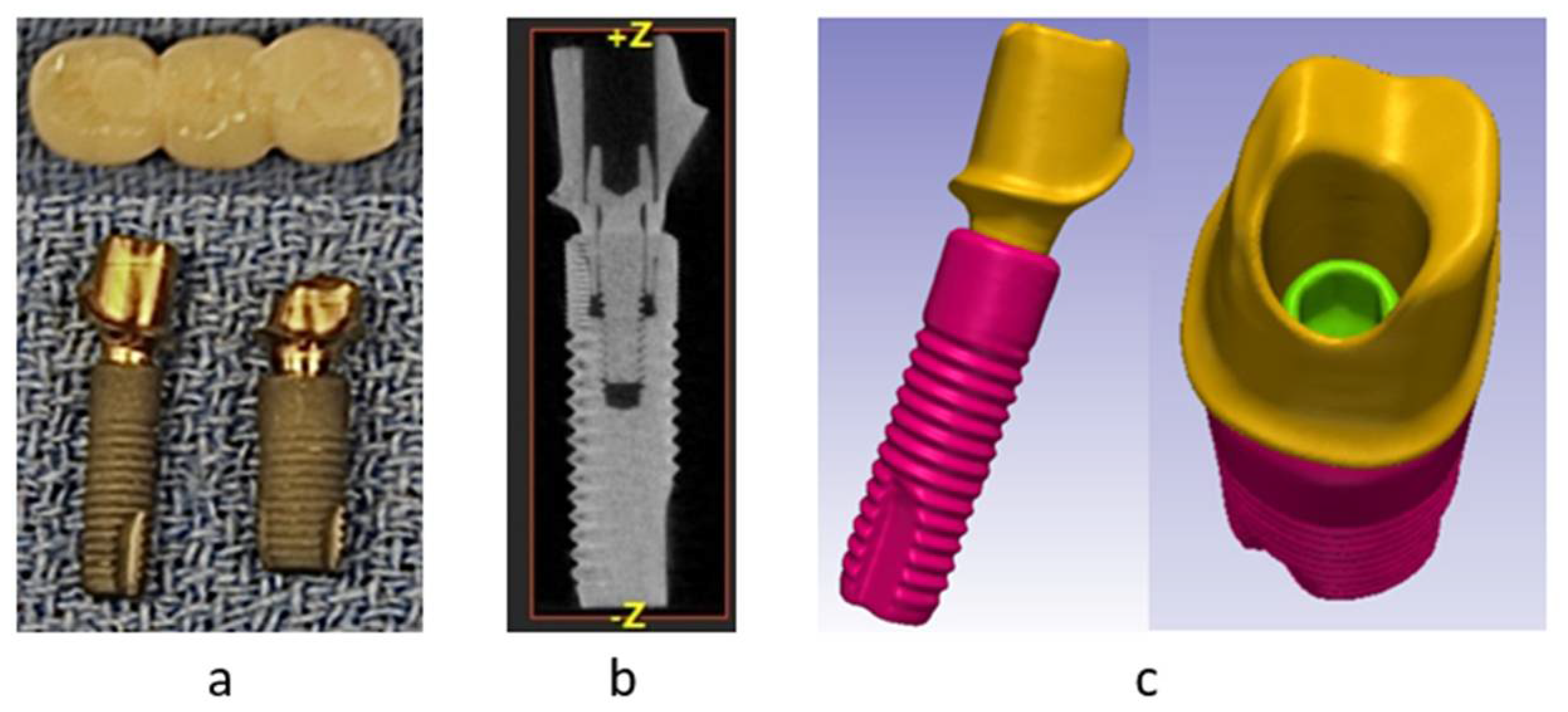
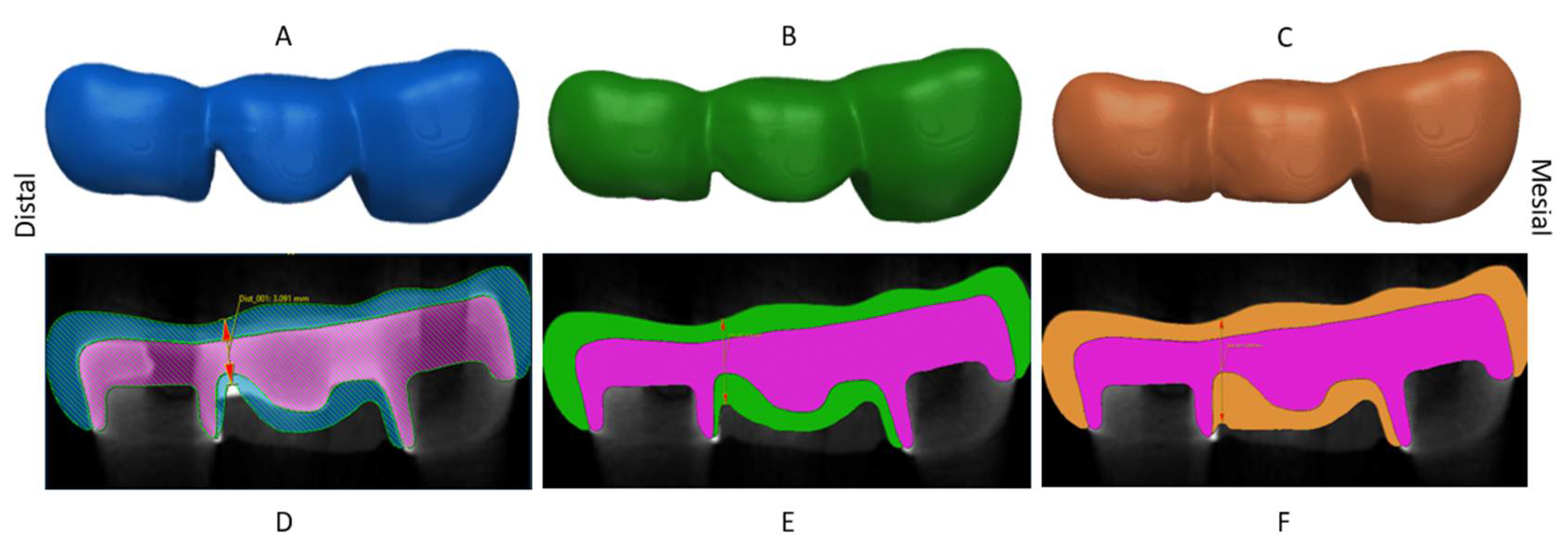
2.1. Geometry Acquisition
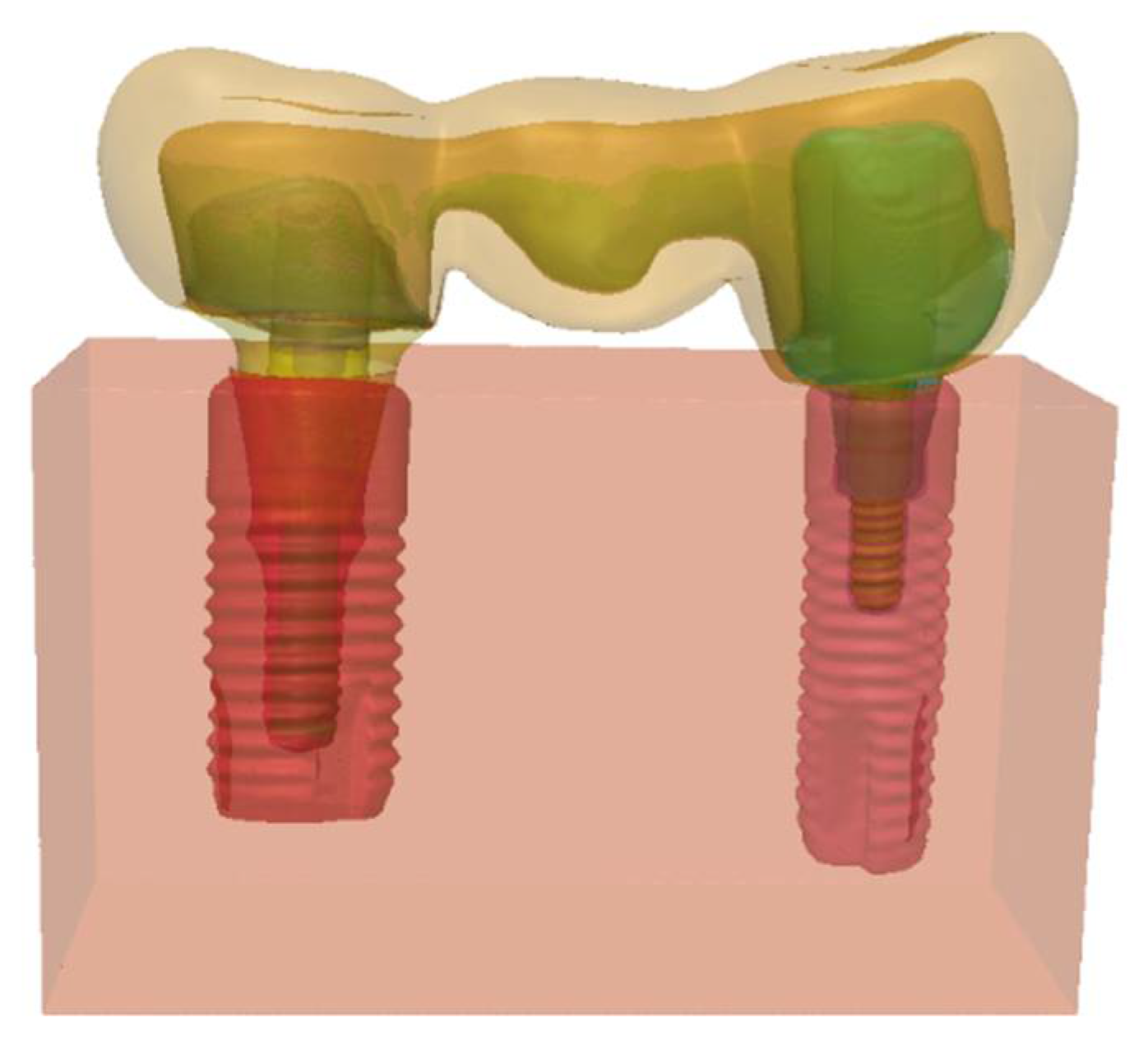
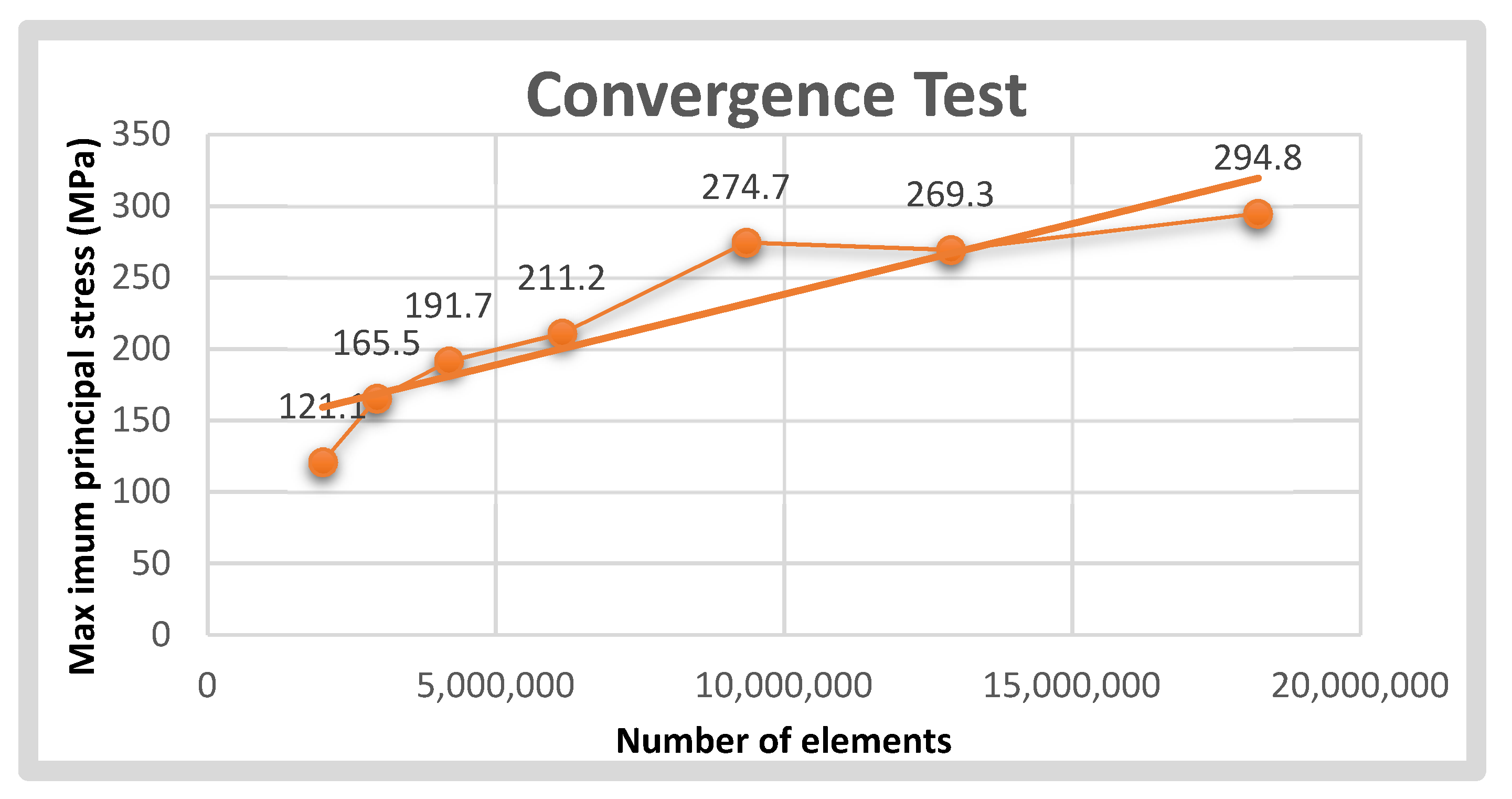
2.2. Pre-Processing
2.3. Post-Processing
3. Results
4. Discussion
5. Conclusions
Author Contributions
Funding
Institutional Review Board Statement
Informed Consent Statement
Data Availability Statement
Acknowledgments
Conflicts of Interest
References
- Denry, I.; Kelly, J.R. Emerging Ceramic-based Materials for Dentistry. J. Dent. Res. 2014, 93, 1235–1242. [Google Scholar] [CrossRef] [PubMed] [Green Version]
- Holand, W.; Schweiger, M.; Frank, M.; Rheinberger, V. A comparison of the microstructure and properties of the IPS Empress 2 and the IPS Empress glass-ceramics. J. Biomed. Mater. Res. 2000, 53, 297–303. [Google Scholar] [CrossRef]
- Jones, D.W. Development of dental ceramics. An historical perspective. Dent. Clin. N. Am. 1985, 29, 621–644. [Google Scholar] [CrossRef]
- Kelly, J.R.; Benetti, P. Ceramic materials in dentistry: Historical evolution and current practice. Aust. Dent. J. 2011, 56, 84–96. [Google Scholar] [CrossRef]
- McLaren, E.A.; White, S.N. Glass-infiltrated zirconia/alumina-based ceramic for crowns and fixed partial dentures. Pract. Periodontics Aesthet Dent 1999, 11, 985–994. [Google Scholar]
- Arena, A.; Prete, F.; Rambaldi, E.; Bignozzi, M.C.; Monaco, C.; Di Fiore, A.; Chevalier, J. Nanostructured Zirconia-Based Ceramics and Composites in Dentistry: A State-of-the-Art Review. Nanomaterials 2019, 9, 1393. [Google Scholar] [CrossRef] [Green Version]
- de Jager, N.; Münker, T.J.; Guilardi, L.F.; Jansen, V.J.; Sportel, Y.G.; Kleverlaan, C.J. The relation between impact strength and flexural strength of dental materials. J. Mech. Behav. Biomed. Mater. 2021, 122, 104658. [Google Scholar] [CrossRef]
- Callister, W.D.; Rethwisch, D.G. Materials Science and Engineering: An Introduction; Wiley: New York, NY, USA, 2010. [Google Scholar]
- Triwatana, P.; Nagaviroj, N.; Tulapornchai, C. Clinical performance and failures of zirconia-based fixed partial dentures: A review literature. J. Adv. Prosthodont. 2012, 4, 76–83. [Google Scholar] [CrossRef] [Green Version]
- Pjetursson, B.E.; Sailer, I.; Makarov, N.A.; Zwahlen, M.; Thoma, D.S. All-ceramic or metal-ceramic tooth-supported fixed dental prostheses (FDPs)? A systematic review of the survival and complication rates. Part II: Multiple-unit FDPs. Dent. Mater. 2015, 31, 624–639. [Google Scholar] [CrossRef] [Green Version]
- Sailer, I.; Balmer, M.; Hüsler, J.; Hämmerle, C.H.F.; Känel, S.; Thoma, D.S. 10-year randomized trial (RCT) of zirconia-ceramic and metal-ceramic fixed dental prostheses. J. Dent. 2018, 76, 32–39. [Google Scholar] [CrossRef] [Green Version]
- Seghi, R.R.; Denry, I.L.; Rosenstiel, S.F. Relative fracture toughness and hardness of new dental ceramics. J. Prosthet. Dent. 1995, 74, 145–150. [Google Scholar] [CrossRef]
- Zembic, A.; Sailer, I.; Jung, R.E.; Hämmerle, C.H.F. Randomized-controlled clinical trial of customized zirconia and titanium implant abutments for single-tooth implants in canine and posterior regions: 3-year results. Clin. Oral Implant. Res. 2009, 20, 802–808. [Google Scholar] [CrossRef] [PubMed] [Green Version]
- Kelly, J.R.; Tesk, J.A.; Sorensen, J.A. Failure of all-ceramic fixed partial dentures In Vitro and In Vivo: Analysis and modeling. J. Dent. Res. 1995, 74, 1253–1258. [Google Scholar] [CrossRef] [PubMed]
- Lang, L.A.; Wang, R.-F.; Kang, B.; White, S.N. Validation of finite element analysis in dental ceramics research. J. Prosthet. Dent. 2001, 86, 650–654. [Google Scholar] [CrossRef]
- White, S.; Miklus, V.; McLaren, E.; Lang, L.; Caputo, A. Flexural strength of a layered zirconia and porcelain dental all-ceramic system. J. Prosthet. Dent. 2005, 94, 125–131. [Google Scholar] [CrossRef]
- Beuer, F.; Schweiger, J.; Eichberger, M.; Kappert, H.F.; Gernet, W.; Edelhoff, D. High-strength CAD/CAM-fabricated veneering material sintered to zirconia copings—A new fabrication mode for all-ceramic restorations. Dent. Mater. 2009, 25, 121–128. [Google Scholar] [CrossRef]
- Schmitter, M.; Schweiger, M.; Mueller, D.; Rues, S. Effect on In Vitro fracture resistance of the technique used to attach lithium disilicate ceramic veneer to zirconia frameworks. Dent. Mater. 2014, 30, 122–130. [Google Scholar] [CrossRef]
- Della Bona, A.; Pecho, O.E.; Alessandretti, R. Zirconia as a Dental Biomaterial. Materials 2015, 8, 4978–4991. [Google Scholar] [CrossRef] [Green Version]
- Al-Amleh, B.; Lyons, K.; Swain, M. Clinical trials in zirconia: A systematic review. J. Oral Rehabil. 2010, 37, 641–652. [Google Scholar] [CrossRef]
- Arinc, H. Effects of Prosthetic Material and Framework Design on Stress Distribution in Dental Implants and Peripheral Bone: A Three-Dimensional Finite Element Analysis. Med. Sci. Monit. 2018, 24, 4279–4287. [Google Scholar] [CrossRef]
- Pjetursson, B.E.; Heimisdottir, K. Dental implants—Are they better than natural teeth? Eur. J. Oral Sci. 2018, 126, 81–87. [Google Scholar] [CrossRef] [PubMed]
- Sailer, I.; Strasding, M.; Valente, N.A.; Zwahlen, M.; Liu, S.; Pjetursson, B.E. A systematic review of the survival and complication rates of zirconia-ceramic and metal-ceramic multiple-unit fixed dental prostheses. Clin. Oral Implant. Res. 2018, 29, 184–198. [Google Scholar] [CrossRef] [PubMed] [Green Version]
- Alkharrat, A.R.; Schmitter, M.; Rues, S.; Rammelsberg, P. Fracture behavior of all-ceramic, implant-supported, and tooth–implant-supported fixed dental prostheses. Clin. Oral Investig. 2017, 22, 1663–1673. [Google Scholar] [CrossRef] [PubMed]
- Inan, O.; Seçilmiş, A.; Eraslan, O. Effect of pontic framework design on the fracture resistance of implant-supported all-ceramic fixed partial dentures. J. Appl. Oral Sci. 2009, 17, 533–538. [Google Scholar] [CrossRef] [PubMed]
- Ambré, M.J.; Aschan, F.; von Steyern, P.V. Fracture Strength of Yttria-Stabilized Zirconium-Dioxide (Y-TZP) Fixed Dental Prostheses (FDPs) with Different Abutment Core Thicknesses and Connector Dimensions. J. Prosthodont. 2013, 22, 377–382. [Google Scholar] [CrossRef] [PubMed]
- Kamposiora, P.; Papavasiliou, G.; Bayne, S.C.; Felton, D.A. Stress concentration in all-ceramic posterior fixed partial dentures. Quintessence Int. 1996, 27, 701–706. [Google Scholar] [PubMed]
- Kou, W.; Kou, S.; Liu, H.; Sjögren, G. Numerical modeling of the fracture process in a three-unit all-ceramic fixed partial denture. Dent. Mater. 2007, 23, 1042–1049. [Google Scholar] [CrossRef]
- Oh, W.-S.; Anusavice, K.J. Effect of connector design on the fracture resistance of all-ceramic fixed partial dentures. J. Prosthet. Dent. 2002, 87, 536–542. [Google Scholar] [CrossRef]
- Plengsombut, K.; Brewer, J.D.; Monaco, E.A.; Davis, E.L. Effect of two connector designs on the fracture resistance of all-ceramic core materials for fixed dental prostheses. J. Prosthet. Dent. 2009, 101, 166–173. [Google Scholar] [CrossRef]
- Sundh, A.; Molin, M.; Sjögren, G. Fracture resistance of yttrium oxide partially-stabilized zirconia all-ceramic bridges after veneering and mechanical fatigue testing. Dent. Mater. 2005, 21, 476–482. [Google Scholar] [CrossRef]
- Özcan, M.; Jonasch, M. Effect of Cyclic Fatigue Tests on Aging and Their Translational Implications for Survival of All-Ceramic Tooth-Borne Single Crowns and Fixed Dental Prostheses. J. Prosthodont. 2016, 27, 364–375. [Google Scholar] [CrossRef] [PubMed]
- Cervino, G.; Fiorillo, L.; Arzukanyan, A.V.; Spagnuolo, G.; Campagna, P.; Cicciù, M. Application of bioengineering devices for stress evaluation in dentistry: The last 10 years FEM parametric analysis of outcomes and current trends. Minerva Stomatol. 2020, 69, 55–62. [Google Scholar] [CrossRef] [PubMed]
- Meira, J.; Jikihara, A.N.; Capetillo, P.; Roscoe, M.; Cattaneo, P.M.; Ballester, R.Y. Finite element analysis in dentistry. Dent. Biomater. World Sci. Ser. Biomater. Towards Med. Dev. 2018, 2, 67–89. [Google Scholar]
- Gowda, S.; Quadras, D.D.; Sesappa, R.S.; Katapadi, V. Evaluation of Effect of Connector Designs in Implant Tooth-supported Fixed Partial Denture: A Two-dimensional Finite Element Analysis. J. Contemp. Dent. Pract. 2018, 19, 669–674. [Google Scholar] [CrossRef] [PubMed]
- Correia, A.; Fernandes, J.C.; Campos, J.C.; Vaz, M.; Ramos, N.; da Silva, J.M. Effect of connector design on the stress distribution of a cantilever fixed partial denture. J. Indian Prosthodont. Soc. 2009, 9, 13. [Google Scholar] [CrossRef]
- Eraslan, O.; Sevimay, M.; Usumez, A.; Eskitascioglu, G. Effects of cantilever design and material on stress distribution in fixed partial dentures—A finite element analysis. J. Oral Rehabil. 2005, 32, 273–278. [Google Scholar] [CrossRef]
- Kou, W.; Li, D.; Qiao, J.; Chen, L.; Ding, Y.; Sjögren, G. A 3D numerical simulation of stress distribution and fracture process in a zirconia-based FPD framework. J. Biomed. Mater. Res. Part B Appl. Biomater. 2011, 96B, 376–385. [Google Scholar] [CrossRef] [Green Version]
- Lakshmi, R.; Abraham, A.C.; Sekar, V.; Hariharan, A. Influence of connector dimensions on the stress distribution of monolithic zirconia and lithium-di-silicate inlay retained fixed dental prostheses—A 3D finite element analysis. Tanta Dent. J. 2015, 12, 56–64. [Google Scholar] [CrossRef] [Green Version]
- Thompson, M.; Field, C.; Swain, M. The all-ceramic, inlay supported fixed partial denture. Part 2. Fixed partial denture design: A finite element analysis. Aust. Dent. J. 2011, 56, 302–311. [Google Scholar] [CrossRef]
- Alberto, L.H.J.; Kalluri, L.; Esquivel-Upshaw, J.F.; Duan, Y. Three-Dimensional Finite Element Analysis of Different Connector Designs for All-Ceramic Implant-Supported Fixed Dental Prostheses. Ceramics 2022, 5, 34–43. [Google Scholar] [CrossRef]
- Kalluri, L.; Seale, B.; Satpathy, M.; Esquivel-Upshaw, J.; Duan, Y. Three-Dimensional Finite Element Analysis of the Veneer—Framework Thickness in an All-Ceramic Implant Supported Fixed Partial Denture. Ceramics 2021, 4, 199–207. [Google Scholar] [CrossRef]
- Esquivel-Upshaw, J.F.; Clark, A.E.; Shuster, J.J.; Anusavice, K.J. Randomized Clinical Trial of Implant-Supported Ceramic-Ceramic and Metal-Ceramic Fixed Dental Prostheses: Preliminary Results. J. Prosthodont. 2013, 23, 73–82. [Google Scholar] [CrossRef] [PubMed]
- Esquivel-Upshaw, J.; Mecholsky, J.; Clark, A.; Jenkins, R.; Hsu, S.; Neal, D.; Ren, F. Factors influencing the survival of implant-supported ceramic-ceramic prostheses: A randomized, controlled clinical trial. J. Dent. 2020, 103, 100017. [Google Scholar] [CrossRef] [PubMed]
- Wittek, A.; Miller, K. Computational biomechanics for medical image analysis. In Handbook of Medical Image Computing and Computer Assisted Intervention; Academic Press: Cambridge, MA, USA, 2019; pp. 953–977. [Google Scholar] [CrossRef]
- Fathy, S.M. Three-Dimensional Finite Element Analysis of Lower Molar Tooth Restored with Fully Milled and Layered Zirconia Crowns. J. Dent. Health Oral Disord. Ther. 2014, 1, 89–95. [Google Scholar] [CrossRef] [Green Version]
- Bataineh, K.; Al Janaideh, M.; Abu-Naba’A, L.A. Fatigue Resistance of 3-Unit CAD-CAM Ceramic Fixed Partial Dentures: An FEA Study. J. Prosthodont. 2022, 1–9, online ahead of print. [Google Scholar] [CrossRef] [PubMed]
- Fischer, H.; Weber, M.; Marx, R. Lifetime Prediction of All-ceramic Bridges by Computational Methods. J. Dent. Res. 2003, 82, 238–242. [Google Scholar] [CrossRef]
- Schmid, A.; Strasser, T.; Rosentritt, M. Finite element analysis of occlusal interferences in dental prosthetics caused by occlusal adjustment. Int. J. Prosthodont. 2021. [Google Scholar] [CrossRef]
- Yu, W.Q.; Li, X.Q.; Chen, S.Y.; Ma, X.N.; Xu, X. Three-dimensional finite element analysis of different framework materials in implant-supported fixed mandibular prosthesis. Zhonghua Kou Qiang Yi Xue Za Zhi Zhonghua Kouqiang Yixue Zazhi Chin. J. Stomatol. 2021, 56, 190–195. [Google Scholar]
- Von Steyern, P.V.; Kokubo, Y.; Nilner, K. Use of abutment-teeth vs. dental implants to support all-ceramic fixed partial dentures: An In-Vitro study on fracture strength. Swed. Dent. J. 2005, 29, 53–60. [Google Scholar]
- Bahat, Z.; Mahmood, D.J.H.; Von Steyern, P.V. Fracture strength of three-unit fixed partial denture cores (Y-TZP) with different connector dimension and design. Swed. Dent. J. 2009, 33, 149–159. [Google Scholar]
- Larsson, C.; Holm, L.; Lövgren, N.; Kokubo, Y.; VON Steyern, P.V. Fracture strength of four-unit Y-TZP FPD cores designed with varying connector diameter. An In-Vitro study. J. Oral Rehabil. 2007, 34, 702–709. [Google Scholar] [CrossRef] [PubMed]
- Esquivel-Upshaw, J.F.; Mehler, A.; Clark, A.E.; Neal, D.; Anusavice, K.J. Fracture analysis of randomized implant-supported fixed dental prostheses. J. Dent. 2014, 42, 1335–1342. [Google Scholar] [CrossRef] [PubMed] [Green Version]
- Pjetursson, B.E.; Brägger, U.; Lang, N.P.; Zwahlen, M. Comparison of survival and complication rates of tooth-supported fixed dental prostheses (FDPs) and implant-supported FDPs and single crowns (SCs). Clin. Oral Implant. Res. 2007, 18, 97–113. [Google Scholar] [CrossRef] [PubMed]
- Heintze, S.D.; Rousson, V. Survival of zirconia- and metal-supported fixed dental prostheses: A systematic review. Int. J. Prosthodont. 2010, 23, 493–502. [Google Scholar]
- Sallenave, R.F.; Vicari, C.B.; Borba, M. Ceramic abutments for implant-supported restorations: Literature review. Cerâmica 2016, 62, 305–308. [Google Scholar] [CrossRef]


| Materials | Model Components | Young’s Modulus (MPa) | Poisson’s Ratio |
|---|---|---|---|
| Porcelain | Veneer | 70,000 | 0.19 |
| Zirconia | Framework Abutments | 210,000 | 0.30 |
| Resin cement | Fillings Cement layer | 8300 | 0.30 |
| Titanium | Implants Screws | 110,000 | 0.35 |
| Bone | Cuboid (bone) | 13,700 | 0.30 |
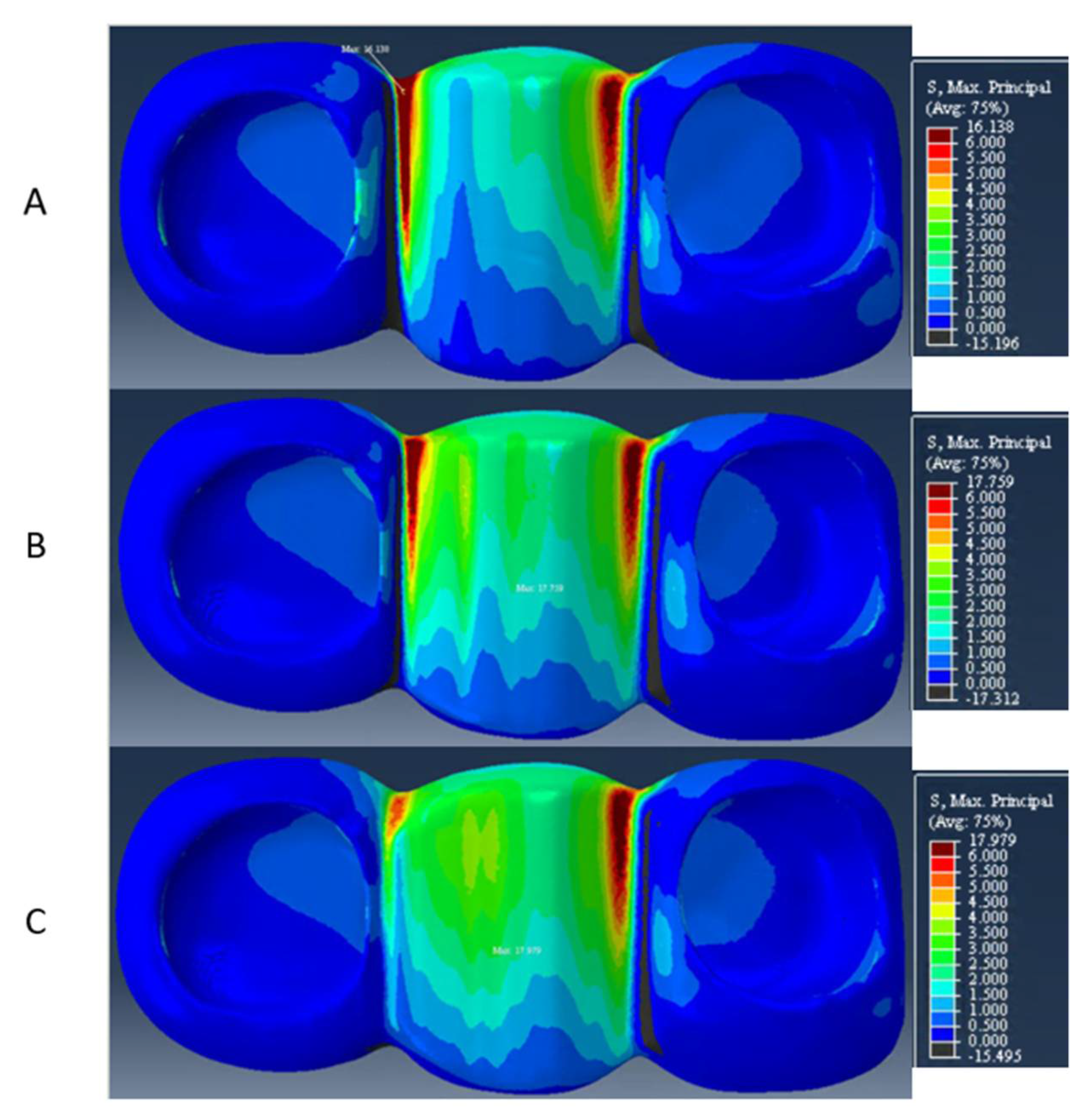
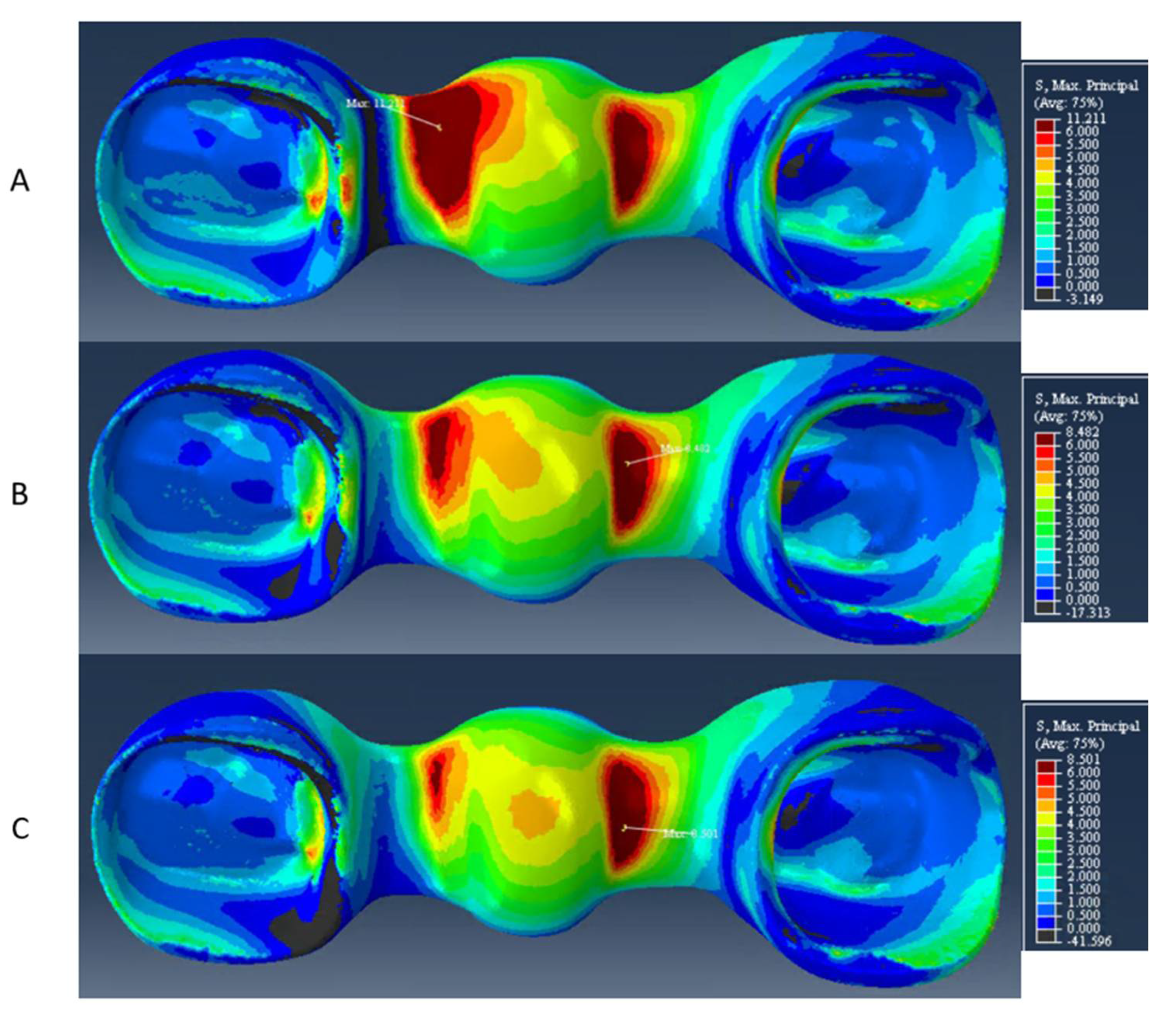
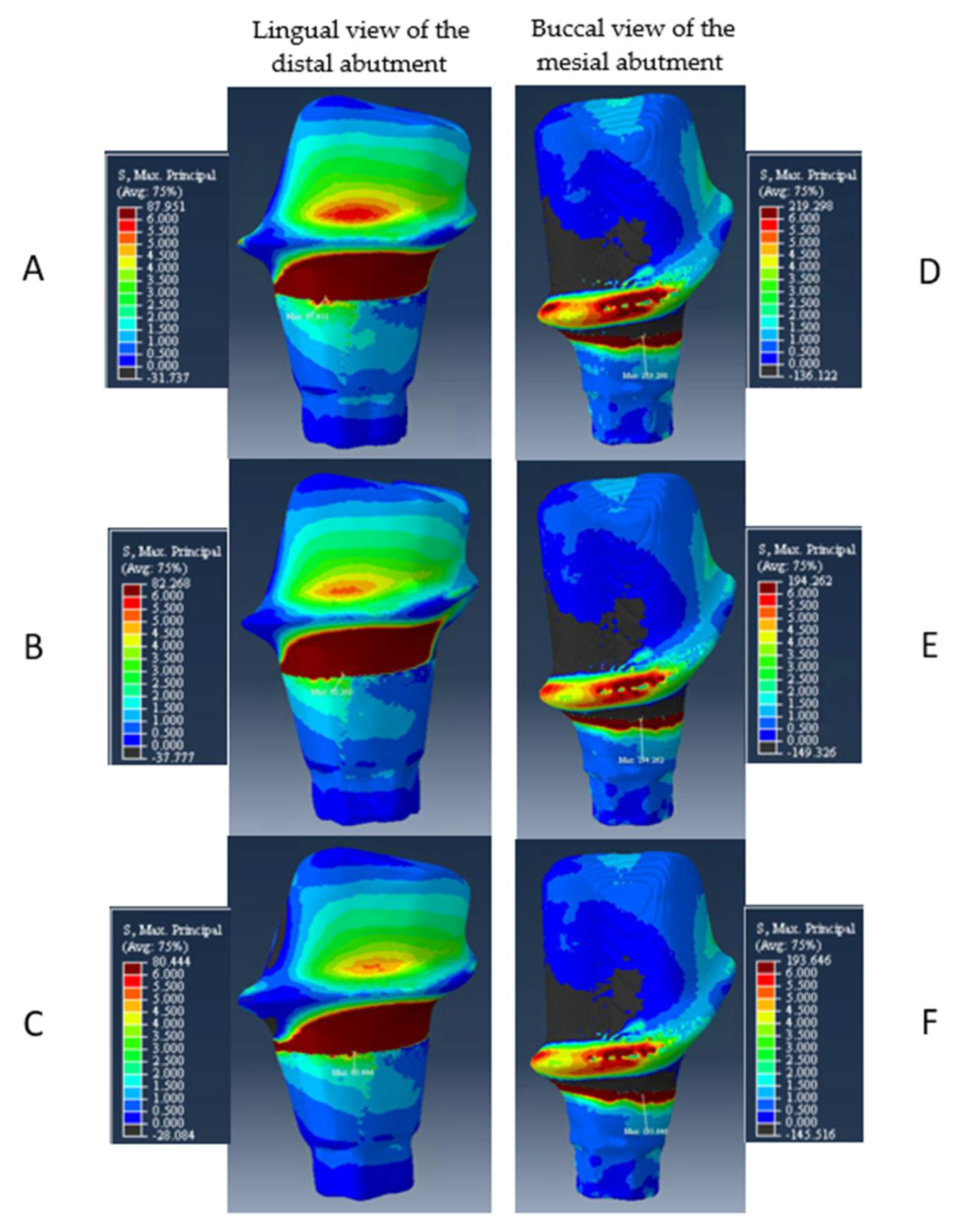
| Models | Distal Connector Height | Veneer | Veneer (Gingival Aspect) | Framework | Mesial Abutment | Distal Abutment |
|---|---|---|---|---|---|---|
| A | 3 mm | 16 MPa | 16 MPa | 11 MPa | 219 MPa | 88 MPa |
| B | 4 mm | 18 MPa | 10 MPa | 8 MPa | 194 MPa | 82 MPa |
| C | 5 mm | 18 MPa | 8 MPa | 8 MPa | 194 MPa | 80 MPa |
Publisher’s Note: MDPI stays neutral with regard to jurisdictional claims in published maps and institutional affiliations. |
© 2022 by the authors. Licensee MDPI, Basel, Switzerland. This article is an open access article distributed under the terms and conditions of the Creative Commons Attribution (CC BY) license (https://creativecommons.org/licenses/by/4.0/).
Share and Cite
Alberto, L.H.J.; Kalluri, L.; Esquivel-Upshaw, J.F.; Duan, Y. Finite Element Analysis of an Implant-Supported FDP with Different Connector Heights. Symmetry 2022, 14, 2334. https://doi.org/10.3390/sym14112334
Alberto LHJ, Kalluri L, Esquivel-Upshaw JF, Duan Y. Finite Element Analysis of an Implant-Supported FDP with Different Connector Heights. Symmetry. 2022; 14(11):2334. https://doi.org/10.3390/sym14112334
Chicago/Turabian StyleAlberto, Laura H. J., Lohitha Kalluri, Josephine F. Esquivel-Upshaw, and Yuanyuan Duan. 2022. "Finite Element Analysis of an Implant-Supported FDP with Different Connector Heights" Symmetry 14, no. 11: 2334. https://doi.org/10.3390/sym14112334