Article

User Selection Approach in Multiantenna Beamforming NOMA Video Communication Systems

1
Department of Electronic Engineering, National Taipei University of Technology, Taipei 106, Taiwan
2
Bowers & Wilkins, Taipei 104, Taiwan
*
Author to whom correspondence should be addressed.
Symmetry 2021, 13(9), 1737; https://doi.org/10.3390/sym13091737
Submission received: 9 August 2021 / Revised: 9 September 2021 / Accepted: 16 September 2021 / Published: 18 September 2021

Abstract

:
For symmetric non-orthogonal multiple access (NOMA)/multiple-input multiple-output (MIMO) systems, radio resource allocation is an important research problem. The optimal solution is of high computational complexity. Thus, one existing solution Kim et al. proposed is a suboptimal user selection and optimal power assignment for total data rate maximization. Another existing solution Tseng et al. proposed is different suboptimal user grouping and optimal power assignment for sum video distortion minimization. However, the performance of sub-optimal schemes by Kim et al. and Tseng et al. is still much lower than the optimal user grouping scheme. To approach the optimal scheme and outperform the existing sub-optimal schemes, a deep neural network (DNN) based approach, using the results from the optimal user selection (exhaustive search) as the training data, and a loss function modification specific for NOMA user selection to meet the constraint that a user cannot be in both the strong and weak set, and avoid the post processing online computational complexity, are proposed. The simulation results show that the theoretical peak signal-to-noise ratio (PSNR) of the proposed scheme is higher than the state-of-the-art suboptimal schemes Kim et al. and Tseng et al. by 0.7~2.3 dB and is only 0.4 dB less than the optimal scheme at lower online computational complexity. The online computational complexity (testing stage) of the proposed DNN user selection scheme is 60 times less than the optimal user selection scheme. The proposed DNN-based scheme outperforms the existing suboptimal solution, and slightly underperforms the optimal scheme (exhaustive search) at a much lower computation complexity.

1. Introduction

To meet the rapidly increasing consumer demand for wireless data, especially wireless video delivery, wireless transmission technology is continuously evolving. To efficiently manage the resources of the wireless transmission technology, resource allocation such as user selection and beamforming group allocation is key. The multiple-input multiple-output (MIMO) has been used in wireless communications. Chen et al. [1] investigated resource management in MIMO systems for multiview 3D video delivery. Yang et al. [2] proposed user grouping for multicell uplink multiuser MIMO systems to achieve higher sum rates. Lee et al. [3] proposed a cross-layer optimization scheme for heterogeneous multiuser MIMO networks.
In addition, non-orthogonal multiple access (NOMA) can meet the world’s demand for higher data transmission rate. NOMA has promising applications in 5G networks and beyond [4,5,6,7] and the digital TV standard ATSC 3.0 [8]. NOMA can serve more than one user at the same radio resource, and has higher bandwidth efficiency than conventional orthogonal multiple access (OMA) [9]. Since the receiver uses serial interference cancellation (SIC) technology, multiple signals can be combined and transmitted [10].
Combining MIMO and NOMA can achieve higher spectrum efficiency and diversity. Senel et al. [11] shown that the combination of multi-user beamforming and NOMA outperforms two standalone schemes. Uplink NOMA-MIMO systems include [12,13,14]. Kim et al. [12] proposed a user grouping considering the correlation between strong and weak users and proposed a power control scheme to maximize the sum rate in NOMA–MIMO systems. Tseng et al. [13] proposed an improved weak user selection scheme in the physical layer, and a power allocation/user substitution scheme in the application layer. This is a cross-layer approach just as with non-NOMA systems [15,16]. Qureshi et al. [14] proposed a concept of successive bandwidth division (SBD). The above conventional schemes are usually iterative and thus have high computational complexity. This high complexity is called algorithm deficit and motivates the application of the deep learning [17]. The deep learning-based approach has inherent parallel processing structure which can accelerate at the graphic processing unit (GPU), but the conventional scheme is usually a sequential operation and doesn’t have parallel processing structure for accelerating by the GPU. Therefore, the computational complexity of the deep-learning-based scheme is much less than that of the non-deep-learning-based scheme in terms of execution time in a platform with a GPU [18,19,20].
In addition, deep learning is widely used in pattern recognition, speech recognition, signal processing [21,22], communications, and networks [4,18,23,24]. Kim et al. [21] proposed deep learning for antenna design and radar signal processing. To learn the suboptimal scheme (weighted minimum mean square error, WMMSE), Sun et al. [22] applied deep learning and achieved the performance close to the iterative suboptimal WMMSE algorithm. Gui et al. [4] investigated an auto-encoder approach of a NOMA system. Kim et al. [18] investigated deep learning for sparse code multiple access (SCMA) López et al. [23] proposed deep learning to increase the probability of success in forecasting primary users in cognitive radio networks. Wang et al. [24] surveyed the most recent spectrum allocation schemes by reinforcement learning in cognitive radio networks.
Due to the algorithm deficit, deep learning is applicable for communications and yields lower-complexity solutions. At the testing stage (the runtime) of the deep neural network (DNN), the deep learning-based approach is expected to have much smaller computational complexity than that of non-deep learning approaches, such as 11.34 times lower for a small 6 × 4 SCMA system on a desktop computer with GPU NVIDIA 1080Ti [18], 100 times faster in power control of underlaid device-to-device communications [19], and 28.72 times less execution time for OFDMA-massive MIMO resource allocation [20].
In summary, the combination of NOMA and MIMO provides higher data rates to meet the increasing demand of wireless video. The addition of deep learning can significantly reduce the online computational complexity.

2. Related Works

For NOMA-MIMO systems, user selection is a key research topic. One prior work [12] proposed a suboptimal user selection and optimal power allocation to maximize sum data rate. Another prior work [13] proposed different suboptimal user selection and optimal power allocation to minimize the sum video mean square error (MSE) distortion. The comparison of the prior works and the proposed scheme is made in Table 1.
Deep learning has been applied for radio resource allocation in wireless communication systems. Sun et al. [22] proposed learning from the suboptimal WMMSE algorithm and achieved a performance close to the suboptimal WMMSE algorithm. Lee et al. [19] proposed power control of underlaid device-to-device communications. Tseng et al. [25] proposed learning resource allocation scheme for OFDMA/NOMA systems from a suboptimal scheme. A post processing scheme for the testing stage is also proposed to guarantee the constraint that each user has at least one subcarrier for user fairness. Wang [26] proposed a modified loss function in the training processing of OFDMA-NOMA resource allocation such that the constraint that each user has at least one subcarrier is usually satisfied.
The performance of the suboptimal schemes by Kim et al. [12] and Tseng et al. [13] still shows a significant gap with the optimal scheme. The previous works about deep learning for radio resource allocations in [22,25,26] all learn from the suboptimal scheme (training data), so their performance would be slightly worse than the suboptimal scheme and can’t be close to the optimal solution. Our proposed scheme uses the DNN to learn the strong/weak set user selection from the optimal solution (by exhaustive search) and thus performs better than the suboptimal scheme, and close to the optimal scheme at the lower complexity.
Compared to the prior works, our proposed scheme makes the following contribution:
(1)
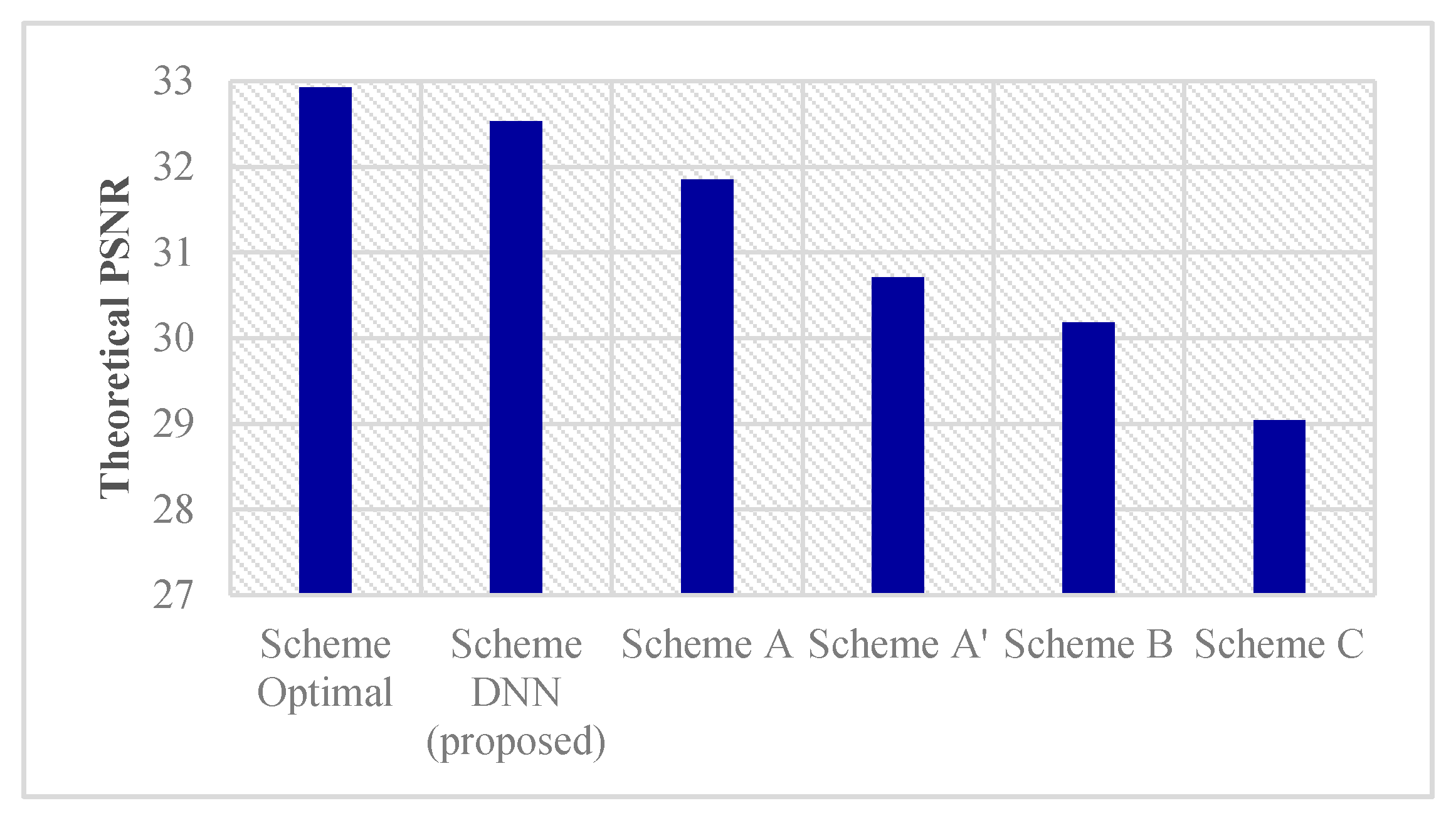
A deep learning scheme (Scheme DNN in Section 4) to learn from the optimal scheme (Scheme Optimal) is proposed. The Scheme Optimal attempts all the combinations/permutations of K candidate users (exhaustive search) and chooses the best performing user grouping. Scheme DNN uses the Scheme Optimal results as training data. The proposed Scheme DNN achieves near optimal performance at lower complexity. It outperforms the previous suboptimal schemes proposed in [12,13].
(2)
A new loss function for deep learning of the user selection to deal with constraint violation is proposed. If a user is selected in both of the strong set and weak set (constraint violation), extra value is added to the cost function. This avoids post-processing after the training stage to satisfy the constraint that a user can’t be in both of the strong set and weak set and reduces the complexity. For comparison, Tseng. et. al. [25] investigated the deep leaning-based resource allocation for OFDMA/NOMA but not MIMO. Its scheme has the post-processing after the training stage to satisfy the constraints and additional complexity and latency during the runtime. The scheme in [26] modified the loss function for satisfying the constraint that each user has at least one subcarrier and thus avoid post-processing, but it deals with different constraint (a user has at least one subcarrier, not that a user can’t be in both of the strong set and weak set) in different systems (OFDMA/NOMA, not NOMA-MIMO).
(3)
The proposed deep learning approach for NOMA resource management crosses the physical and application layers. Previous NOMA schemes such as [4,5,6,12,27] focus on the physical layer and there is currently no deep learning-based cross-layer user selection scheme for NOMA-MIMO video systems [28,29,30].
The remaining part of this paper is organized as follows. Section 3 describes the system model. Section 4 describes the proposed deep learning approach and proposed modified cost function for constrained optimization. Our simulation results are shown in Section 5. The conclusion is given in Section 6.

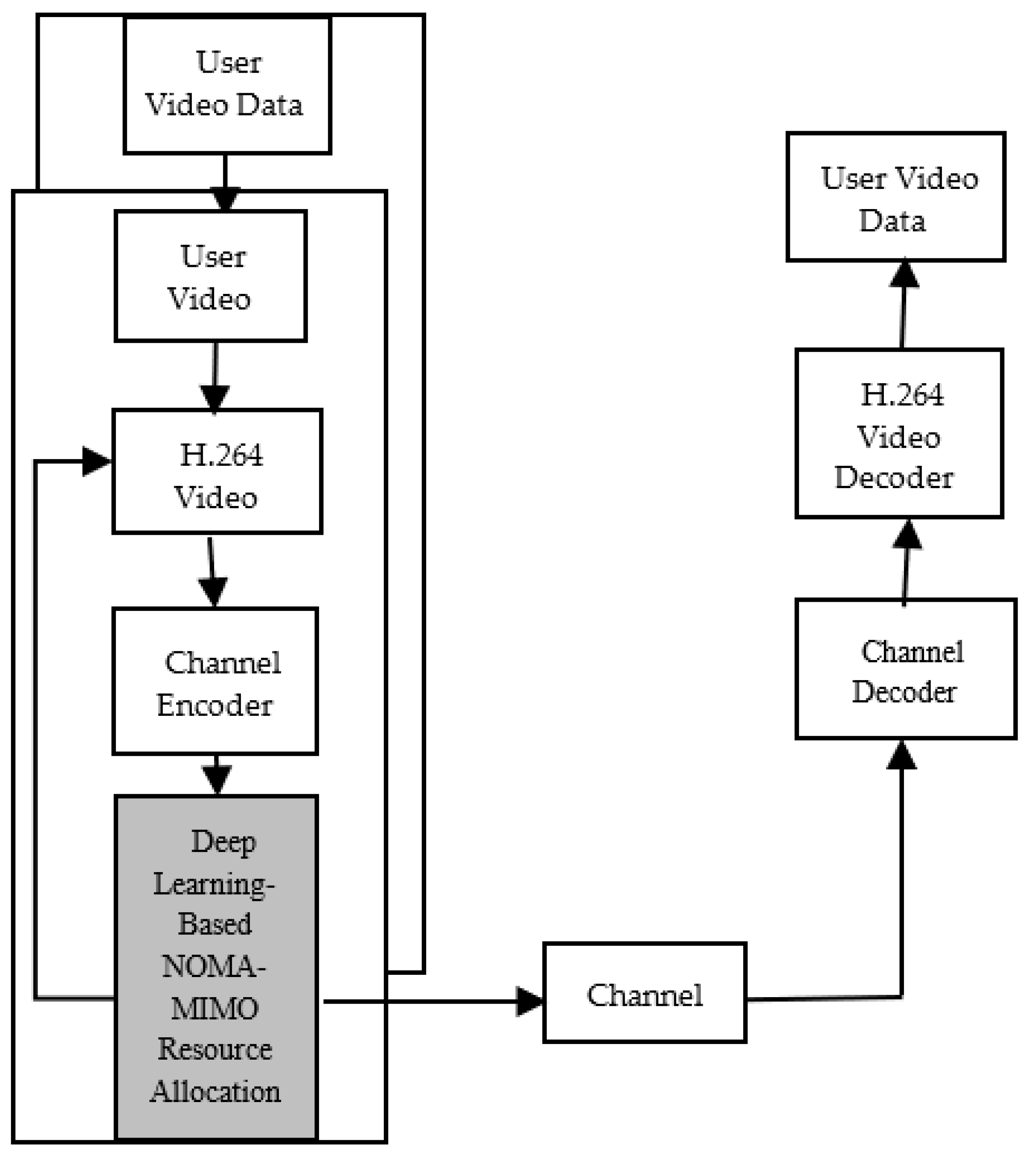
3. Uplink NOMA-MIMO Video Transmission System Model

Section 3.1, Section 3.2 and Section 3.3 describe the structure of the uplink NOMA-MIMO video communication system, received signal model, and multiantenna beamforming method ZF post-coder. Key idea is the N antennas at the BS creates N multiantenna beamforming groups and NOMA allows two users in the same resource, so total 2N users can be supported in the uplink NOMA-MIMO systems, so the sum data rates of all users are 2N times.
Section 3.4 is the received SINR and then the information (data) rate in (9) and (13) for the strong and weak NOMA users, respectively. The information (data) rate is a physical layer metric used in the prior work [12]. Section 3.5 describes the model of the video MSE distortion in (14) which is a function of the information (data) rates in Section 3.4. The video MSE distortion is a cross layer metric used in the prior work [13] and the proposed scheme. Then, the video quality indicator, PSNR, is a log expression of the video MSE distortion and defined in (17).

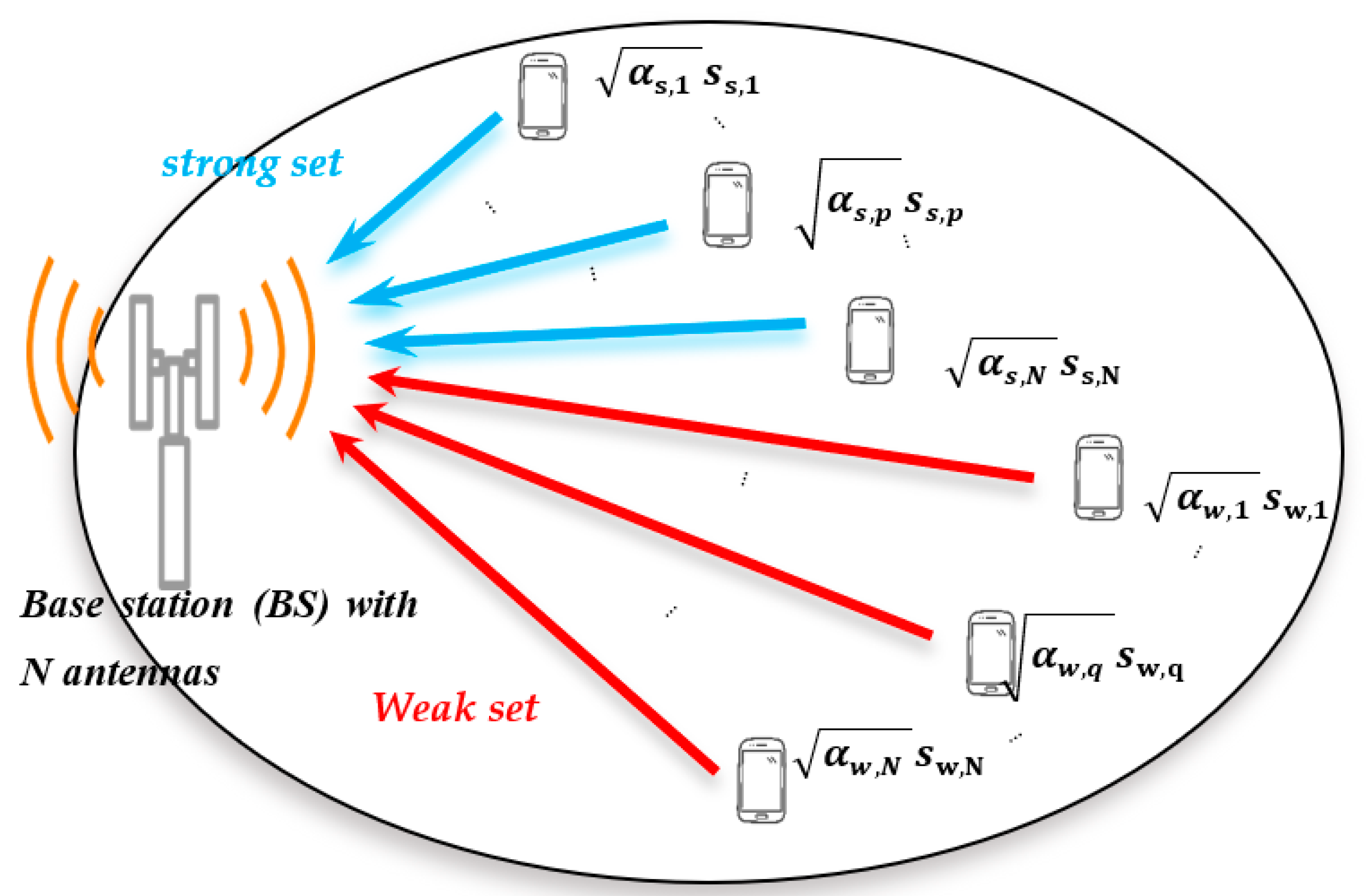
3.1. Uplink Noma-Mimo System Structure

The structure of the symmetric uplink NOMA–MIMO video transmission system is shown in Figure 1, and is the same as that in [12,13] except the gray part-resource allocation. The resource allocation in [12,13] are non-deep-learning-based. The resource allocation block in Figure 1 is a deep learning-based one with the training data obtained from the optimal solution. Figure 2 shows the symmetric uplink NOMA-MIMO system model with K users and N antennas at the BS, K < 2 N, and is the same as that in [12,13]. Overall, the uplink NOMA-MIMO video transmission system model in Figure 1 and Figure 2 is the same as that in [12,13] except that the resource allocation is based on deep-learning.

3.2. Received Signal Model

The received signal of all the groups with all users in the uplink NOMA system can be expressed as follows:
y = H s x s + H w x w + n a w g n  
where H s and H w denote the channel matrix of the strong and weak sets, respectively. n a w g n is the additive white Gaussian noise (AWGN) with power P a w g n , and x s , x w are the N × 1 transmitted signal vector of the strong and weak sets, respectively.
The channel vectors of the strong and weak sets can be denoted as
H s = [ h s , 1   h s , p h s , N ] ,   H w = [ h w , 1   h w , q h w , N ]
where p   { 1 , 2 , , N } ,   q { 1 , 2 , , N } , and h s , p , h w , q are the N   × 1 uplink channel matrix of the p-th and q-th users in the strong and weak sets, respectively.
The transmitted signal vector of the strong and weak set is given by
x s = [ α s , 1 s s , 1   α s , p s s , p α s , N s s , N ] t r
x w = [ α w , 1 s w , 1   α w , q s w , q α w , N s w , N ] t r
where ( . ) t r denotes the transpose of the matrix. s s , p and s w , q are the signal of the p-th and q-th user in the strong set and weak set, respectively. α s , p   and   α w , q are the power control factors of the p-th and q-th user in the strong set and weak set, respectively.

3.3. Multiantenna Beamforming: Zero-Forcing Post-Coder

As in [12], the BS in an uplink (UL) beamforming NOMA system can utilize the CSI of the entire set of users. In order to eliminate intra-set interference, the zero-forcing (ZF) scheme to generate the post-coding matrix is used. Based on H s and H w , W s and W w are defined to be the ZF post-coding matrices
W s = [ w s , 1 t r w s , j t r w s , N t r ] t r = ( H s ) * ( ( H s ) ( H s ) * ) 1 W w = [ w w , 1 t r w w , j t r w w , N t r ] t r = ( H w ) * ( ( H w ) ( H w ) * ) 1
where ( . ) * is the complex conjugate of the matrix, and w s , j and w w , j is the 1 × N ZF post-coder of the j-th user in the strong set and weak set, respectively.

3.4. Received Sinr and Information (Data) Rate of Users

As mentioned above, the strong set signal after post-coding for the strong set can be obtained using W s and the received vector, z s = [ z s , 1 z s , n z s , N ] t r is achieved as follows
  z s = W s y = W s H s x s + W s H w x w + W s n a w g n
The received signal of strong set user (s, p) is expressed as
z s , p = | h s , p | α s , p s s , p + ( Σ q = 1 N w s , p h w , q α w , q s w , q ) + w s , p n a w g n
where ( Σ q = 1 N w s , p h w , q α w , q s w , q ) represents the interference coming from the weak user. The received SINR of the strong user ( s , p ) is denoted as follows:
S I N R s , p = | h s , p | 2 α s , p P s , p q = 1 N | w s , p h w , q | 2 α w , q P w , q + P a w g n  
Then w the information rate of the strong set user ( s , p ) is given by
r a t e s , p ( α s , p ) = BW l o g 2 ( 1 + η P s , p α s , p | h s , p | 2 P a w g n + q = 1 N | w s , p h w , q | 2 α w , q P w , q ) = BW l o g 2 ( 1 + α s , p A s , p 1 + α w , q C p ) ,
where BW is the signal bandwidth, A s , p = η P s , p | h s , p | 2 P a w g n ,   C p = q = 1 N P w , q | w s , p h w , q | 2 / P a w g n     and   η represents the gap to the theoretical capacity [13,15].
The transmit power of strong user (s, p) and weak user (w, q) is denoted as P s , p and   P w , q , respectively. The maximum transmit power per user is P m a x , and p N is the power of the noise. On the opposite side, the weak set signal can be decoded by perfect SIC after the signal interference from the strong set is removed. Then z w = [ z w , 1 z w , q z w , N ] t r after the W w ZF post-coder is achieved, and the received vector of the weak set is represented as
z w = W w H w x w + W w n a w g n
z w , q = | h w , q | α w , q s w , q + w w , q n a w g n
The received SINR of the weak user
S I N R w , q = | h w , q | 2 α w , q P w , q P a w g n  
Then the information rate of the weak user
r a t e w , q ( α w , q ) = BW l o g 2 ( 1 + η P w , q α w , q | h w , q | 2 P a w g n   ) = BW l o g 2 ( 1 + α w , q A w , q ) ,
where A w , q = η P W , q | h w , q | 2 P a w g n

3.5. Video MSE Distortion Model and Psnr

According to the video distortion model [15], the video MSE of each group of pictures (GOP) of the NOMA system can be approximated as the following equation [31]:
MSE N O M A = a k + b k rate N O M A + c k
The   rate N O M A is either   rate s , p in (9) for strong users or rate w , q in (13) for weak users. The a k ,   b k , and c k are fitted before transmission and depend on the video content [15,16,25].
The video MSE of the OMA system is
MSE O M A = a k + b k rate O M A + c k
The information rate of the OMA system is
rate O M A = BW 1 2   l o g 2 ( 1 + A O M A )
The reason that A O M A approximates to A w , q , the parameter of the weak user in NOMA system, is that the users of the OMA system do not interfere with each other, so A O M A = η P O M A , k | h O M A , k | 2 P a w g n , where P O M A , k is the transmit power of the OMA user, and h O M A , k is the channel vector of the OMA user,
The PSNR, peak signal-to-noise ratio, is defined as [31]
PSNR = 10 × log 10 255 × 255 MSE
The theoretical PSNR is obtained by using MSE in (14), (15). The simulated PSNR is obtained by using MSE in the simulation, which accounts for channel-induced errors, imperfect source encoding rate control etc. [15].

4. Proposed Deep Learning Approach for User Selection (Scheme DNN)

The optimal user grouping is to attempt all the combinations/permutations of K candidate users (exhaustive search) and choose the best performing grouping, where K is the number of candidate users that BS can choose from. Its complexity is high, so the user set selections in the previous studies such as [12,13] are heuristic suboptimal solutions. The proposed deep learning approach for user selection uses optimal user grouping results as the training data and achieves near optimal performance at lower online computational complexity.

4.1. Deep Neural Networks Structure

Figure 3 is the proposed fully-connected deep neural network (DNN) model for user selection. The output layer is separated into a strong set selection and weak set selection.
The normalized channel gains [32] (physical layer) and RD-function parameters (application layer) of all users are adoppted as the input to the DNN, and the output data is the user grouping result and can be represented as a 2 × K matrix. The first 1XK matrix indicates N users selected in the strong set (N ones, the others are zeros). The second 1XK matrix indicates N users selected in the weak set (N ones, the others are zeros). Therefore, it is possible that a user is in both strong and weak set. Furthermore, for DNN, the data needs to be one-dimensional, so the output data are reshaped to a 1 × 2 K matrix.
The training data in the form of (DNN input, DNN desired output) pair are generated as follows. The channel coefficients are the DNN input of the training data and randomly generated based on the independent and identically distributed (i.i.d.) probabilistic model. The 1 × 2K resource allocation matrix is the output of the training data and obtained from the optimal or suboptimal resource allocation algorithm such as Scheme Optimal or Scheme A [13] in the next section. The testing data are generated in a similar way. The channel coefficients are generated based on the i.i.d. probabilistic model, and different from those in the training data.

4.2. DNN System Model

ω is used to represent the parameters of the DNN, ω = { ω 1 , ω 2 ,…, ω L }. The set of the parameters of the layer l is ω l = { W l , b l }. W l is the weight of the neurons and b l is the bias of the neurons at the l-th layer. The l-th layer can be denoted as follows:
Y l = σ ( W l X l + b l )
where σ ( ) is an activation function. A rectified linear unit function (ReLU function) with σ R e L U (x) = max (0, x) is used as the activation function in each layer except for the last layer. The ReLU function can keep the gradient at 1 and the size of gradients will not reduce exponentially when back-propagating via many layers [33].
The softmax activation function in the output layer was attempted. All user combinations in the NOMA system are numbered and the pre-training data are transformed into numbers as DNN training data. The number is converted back to the original data type after training. However, the accuracy of this method is only 30%. Finally, the original training data are used and the activation function is changed to sigmoid σ s i g m o i d ( x ) = 1 1 + e x , which maps the output to interval [0, 1].
Binary cross-entropy (BCE) is used for the cost function since it is a classification problem:
L o s s 1 ( W , b ) = 1 K i K [ Y ( i ) ln ( Y L ( i ) ) + ( 1 Y ( i ) ) ln ( 1 Y L ( i ) ) ]
where Y ( i ) is the labeled (desired) DNN output and Y L ( i ) is the DNN output during the training stage.

4.3. Proposed Modified Cost Function for Constrained Optimization

The proposed modified loss function is as follows:
L o s s = L o s s 1 + L o s s c o n s t r a i n t
where L o s s c o n s t r a i n t represents the proposed modification to meet the constraint of the resource allocation. In the NOMA system, a user cannot be selected in both of the strong set and weak set. To avoid the post-processing of the DNN output and the resulting additional online computational complexity, e.g., [25], the modification of the cost function is proposed: If the strong and weak set have user(s) in common, the value of L o s s c o n s t r a i n t will be 0.5; otherwise it will be 0. In order to minimize the loss function during the training stage, the DNN will avoid the situation that the strong and weak set have user(s) in common. Thus, the post-processing dealing with violation of the constraint that the strong and weak set cannot have user(s) in common, can be saved.

4.4. Statistical Analysis

For tasks in communications and networks, the training data can be collected or generated [17], so there is no problem of limited training samples. The training data do not have the data imbalance problem described in [34] since the channel coefficients of users at different slots are randomly generated based on the i.i.d. probabilistic model.

5. Simulation Results
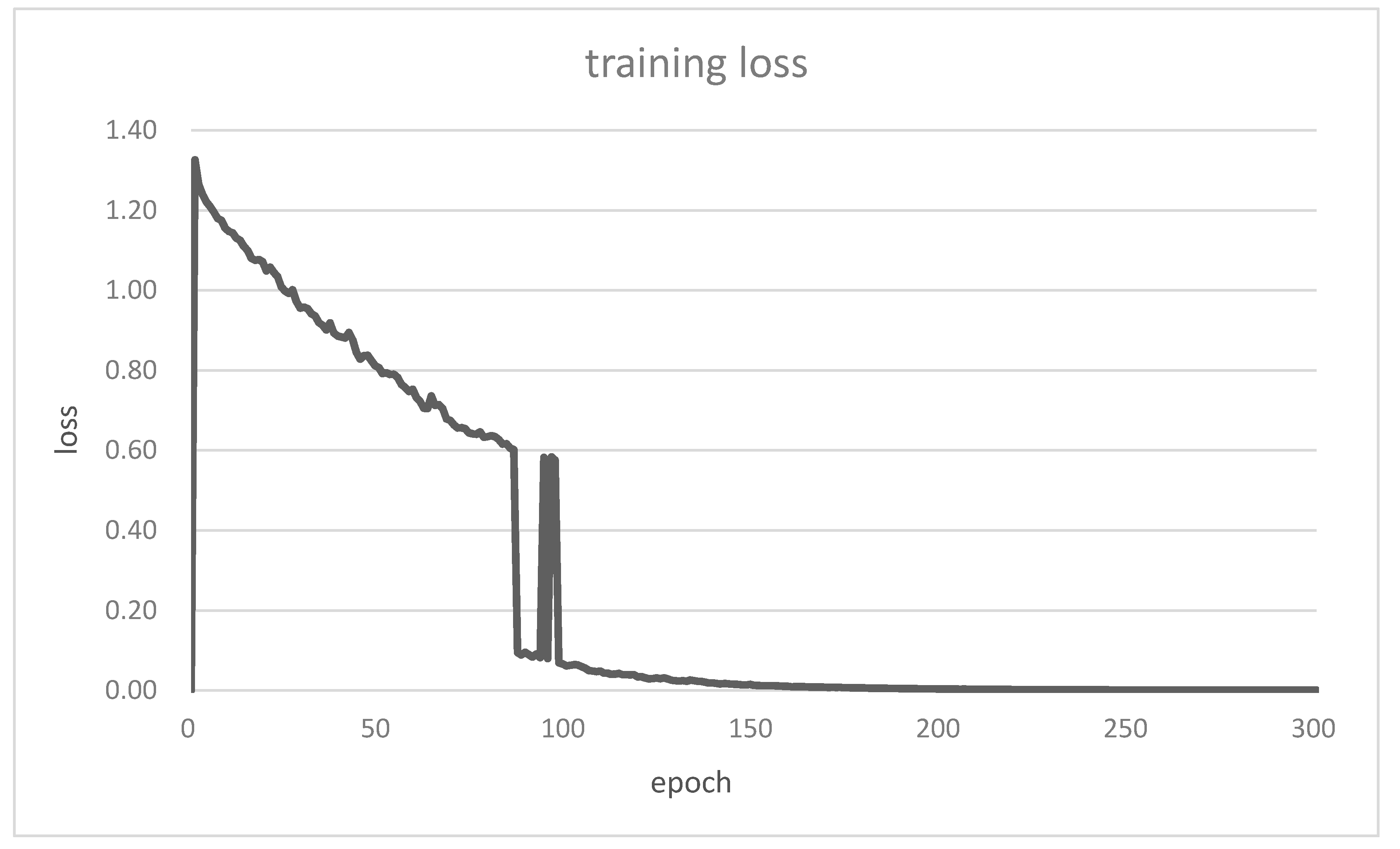
The video content type in the simulation results is as follows. The video is a travel documentary of CIF size and of length 50 s at 30 fps [13,15]. Each user has different starting time of the same cyclic video. In this way, application layer diversity for users is created and the complexity over time for users is the same. The size of a GOP (time slot) is 15 frames. The resource allocation is conducted once per GOP. The source encoding rate control is H.264/AVC baseline profile, and 80~600 kbps for each GOP.
The signal bandwidth is BW = 50 kHz, and the adaptive modulation method is M-QAM with M = 4~256. The users randomly located and their channel gains are also random. The channel gain is modeled as α rayleigh 2 · K 0 · ( d 0 d k ) γ . where α rayleigh is Rayleigh fading and γ is the path loss exponent. K 0 is −24 dB, d k is uniformly distributed [40 m, 100 m], and d 0 is 40 m. The maximum transmitting power per user P max is 24 dBm. The time varying channel response is assumed block fading. That is, the channel coefficients are constant during a GOP/time slot and are independently and identically distributed (i.i.d.) for different GOPs/time slots [13,15,16]. Additionally, Table 2 shows the parameters of the DNN. The activation function for the hidden layers is ReLU since it can keep the gradient at 1 and the size of gradients will not reduce exponentially when back-propagating via many layers [33]. The activation function for the output layers is sigmoid since the user selection in NOMA-MIMO systems is a multi-label classification. The number of epochs is selected based on the training/validation loss curve convergence in Figure 4 and Figure 5.
The following schemes are considered for comparison.
Scheme Optimal: the optimal scheme (the exhaustive search bound).
Scheme DNN (proposed): Proposed DNN, learning from Scheme Optimal (optimal training data).
Scheme A: [13], sub-optimal scheme, state-of-the-art
Scheme A’: DNN, but learning from Scheme A (sub-optimal training data)
Scheme B: [12], sub-optimal scheme, state-of-the-art
Scheme C: The OMA system.
The model validation and credibility of the simulation results for proposed Scheme DNN are justified as follows. The training loss and validation loss versus epochs are shown in Figure 4 and Figure 5, respectively. The following is observed:
(1)
The loss function converges after 200 epochs, so the epochs = 200 in Table 2.
(2)
The validation loss converges to almost zero in a way as the training loss, and no overfitting occurs. The DNN model can learn the correct answer from the unseen data (the validation data are different from the training data). This validates the DNN system model with the parameters in Table 2.
(3)
The initial loss is greater than 1 (maximum of the binary cross entropy). Also, there are jumps of 0.5 (constraint violation) before convergence (about epoch 100) in the training and validation loss curves. These validate the L o s s c o n s t r a i n t in (20) in the DNN system model.
The comparison metrics are the theoretical and simulated PSNR. The theoretical PSNR is obtained by using MSE in (14) and (15). The simulated PSNR is obtained by using MSE in the simulation and accounts for channel-induced errors, imperfect source encoding rate control etc. [15]
Figure 6 shows the average theoretical PSNR of all schemes. Obviously, the proposed Scheme Optimal has perform best. The proposed Scheme DNN, which learns from the optimal solution, outperforms the previous suboptimal Schemes A and B by 0.7 dB and 2.3 dB, respectively, and is only 0.4 dB away from the Scheme Optimal. Scheme D, an OMA scheme, has the lowest 29.0 dB among all schemes.
In Figure 7, the simulated PSNR of all schemes are all lower than the corresponding theoretical PSNR. This is due to the fact that of the communication channel errors, imperfect rate control at the source encoder, etc. [15,16]. The complexity of Scheme Optimal is too high so its simulated PSNR can’t be achieved. It can be seen that the proposed Scheme DNN outperforms Schemes A and B by 0.8 dB and 2.0 dB, respectively.
Scheme DNN and Scheme A’ are compared in Figure 6 and Figure 7. Scheme DNN uses DNN to learn from the optimal scheme (Scheme Optimal) and Scheme A’ use DNN to learn for sub-optimal scheme. Scheme DNN and Scheme A’ use the same the DNN structure but different training data (from Scheme Optimal or Scheme A). Scheme DNN outperforms Scheme A’ by 1.6 dB and 1.8 dB in the theoretical and simulated PSNR, respectively.
The DNN architecture, a computational model composed of more than one hidden layer, learns to represent data with multiple abstraction levels, in a similar way to human brains [35]. A more complicated problem needs more hidden layers in a neural network to solve it. For an ordinary neural network (number of hidden layers = 1), the theoretical PSNR is 30.2 dB and significantly worse than the deep neural network (Scheme DNN in Figure 6, number of hidden layers = 4). Thus, DNN is more useful than ordinary neural network in a complicated cross-layer user selection in uplink NOMA-MIMO video transmissions.

Discussions

The proposed DNN model details and why it is a good solution are as follows. The number of neurons at 4 hidden layers is 1024/1024/1024/2048. The input is the normalized channel gains [32] (physical layer) and RD-function parameters (application layer) of all users. DNN model parameters such as number of hidden layers, number of neurons at each hidden layer, etc., are determined by exhaustive search [18]. The DNN model quality is quantitively indicated by the training loss and validation loss [36,37,38]. In Figure 4, the training loss converges to almost zero after 200 epochs, so there is no underfitting and the DNN model is not too simple. In Figure 5, the validation loss also converges to almost zero in a way as with the training loss, so there is no overfitting and the DNN model is not too complex. Therefore, the DNN model is identified as a good one.
Next, the performance is discussed and better presentation of simulation results is given. The training and validation loss in Figure 4 and Figure 5 show convergence before 200 epochs and no underfitting/overfitting. The parameter setting in Table 2 in the revised manuscript (Table 1 in the original manuscript) including the DNN size, epochs, training data size, etc. is appropriate. The jumps of 0.5 and greater-than-1 value of initial loss indicate the modified loss function in (20) with L o s s c o n s t r a i n t   = 0.5. The proposed Scheme DNN outperforms prior work suboptimal Scheme A [13] by 0.7 dB and only 0.4 dB away from Scheme Optimal in theoretical PSNR in Figure 6 since it learns from the optimal Scheme Optimal. For comparison, Scheme A’ learns from suboptimal Scheme A and slightly underperforms Scheme A. The simulated PSNR is obtained by using MSE in the simulation, which accounts for channel-induced errors, imperfect source encoding rate control etc. The proposed Scheme DNN outperforms the prior work suboptimal Scheme A by 0.8 dB in more realistic simulated PSNR in Figure 7. Again, the proposed Scheme DNN learns from the optimal, so it can surpass the suboptimal Scheme A.
Next the computational complexity is discussed. First, note that the training stage is executed beforehand (offline), so it is not an obstacle for the real-time (online) operation of the deep learning-based scheme [19]. Deep learning-based resource allocation decisions could be obtained with much less online computations than the non-deep-learning-based resource allocation schemes [28]. Thus, as in [18,19,20,28], the training time is excluded in the computational complexity comparison where only online (testing stage) computational complexity is counted since the training procedure is conducted offline. For K = 12 and N = 2, the execution time of Scheme Optimal for 3000 testing data is over 15 min. The execution time (testing stage only, not including training stage) of Scheme DNN is 14.86 s for the same 3000 testing data. The schemes are performed in a desktop computer with Intel Core I7-8700 NVIDIA 1080Ti GPU. For each testing data (resource allocation in one GOP), the proposed Scheme DNN requires only 5 ms and the Scheme Optimal requires 300 ms.
Lastly, the comparison among different video samples is needed in order to evaluate the performance of the overall adopted methodology (such as the modified loss function). It allows to evaluate the solution scalability to other cases and then to evaluate the goodness of DNN model. We simulate PSNR for other video sequences in CIF resolution with 30 fps in [39]. Although the absolute values of the simulated PSNR differs for different video samples, the relative performance gain among schemes are similar.

6. Conclusions

A DNN structure with the modified loss function to learn the optimal user selection scheme is proposed. The loss function modification is to skip the post-processing of the DNN output (and the corresponding complexity and delay) during the testing stage. The numerical results show that the proposed DNN-based approach learning from the optimal user selection (by exhaustive search) outperforms the state-of-the-art [13] and [12] by 0.7 dB and 2.3 dB in theoretical PSNR, respectively, and is only 0.4 dB less than the optimal solution. The proposed Scheme DNN using the results from the optimal user selection as the training data is 1.8 dB higher in theoretical PSNR than Scheme A’ using the results from the sub-optimal user selection as the training data. The proposed Scheme DNN has 60 times lower computational complexity during the testing stage than the optimal scheme (Scheme Optimal) since each layer of the DNN is just a linear combination and a non-linear activation function. and may benefit a low latency scenario for the next generation communication systems. Previously, the deep learning-based resource allocation schemes all learned from the sub-optimal scheme so they cannot outperform the sub-optimal scheme. In the paper, the proposed deep learning-based scheme learns from the optimal scheme, and offers near-optimal video quality at much less computational complexity. It may be beneficial for next generation multimedia communications to increase the quality of user experience.

Author Contributions

Conceptualization, methodology, and formal analysis, S.-M.T.; software and data curation, S.-C.K. All authors have read and agreed to the published version of the manuscript.

Funding

This research was funded by Ministry of Science and Technology, grant number MOST 109-2221-E-027-087.

Acknowledgments

The authors thank Kun-Lin Lu for obtaining performance figures and Jun-Jie Wu for proofreading the final version of the paper.

Conflicts of Interest

The authors declare no conflict of interest.

References

  1. Chen, Z.; Zhang, X.; Xu, Y.; Xiong, J.; Zhu, Y.; Wang, X. MuVi: Multiview Video Aware Transmission Over MIMO Wireless Systems. IEEE Trans. Multimed. 2017, 19, 2788–2803. [Google Scholar] [CrossRef]
  2. Yang, Y.-S.; Pu, J.-W.; Yeh, P.-H.; Li, C.-P.; Li, H.-J. Investigation on Distributed User Selection for Uplink Multicell Systems with MIMO. In Proceedings of the 2015 IEEE 81st Vehicular Technology Conference (VTC Spring), Glasgow, UK, 11–14 May 2015; pp. 1–5. [Google Scholar]
  3. Lee, K.; Kim, D. Cross-layer optimization for heterogeneous MU-MIMO/OFDMA networks. Sensors 2021, 21, 2744. [Google Scholar] [CrossRef]
  4. Gui, G.; Huang, H.; Song, Y.; Sari, H. Deep learning for an effective non orthogonal multiple access scheme. IEEE Trans. Veh. Technol. 2018, 67, 8440–8450. [Google Scholar] [CrossRef]
  5. Jiao, R.; Dai, L.; Zhang, J.; MacKenzie, R.; Hao, M. On the Performance of NOMA-Based Cooperative Relaying Systems Over Rician Fading Channels. IEEE Trans. Veh. Technol. 2017, 66, 11409–11413. [Google Scholar] [CrossRef] [Green Version]
  6. Gui, G.; Sari, H.; Biglieri, E. A New Definition of Fairness for Non-Orthogonal Multiple Access. IEEE Commun. Lett. 2019, 23, 1267–1271. [Google Scholar] [CrossRef]
  7. Gui, G.; Liu, M.; Tang, F.; Kato, N.; Adachi, F. 6G: Opening New Horizons for Integration of Comfort, Security, and Intelligence. IEEE Wirel. Commun. 2020, 27, 126–132. [Google Scholar] [CrossRef]
  8. Zhang, L.; Wu, Y.; Li, W.; Rong, B.; Salehian, K.; LaFleche, S.; Wang, X.; Park, S.I.; Kim, H.M.; Lee, J.-Y.; et al. Layered-Division-Multiplexing for High Spectrum Efficiency and Service Flexibility in Next Generation ATSC 3.0 Broadcast System. IEEE Wirel. Commun. 2019, 26, 116–123. [Google Scholar] [CrossRef]
  9. Ding, Z.; Liu, Y.; Choi, J.; Sun, Q.; Elkashlan, M.; Chih-Lin, I.; Poor, H.V. Application of Non-Orthogonal Multiple Access in LTE and 5G Networks. IEEE Commun. Mag. 2017, 55, 185–191. [Google Scholar] [CrossRef] [Green Version]
  10. Li, H.; He, W.; He, Q.; He, J. The application and development of SIC technology in wireless communication system. In Proceedings of the 2017 IEEE 9th International Conference on Communication Software and Networks (ICCSN), Guangzhou, China, 6–8 May 2017; pp. 565–570. [Google Scholar]
  11. Senel, K.; Cheng, H.V.; Bjornson, E.; Larsson, E.G. What Role can NOMA Play in Massive MIMO? IEEE J. Sel. Top. Signal. Process. 2019, 13, 597–611. [Google Scholar] [CrossRef] [Green Version]
  12. Kim, B.; Chung, W.; Lim, S.; Suh, S.; Kwun, J.; Choi, S.; Hong, D. Uplink NOMA with multi-antenna. In Proceedings of the 2015 IEEE 81st Vehicular Technology Conference (VTC Spring), Glasgow, UK, 11–14 May 2015; pp. 1–5. [Google Scholar]
  13. Tseng, S.-M.; Chen, Y.-F.; Fang, H.-H. Cross PHY/APP layer user grouping and power allocation for uplink multi-antenna NOMA video communication systems. IEEE Syst. J. 2020, 14, 3351–3359. [Google Scholar] [CrossRef]
  14. Qureshi, S.; Hassan, S.A. MIMO uplink NOMA with successive bandwidth division. In Proceedings of the 2016 IEEE Wireless Communications and Networking Conference Workshops (WCNCW), Doha, Qatar, 3–6 April 2016; pp. 481–486. [Google Scholar]
  15. Wang, D.; Toni, L.; Cosman, P.; Milstein, L.B. Uplink Resource Management for Multiuser OFDM Video Transmission Systems: Analysis and Algorithm Design. IEEE Trans. Commun. 2013, 61, 2060–2073. [Google Scholar] [CrossRef]
  16. Li, F.; Wang, T.; Cosman, P.C. Joint rate adaptation and resource allocation for real-time H.265/HEVC video transmission over uplink OFDMA systems. Multimed. Tools Appl. 2019, 78, 26807–26831. [Google Scholar] [CrossRef] [Green Version]
  17. Simeone, O. A Very Brief Introduction to Machine Learning with Applications to Communication Systems. IEEE Trans. Cogn. Commun. Netw. 2018, 4, 648–664. [Google Scholar] [CrossRef] [Green Version]
  18. Kim, M.; Kim, N.-I.; Lee, W.; Cho, D.-H. Deep Learning-Aided SCMA. IEEE Commun. Lett. 2018, 22, 720–723. [Google Scholar] [CrossRef]
  19. Lee, W.; Kim, M.; Cho, D.-H. Deep Learning Based Transmit Power Control in Underlaid Device-to-Device Communication. IEEE Syst. J. 2019, 13, 2551–2554. [Google Scholar] [CrossRef]
  20. Ahmed, I.; Khammari, H. Joint machine learning based resource allocation and hybrid beamforming design for massive MIMO systems. In Proceedings of the 2018 IEEE Globecom Workshops (GC Wkshps), Abu Dhabi, United Arab Emirates, 9–13 December 2018; pp. 1–6. [Google Scholar]
  21. Kim, Y. Application of machine learning to antenna design and radar signal processing: A review. In Proceedings of the 2018 International Symposium on Antennas and Propagation (ISAP), Busan, Korea, 23–26 October 2018; pp. 1–2. [Google Scholar]
  22. Sun, H.; Chen, X.; Shi, Q.; Hong, M.; Fu, X.; Sidiropoulos, N.D. Learning to Optimize: Training Deep Neural Networks for Interference Management. IEEE Trans. Signal Process. 2018, 66, 5438–5453. [Google Scholar] [CrossRef]
  23. López, D.; Rivas, E.; Gualdron, O. Primary user characterization for cognitive radio wireless networks using a neural system based on Deep Learning. Artif. Intell. Rev. 2019, 52, 169–195. [Google Scholar] [CrossRef]
  24. Wang, Y.; Ye, Z.; Wan, P.; Zhao, J. A survey of dynamic spectrum allocation based on reinforcement learning algorithms in cognitive radio networks. Artif. Intell. Rev. 2018, 51, 493–506. [Google Scholar] [CrossRef]
  25. Tseng, S.-M.; Chen, Y.-F.; Tsai, C.-S.; Tsai, W.-D. Deep-Learning-Aided Cross-Layer Resource Allocation of OFDMA/NOMA Video Communication Systems. IEEE Access 2019, 7, 157730–157740. [Google Scholar] [CrossRef]
  26. Wang, P. Outage Capacity Considered Supervised Learning Based NOMA OFDMA Video Communication Resource Allocation. Master’s Thesis, Department of Electronic Engineering, National Taipei University of Technology, Taipei, Taiwan, 2021. [Google Scholar]
  27. Liu, M.; Song, T.; Hu, J.; Yang, J.; Gui, G. Deep Learning-Inspired Message Passing Algorithm for Efficient Resource Allocation in Cognitive Radio Networks. IEEE Trans. Veh. Technol. 2018, 68, 641–653. [Google Scholar] [CrossRef]
  28. Ahmed, K.I.; Tabassum, H.; Hossain, E. Deep Learning for Radio Resource Allocation in Multi-Cell Networks. IEEE Netw. 2019, 33, 188–195. [Google Scholar] [CrossRef] [Green Version]
  29. Huang, H.; Guo, S.; Gui, G.; Yang, Z.; Zhang, J.; Sari, H.; Adachi, F. Deep Learning for Physical-Layer 5G Wireless Techniques: Opportunities, Challenges and Solutions. IEEE Wirel. Commun. 2020, 27, 214–222. [Google Scholar] [CrossRef] [Green Version]
  30. Mao, Q.; Hu, F.; Hao, Q. Deep Learning for Intelligent Wireless Networks: A Comprehensive Survey. IEEE Commun. Surv. Tutor. 2018, 20, 2595–2621. [Google Scholar] [CrossRef]
  31. Stuhlmuller, K.; Farber, N.; Link, M.; Girod, B. Analysis of video transmission over lossy channels. IEEE J. Sel. Areas Commun. 2000, 18, 1012–1032. [Google Scholar] [CrossRef]
  32. Lee, W. Resource Allocation for Multi-Channel Underlay Cognitive Radio Network Based on Deep Neural Network. IEEE Commun. Lett. 2018, 22, 1942–1945. [Google Scholar] [CrossRef]
  33. Glorot, X.; Bordes, A.; Bengio, Y. Deep sparse rectifier neural networks. In Proceedings of the 14th International Conference on Artificial Intelligence and Statistics, Fort Lauderdale, FL, USA, 11–13 April 2011; pp. 315–323. [Google Scholar]
  34. Jing, X.Y.; Zhang, X.; Zhu, X.; Wu, F.; You, X.; Gao, Y.; Shan, S.; Yang, J.Y. Multiset feature learning for highly imbalanced data classification. IEEE Trans. Pattern Anal. Mach. Intell. 2021, 43, 139–156. [Google Scholar] [CrossRef] [PubMed]
  35. LeCun, Y.; Bengio, Y.; Hinton, G.E. Deep learning. Nature 2015, 521, 436–444. [Google Scholar] [CrossRef] [PubMed]
  36. General Guidance Hung-Yi Lee. Available online: https://speech.ee.ntu.edu.tw/~hylee/ml/ml2021-course-data/overfit-v6.pptx (accessed on 9 September 2021).
  37. CS231n: Convolutional Neural Networks for Visual Recognition Stanford—Spring 2021. Available online: https://cs231n.github.io/neural-networks-3/#eval (accessed on 9 September 2021).
  38. Goodfellow, I.; Bengio, Y.; Courville, A. Deep Learning; MIT Press: Cambridge, MA, USA, 2017. [Google Scholar]
  39. Lin, K.; Dumitrescu, S. Cross-layer resource allocation for scalable video over OFDMA wireless networks: Tradeoff between quality fairness and efficiency. IEEE Trans. Multimed. 2017, 19, 1654–1669. [Google Scholar] [CrossRef]
Figure 1. The structure of the uplink NOMA-MIMO video communication system with K users, N antennas at the BS.
Symmetry 13 01737 g001
Figure 2. Uplink NOMA-MIMO system model. K users, N antennas at the BS, 2 N users can be supported, K > 2 N [12,13].
Symmetry 13 01737 g002
Figure 3. The deep neural network (DNN) system model. structure.
Symmetry 13 01737 g003
Figure 4. The loss vs. epochs in the training stage.
Symmetry 13 01737 g004
Figure 5. The loss vs. epochs in the validation stage.
Symmetry 13 01737 g005
Figure 6. The theoretical PSNR of all schemes, SNR = 15 dB, 12 users. Scheme DNN is the proposed scheme.
Symmetry 13 01737 g006
Figure 7. The simulated PSNR of all schemes, SNR = 15 dB, 12 users. Scheme DNN is the proposed scheme.
Symmetry 13 01737 g007
Table 1. Comparisons of NOMA-MIMO systems.
[12][13]Proposed
User selectionBase on physical layer metric information rate in (9) and (13)Base on ross layer metric video MSE in (14)Learn from [13]
Power allocationBase on physical layer metric information rate in (9) and (13)Base on cross layer metric video MSE in (14)the same as [13]
Computational complexityIterative algorithm, so high computation complexityIterative algorithm, so high computation complexityNon-iterative, deep learning-based approach, so low online computation complexity
Table 2. The parameters of the DNN.
ParameterValue
Batch size100
Learning Rate0.0001
Activation function (hidden layers)ReLU
Activation function (last layer)Sigmoid
Cost functionProposed modified cost function in (21)
Epochs200
Number of hidden layers4
Number of training data24,000
Number of validation data6000
Number of testing data3000
Publisher’s Note: MDPI stays neutral with regard to jurisdictional claims in published maps and institutional affiliations.

