1. Introduction
Low-density parity-check (LDPC) codes have been recognized for their excellent error correction abilities near the Shannon limit [
1], and LDPC codes are advantageous in hardware implementation [
2]. At present, many communication systems have taken these codes as standards, such as the Digital Video Broadcasting Satellite (DVB-S2/S2X, Europe) [
3], the Consultative Committee for Space Data Systems (CCSDS) [
4], Wireless Local Area Network (WLAN, IEEE 802.11n) [
5], the China digital radio standard [
6], and the 5th Generation Mobile Communication Technology (5G) [
7,
8].
Currently, research on mobile communication systems has entered the 5G phase [
9]. Channel encoding is one of the 5G core technologies; it is mainly used to ensure the correct transmission of channel information and to improve communication quality [
10]. The Third Generation Partnership Project (3GPP) organization has finally decided to take the LDPC code as the data channel coding scheme for 5G enhanced Mobile Broadband (eMBB) [
11,
12]. Compared to 4G, 5G has higher requirements in terms of the data transmission rate and information transmission reliability [
13,
14]. Therefore, it has important significance and application value for exploring a novel LDPC encoding scheme and implementing 5G LDPC codes [
15,
16]. To achieve scalable data transmission and flexibility, 3GPP has decided to take two kinds of base graphs for 5G channel encoding—
BG1 and
BG2 [
17].
Presently, some research initiatives have focused on 5G LDPC codes [
18,
19]. 5G New Radio (NR) has higher performance demands on channel coding solutions [
20]; one study discusses the design concept of the new quasi-cyclic low-density parity-check (QC-LDPC) codes that have different structural characteristics and meet the multiple requirements of 5G NR channel coding [
21]. Designed as structured LDPC codes, QC-LDPC codes have been research hotspots in the recent past. QC-LDPC codes possess obvious advantages in circuit implementations, and compared to other kinds of LDPC codes, QC-LDPC codes need fewer hardware resources [
22].
Owing to the sparsity of the parity-check matrix, the QC-LDPC encoder can be achieved with a low-complexity design. Despite LDPC codes being defined by a parity check matrix, it is difficult to directly realize a low-complexity LDPC encoder as their generator matrix is usually unknown. Some studies have been conducted to acquire low-complexity LDPC encoding. The direct encoding algorithm was originally proposed by Dr. Gallager [
23]. It is a general coding algorithm for linear block codes. The method directly uses C = S × G matrix to obtain the code word C (S represents information bits); its theory is simple, but its coding process is complex. The algorithm utilizes Gaussian elimination to transform the check matrix (
H matrix) into a generator matrix (G matrix). Its computation amount and the algorithm complexity are high, and the sparsity of the
H matrix is damaged in the process. The algorithm needs to store G matrix information in hardware circuits. The consumption of hardware resources is substantially large, so its hardware implementation is difficult. The LU algorithm [
24] uses the
H matrix to encode directly; it does not need to convert the
H matrix into a G matrix, and the
H matrix is split into an information bit matrix
Hs and a check bit matrix
HP. However, this method requires LU decomposition on the
HP matrix, that is,
H left-multiplies a permutation matrix A, and the determination of A is difficult, so the encoding algorithm is still complex. When the
H matrix is a singular matrix, it cannot realize LU decomposition, and the LU algorithm cannot be accomplished. The algorithm is also unsuitable for hardware implementation. The approximate lower triangular matrix encoding algorithm is an effective encoding method named as the RU algorithm [
25], which directly applies the
H matrix for encoding. The encoding complexity of the RU algorithm is lower than the direct encoding algorithm. The RU algorithm converts the check matrix
H into an approximate lower triangular matrix by row and column permutation under the condition of known information bits. The check bits are then obtained by using check equations. Finally, the information bits and check bits are connected in series to form the final codeword. A main disadvantage of the RU coding process is that there is no precise programmable step-by-step encoding algorithm. The multiple matrix computations within the RU algorithm obviously limit the design of a fast flexible encoder.
In 5G communication, in order to meet the needs of diverse communication scenarios, the 3GPP organization has considered the compatibility requirements for the characteristics of different scenarios when formulating the standards for 5G LDPC codes. The 5G LDPC standards contain two different base graphs, BG1 and BG2, which correspond to two different base matrices, HBG1 and HBG2. In addition, each base matrix has two sub-matrices B (corresponding to core parity bits), that is, the base matrices of 5G LDPC codes can be further divided into four base matrices.
Although Reference [
26] introduces a QC-LDPC encoding structure, its encoding scheme only considers the case of one submatrix B in a single base graph. The paper does not research the significant requirements of encoding compatibility for 5G LDPC codes, which cannot meet the practical application conditions in different scenarios. Reference [
6] introduces the encoding approach of CDR LDPC codes. Combining the characteristics of the generation matrix and the check matrix, it designs a hardware-friendly encoding method. In addition, it adopts an optimized control and storage design in implementing the four LDPC codes specified by CDR standard. Reference [
22] introduces hardware architectures for encoding QC-LDPC codes, which is based on the features of recursively-constructed QC-LDPC codes. It takes LU decomposition, involved matrices need to be precomputed, compressed and stored in encoding memories. Reference [
27] proposes two encoding architectures which can support several code lengths for different applications. The design can realize the requirements for different encoding parameters. Reference [
28] proposes a fully parallel LDPC encoder based on reduced complexity XOR trees; it is designed for the IEEE 802.11n standards. Reference [
29] introduces a method to improve hardware multiplication based on constant matrices in GF(2); it tries to apply the method to the QC-LDPC encoding algorithm. Reference [
30] describes that the throughput of QC-LDPC codes could be improved by trimming the full-base matrix into the requested matrix size.
For high performance and compatibility of 5G LDPC encoding requirements, this work presents a highly area-efficient parallel QC-LDPC encoder core with compatible architecture, which is compatible with the latest 5G standard. It has high encoding performance and a low hardware cost.
The remaining sections of this paper are organized as follows:
Section 2 briefly analyzes the characteristics of 5G LDPC codes.
Section 3 proposes a high parallel LDPC encoding algorithm compatible with 5G LDPC codes.
Section 4 shows a high area-efficient parallel QC-LDPC encoder with compatible architecture.
Section 5 gives experimental results and comparative analysis.
Section 6 summarizes our work and provides the conclusions.
2. Analysis of 5G LDPC Codes
LDPC codes are adopted as the data encoding scheme of 5G because its higher encoding throughput and lower latency can better adapt to the data transmission of high-speed services. The main content of 5G LDPC standards is analyzed progressively as follows.
The LDPC codes in 5G standards are QC-LDPC codes. For one QC-LDPC code, the structural characteristics of the check matrix can be denoted by a base graph (BG) or a base graph matrix (
HBG), as exampled by the check matrix in Equation (1).
HBG is a base graph matrix associated with the check matrix
H.
In the matrix above, each 1 in HBG represents a 4 × 4 binary circulant permutation matrix (CPM), and each 0 represents a 4 × 4 zero matrix; that is, the size Z of the matrix in Equation (1) is 4. The HBG of each QC-LDPC code intuitively indicates the position of the CPM in the check matrix by the distributions of elements ‘1’, providing an important reference in the encoder design of corresponding codes.
HBG can represent the structural characteristics of the check matrix of one QC-LDPC code. However, it cannot reflect the cyclic shift value of each CPM. Therefore, it is essential to define a cyclic shift coefficient matrix
P (exponent matrix) to represent the cyclic shift value of the corresponding base graph matrix.
There are two values of Pm,n. When 0 ≤ Pm,n < Z, it denotes the cyclic permutation matrix obtained with a Z × Z submatrix right-shifting by Pm,n bits. When Pm,n = −1, it denotes a Z × Z zero matrix.
Equation (1) corresponds to the cyclic shift coefficient matrix
P, which is shown as follows:
Therefore, the check matrix is unique if the lifting size Z and the exponent matrix P of one QC-LDPC code are determined. The description of 5G LDPC codes often adopts this representation method.
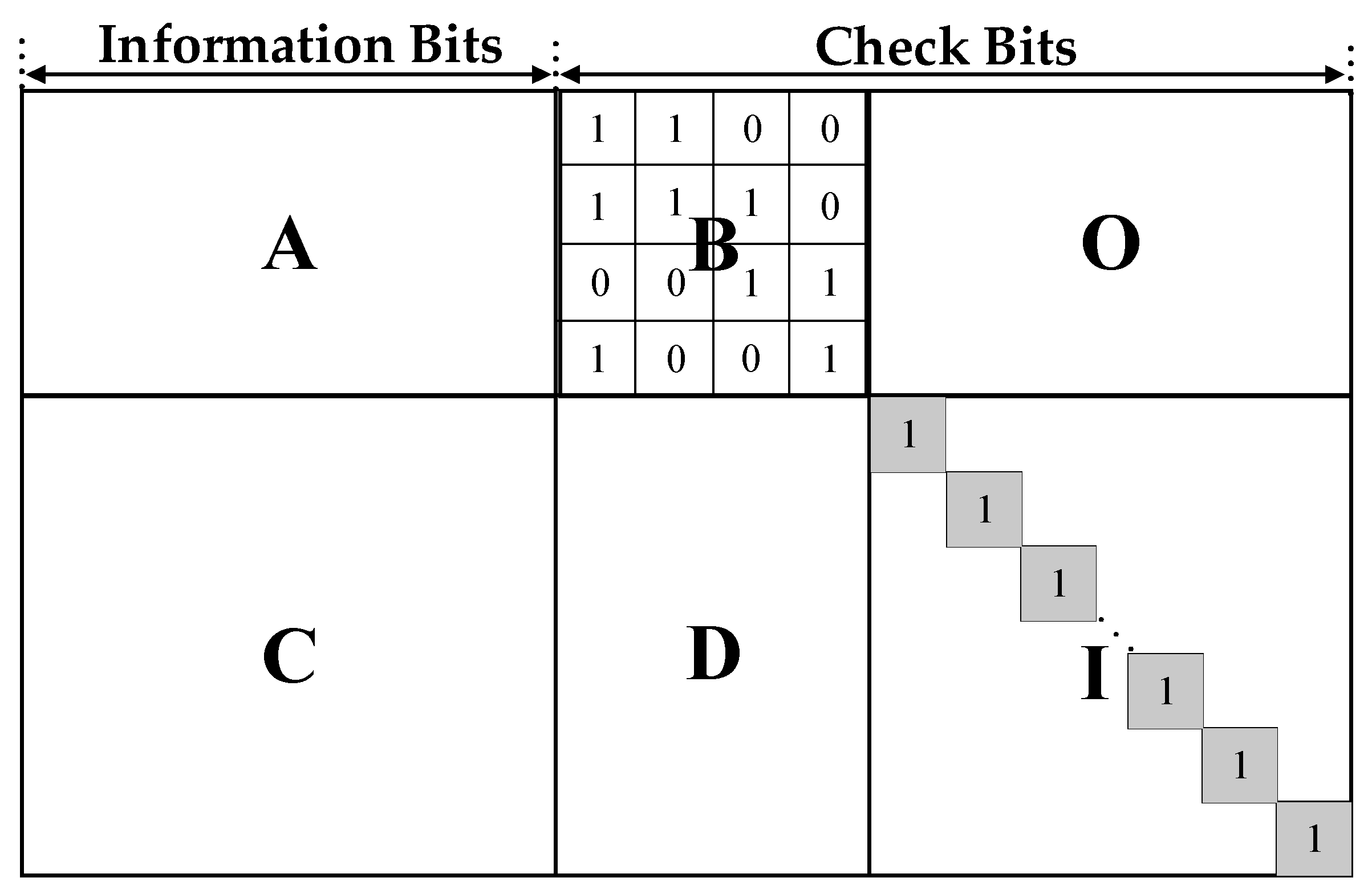
In the 5G standard, LDPC codes have two types of base graphs, named BG1 and BG2. Check matrices of BG1 and BG2 both have the characteristic structure shown as
Figure 1. These check matrices are termed H matrices.
The 5G LDPC code has two types of base matrices, namely,
HBG1 and
HBG2. Their information comparison is shown in
Table 1.
BG1 has a total of 316 elements 1 while BG2 has a total of 197 elements 1. The element 1 indicates that the corresponding submatrix is an identity matrix or a cyclic right shift identity matrix. The element 0 indicates that the corresponding submatrix is a zero matrix. Cyclic shift coefficients of submatrices in H are stored in the corresponding coefficient matrix. The coefficient matrix has the same size as the HBG matrix. In the cyclic shift coefficient matrix, the non-negative element i corresponds to the element 1 in the HBG, indicating that the submatrix is the matrix obtained after an identity matrix is cyclically right shifting by i bits. The element −1 corresponds to the element 0 in the HBG, indicating that the corresponding submatrix is a zero matrix.
The size
Z of the submatrix in the
H is not fixed. The 5G standards specify the values of
Z. For BG1 and BG2, the value ranges of
Z are the same, as shown in
Table 2.
In 5G standards, the cyclic shift coefficients of the submatrices vary in different situations. First, BG1 and BG2 have different coefficient matrices; furthermore, different values of ‘a’ in
Table 2 will result in diverse coefficient matrices even in the same base matrix.
As shown in
Table 2, each row of the size
Z has the same cyclic shift coefficient matrix, so the size
Z can be divided into 8 sets, each of which shares a common coefficient matrix. The
Z values after division are shown in
Table 3.
When a
Z value in one set is taken as the size of each submatrix, the coefficient matrix corresponding to the set can be taken to represent the entire
H matrix. Equation (5) indicates the final cycle shift coefficients corresponding to different
Z values in the same set:
where
Vij denotes the element in the
i-th row and the
j-th column of the coefficient matrix corresponding to one set.
Pij denotes the actual cyclic shift coefficient of the submatrix corresponding to the elements in the i-th row and the
j-th column of the
HBG for a selected Z in one set.
3. Parallel LDPC Encoding Algorithm Compatible with 5G LDPC Codes
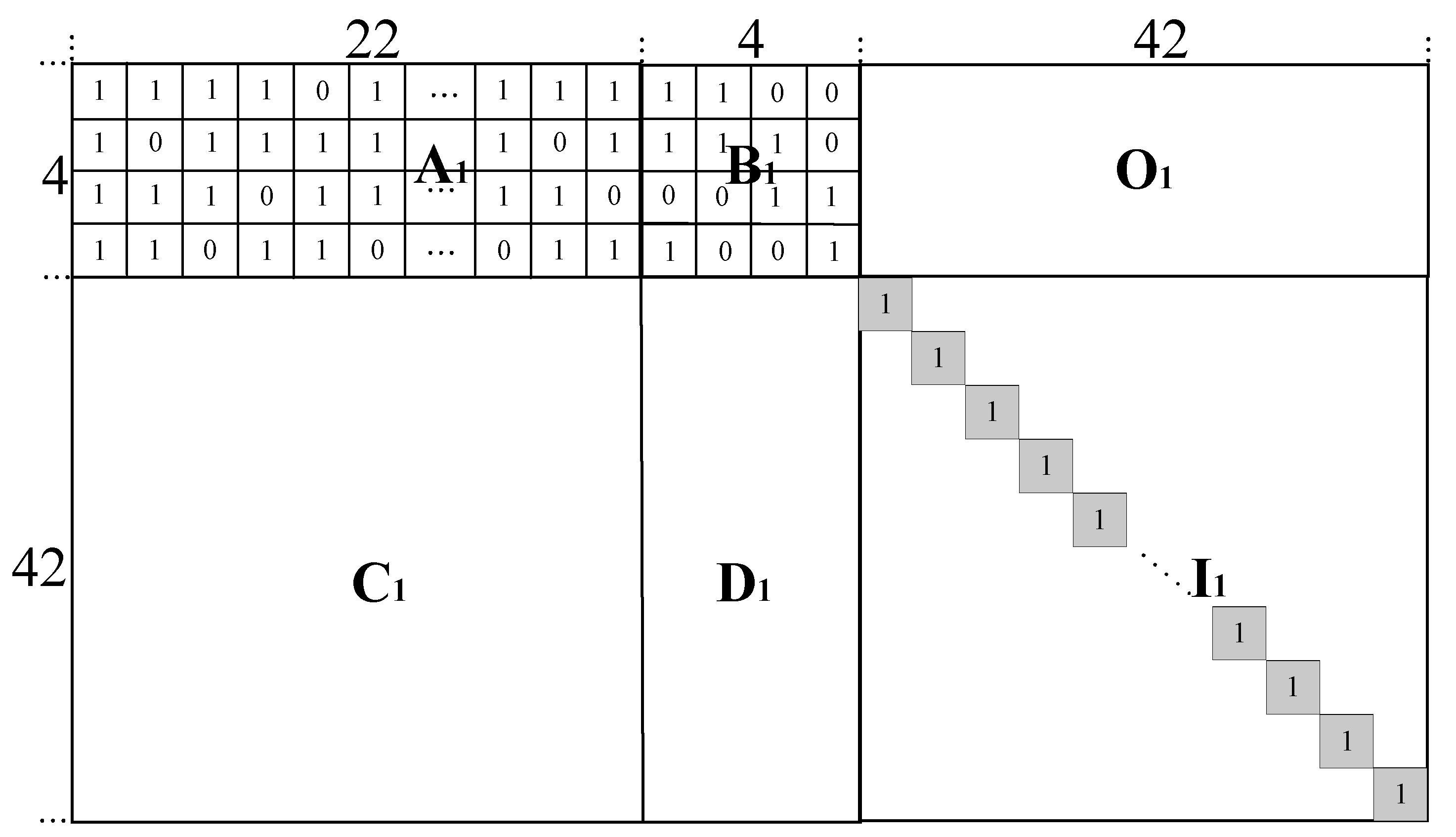
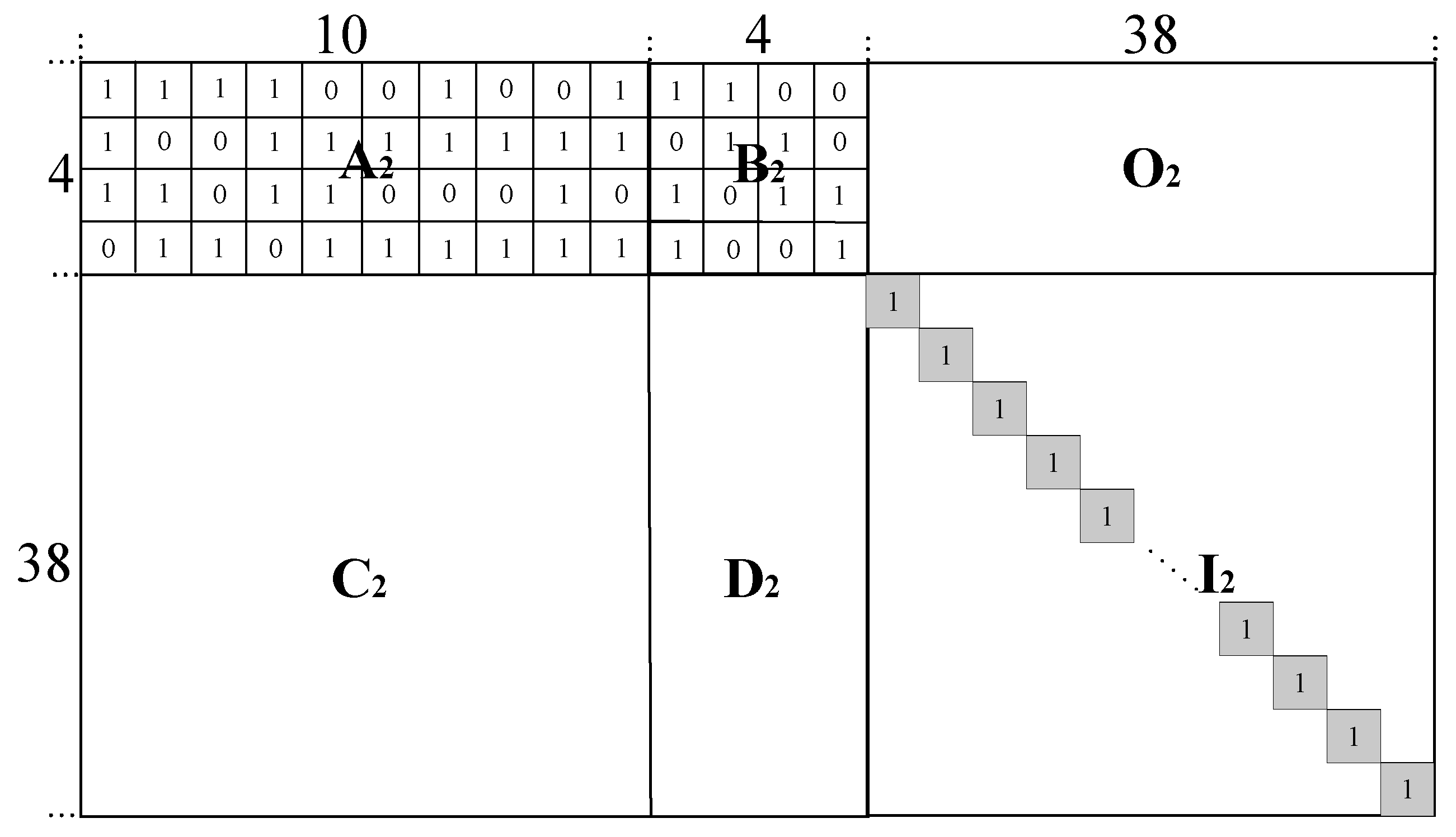
This paper proposes a high parallel QC-LDPC encoding algorithm, which is compatible with 5G LDPC standards. Based on this algorithm, a novel encoder architecture for LDPC codes is designed to satisfy the requirements of 5G LDPC codes mentioned above. There are two base graphs for 5G LDPC codes, BG1 and BG2. These base graphs have different structures, as shown in
Figure 2 and
Figure 3. Our research is compatible with both BG1 and BG2, this work has wide applicability to the new 5G LDPC standards. Furthermore, we present an integrated solution of the parallel LDPC encoding algorithm and the area-efficient compatible encoder architecture.
As shown in the two figures, the check matrix H is divided into multiple sub-blocks. BG1 and BG2 have different base graphs. BG1 is mainly used for high-performance encoding scenarios. Taking BG1 as an example, the size of HBG1 is 46 × 68. For the sub-blocks A, B, O, C, D and I, their sizes are 4 × 22, 4 × 4, 4 × 42, 42 × 22, 42 × 4, 42 × 42. Since the lifting size of HBG is Z, the codeword C is uniformly divided by the size Z to match the base matrix HBG. According to the sub-block structure of HBG, C can be denoted as C = [S1,…, Skb, Pa1,…, Pa4, Pb1,…, Pb(Mb−4)]. The column number of information sequence S is as same as the column numbers of block A and block C. The column number of the check sequence Pa is as same as those of block B and block D. The column number of the check sequence Pb is as same as those of block O and block I.
The encoding of 5G LDPC codes is defined by
H ×
CT =
OT, which can be expressed as the following.
(1) First, Equation (6) is decomposed into the following equation set.
(2) Then,
Pa and
Pb are calculated as follows.
Equation (8) shows that there are factors in the
α·βT form during the calculation of the check bits
Pa and
Pb, such as
A·ST,
C·ST, and
D·PT. However, during the calculation of
Pa, there is an additional matrix multiplication between
B−1 and
A·ST. Considering the characteristics of the cyclic shift coefficients in the
B block, let
Var = A·ST,
A is the submatrix of
H with known coefficients, and
S is the bit sequence of input information.
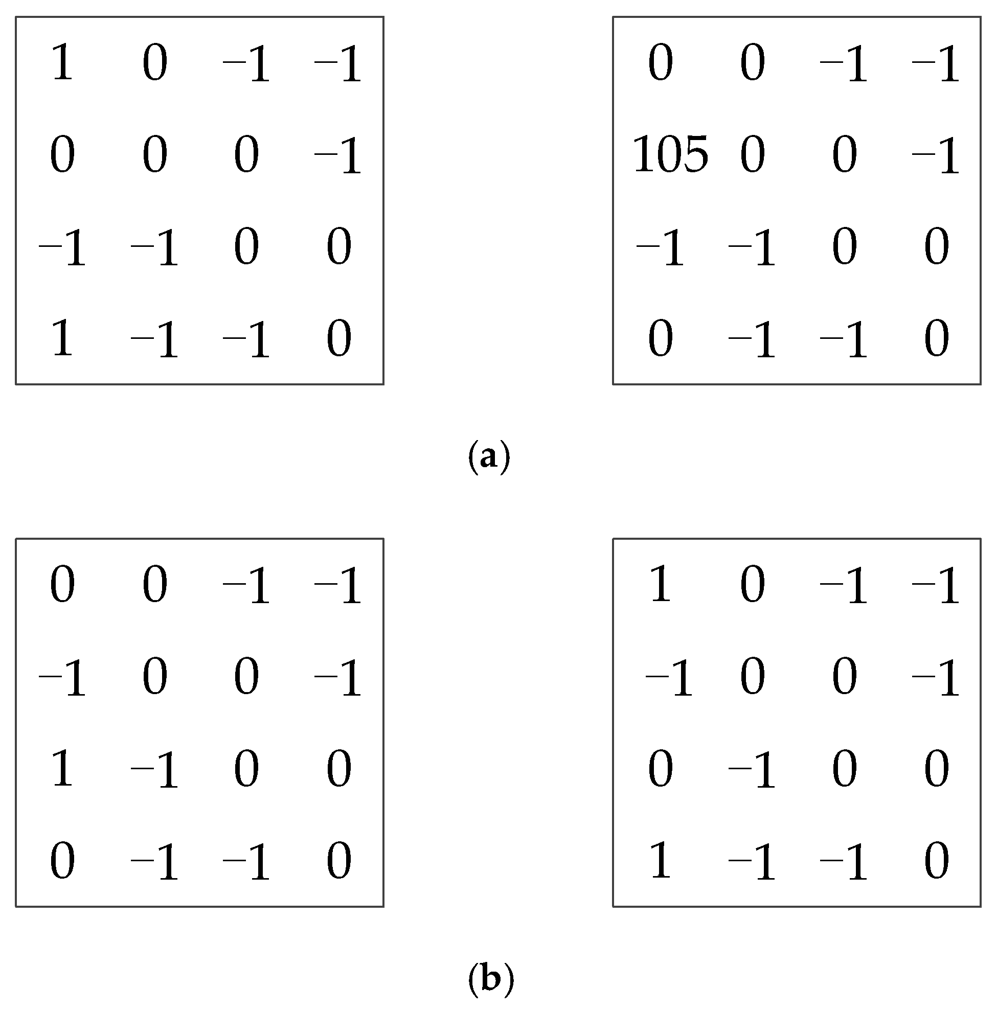
For
BG1 and
BG2, there are four different cases of circular shift coefficients corresponding to the
B submatrices of
HBG matrices, which are shown as
Figure 4a,b.
In Equation (7), A·ST + B·PaT = 0, so [var1, var2, var3, var4] and [Pa1, Pa2, Pa3, Pa4] have the following equation relationships.
The computational process of
Pa and
Var corresponding to the left submatrix of
Figure 4a is as follows:
The computational process of
Pa and
Var corresponding to the left submatrix of
Figure 4b is as follows:
The computational process of
Pa and
Var corresponding to the right submatrix of
Figure 4a is as follows:
The computational process of
Pa and
Var corresponding to the right submatrix of
Figure 4b is as follows:
Finally, the check information bits
Pa and
Pb are obtained, and the encoded codeword
C is the output.
For the check matrix H with a special structure in 5G LDPC codes, our scheme elides the matrix inversion operations in encoding. The scheme directly utilizes the linear mathematical relationship between Var and Pa to obtain the check sequence Pa by computing the intermediate variable (Var represents A·ST), which simplifies the encoding process. Through the above equations, the scheme uses var1, var2, var3, and var4 to solve Pa1, Pa2, Pa3, and Pa4. Because Pa has been solved, C and D are both submatrices with known coefficients in HBG, and S is the known information sequence. We can then obtain Pb by PbT = C·ST + D·PaT. Finally, we can obtain the encoded codeword C = [S, Pa, Pb] by combining S, Pa, and Pb. With this LDPC encoding scheme, the presented encoder mainly includes α·βT operation units in its hardware implementation, it greatly reduces the hardware complexity of the encoder architecture, laying a foundation for the realization of the high area-efficiency encoder in this paper.
4. Area-Efficient Parallel Pipelined QC-LDPC Encoder with Compatible Architecture
Based on the encoding scheme of this paper, α·βT units are the main operation units of the proposed encoder. A·ST, C·ST, and D·PaT are all operation units in the form of α·βT. According to the quasi-cyclic characteristics of 5G QC-LDPC, one operation unit can process the α·βT operation (Z-bit) in parallel, that is, to complete the computation of a Z-bit sequence in VarT or PbT. For the HBG1, PaT and PbT have up to 46 column sequences, and each sequence is Z-bit, so HBG1 needs 46 α·βT operation units. For the HBG2, PaT and PbT have up to 42 column sequences, and HBG2 then needs 42 α·βT operation units. In order to make the proposed encoder fully support 5G LDPC codes, this encoder sets 46 operation units to compatible with HBG1 and HBG2, and the operation units are distributed in Var generation module and Pb generation module. Furthermore, the cyclic shift operation and the XOR operation are combined to replace the α·βT computation, avoiding complicated multiplication-accumulation operations required by a direct α·βT operating process. This design not only significantly reduces the complexity of encoder and the hardware costs, but also greatly improves the computing efficiency.
Based on the above analysis, this work has designed a high area-efficient parallel QC-LDPC encoder with compatible architecture, which is shown in
Figure 5. The encoder mainly consists of a serial-to-parallel information input buffer, a
Var generation module, a configurable
Pa generation module, a parallel
Pb generation module, a cyclic shift coefficient memory module, and an encoding controller.
The upper and middle encoding modules (Var module and Pa module) of the encoder correspond to the high code rate of LDPC encoding used to generate the Pa check bits. The Pb encoding module corresponds to the extended matrix region in H to generate extended check bits. By selecting the number of enabled Pb operation units, the length of Pb check bits can be adjusted to determine the code rate of the encoded codeword. Thus, the encoder architecture can adapt to different code rates of LDPC encoding.
4.1. Information Input Buffer
The information sequence S is input into the buffer, and the buffer sends the Z-bit information sequence to the Var operation units in the form of parallel output. The input buffer register is implemented by a register set, which contains two Z-bit registers. Due to the controller signal, when one register supplies the Z-bit Si sequence to Var generation units in parallel, another register can preload the next Si+1 sequence. This structure enables the encoder to read in the next information frame to be encoded during the encoding of the present information frame, which saves the information reading time and improves the throughput of the encoder.
4.2. Cyclic Shift Coefficient Memory Module
Based on the structure characteristics of H matrices for 5G LDPC codes, the proposed encoder only needs to store the cyclic shift coefficient values corresponding to the A, C, and D submatrices in the Flash ROM. The memory module for other submatrices can be omitted. The A, C and D submatrices correspond to A_Block, C_Block, and D_Block, respectively. Moreover, the proposed encoder does not need to store the specific content of the H matrix.
The structure of the
HBG1 is shown in
Figure 2. The sizes of the
A,
C, and
D submatrices are 4 × 22, 42 × 22, and 42 × 4, respectively. The cyclic shift coefficients of each row in
A or [
C,
D] are stored in a ROM block, respectively. A total of 46 ROM blocks are required for the encoder. Among them, the coefficients corresponding to the
A submatrix are stored in 4 ROMs, and each ROM stores 22 coefficients; the coefficients corresponding to Set [
C,
D] are stored in 42 ROM blocks, and each block stores 26 coefficient values. The front 22 values denote the coefficients corresponding to the
C submatrix while the last 4 values denote the coefficients corresponding to the
D submatrix, as shown in
Figure 6.
The structure of the
HBG2 is shown as
Figure 3. The sizes of the
A,
C, and
D submatrix are 4 × 10, 38 × 10, and 38 × 4, respectively. The coefficients of each row in
A or Set [
C,
D] are respectively stored in a ROM block. A total of 42 ROM blocks are required as the memory module. Among them, the coefficients corresponding to the
A submatrix require 4 ROM blocks for storage, and each block stores 10 coefficients. The coefficients corresponding to Set [
C,
D] requires 38 ROM blocks for storage, and each block stores 14 coefficient values; the first 10 values denote the coefficients corresponding to the
C submatrix while the last 4 values denote the coefficients corresponding to the
D submatrix, as shown in
Figure 6.
In summary, each coefficient matrix of the HBG1 requires 46 ROM blocks for the coefficient memory; each coefficient matrix of the HBG2 requires 42 ROM blocks for the coefficient memory. The coefficient memory of the encoder is composed of 46 ROM blocks so that it can be compatible with the two matrices of HBG1 and HBG1. The bit width of the coefficients in ROM blocks is determined by the coefficient values of the known encoding algorithm.
4.3. Encoding Operation Unit
As the core operation unit of the encoder, the encoding operation unit is mainly used to realize operations in the
α·βT form. The
Var operation module containing
α·βT encoding units is mainly used to execute the
A·ST operation, while the
Pb generation module containing
α·βT units is mainly used to execute the operation process of [
C D]·[
S Pa]
T. The circuit structure of the encoding operation unit is shown in
Figure 7. The operation unit consists of a
Z-bit barrel shift register, a row of XOR gates and a
Z-bit state register.
4.4. Var Generation Module
The module integrates four encoding units, which are used to realize the operation of A·ST in Equation (9). The four encoding units consist of four α·βT operation units (Z-bit granularity), which correspond to var1, var2, var3 and var4 in turn. When the Var generation module receives the Z-bit data sequence from the information input buffer, the input buffer first transmits the Z-bit data sequence to the Z-bit barrel shift registers in var1, var2, var3, and var4 synchronously, by way of corresponding data bits transmission. At the same time, the barrel shift registers read the coefficients in the corresponding position of the A_ROM, and each barrel shift register then shifts the corresponding bits of the data sequence. This means that the Aij·SjT operation of a column of Z-bit data is completed, that is, the four operations of A1j·SjT, A2j·SjT, A3j·SjT, and A4j·SjT are computed in parallel (i denotes the row of the A submatrix; j denotes the column of the A submatrix). Each result data of the Aij·SjT operation takes an XOR operation with the current value of the Z-bit state register (equivalent to a binary addition operation), and one var replaces the value in its state register with the new XOR result, which represents the execution of an Aij·SjT + Ai(j+1)·S(j+1)T operation. The four var1, var2, var3, var4 operation units execute Aij·SjT + A(i+1)(j+1)·S(j+1)T operations in parallel, namely, four expressions (A11·S1T + A12·S2T, A21·S1T + A22·S2T, A31·S1T + A32·S2T and A41·S1T + A42·S2T) are achieved in parallel, and the initial value in each state register has been set to 0. The Var generation module continues to repeat the above operation process, until the completion of four-way ∑Aij·SjT computation, which would realize the computation processes of the four equations ∑A1j·SjT, ∑A2j·SjT, ∑A3j·SjT, and ∑A4j·SjT.
4.5. Configurable Pa Generation Module
As shown in
Figure 5, the
Var generation module can generate four output results of
var1,
var2,
var3, and
var4 after computing. By inputting the results to the corresponding interfaces of the configurable
Pa computation network, it can generate four check information blocks, that is,
Pa1,
Pa2,
Pa3, and
Pa4.
The new 5G LDPC standards correspond to two sets of base graphs,
BG1 and
BG2. As shown in
Figure 4, each base matrix (
HBG) has two kinds of B submatrices. In other words, the
HBG of 5G standards can be further divided into four base matrices. The
Pa computation network is innovatively designed as a configurable circuit structure in line with the specific parameters of the four kinds of
B submatrices, so that the proposed encoder can be fully compatible with the four base matrices. The four submatrices correspond to four different
Pa computation processes. To implement the compatible encoder, the configurable
Pa computation network is designed after a detailed analysis of the computational processes and path characteristics. The computation network consists of XOR units, configurable circular shift registers, data multiplexers, and a configurable circuit network. The circuit structure is shown in
Figure 2 above. It can be compatible with the computational requirements of the four
B submatrices, which means that the computation network can flexibly adapt to
BG1 and
BG2. Based on the configurable
Pa computation network and the intermediate result
Var, this encoder can flexibly implement the following four different computation processes to obtain the
Pa sequence.
The four computation processes have been listed in the proposed algorithm, which will not be repeated here. The circuit paths of Pa computation network are as follows:
The computing paths of
Pa corresponding to the left submatrix of
Figure 4a are as follows:
The computing paths of
Pa corresponding to the left submatrix of
Figure 4b are as follows:
The computing paths of
Pa corresponding to the right submatrix of
Figure 4a are as follows:
The computing paths of
Pa corresponding to the right submatrix of
Figure 4b are as follows:
Pa sequence register (PaSR): PaSR accepts the Pa check blocks from the configurable Pa computation network in parallel, and then registers Pa check blocks into a register set composed of 4 dual-port RAMs. According to the output signal, PaSR outputs the four check information blocks (Pa1, Pa2, Pa3, and Pa4) to the output port of the encoder, which will be stored in the corresponding positions of the encoding memory, belonged to the peripheral main system.
4.6. Parallel Pb Generation Module
The Pb generation module is mainly composed of (Mb − 4) encoding operation units, Mb represents the number of rows corresponding to the HBG. The module is used to implement the operations of PbT = C·ST + D·PaT in Equation (18), including (Mb − 4) α·βT units with the Z-bit granularity. The structure of the encoding units in the Pb generation module is similar to that of the Var generation module. During the generation of Pb check sequences, the computing process of the Pb generation module can be mainly divided into two steps:
- (1)
The first step is used to complete the computation of C·ST, which is executed synchronously with the computation process of the Var generation module. The Pb generation module receives the Z-bit data from the information input buffer and transmits to (Mb − 4) operation units in parallel. At the same time, due to the control signal, the cyclic shift coefficients are transmitted to the Pb generation module, and these are obtained from the corresponding positions in the C_ROM. The (Mb − 4) operation units compute the data sequence in parallel with corresponding coefficients to complete the Cij·SjT process (i denotes the row of the C submatrix, and j denotes the column of the C submatrix). Namely, the units have completed the parallel computation of C1j·SjT, C2j·SjT, C3j·SjT, …, C(Mb−4)j·SjT. The obtained values of all Cij·SjT will be taken XOR operation with the current values of the state registers in the corresponding operation units, thus realizing the accumulation operation of each Cij·SjT value. The result is as follows:
The (
Mb − 4) operation units will execute the operation of Equation (23) in parallel:
The computation process of Equation (24) is executed in parallel. Taking
BG1 as an example, the size of the submatrix
C is 42 × 22:
Lastly, the computational results of the (Mb − 4) operation units are obtained. In this way, the C·ST operations of a data sequence S = {S1, S2, S3, ···, S22} is completed in parallel. The length of a data unit Sj is Z bits.
- (2)
The second step is used to execute the D·PaT operation and complete the computation of PbT = C·ST + D·PaT. The Pb operation units from 1 to (Mb − 4) receive the check bits Pa(j) generated by the Pa generation module in parallel. At the same time, the cyclic shift coefficients at the corresponding positions of the D_ROM are sent to the Pb operation units. The cyclic shift coefficients of one column in the D_ROM are read each time (the coefficients’ number of one column corresponds to the number of Pb operation units). The coefficients of the column are then sent to each Pb operation unit synchronously. The operation units will accurately execute cyclic-shift operations to the Pa check bits (Z-bit) immediately. Such operations are used to replace the multiplication of D·PaT to obtain the D1j·Pa(j), D2j·Pa(j), ···, D(R-4)j·Pa(j). Then, the (Mb − 4) sequence values will be performed XOR operations in parallel with the current values of the state register in each Pb operation unit. The completion of PbT = C·ST + D·PaT only requires 4 clock cycles after the operations in the first step are finished.
Finally, all check bits of Pb, namely, the check sequences of Pb = {Pb1, Pb2, Pb3, ···, Pb(Mb−4)} are obtained in parallel. The Pb generation module transmits Pb to the output port which is then output to the encoding memory of the peripheral main system.
In the encoding memory, an encoded codeword consists of the information bits (S), the check bits (Pa) and (Pb), and the codewords will be transmitted in the form of {S, Pa, Pb} in a batch manner.
4.7. Controller Module
The controller module is responsible for the control function of the encoder. It generates the corresponding signals to control function modules of the encoder to execute the relevant encoding works correctly. Its main signals include encoding control signal, memory control signal, input/output control signal, and circuit configuration signal.


