1. Introduction
Aircraft engineering represents an intensive process full of evaluation and decision-making [
1]. Much as 80% of the life cycle costs in aeronautical engineering are determined in the conceptual design phase [
2]. In this, the phase will define the aircraft characteristics, such as type of being propulsion used; the purpose of aircraft—Light Sport Aircraft; technology of aircraft—materials, engine; occupant comfort requirements—fuselage cavity, pressurization; ergonomics of both crew and passenger; aircraft’s aerodynamics and auxiliary lifting surfaces; certification basic of aircraft—Light Sport Aircraft FAR 23 [
3]; ways of manufacturing the aircraft; aircraft’s maintainability in the future; cost estimation [
4].
Flight mechanics is a field studied in numerous works, and the results obtained are already classic [
5,
6]. The preliminary design phase is carried out after all characteristics presented in the conceptual phase had been made, and a rough aircraft sketch had been made. This phase is critical where normally it is a go situation where the negative outcome will result in a further continuation of the project until the aircraft is being manufactured [
7].
In discussing the structural layout of an aircraft and its strength, it is important that we know about the material that is being used so that we can know the material load limit. There are several factors that influence the selection of materials that are being used in building the structure of an aircraft, mainly material fatigue, toughness, stiffness, and resistance to corrosion, but the overall lightness of the material is commonly looked upon by the structure and material engineer [
8,
9,
10,
11]. The main groups of materials that are usually selected to be the part of aircraft are duralumin or aluminum.
All aircraft in the world, including Light Structure Aircraft (LSA), are strictly regulated and bounded by certification based on the system of aircraft certification it possesses for each country. Several variants of light aircraft are presented below. The light aircraft Extra 300 LT, at which the force load of the direction reaches 90 Kg [
12], is a one- or two-seater acrobat aircraft produced by German Extra Flugzeugproduktions- und Vertriebs-GmbH.
The technical characteristics of some known aircraft are shown in
Table 1.
In the last column, the characteristics of the sport I.-M.G. light aircraft LSA studied in the paper are presented. It is known as the Zlin 142 light aircraft, in which the load with forces reaches 200–250 N [
13]. Zlin Z 142 is a single-engine aircraft with two seats for tourism and produced by Czechoslovak manufacturer Moravan Otrokovice (now ZLIN Aircraft Otrokovice, Czech Republic). The Festival R40 is a single-engine aircraft with two seats for tourism produced by SC. Aerostar Bacau S.A. [
14]. The F2 light aircraft is produced by Flight Design Hoerselberg [
15]. On the light aircrafts Extra 300 LT, Zlin 142, Festival R40, and F2, the flaps poach up to a maximum of 45°. Before a design layout can be started in order to obtain a new type of light aircraft with greater angles of braking, a number of parameters must be chosen. There is a light aircraft wing with a rectangular form and asymmetric profile, mounted at the top, which has been modeled in 3D in Solid Works and analyzed with the finite element method (FEM) in Abaqus CAE. The wing is made of aluminum and steel. The wing is loaded with distributed pressures, and the stress and strain fields in the wing structure are studied [
16].
A light aircraft wing has been modeled as CAD in Solid Works and imported into ANSYS Workbench [
17]. The aircraft wings are attached to both sides of the fuselage to produce lift force [
18]. A fuselage wing is used in the light acrobatic aircraft, which has been subjected to the extended finite element method (XFEM) for determining stress intensity factors (FIS) [
19]. The presence of a crack through the attachment opening is not allowed, as its growth due to high dynamic loads is usually rapid and can lead to catastrophic consequences. In order to demonstrate how dangerous the appearance of the crack could be, as well as to estimate the residual strength and life of fatigue of the cracked component, the analyses are carried out using the maximum load that may occur during the flight. The expected number of cycles to complete the failure is decreased, confirming that the fastening ears must be designed using the safety approach [
20]. A reconfigurable active vibration control (AVC) system is known [
21,
22].
The S-LSA aircraft, for which the design methodology, design requirements, weight sizing, performance sizing, weight and balance, aerodynamics, and stability and control are established, is presented in [
23]. This aircraft is a tandem aircraft with sufficient visibility for both occupants. There are studies on the material from which an airplane wing is made. Tests are performed on a wing made of three types of materials: aluminum alloy, conventional carbon fiber reinforced composite, and towed carbon fiber reinforced composite. Significant performance is found in terms of the wing made of the conventional aluminum composite [
24].
A high wing of an ultra-light aircraft is known, which is followed by the structural design and analysis of the wing. Wing design involves its initial considerations, such as planning shape selection, aircraft location, and structural design involves design calculations for air profile selection, wing area, wing load characteristics, and wing weight. The design is done according to the values calculated using the ANSYS FLUENT software design [
25].
There is a study of the design and development of a new light aircraft, which meets the standards of the European regulations on ultra-light aircraft and the US regulations for light sports aircraft. The aircraft is a two-seater model [
26]. To this end, the development of the wings, propeller, and fuselage is performed with extra caution to get the best possible results.
In connection with an aerodynamic profile used for an ultralight aircraft sailing at low speed, the invention relates to an aerodynamic profile for an ultralight aircraft, which maintains the aerodynamic performance of a main aerial profile made of plastic. Air wing pressure is reduced by bending a curved surface from a leading edge to the bottom surface and improves manufacturing comfort and structural strength by increasing the thickness of a leading-edge [
27].
The invention relates to the weight-shift-controlled airplane that is characterized by a novel design of airplanes with closed passenger compartment and that combines the advantages of conventional aerodynamically controlled airplanes with those of weight-shift-controlled ultra-light airplanes. The inventive weight-shift-controlled airplane comprises a passenger compartment with a fitted propeller as the pressure drive and a chassis, an airfoil 1, and an adjustable support system between the passenger compartment. The airfoil 1 allows that the airfoil is tilted for controlling the airplane [
28,
29].
The utility model discloses and provides a flap control mechanism of a Light Sport Aircraft. The flap control mechanism is simple in structure, reduces resistance, and allows each flap to be independently controlled and completely sealed in a flap structure. The flap control mechanism of the Light Sport Aircraft comprises flaps and a flap driving mechanism, wherein the flap driving mechanism is arranged in the flaps and is used for enabling each flap to be independently operated and unfolded; the utility model is applied to the technical field of airplane structures [
30]. All these results give an image of the effort made to obtain optimized solutions for the control mechanisms of a light aircraft.
The presented literature summarizes the main researches performed for the study of some types of related airplanes, with constructive solutions close to the structure studied in the paper. There are two aspects that are studied in the paper: first, the proposed solution for the control mechanism, and then a study of the strength of the aircraft structure to see if the proposed solution for the mechanism is compatible with the requirements appearing in the aircraft structure. The mechanism introduced in the control system must not cause stresses that exceed the strength of the material.
The paper is in line with this research trend, proposing a new system optimized for the control of flaps and wings of I.-M.G. Light Sport Aircraft.
The new Light Sport Aircraft has a maximum take-off weight of 900 Kg, and the cruising speed is 470 km per hour, and the maximum flight ceiling is 5000 m. In the design of the aircraft, it has been considered that the parts of the aircraft must be simple to manufacture and install and accessible to repair.
In determining the aerodynamic shape and design dimensions of the light aircraft, the optimal design of the aircraft is considered, easily taking into account the parameters influencing the aerodynamic shape of the fuselage and the wing, as well as the systems and mechanisms of the flap and aileron that are mounted in these areas. The technical characteristics of a new proposed I.-M.G. light aircraft are shown in
Table 1 (column 5). In the new I.-M.G. light aircraft, the constructive solution of the flaps control mechanism allows the flaps to be braced up to a maximum of 55°. The fuselage is to accommodate the engine, people, fuel, and baggage. The two seats are arranged in a cote-a-cote configuration.
The new model of light aircraft proposed has a certain aerodynamic shape, symmetry geometry, and good stability being made up of middle wings of rectangular shape and having in section a symmetrical profile, from the fuselage with a certain aerodynamic shape, propeller helmet, ailerons, flaps, cockpit, vertical tail, horizontal tail, rudder with profiled shapes. The choice of the optimal solution, from an engineering and maneuverability point of view but also of the simplicity of the solution, is made following the analysis of some functional models, varying the parameters of the proposed model until obtaining an advantageous solution from several points of view.
The purpose of this article is to create the virtual model of the I.-M.G. light aircraft, the flap, and the wing that will be built and analyzed, optimizing the shape of these using CAD-CAE systems with CATIA V5R21 software. The subject of the paper is the proposal of a new flap and wing control mechanism. It is obvious that this mechanism is incorporated in a complex mechanical structure, with multiple functions and requirements, to which it must respond accordingly. Therefore, in order to see if this new type of mechanism satisfies the needs, a calculation of the strength of the structure of the entire plane is made in order to determine the deformations, strains, and stresses that appear in the components of the structure. The new type of mechanism changes the stresses that can occur in the elements of the aircraft structure, and it must be verified if, in these conditions, safety is ensured from the point of view of strength. To achieve this, the FEM is applied.
2. A New Model of I.-M.G. Light Sport Aircraft
The light aircraft and its flap control mechanism improve the dynamic behavior of the aircraft easily through the aircraft’s constructive shape and the vole control mechanism that allows braking angles greater than 40° required for take-offs and landings over a short distance and in a shorter and greater load time, as well as the operation of the aircraft in critical flight conditions or when fuel economy is required, the airplane being able to hover in these situations, under conditions of reduced manufacturing costs. The proposed Light Sport Aircraft designed has as its areas of use sports and recreational aviation with a maximum capacity of two seats and having a certain aerodynamic shape and has on its wings mounted steering voles without a run-away, in order to achieve angles of braking greater than 40°, take-off and landing in a shorter time and over a shorter distance, as well as the gliding of the aircraft in critical flight conditions or when fuel economy is needed.
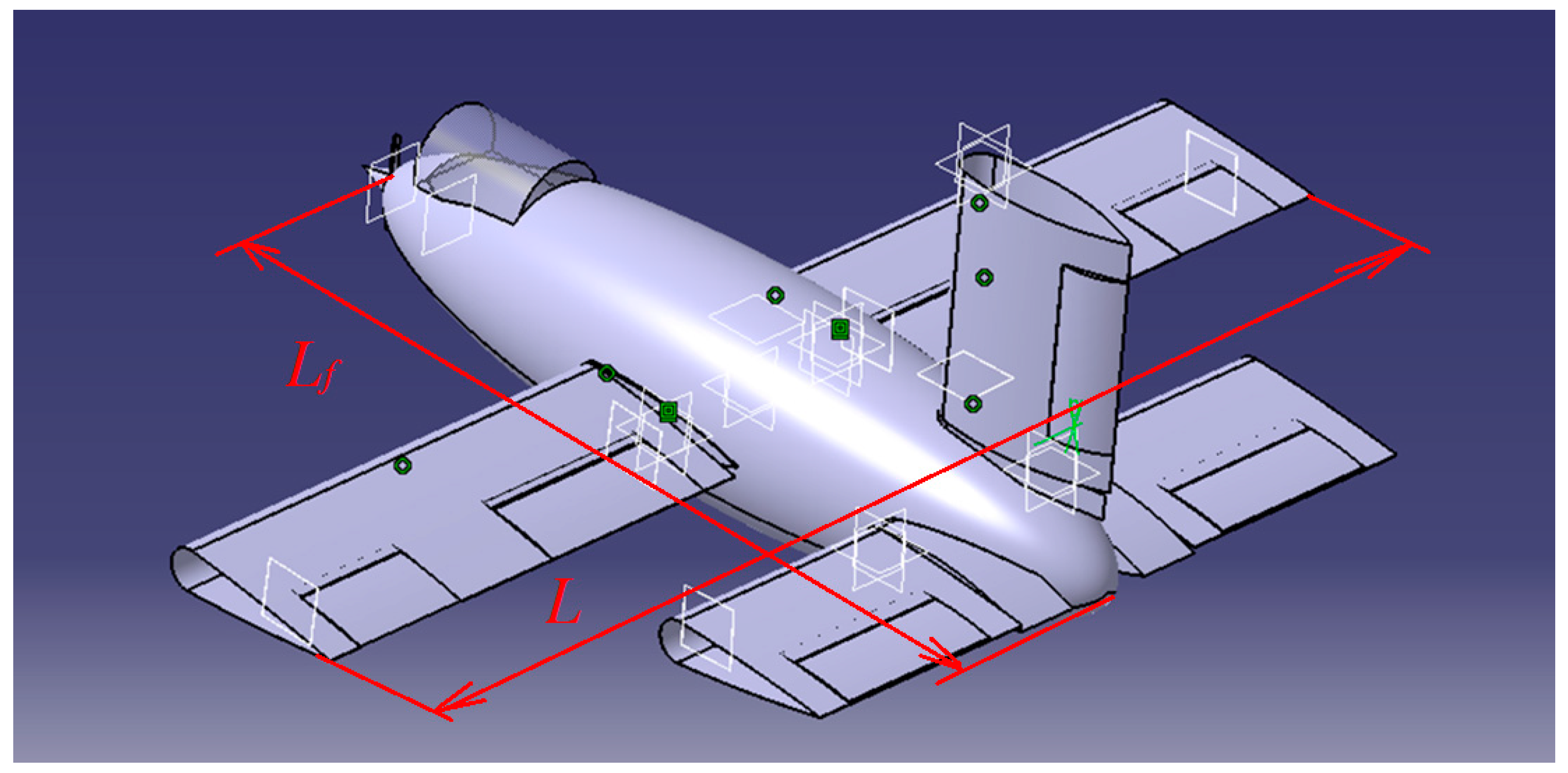
The main components of this light aircraft variant are the propeller helmet, propeller, cockpit, plane fuselage, a left wing with symmetrical profile, a right wing with symmetrical profile, ailerons (one on each wing) with symmetrical profile, flaps (one on each wing) with symmetrical profile, the depth on the horizontal tail, the left horizontal tail, the right horizontal tail, the direction on the vertical tail, the vertical tail. The newly designed light aircraft, named I.-M.G., shown in
Figure 1, has a maximum take-off weight of 900 Kg, and the cruising speed is 470 km per hour, and the maximum flight ceiling is 5.000 m.
In determining the aerodynamic shape and design dimensions of the light aircraft, the optimal design of the aircraft is considered, easily taking into account the parameters influencing the aerodynamic shape of the fuselage and the wing, as well as the systems and mechanisms of the flap and aileron that are mounted in these areas (
Figure 1).
Figure 2 shows a wing with a symmetric profile equipped with a flap and an aileron with a symmetrical profile each. They can be made of duralumin or aluminum.
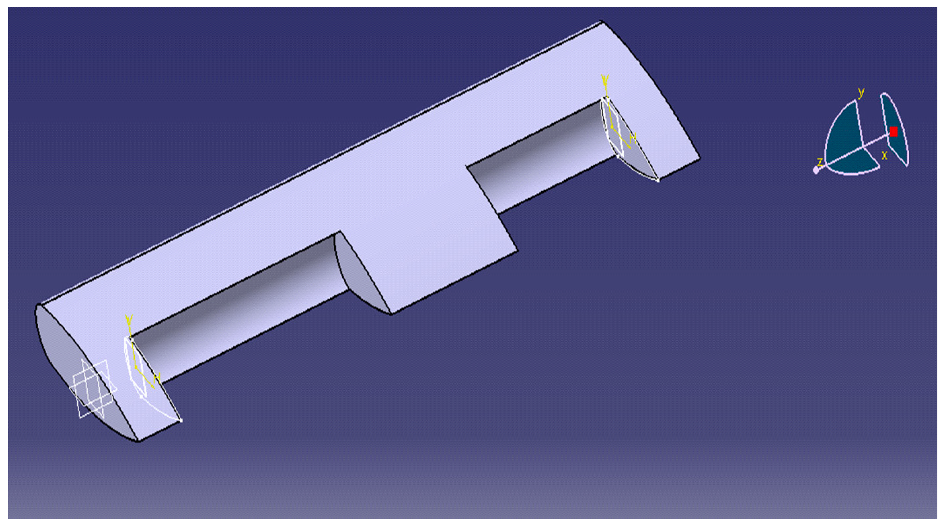
Figure 3 presents the structure of the wing with a symmetrical profile unequipped with flap and aileron.
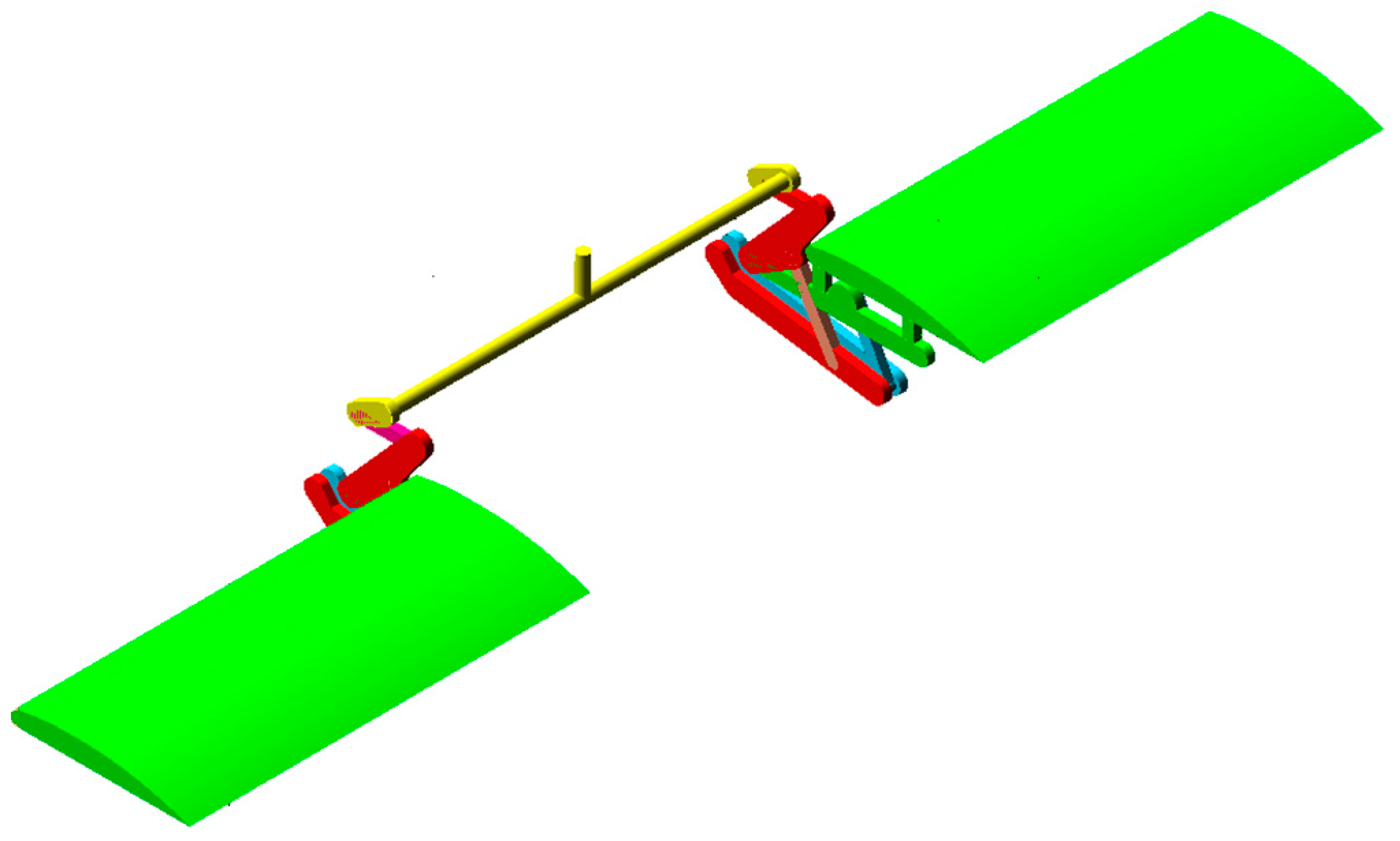
The control mechanism of the voles of a light aircraft, shown in
Figure 4, transmits the rotational motion from a valve lever 1 (1—leading element being the input into the mechanism), to a torsion tube 2, to the kinematic drive elements 3, to the kinematic actuators 4, to the complex connecting bodies 5, which transmit the rotational motion, on the one hand, to the non-snake-board curvature flaps 6, and, on the other hand, the kinematic connecting elements 9 transmit the movement between the complex connecting bodies 5 and the oscillating arms 10.
Elements 7 finally transmit the movement from the oscillating arms 10 to the 6th of the frictionless curvature for the escape board, thus transmitting the rotational movement, amplifying the force, and transmitting the mechanical power from lever 1 to the non-snake-board curvature flaps 6 (final driven elements set in motion with elements 1–10), with the aim of achieving larger gears corresponding to a high-performance flight regime characteristic of these aircraft and allowing take-off and landing over a short distance and in a short time.
The kinematic connecting elements (9, 8) are arranged at an angle with values between (0°… 90°) to the complex connecting bodies 5 and the oscillating arms 10, respectively, to the non-snake-board curvature flaps 6 and the oscillating arms 10. When operating the 1 control valve, the rotational movement is transmitted to a torsion tube 2, in solidarity with the kinematic drive elements 3 articulated at the base by the rotational couplings of A and A1 (which is the base, A and A1) and further to the kinematic actuators 4 by the rotation couplings of B and B1.
From the kinematic actuators 4, 16, the movement is transmitted to the kinematic actuator 5 through the rotational couplings in E and E1, the kinematic actuator 5 elements being connected to the bases by the rotational couplings in C and C1. These five bodies have three links (rotation couplings E, F, G, E1, F1, G1, respectively) and bases C and C1, respectively. The rotational couplings in F and F1 provide the connection between bodies 5 and bodies 9, and the rotation couplings in G and G1 provide the connection with the output bodies 6 (the endless curvature of the escape board, the asymmetric profile flap).
From bodies 5 via rotational couplings F and F1, the rotational movement is transmitted to bodies 10 and 20 by means of the rotational couplings J and J1, and from the 10 in rotational bodies of H and H1, the movement is transmitted to bodies 8, and then through the rotational couplings I and I1 to the non-snake-board curvature flaps 6 (6—output body = final driven element). Bodies 10 have a base connection through the rotational couplings in D and D1. This flap control mechanism of the new I.-M.G. light aircraft allows the volts to be braced up to a maximum of 55°.
In
Figure 5 and
Figure 6, the proposed optimized solution for the command system and the kinematical model of the mechanism are presented.
4. Optimization, Using Finite Element Model, of Wing and Flap
The method of finite elements is used as a need to study the state of deformations and stresses in the structure of the light aircraft named I.-M.G. The wing structure is analyzed using the CATIA computer-aided engineering (CAE) FEA software [
34].
The properties of the material are diversified according to the type of element and the type of problem to analyze. The mechanical characteristics of the material/materials used are defined. For the analysis of elastic structures, restrictions are necessary on the movements of translation and rotation with known values. To analyze the elastic mechanical structures, the loading of the model is carried out by inserting concentrated forces in knots and/or normal pressures in the centers of the faces of the finished elements or moments.
Figure 8 shows the 3D model of the wing with a symmetrical profile realized from duralumin. The introduction of the values of the material characteristics necessary for the analysis with finite elements is done using the material library of the CATIA software, from which the metallic material from duralumin is chosen, with the following characteristics: Young’s modulus = 7.31 × 10
10 N/m
2, Poisson ratio = 0.33, density = 2790 kg/m
3.
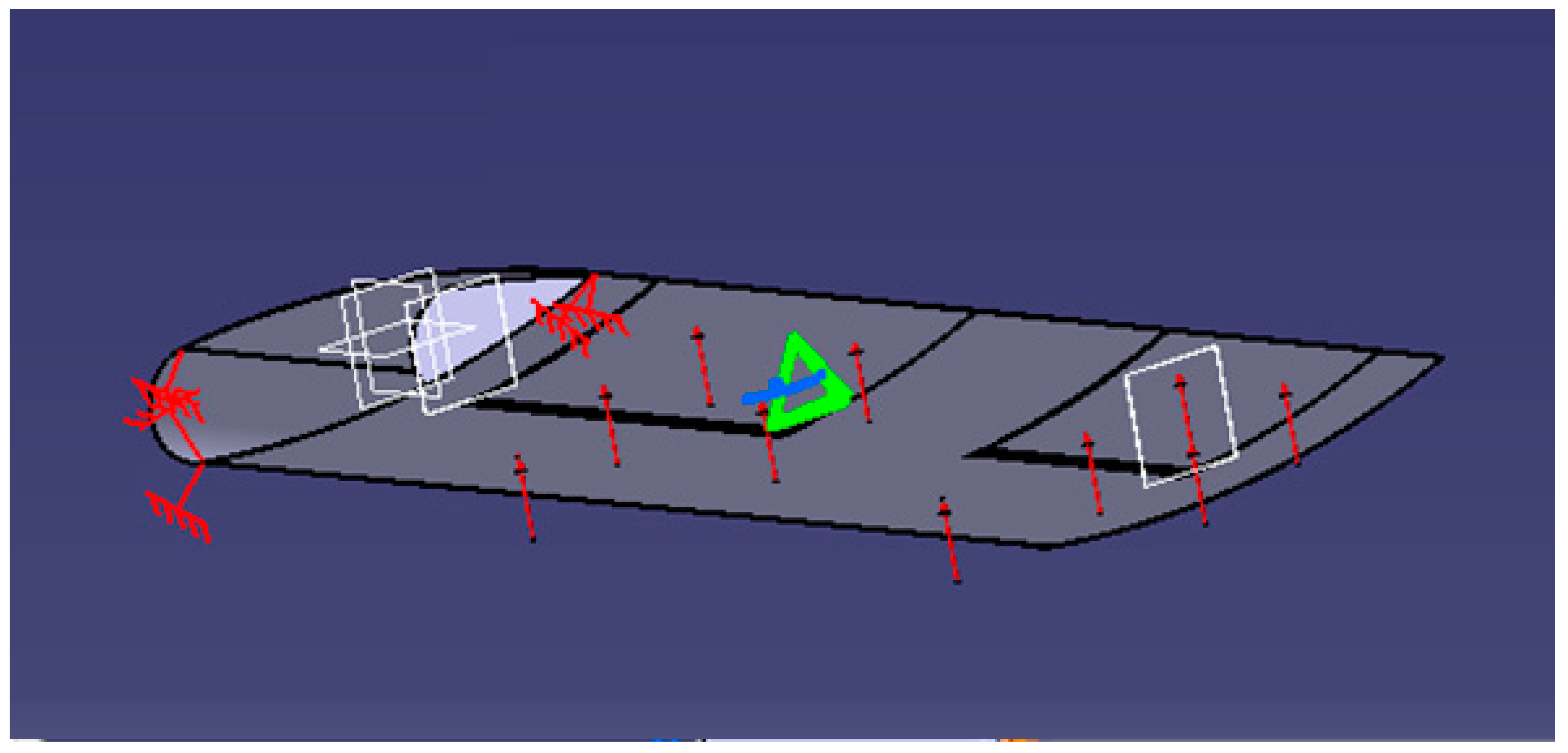
To generate the model, the finite element method is performed, which involves the static analysis of the structure under conditions of imposed constraints and independent time loads. The link with the base imposed on the model is defined by canceling the 6 degrees of possible freedom associated with the lateral surface of the wing (
Figure 9) [
22].
The loading of the model is a uniform pressure after the Y-axis on the face of the wing. The model solution is offered by soft. The displacement field of the wing with a symmetrical profile from duralumin is presented in
Figure 9, the maxim displacement being 9.72 mm.
The introduction of the values of the material characteristics necessary for the analysis with finite elements is done using the material library of the CATIA software, from which the metallic material from aluminum is chosen, with the following characteristics: Young’s modulus = 7.0 × 10¹⁰ N/m2, Poisson ratio = 0.346, and density = 2710 kg/m3.
The finite element method is performed to generate the model, involving the static analysis of the structure under conditions of imposed constraints and independent time loads. The liaisons with the base imposed on the model are defined by canceling the 6 degrees of possible freedom associated with the lateral surface of the wing (
Figure 10).
For the flap, the material characteristics of duralumin and aluminum are defined, and the structure is analyzed with finite elements to obtain the Von Misses field of deformations and stresses. The aim is to see the influence of the material on the deformations appearing in the structure of the flap. The mechanical characteristics of aluminum and duralumin are presented in
Table 2. It can be observed that the elasticity module for duralumin is higher than the elasticity module for aluminum, and the Poisson’s coefficient for duralumin is lower than the Poisson’s coefficient for aluminum.
Figure 11 shows the symmetric profile, which can be made by aluminum and which has relief holes that also have a functional role, through which the rods of the control mechanisms and the 3D model of the flap with symmetric profile from duralumin are passed. The introduction of the values of the material characteristics necessary for the analysis with finite elements is done using the material library of the CATIA software. Boundary conditions are presented in
Figure 12. To generate the model, the finite element method is performed, which involves the static analysis of the structure under conditions of imposed constraints and independent time loads.
The displacement field is calculated, the maxim displacement being 0.106 mm. The results of Equivalent Von Misses stress is visualized in
Figure 13, the maxim value being 2.63 × 10
6 N/m
2.
The link with the base imposed by the model is defined by canceling the 6 degrees of possible freedom associated with the lateral surface of the flap (
Figure 14). The loading of the model is a uniform pressure, after Y-direction, on the face of a wing made from aluminum.
The displacement field in the flap with the symmetric aluminum profile is presented in
Figure 15. The maxim displacement is 0.011 mm to the extremity free of the flap from aluminum.
Table 3 presents the results of finite element analysis for the wing with a symmetric profile.
Table 4 shows the results of finite element analysis for the flap with a symmetric profile.
Equivalent Von Misses stress in the flap with the symmetric aluminum profile is presented in
Figure 16, the maxim value being 2.63 × 10
6 N/m
2.
5. Discussions
The modern design process is a complex process that involves, among other things, the use of modeling methods and analysis based on the use of high-performance software. The finite element method offers solutions to the problems to identify the fields of variation in stresses and deformations. Field identification problems provide a spatial distribution of dependent variables, mathematical modeling of distributions, and dependencies being achieved by differential equations and expressions that contain integrals. CAD modeling of the I.-M.G. light aircraft and finite element analysis are done with the Catia V5 software using the Part Design module that allows the creation of the 3D model of pieces and the application of material characteristics specific to the material chosen for the creation of the pieces, features existing in the material library of the program or by introducing in the program the material characteristics specific to the material of the piece created.
After solid modeling in the CATIA Part Design module, the piece is considered to have a material (aluminum, duralumin), with physical properties, important during the analysis. These values are indicated by default by the CATIA program after selecting the piece in the specification tree and choosing the material “Aluminum/Duralumin” in the “Library” dialog window.
For the finite element analysis of the I.-M.G. light aircraft, the Catia V5 R21 software is used with the CATIA Generative Structural Analysis Module.
From the FEM analysis of the symmetrical profile wing of I.-M.G. aircraft loaded with a force, uniformly distributed and analyzed in two situations (duralumin, aluminum), it is apparent that the maximum deformation occurs in the duralumin wing. From the FEM analysis of the symmetrical profile wing and for the asymmetric profile wing loaded each with force, uniformly distributed, and analyzed in two situations (duralumin, aluminum), it is apparent that the deformation is minimal in the case of the asymmetric profile wing.
The advantages of this mechanism consist of a simple realization, easy maintenance, low-cost price but also the achievement of excellent performances for the studied plane. For this reason, it becomes important to study the compatibility of this type of mechanism with the structure of the studied aircraft. From all the results presented above, this compatibility, from the point of view of strength, is ensured.
6. Conclusions
The ever-increasing complexity of the products leads to some difficulties in design and manufacture. There are several solutions to this feature of modern production—the most used being the realization of new tools and technologies to support the approach of the project without significantly affecting the time of realization or the quality obtained.
Thus, improvements are imposed in the processes of design, calculation and optimization, simulation of manufacturing, or in the way of information management. Between all this, the assisted design presents a decisive link.
Reducing the duration of the product production cycle is possible when the design, manufacture, and finite element method are increasingly integrated.
CATIA allows the design of parts and assemblies directly in three dimensions, without first drawing the plates in representation (two-dimensional). Note that calculations can be made, which can be of great help to the engineer who wants to hold a single platform for CAD-CAE-CAM domains.
On the I.-M.G. light aircraft, a static analysis is carried out, with uniformly distributed forces, after the state of tensions and deformations in the analyzed parts is obtained. The I.-M.G. Light Sport Aircraft is designed with the median wing with a rectangular section, with a symmetrical profile. The wing is equipped with a flap and an aileron. The median wing is advantageous in terms of interaction with the fuselage. By increasing the length of the wings, the length of the flaps is also increased, which increases the lift during the take-off and landing of the aircraft slightly. The proposed I.-M.G. lightweight aircraft is designed by using original component elements like shape and size to improve the aerodynamics of the aircraft and its stability as follows: rectangular-shaped median wings and with an asymmetrical profile in its section so that the profile string forms an angle with the forward direction, of a range to a value greater than the fuselage length, L = (1.1...1.3) ∗ Lf, and implicitly increasing the surface of the flaps, which may allow the airplane to glide in critical flight situations when the engine is no longer running or when needed for fuel economy, allowing the aircraft to behave easily and like a plane, the central plane of the fuselage, the propeller helmet, the previous fuselage (hoods), the propellers and the handles of curvature without a run-out board (one on each wing), the cabin in which the crew sits, the depth, drift, direction, rear fuselage, stabilizer, and the 2nd section of the central fuselage. By mounting the flaps on the wings, the landings are smooth, and the plane does not hit the ground. The designed constructive solution of the flaps control mechanism for the new I.-M.G. light aircraft allows the steering to be braced up to a maximum of 55°, this value being superior to the classic solutions of mechanisms with flaps that poach up to a maximum of 45°. The finite element analysis of the flap and wing offers us a convenient solution with real maneuverability advantages.
A comparison of the stress and strain fields that occur in the aircraft structure when equipped with the new type of control mechanism, with the stress field that occurs when equipped with current mechanisms [
35], shows that these fields are admissible from the point of view of strength. So the proposed mechanism is compatible with the structure analyzed in the paper, and the calculated stress is lower than the limit stress.


 and
and 


