Article

Blind Color Image Watermarking Using Fan Beam Transform and QR Decomposition

1
Department of Computer Science and Engineering, Chittagong University of Engineering and Technology (CUET), Chattogram 4349, Bangladesh
2
Graduate School of Science and Engineering, Saitama University, Saitama 338-8570, Japan
*
Author to whom correspondence should be addressed.
Symmetry 2020, 12(3), 486; https://doi.org/10.3390/sym12030486
Submission received: 10 February 2020 / Revised: 8 March 2020 / Accepted: 10 March 2020 / Published: 23 March 2020

Abstract

:
Digital watermarking has been utilized effectively for copyright protection of multimedia contents. This paper suggests a blind symmetric watermarking algorithm using fan beam transform (FBT) and QR decomposition (QRD) for color images. At first, the original image is transferred from RGB to L*a*b* color model and FBT is applied to b* component. Then the b*component of the original image is split into m × m non-overlapping blocks and QRD is conducted to each block. Watermark data is placed into the selected coefficient of the upper triangular matrix using a new embedding function. Simulation results suggest that the presented algorithm is extremely robust against numerous attacks, and also yields watermarked images with high quality. Furthermore, it represents more excellent performance compared with the recent state-of-the-art algorithms for robustness and imperceptibility. The normalized correlation (NC) of the proposed algorithm varies from 0.8252 to 1, the peak signal-to-noise ratio (PSNR) varies from 54.1854 to 54.1892, and structural similarity (SSIM) varies from 0.9285 to 0.9696, respectively. In contrast, the NC of the recent state-of-the-art algorithms varies from 0.5193 to 1, PSNR varies from 38.5471 to 52.64, and SSIM varies from 0.9311 to 0.9663, respectively.

1. Introduction

Because of the latest developments of the internet, copyright protection of digital contents (video, image, audio, and text) has become progressively significant. Digital watermarking is a method which can attain this target successfully. Recently, many algorithms have been published in order to yield imperceptible and robust watermarks. A rigorous survey on digital watermarking was presented in [1,2,3]. In terms of the processing domain, the existing algorithms are mainly separated into two classes: spatial domain and transform domain algorithms. Spatial domain algorithms are straightforward to perform but less robust to numerous attacks [4]. At the same time, transform domain algorithms [5,6,7,8,9,10,11,12,13,14,15,16,17,18,19,20,21] are robust against diverse attacks.
Ali Al-Haj [5] introduced a non-blind image watermarking algorithm using discrete wavelet transform (DWT) and discrete cosine transform (DCT). It shows good results for imperceptibility; however, robustness result against compression and cropping attack is quite low. D. Dejey et al. [6] introduced a non-blind watermarking technique that employs DWT and fan beam transform (FBT) jointly. It provides good imperceptible watermarked sound, but it has low robustness against cropping and rotation attack. Shuai et al. [7] suggested a non-blind method using fractal encoding and DCT. It also shows good results for imperceptibility; however, the robustness of this method is evaluated for only three attacks. Moreover, it has low robustness against Gaussian noise attack. In [8], the authors suggested a blind method using redundant DWT (RDWT) and DCT, where a binary image is utilized as watermark. This method is highly imperceptible; however, it has low robustness against mean and median filtering attacks. The authors of [9] introduced a non-blind watermarking method using DCT and DWT. This method produces good imperceptible watermarked sounds; however, it has low robustness against salt-and-pepper noise, speckle noise, and rotation attacks. Hamidi et al. [10] presented a blind image watermarking method using discrete Fourier transform (DFT) and DCT. This method provides good results for imperceptibility; however, the robustness of this method was tested against very few attacks such as salt and pepper noise, JPEG compression, histogram equalization, Gaussian noise, etc. A non-blind improved watermarking algorithm was suggested by Ahmad et al. [11], whose imperceptibility is high; but, the robustness to some attacks is quite low. Mohashin et al. [12] proposed a blind method that utilizes discrete Hilbert transform (DHT) and polar decomposition (PD). This method is highly imperceptible; but this algorithm also shows low robustness for some attacks.
Zhang et al. [13] proposed a blind method in the DCT domain using bimodal structure and iterative selection process. It has good robustness against attacks; however, the peak signal-to-noise ratio (PSNR) of this technique is little low. Roy et al. [14] suggested a blind watermarking technique using DCT, where the watermark is placed in the middle frequency region of the host image. This method shows high robustness against numerous attacks; but, the PSNR of this method is not quite high. Q. Su et al. [15] introduced a blind algorithm using QR decomposition (QRD) where watermark is placed into upper triangular matrix. The robustness result of this method is quite high against attack; but this algorithm has low imperceptibility. In [16], a blind algorithm was presented that employs singular value decomposition (SVD), where the watermark is placed into U matrix. The imperceptibility result of this method is quite high; but it shows low robustness against rotation attack. L. Chih-Chin et al. [17] presented a non-blind algorithm for gray scale image that employs DWT and SVD. G. Bhatnagar et al. [18] suggested a semi-blind method using DWT and SVD. These methods are robust against attacks; however, these methods have low imperceptibility results. Q. Su et al. [19] proposed a blind method using Schur decomposition (SD). It provides high robustness against numerous attacks; however, the imperceptibility result of this method is not quite high. In [20], the authors suggested a blind algorithm using LU decomposition (LUD), where the watermark information is embedded into the first elements of both second and third rows of the lower triangular matrix. This method is robust against attacks; however, it has low imperceptibility. Khanam et al. [21] suggested a blind technique based on fast Walsh–Hadamard transform (FWHT), SVD, key mapping, and coefficient ordering. It has high robustness against numerous attacks but its imperceptibility result is little low.
From the above discussion, it is concluded that some algorithms have low robustness, whereas some algorithms have less imperceptible. Moreover, some algorithms are non-blind and semi blind. To overcome these drawbacks, here, a symmetric watermarking approach is presented that employs FBT and QRD. To the best of our information, this is the first watermarking algorithm that uses FBT and QRD jointly for color image. The key contribution of our suggested algorithm incorporate (i) it employs the FBT, QRD, and quantization jointly; (ii) watermark data is placed into the first row fourth column of the upper triangular matrix acquired from the FBT coefficients of b* component of original image employing an insertion operation; (iii) the process of detecting watermark is blind; and (iv) it yields a significant trade-off for imperceptibility and robustness. Experimental results suggest that the introduced algorithm shows significance resistance against diverse attacks. Besides, it yields watermarked images with high quality. Furthermore, it shows more excellent result in comparison with the recent state-of-the-art algorithms [19,20,21] for imperceptibility and robustness. It is because watermark information is inserted into the first row fourth column of the upper triangular matrix acquired from the FBT coefficients of b* component of original image using a new embedding equation.

2. Background Information

2.1. Fan Beam Transform

In FBT, the projection of any function f(x,y) is represented as a set of line integrals. Here, data may be built by radiating from multiple and single sources. Projection of an image may be calculated at any angle θ. In fan beam geometry, there are n sensors and one emitter. Consider f as a real integral function on the plane R2. Also consider a point S as source and v θ as unit vector in a direction θ ∈ [0, 2π] on the plane. Then, FBT, denoted by F, applies on function f as follows:
[ F f ] ( S , θ ) = 0 f ( S + u . v θ ) d u
The equation introduced in Equation (1) is known the fan beam projection of f carried out from the point S with direction θ. The fan beam projection calculates the projection data known as sinogram [4].

2.2. QR Decomposition

The QRD of a matrix A with size m × m can be defined as follows:
[ Q , R ] = q r ( A )
where Q represents an unitary matrix with size m × m and R represents an upper triangular matrix with size m × m such that A = Q × R [15].

3. Proposed Watermarking Algorithm

Consider A = {a(k, l), 1 ≤ kM, 1 ≤ lM} is the original image and W = {w(i, j), 1 ≤ iN, 1 ≤ jN} is the watermark image that will be placed into the original image.

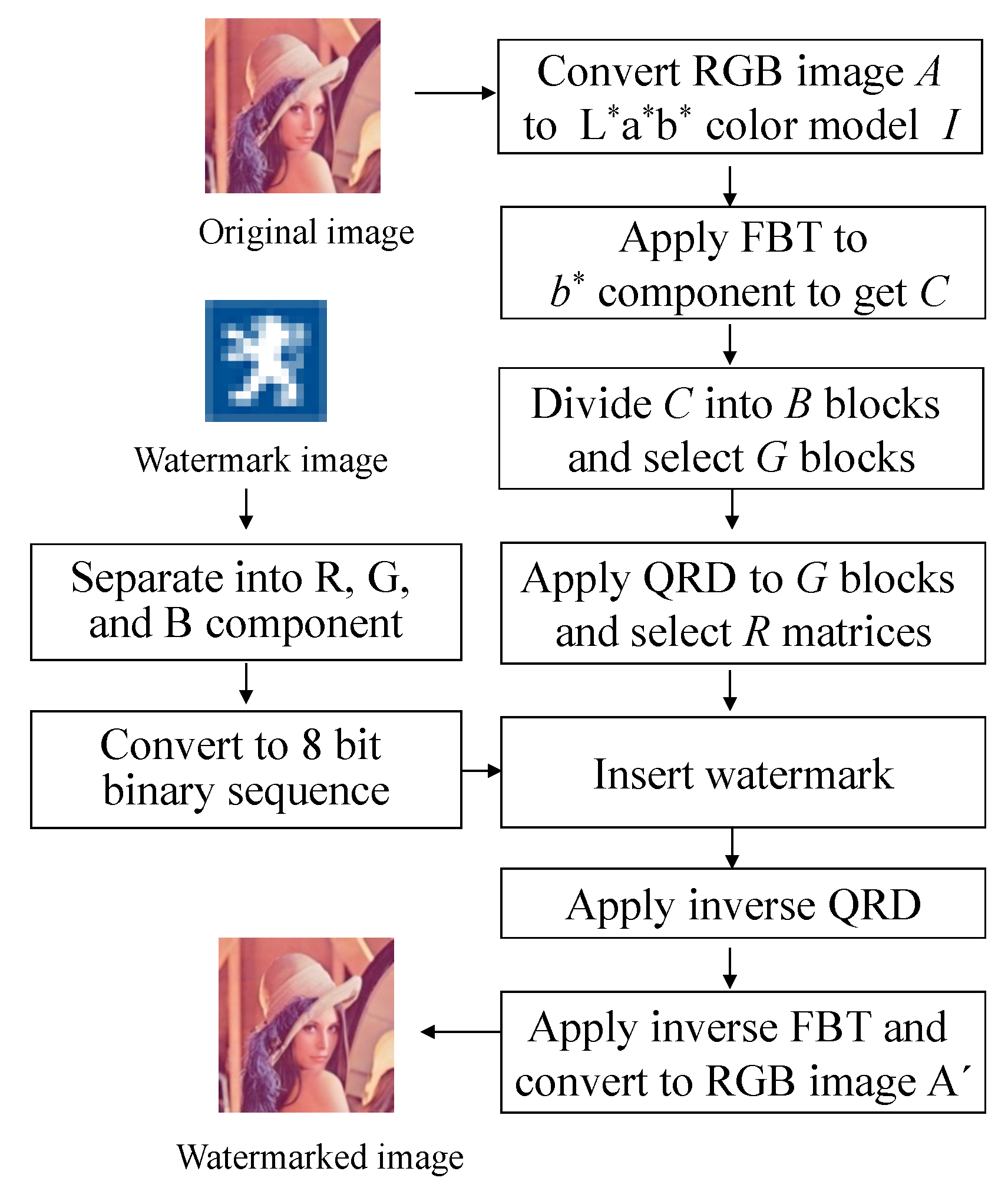
3.1. Watermark Embedding Process

The technique of inserting watermark is shown in Figure 1 and discussed below:
Step 1: At first, the color watermark image W is separated into R, G and B components.
Step 2: Each pixel value of R, G, and B components is transformed into 8-bit binary sequence. Finally, watermark sequence Y is obtained by concatenating all 8-bit binary sequences of R, G, and B components of watermark image W, where Y = { y ( p ) ,   1 p N × N } .
Step 3: The original image A is transferred from RGB to L*a*b* color model which is represented by I.
Step 4: The b* component of L*a*b* color model I is selected, because human visual system is less sensitive to b* component. Then, FBT is applied to b* component to obtain FBT coefficients which are represented by C with size U × V.
Step 5: The FBT coefficients C which are also known as sinogram, are separated into r non-overlapping small blocks B with size m × m, where B = { B q , 1 q r } . The value of r and m depends on C, i.e., as the size of C increases, the value of r and m also increases and vice versa. Therefore, C = r × m × m.
Step 6: Determinant of each block Bq is calculated which is represented by
E q = | B q |
where |   | represents the determinant operation and Eq is the determinant of each block Bq. Then n blocks with larger determinants are selected, where E s e l e c t = { E s , 1 s n } represents the determinant of corresponding selected blocks represented by G = { G s , 1 s n } .
Step 7: QRD is conducted to the selected blocks G = { G s , 1 s n } to attain the   Q = { Q s , 1 s n } and R = { R s , 1 s n } matrices. Each matrix Rs is selected for inserting watermark.
Step 8: The watermark bit is placed into the first row fourth column element r s ; ( 1 , 4 ) of each matrix Rs. Let
T1 = −0.5Δ, T2 = 0.5Δ
where T1 and T2 are magnitudes and Δ is the quantization step size. The element r s ; ( 1 , 4 ) is selected because it is likely to be greater than those of the elements in other rows which allows a greater modified range. Moreover, this element has an indirect effect on the first row fourth column element of each block.
Step 9: (i) When watermark bit is 0, the following Equation (5) is used:
r s ; ( 1 , 4 ) = { r s ; ( 1 , 4 ) × c e i l ( T 1 / Δ ) ( 1 / β ) i f ( r s ; ( 1 , 4 ) + T 1 ) > T 1 r s ; ( 1 , 4 ) o t h e r w i s e
(ii) When watermark bit is 1, the following Equation (6) is used:
r s ; ( 1 , 4 ) = { r s ; ( 1 , 4 ) × f l o o r ( T 2 / Δ ) + ( 1 / β ) i f ( r s ; ( 1 , 4 ) + T 2 ) < T 2 r s ; ( 1 , 4 ) o t h e r w i s e
where r s ; ( 1 , 4 ) is the modified element and β is the embedding strength.
Step 10: Reinsert each modified element r s ; ( 1 , 4 ) to obtain the each modified matrix R s and inverse QRD is performed to receive the modified block G s .
Step 11: Each modified block G s is replaced to original block. Then all modified and the rest unmodified blocks are concatenated to get the modified FBT coefficients C’ and inverse FBT is applied on it to receive the modified b’* component.
Step 12: Finally, the modified L*a*b’* color model I is transformed into RGB color model to obtain the watermarked image A.
The pseudo code of the watermark inserting procedure is illustrated in Algorithm 1.
Algorithm 1: Watermark Inserting Procedure
Declaring variables:
A: original RGB image
I : converted L*a*b* image
Y: watermark sequence
C: FBT coefficients
B: block with size m × m
G: selected block with size m × m
Q: unitary matrix with size m × m
R: upper triangular matrix with size of m × m
r s ; ( 1 , 4 ) = selected element for embedding watermark
FBT and QRD: transformation and decomposition used in the algorithm
Watermark Embedding Procedure:
Read the host image and watermark image
A.bmp (original image with size 512 × 512)
W.bmp (color watermark image with size of 16 × 16)
for i = 1: N
j = 1: N do
Separate W into R, G, and B components and convert them into binary sequence
end for
return the watermark sequence
for k = 1: M
l = 1: M do
A is transferred from RGB to L*a*b* color model
end for
Select b* channel and apply FBT to obtain C
for i = 1: r
Separate C into r blocks B
end for
Calculate determinant of each block B and select largest n blocks
for p = 1: N × N
Insert watermark using Equation (5) when y(p) = 0
Insert watermark using Equation (6) when y(p) = 1
end for
Perform inverse QRD
Perform IFBT to get modified channel b*
The modified L*a*b* color model is transformed into RGB color model
return watermarked image A

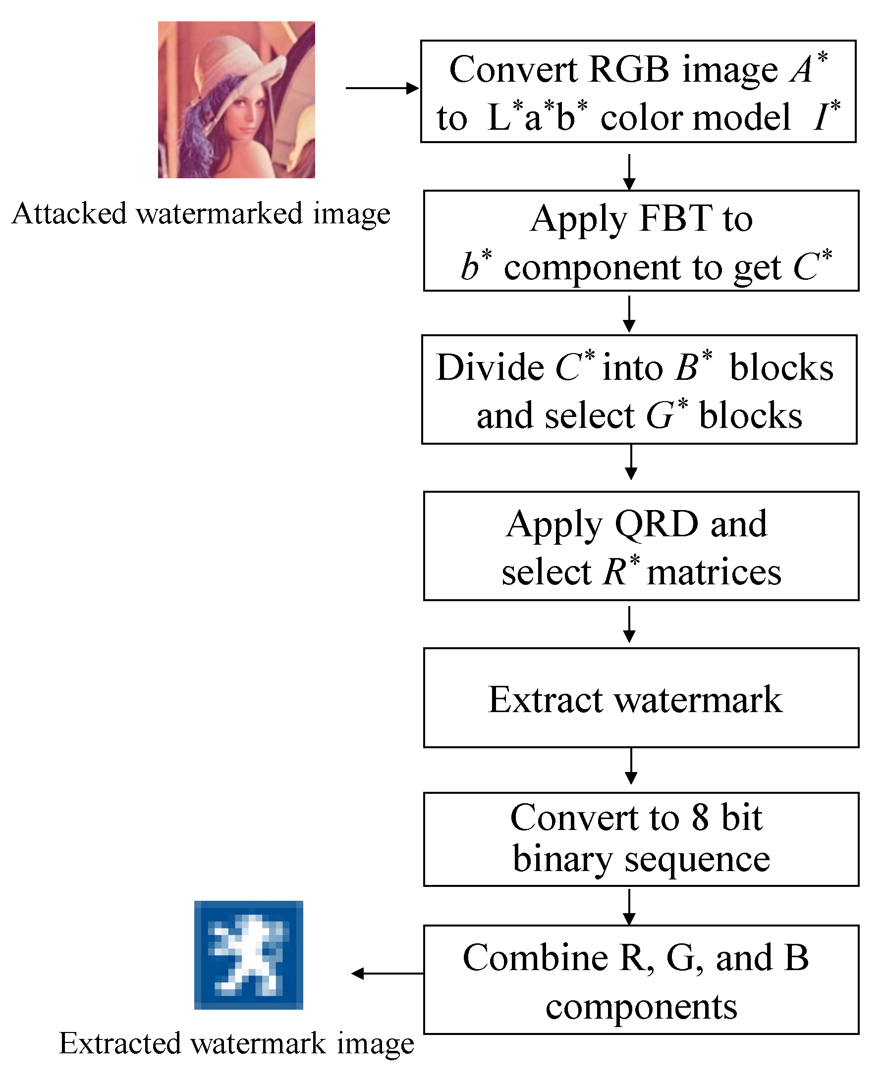
3.2. Watermark Detection Process

The technique of detecting the watermark is shown in Figure 2 and discussed below:
Step 1: Attacked watermarked image A* is transformed from RGB to L*a*b* color model I*. Then b* component is selected and FBT is applied on it to get FBT coefficients C*.
Step 2: FBT coefficients C* are then divided into m × m non-overlapping blocks B*.
Step 3: Determinant of each block B q with size m × m is calculated and n blocks with largest determinants are selected. The selected blocks are represented by G = { G s , 1 s n } .
Step 4: QRD is conducted to each of G to attain the matrices Q = { Q s , 1 s n } and R = { R s , 1 s n } .
Step 5: The watermark bit is extracted from the first row fourth column element r s ; ( 1 , 4 ) of each of R* matrices using the following equation
Y = { 0 i f   r s ; ( 1 , 4 ) 0 1 o t h e r w i s e
Step 6: The step 4 is repeated until extracting all watermark bits. These extracted bits are separated into 8-bits per group and the value of each group is converted into decimal value to get the R, G, B components.
Step 7: The watermark image can be found by combining the R, G, and B components.
The pseudo code of detecting the watermark is illustrated in Algorithm 2.
Algorithm 2: Watermark extracting procedure
Declaring variables:
A*: attacked watermarked RGB image
I*: attacked watermarked L*a*b* image
Y*: extracted watermark sequence
C*: modified FBT coefficients
B*: modified block with size m × m
G*: modified selected block with size m × m
Q*: modified unitary matrix with size m × m
R*: modified upper triangular matrix with size m × m
r s ; ( 1 , 4 ) = selected element for extracted watermark
FBT and QRD: transformation and decomposition used in the algorithm
Watermark extraction procedure:
Read the attacked watermarked image
A*.bmp (attacked watermark image with size of 512 × 512)
for k = 1: M
l = 1: M do
A* is transferred from RGB to L*a*b* color model
end for
Select b* channel and apply FBT to obtain C*
for i = 1: r
Separate C* into r blocks B*
end for
Calculate determinant of each block B* and select largest n blocks
for p = 1: N × N
Extract watermark using Equation (7)
end for
Separate the extracted bits into 8-bits per group
Convert each group into decimal value to get the R, G, B components
Combine the R, G, and B components to get the watermark image

3.3. Performance Assessment of Proposed Algorithm

To assess the imperceptibility (i) peak signal-to-noise ratio (PSNR) [19,20,21] and (ii) structural similarity (SSIM) [19,20,22] were considered. Normalized correlation (NC) is used to measure robustness of our proposed algorithm [19,20,21]. These are represented by the following equations:
P S N R = 10 log 10 ( 255 2 1 M M k = 1 M l = 1 M ( A ( k , l ) A ( k , l ) ) 2 )
S S I M = l ( A , A ) c ( A , A ) s ( A , A ) where l ( A , A ) = 2 μ A μ A + c 1 μ A 2 μ A 2 + c 1 , c ( A , A ) = 2 σ A σ A + c 2 σ A 2 σ A 2 + c 2 , s ( A , A ) = σ A σ A + c 3 σ A σ A + c 3 ,
N C ( W , W ) = i = 1 M j = 1 M w ( i , j ) w ( i , j ) i = 1 M j = 1 M w ( i , j ) w ( i , j ) i = 1 M j = 1 M w ( i , j ) w ( i , j )
where, A, A, W, W*, µ, σ indicate the original host image, watermarked host image, watermark image, watermark image after extraction, local mean, and standard deviation of the image, respectively.

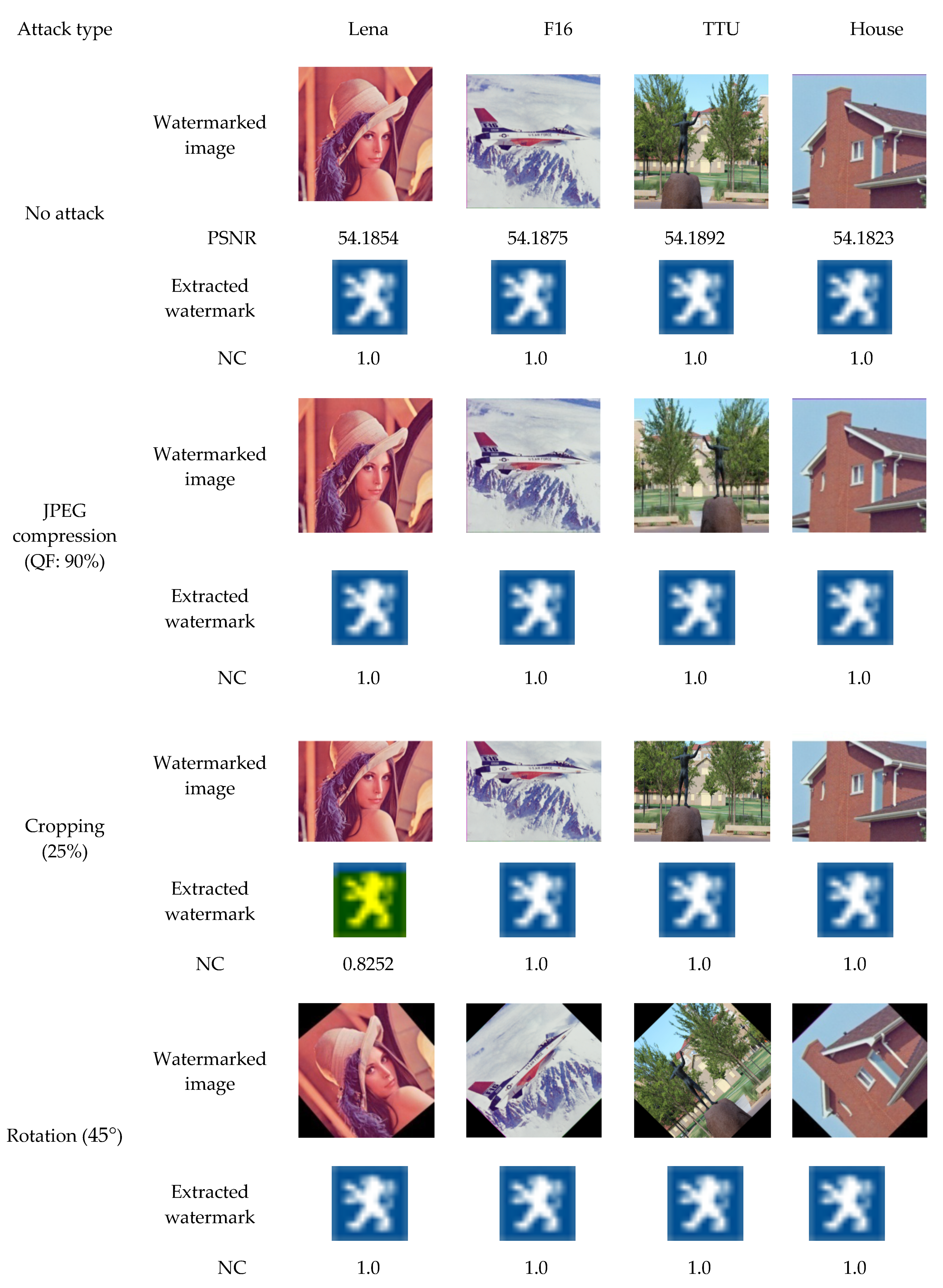
4. Simulation Results and Discussion

In this study, the results of our proposed algorithm are assessed for imperceptibility and robustness. Here, four 512 × 512 color images such as ‘Lena’, ‘F16’, ‘TTU’, and ‘House’ are used as host images which are given in Figure 3a–d. These images are collected from the USC SIPI image dataset [23]. The corresponding watermarked images produced by applying our suggested algorithm after embedding the watermark are also shown in Figure 3e–h. Moreover, the differences between the original and watermarked images are given in Figure 3i–l. One 16 × 16 color image is used as watermark image which is shown Figure 4. From Figure 3, we noticed that the watermarked and original images are perceptually similar.
The resolution of the fan beam projection image is 1208 × 360 for the host image. In other word, the resolution of the sonogram data is 1208 × 360. The projection image is divided into 4 × 4 block; therefore, 27,180 blocks are obtained. The determinant of each block is calculated. As the size of watermark image is 16 × 16, thus, we have 16 × 16 × 3 × 8=6144 bits to embed. For this reason, the selected value for n is 6144. In our proposed method, rotation increment is 1 degree, sensor spacing is 0.05 and sensor geometry is line sensor. In this study, in order to get good result, the chosen value for Δ, β, and m are 42, 10, and 4, respectively which are used as secret key K.
Table 1 illustrates an analysis between the suggested and various recent algorithms [19,20,21] for imperceptibility of various images. From this Table, we noticed that the PSNR and SSIM values of the suggested algorithm range from 54.1823 to 54.1823 and 0.9285 to 0.9696, respectively, whereas the PSNR and SSIM values of the recent methods range from 48.62 to 53.32 and 0.9321 to 0.9123, respectively indicating that the suggested algorithm has higher PSNR and SSIM than the recent advanced methods presented in [19,20,21]. This is because watermark data is placed into the first row fourth column of the matrix R attained from the FBT coefficients of b* component of original host image.
To compute the robustness, numerous attacks have been performed to watermarked images which are represented below:
  • JPEG compression: the watermarked images were compressed using JPEG compression (QF = 90);
  • Cropping: the watermarked images were cropped (25%) from the top;
  • Rotation attack: the watermarked images were rotated by 45° and the rotated images were re-rotated in a counter-clockwise for extraction;
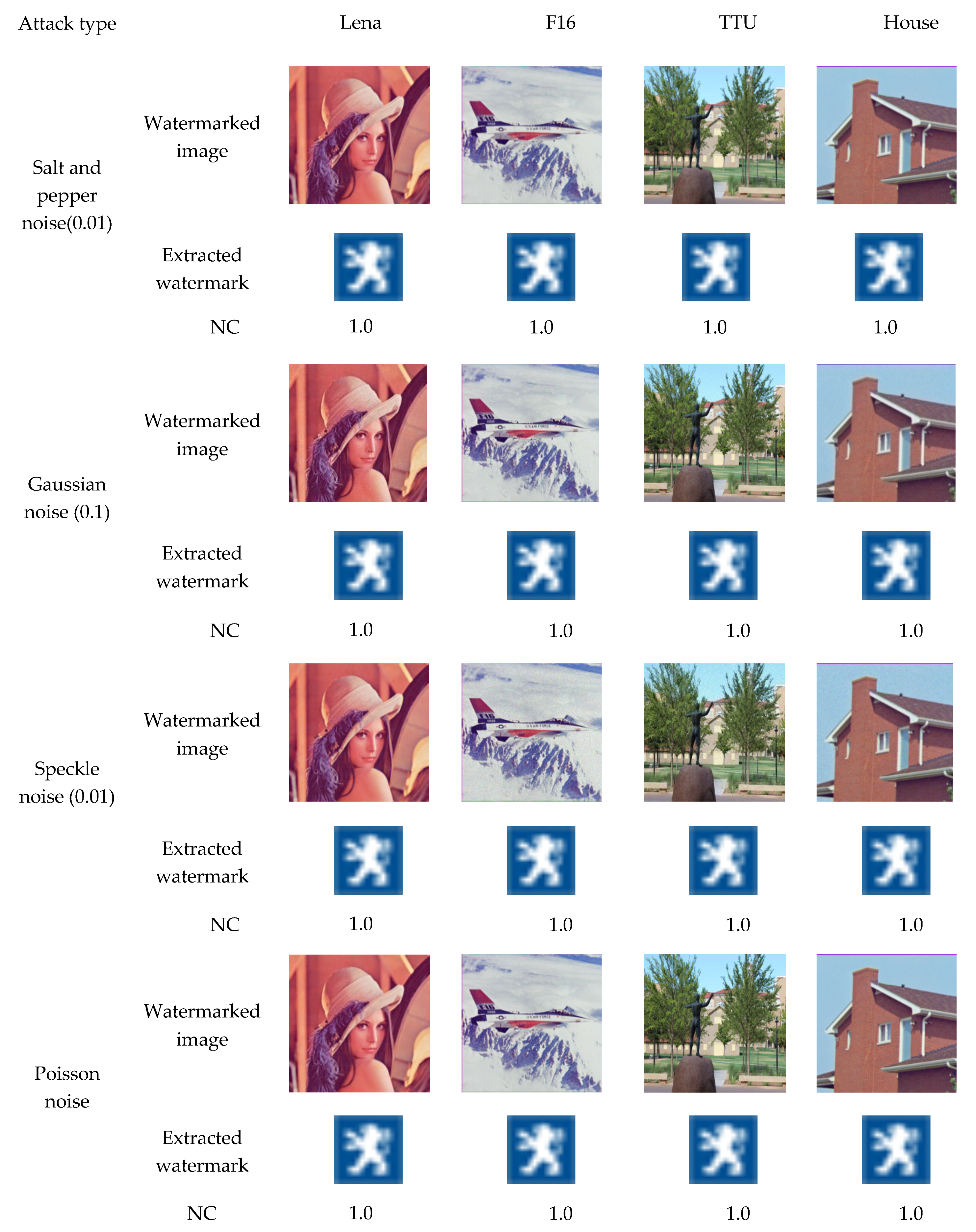
  • Gaussian noise: the watermarked images were attacked by Gaussian noise with variance 0.1;
  • Speckle noise: the watermarked images were attacked by speckle noise with variance 0.01;
  • Salt and pepper noise: Salt and pepper noise with variance 0.01 is performed to the watermarked images;
  • Poisson noise: the watermarked images were attacked by Poisson noise with scaling factor 1e12;
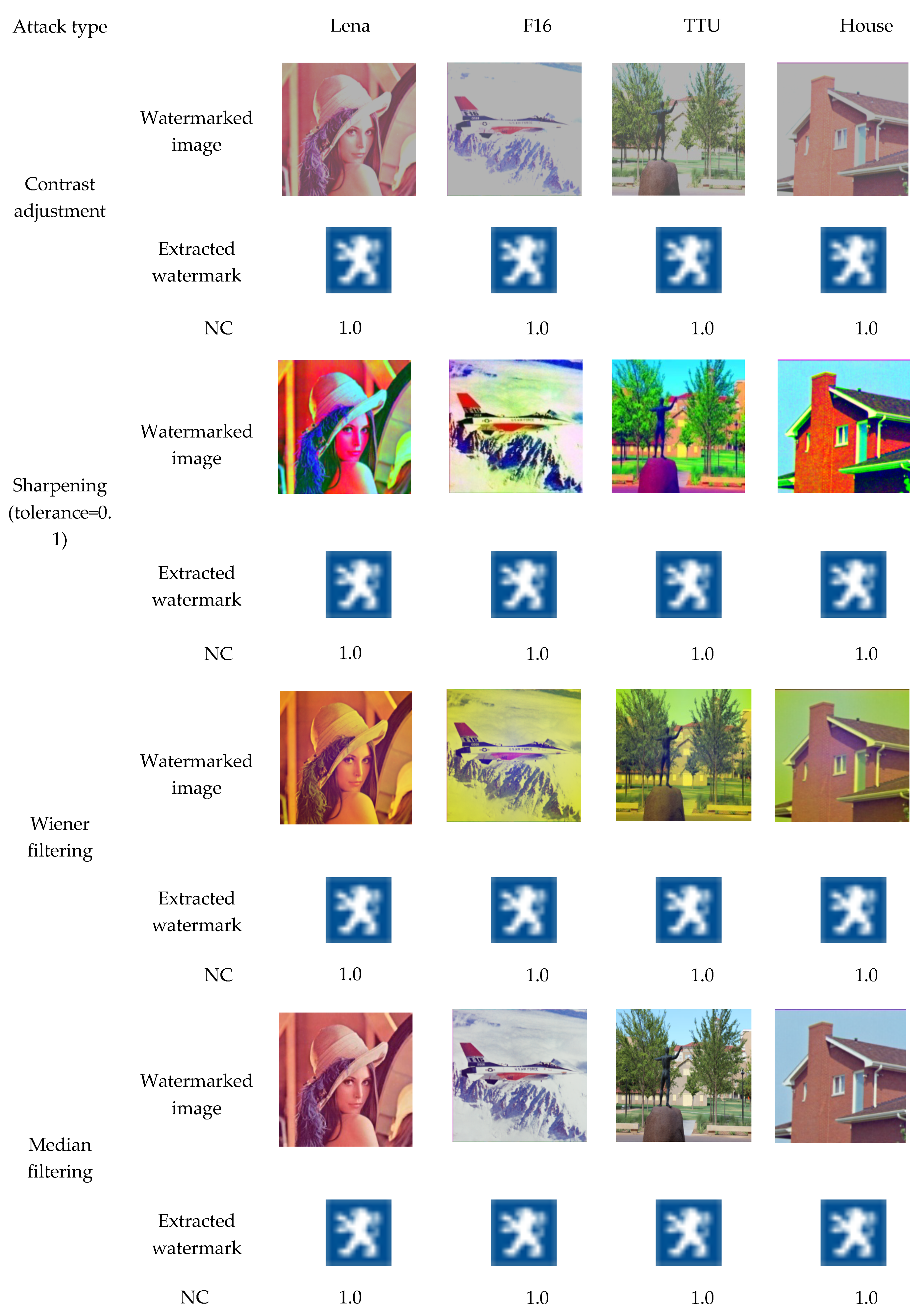
  • Contrast adjustment: the watermarked images were attacked by contrast adjustment;
  • Sharpening: the watermarked images were attacked by sharpening with tolerance 0.1;
  • Median filtering: the watermarked images were attacked by 3 × 3 median filter;
  • Wiener filtering: the watermarked images were attacked by 3 × 3 wiener filter.
Figure 5, Figure 6 and Figure 7 shows the NC, extracted watermark image and watermarked image when numerous attacks were conducted. We noticed that extracted watermark images and original watermark images are visually similar except cropping attack for ‘Lena’ image. We also noticed that the NCs of the presented algorithm are 1 against numerous attacks and NC against cropping attack is 0.8732 for ‘Lena’ image. It is because the b* component of the attacked watermarked ‘Lena’ image was affected more than that of the other attacked watermarked images. For this reason, the NC is little lower for attacked watermarked ‘Lena’ image against cropping attack compared to other images. From these results, we can say that the suggested algorithm has high robustness against various attacks.
Table 2 illustrates an analysis between the proposed with the recent state-of-the-art algorithms [19,20,21] for robustness. It is said that the NC of the proposed algorithm against numerous attacks is absolutely 1 except cropping attack for ‘Lena’ image; whereas the NC of the recent advanced algorithms [19,20] vary from 0.6482 to 0.9998, indicating that the NC values of the presented algorithm are significantly higher than that of state-of-the-art algorithms. From Table 2, it is also observed that the method [21] is highly robust against various attacks with key approach; however, it provides very low robustness against some attacks specially rotation, wiener filtering, and JPEG compression attack without key approach. Therefore, the proposed algorithm shows significantly higher robustness than the method without the key approach [21] and shows comparable robustness with the method with the key approach [21]. In other words, the suggested algorithm outperforms recent methods for robustness, because of inserting watermark into the first row fourth column of the matrix R acquired from the FBT coefficients of b* component of original image.

5. Conclusions

A blind symmetric watermarking algorithm was suggested in this paper using two transformation and decomposition techniques such as FBT and QRD that are used in image watermarking for the first time. The watermark has been inserted into the first row fourth column of the matrix R acquired from the FBT coefficients of b* component of original image using a new embedding equation. The experimental results suggested that the presented algorithm is not only robust against many attacks such as salt and pepper noise, Gaussian noise, rotation, JPEG compression, cropping, wiener filtering, median filtering, and sharpening etc., but also yield watermarked images with good quality. Furthermore, it outperforms state-of-the-art algorithms in respect of imperceptibility and robustness. These results verify that the presented algorithm can be effectively utilized for copyright protection of color image.

Author Contributions

All authors contributed equally to the conception of the idea, the design of experiments, the analysis and interpretation of results, and the writing and improvement of the manuscript. All authors have read and agreed to the published version of the manuscript.

Funding

This research received no external funding.

Conflicts of Interest

The authors declare no conflict of interest.

References

  1. Cox, I.J.; Miller, M.L. The first 50 years of electronic watermarking. EURASIP J. Adv. Signal Proces. 2002, 56, 126–132. [Google Scholar] [CrossRef] [Green Version]
  2. Tao, H.; Chongmin, L.; Zain, J.M.; Abdalla, A.N.T. Robust image watermarking theories and techniques: A review. J. Appl. Res. Technol. 2014, 12, 122–138. [Google Scholar] [CrossRef] [Green Version]
  3. Dhar, P.K.; Shimamura, T. Advances in Audio Watermarking Based on Singular Value Decomposition; Springer: Berlin, Germany, 2015; ISBN 978-3-319-14799-4. [Google Scholar]
  4. Celik, M.; Sharma, U.; Saber, G.E.; Tekalp, A.M. Hierarchical watermarking for secure image authentication with localization. IEEE Trans. Image Process. 2002, 11, 585–595. [Google Scholar] [CrossRef] [PubMed]
  5. Haj, A.A. Combined DWT-DCT digital image watermarking. J. Comput. Sci. 2007, 3, 740–746. [Google Scholar]
  6. Dejey, D.; Rajesh, R.S. Robust discrete wavelet–fan beam transforms-based color image watermarking. IET Image Process. 2011, 5, 315–322. [Google Scholar] [CrossRef]
  7. Shuai, L.; Zheng, P.; Houbing, S. Digital image watermarking method based on DCT and fractal encoding. IET Image Process. 2017, 11, 815–821. [Google Scholar]
  8. Roy, S.; Pal, A.K. A robust blind hybrid image watermarking scheme in RDWT-DCT domain using Arnold scrambling. Multimed. Tools Appl. 2017, 76, 3577–3616. [Google Scholar] [CrossRef]
  9. Abdulrahman, A.K.; Ozturk, S. A novel hybrid DCT and DWT based robust watermarking algorithm for color images. Multimed. Tools Appl. 2019, 78, 17027–17049. [Google Scholar] [CrossRef]
  10. Hamidi, M.; El Haziti, M.; Cherifi, H.; El Hassouni, M. Hybrid blind robust image watermarking technique based on DFT-DCT and Arnold transform. Multimed. Tools Appl. 2018, 77, 27181–27214. [Google Scholar] [CrossRef] [Green Version]
  11. Ahmad, A.M.; Ali, A.; Sameer, S. An improved SVD-based watermarking scheme for protecting rightful ownership. Signal Process. 2008, 88, 2158–2180. [Google Scholar]
  12. Mohashin, A.H.M.; Dhar, P.K.; Shimamura, T. Blind image watermarking based on discrete Hilbert transform and polar decomposition. In Proceedings of the 11th International Conference on Knowledge and Smart Technology (KST-2019), Phuket, Thailand, 23–26 January 2019; pp. 78–81. [Google Scholar]
  13. Li, J.; Zhang, C. Blind and robust watermarking scheme combining bimodal distribution structure with iterative selection method. Multimed. Tools Appl. 2019, 1–35. [Google Scholar] [CrossRef]
  14. Roy, S.; Pal, A.K. A blind DCT based color watermarking algorithm for embedding multiple watermarks. AEU Int. J. Electron. Commun. 2017, 72, 149–161. [Google Scholar] [CrossRef]
  15. Su, Q.; Niu, Y.; Wang, G.; Jia, S.; Yue, J. Color image blind watermarking scheme based on QR decomposition. Signal Process. 2014, 94, 219–235. [Google Scholar] [CrossRef]
  16. Su, Q.; Niu, Y.; Zou, H.; Liu, X. A blind dual color image watermarking based on singular value decomposition. Appl. Math. Comput. 2013, 219, 8455–8466. [Google Scholar] [CrossRef]
  17. Chih-Chin, L.; Cheng-Chih, T. Digital image watermarking using discrete wavelet transform and singular value decomposition. IEEE Trans. Instrum. Meas. 2010, 59, 3060–3063. [Google Scholar]
  18. Bhatnagar, G.; Raman, B. A new robust reference watermarking scheme based on DWT-SVD. Comput. Stand. Interfaces 2009, 31, 1002–1013. [Google Scholar] [CrossRef]
  19. Su, Q.; Yuan, Z.; Liu, D. An approximate schur decomposition-based spatial domain color image watermarking method. IEEE Access 2018, 7, 4358–4370. [Google Scholar] [CrossRef]
  20. Su, Q.; Wang, G.; Zhang, X.; Lv, G.; Chen, B. A new algorithm of blind color image watermarking based on LU decomposition. Multidimens. Syst. Signal Process. 2018, 29, 1055–1074. [Google Scholar] [CrossRef]
  21. Khanam, T.; Dhar, P.K.; Kowsar, S.; Kim, J.-M. SVD-based image watermarking using the fast walsh-Hadamard transform, key mapping, and coefficient ordering for ownership protection. Symmetry 2020, 12, 52. [Google Scholar] [CrossRef] [Green Version]
  22. Wang, Z.; Bovik, A.C.; Sheikh, H.R.; Simoncelli, E.P. Image quality assessment: From error visibility to structural similarity. IEEE Trans. Image Process. 2004, 13, 600–612. [Google Scholar] [CrossRef] [PubMed] [Green Version]
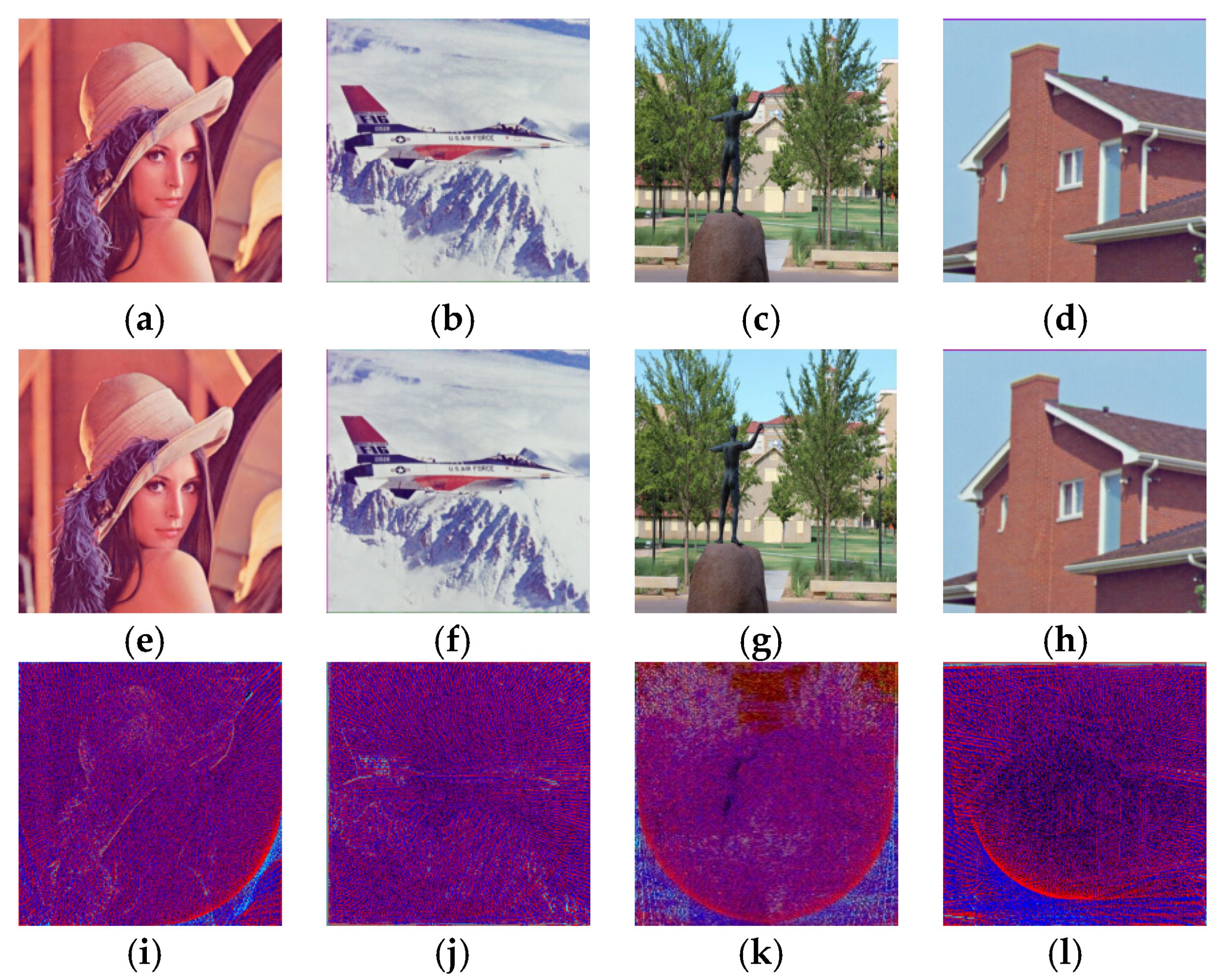
  23. The USC-SIPI Image Database. 2009. Available online: http://sipi.usc.edu/database/ (accessed on 7 January 2019).
Figure 1. Watermark embedding process.
Symmetry 12 00486 g001
Figure 2. Watermark detection process.
Symmetry 12 00486 g002
Figure 3. Host images (a) Lena, (b) F16, (c) TTU, and (d) House; watermarked images (e) Lena, (f) F16, (g) TTU, and (h) House; difference between host images and watermarked images: (il).
Symmetry 12 00486 g003
Figure 4. Watermark image.
Symmetry 12 00486 g004
Figure 5. Analysis of the proposed method under no attack, JPEG compression (QF: 90%), cropping (25%) and rotation (45°) attacks.
Symmetry 12 00486 g005
Figure 6. Analysis of the proposed method under salt and pepper noise (0.01), Gaussian noise (0.1), speckle noise (0.01) and Poisson noise attacks.
Symmetry 12 00486 g006
Figure 7. Analysis of the proposed method under contrast adjustment, sharpening (0.1), wiener filtering, and median filtering attacks.
Symmetry 12 00486 g007
Table 1. Comparative analysis between the suggested algorithm with various recent methods in terms of imperceptibility.
ImageParameterSu et al. [19]Su et al. [20] Khanam et al. [21] Proposed Method
LenaPSNR40.507939.442850.046754.1854
SSIM0.95340.94160.95420.9696
F16PSNR41.609137.172951.643154.1875
SSIM0.95400.93110.94260.9664
TTUPSNR39.480539.678150.754254.1892
SSIM0.95370.94580.93310.9285
HousePSNR39.713441.173948.314354.1823
SSIM0.96630.95240.93720.9579
AveragePSNR40.327739.366950.189654.1861
SSIM0.95680.94270.94180.9595
Table 2. Comparative analysis between the proposed algorithm and several state-of-the-art methods for robustness.
Attack TypeSu et al. [19]Su et al. [20]Khanam et al. [21] (With Key)Khanam et al. [21] (Without Key)Proposed Method
Gaussiannoise (0.1)0.96250.88231.00.93511.0
Specklenoise (0.01)0.96630.96471.00.93491.0
Cropping (25%)0.64820.86191.00.83520.8252
Sharpening (tol = 0.1)0.99350.98821.00.85941.0
Rotation (45°)0.93610.92251.00.51931.0
Wiener filtering0.95780.97651.00.67711.0
Salt and pepper noise (0.01)0.94780.97331.00.99441.0
Median filtering0.94190.89971.00.94591.0
JPEG Compression (90%)0.99980.97911.00.78761.0

