1. Introduction
ELI-NP abbreviation represents Extreme Light Infrastructure-Nuclear Physics facility and is a project incorporating 13 European countries. The researches presented in the paper concern a study of the inertial platform of the project developed in Magurele-Bucharest. This project has two components: a very high intensity laser system (10–30 PW) and a very brilliant, intense γ beam of up to 19 MeV, 0.1 % band width, and 1013 γ/s, both positioned on a concrete insulating platform. The ELI-NP facility has the following purposes: to include new experiments and to upgrade the laser power and gamma beam intensity and energy and to include the most ambitious and far-reaching projects as well as the ones that are yet to be discovered. It may include an upgrade of the γ beam facility, using a superconducting energy recovery linac reaching to higher intensities of 1015 γ/s and improved bandwidth. The realization of the project was possible due to the support provided by the EU and the management and scientific supervision was carried out by an international committee of renowned specialists. The gamma beam system being under construction at ELI-NP will provide a very bright photon beam with unprecedented bandwidth and tunability. To fully take advantage of this performance, a number of interesting physics cases were identified in the WhiteBook [
1] of the ELI-NP project and then detailed in the Technical Design Reports [
2]. Two of the major experimental directions are the study of Nuclear Resonance Fluorescence (NRF) and the study of states above the neutron emission threshold [
3,
4]. Both these experimental set-ups state in their technical design reports the desire to use isotopically enriched targets. The gamma source under construction at ELI-NP is especially well suited for these studies because of the small beam size at the target position which allows matching the full beam flux with a very small target. Nevertheless, this advantage can quickly turn into an experimental quagmire if the overlap between the beam spot at the target position and the target is not very good or at least measurable. To achieve this is necessary to realize a good insulation and to reduce significantly the vibration of the ground transmitted to the platform of the laser and gamma beam system. The researcher must realize a very precise target alignment with the gamma beam and this is not possible if the transmissibility of the vibration is not satisfactory controlled. The design of the inertial platform imposes the implementation of a high precision of positioning the devices, the pieces, the alignment system for the experiments due, in the more general view, to the huge impact on the experiments. This engineering achievement is unique in its size and the results obtained in the design and study of this structure should be known for future projects.
The complexity of the study comes from the fact that the ELI-NP will deliver a beam of high energy photons of unprecedented intensity within a very small opening angle, and for this, the precision become an important thing. Insulation of the base platform is a means of reducing the transmission of vibrations in buildings, and the first attempt to address the problem in this way was in the 60 s (last century) [
5,
6]. Since then, many types of springs have been fitted to many constructions in order to reduce the effects of anthropogenic source vibrations. In most cases, the building rests on steel springs or rubber elements. The aim is to reduce the transmission of vibrations by at least 10 dB for frequencies above 10 Hz, but this goal is rarely achieved [
7]. An important element in insulation is the type of spring used but also important are the cost of operation and the difficulty of implementing the system. A more accurate modeling allows the choice of parameters for the elastic and dissipative elements that correspond as well as are possible to the final purpose of vibration isolation.
The design of inertial platform used to ELI-NP laser project represents a unique achievement realizing the insulation of the laser and gamma beam installations from the excitations that may come from the environment. The solutions found for this project can be useful for similar isolation conditions imposed by other project. Such projects and their design are very rare, and the results obtained within them are even more important, through the information they bring, to the scientific community.
If the platform is considered as a rigid with six degrees of freedom (Steward platform), the isolation methods have been intensively studied. There are several parameters that influence the ability of such a system to be isolated. A study method using a genetic sorting algorithm is developed in [
8]. In these cases, genetic algorithms have been shown to have higher optimization efficiency, better computational accuracy, and reduced optimization time.
A dynamic model for a 6-axis hybrid vibration isolation system based on a cubic configuration of Stewart platform is proposed. The displacement excitations and the loads are simultaneously considered using a Newton-Euler formulation. A force feedback control principle is proposed and studied. Numerical simulation strengthens confidence in the proposed method [
9].
An analysis of a six-degree-of-freedom (DOF) active vibration isolation system is presented in [
10]. The system is applied to isolate a Stewart platform, for a better and precise control and for a wide range of earth-based systems. The paper presents the design and analysis of the platform as a performing and robust vibration isolation system. A prototype has been realized and tested.
Anthropogenic sources of vibration are currently complex due to large flexible structures, activities of all kinds, daily and transport. The inertial platform of a laser system is, in the first approximation, a system with 6 degrees of freedom and can be studied with classical means of analysis. A presentation of these methodologies is made in [
11] in which the latest generation technology and the ways of active vibration isolation for the precise realization of the experiments on the platform are reviewed.
An inerter-based vibration isolation system (IVIS) using an analytical model is established and validated by comparing the experimental and numerical results and is presented in [
12].
A platform to prevent the vibration caused by the low-frequency seismic excitation is presented in [
13]. This design isolates the horizontal and vertical vibrations simultaneously. For this, a combination of a rolling isolation system and four three-parameter isolator with active damping is used. The dynamic model offers the numerical results that show an effective suppression of the vibrations.
In [
14], a new type of vibration isolation to reduce the dynamic response in case of an excitation with wide frequency range is proposed. For installations used in nuclear physics, there are researches presented in [
15,
16,
17,
18].
2. Methodology and Model of the Inertial Platform
The inertial platform is suspended on a number of almost 1000 spring and shock absorber batteries. All installations in the ELI-NP project are located on a platform (
Figure 1) that should be isolated from the influence of any vibrations of the environment. The mass of the entire concrete platform, without partition walls, roofs, and equipment is about 25,000 tons. If you add the partition walls, then it reaches about 35,000 tons, and if you add all the equipment expected and roofs, you get a mass of 54,000 tons. The concrete used for the building is steel reinforced.
The platform is placed on a series of springs and dampers (
Figure 2 and
Figure 3) that have the role of isolating the equipment on the platform from any excitations that could come from the environment. Due to the dimensions of the platform and the particularly large mass, the concrete can deform under the action of its own weight or the weight of the walls and equipment placed over the platform. The numerous springs located at a short distance from each other have the role of uniformizing the loads that appear in the elastic supports of the platform. In this way, the loads that press on the platform as well as its own weight will not give large deformations of the platform plate. The fact that it is possible to act on the springs so that some are active and others do not allow an adjustment and control of the uniformity of the platform support on the base table.
Essentially, the platform consists of two concrete blocks, rigidly connected to each other, placed on spring batteries that evenly distribute the weight on the floor. On the concrete platform are placed massive concrete blocks, with thicknesses of 1600 mm or more, over which are placed concrete slabs as a roof. On this whole structure are placed the equipment and different control and measurement systems. Experiments with laser beam and gamma beam ray are conducted on the concrete platform. The platform must ensure a very good isolation from the anthropic activities around the building, isolation imposed by the experiments that are performed on the platform. At the same time, the platform’s response to an earthquake must be within certain parameters that ensure the integrity of the structure in a high-intensity earthquake.
For the analysis of this structure and of the static and dynamic response to the action of some external (of natural or anthropic source) excitations, a model was made using the finite element method. This method was the main tool used in this paper. Based on the numerical results obtained, a study was made of the deformability of the massive concrete block in static case. It was studied to what extent the deformations of the concrete block can influence the flatness of the entire platform and what would be the influence of additional loads placed on this block, in different positions. Then, the modal numerical analysis of the system was made, obtaining the eigenfrequencies of the elastic structure suspended on the spring batteries. The first three eigenfrequencies represent the frequencies of the rigid movement of the platform mass. In the other modes of vibration, the effect of the deformability of the concrete slabs can be observed.
For the analysis of this structure and of the static and dynamic response to the action of some external, natural, or anthropic excitation, a calculation model was made using the finite element method. This method was the main tool used in this paper. Based on the numerical results obtained, a study was made of the deformability of the massive concrete block in static case. It was studied to what extent the deformations of the concrete block can influence the flatness of the entire platform and what would be the influence of additional loads placed on this block. Then, the modal numerical analysis of the system was made, obtaining the eigenfrequencies of the elastic structure suspended on the spring batteries. The first three eigenfrequencies represent the frequencies of the rigid movement of the platform mass. In the other modes of vibration, the effect of the deformability of the concrete slabs can be observed.
The types of analyzes performed are in the linear domain (linear static analysis). Under these conditions, the equations used follow Hooke’s law. Software used to prepare the model: Altair HyperMesh. Solver for running analysis: OPTISTRUCT. The type of elements used has 4 corner nodes with 24 degrees of freedom (3 × 4 translations + 3 × 4 rotations).
3. Static Analysis
The insulation platform consists of a solid concrete block, made up of two parts, i.e., one of them (which we call the main part) having a thickness of 1600 mm and the other (which we call secondary) having 600 mm. At the dimensions of the construction and at the masses to be placed on top, the deformability of the platform becomes important for obtaining precise (accurate) experiments. For this reason, it is necessary to study the deformability of the concrete platform both under the action of its own weight and as a result of additional loads. The spring suspensions of the platform must be distributed as evenly as possible, and thus, a support system has been designed on about 1000 spring batteries. The inactive elements in the spring batteries can be activated in case of need and can rebalance portions of the platform, leveling its deformations and the tensions that appear in it. Each battery consists of 3–7 springs, and between the springs are located vibration dampers. The springs can be operated (i.e., support the platform) or are not in service, do not support the platform at this time, but can be released and become active, if necessary. Thus, a study was made of the stresses and deformability of the platform placed on the spring batteries, without additional masses placed on top. The finite element method was used to determine the stress and stress that occurs in the platform block.
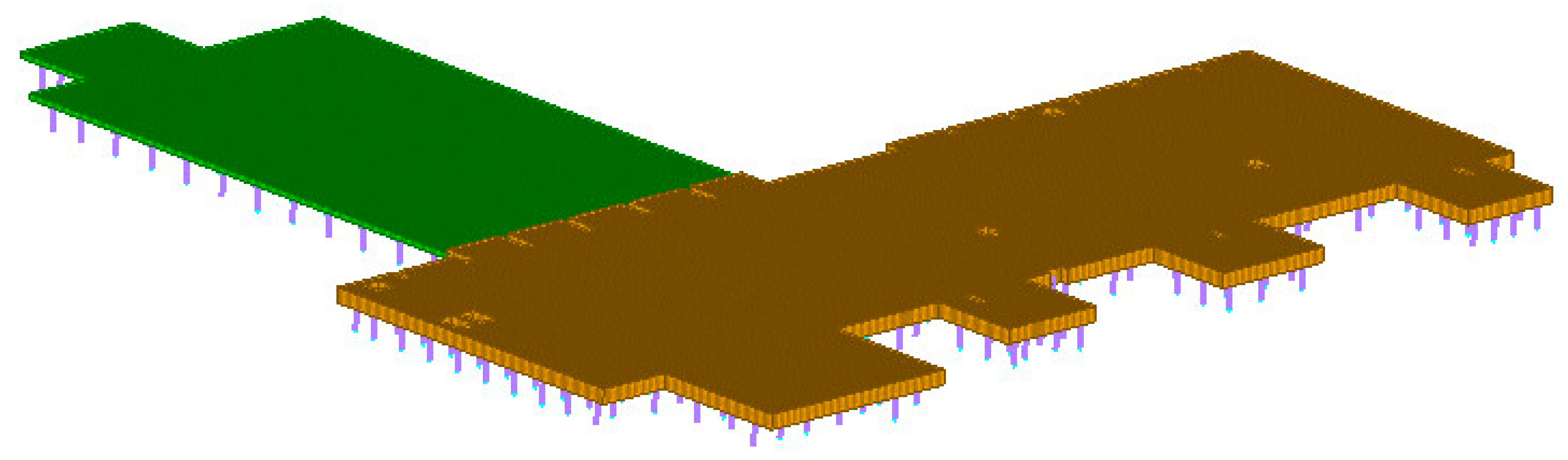
Figure 4 shows the set of two blocks consisting of the main body (shown in yellow, 1600 mm thick) and the secondary body (shown in green, 600 mm thick). The positions where 1000 tons of loads will be applied successively are shown in purple. We put in a limited area, equivalent with the basic surface of a wall (approx. 20 m
2), the considered supplementary mass.
In
Figure 5,
Figure 6,
Figure 7,
Figure 8,
Figure 9,
Figure 10, and
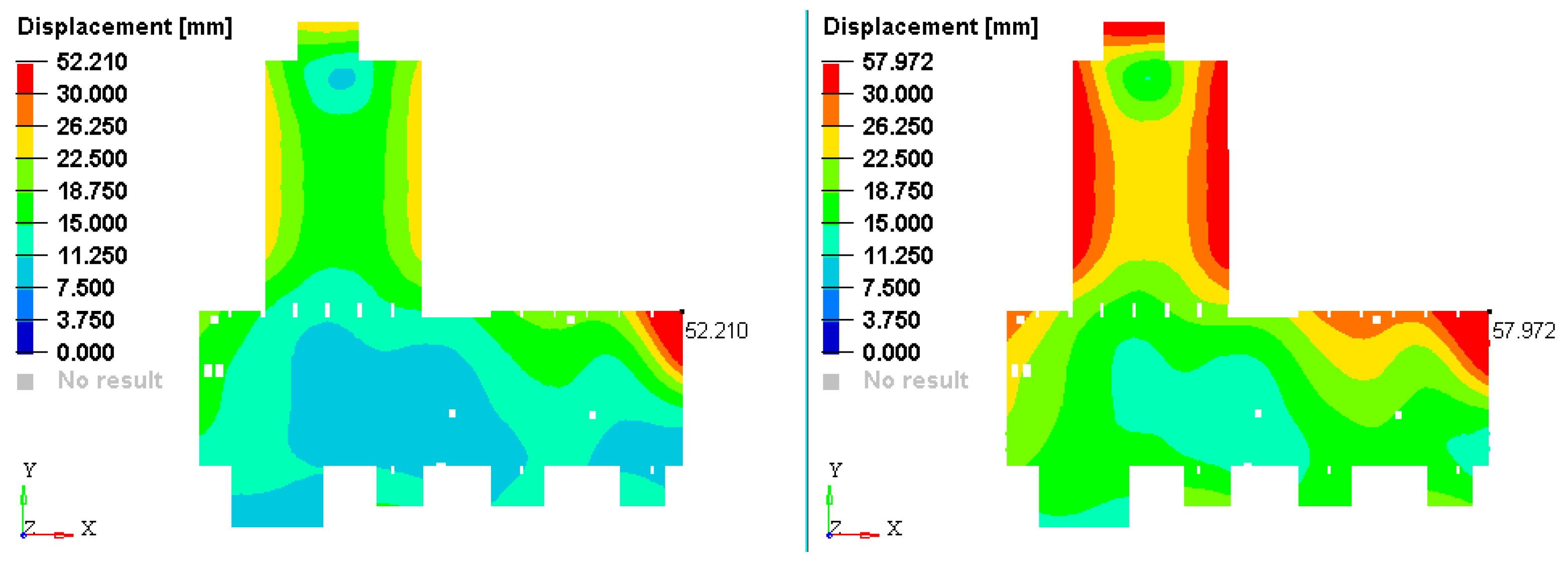
Figure 11, two cases are presented in parallel: the case of the unloaded platform (total mass 25,000 tons) and the case of the platform with vertically mounted walls (total mass 35,000 tons). The deformation of the concrete platform loaded with its own weight; placed on the spring batteries, is presented in
Figure 5, i.e., on the left is the 25,000 ton variant, while on the right is the 35,000 ton variant.
Figure 6 shows the deformability of the platform if the load of 1000 tons is applied in point 1. A logarithmic scale is used for a better visualization of the deformation situation. In
Appendix A, the deformations using a linear scale are represented (
Figure A1,
Figure A2,
Figure A3 and
Figure A4).
The finite element model used has a number of 50,898 nodes and a number of elements of 50,053. CBUSH type elements (12 degrees of freedom) were used for modeling the spring batteries, and QUAD4 plate elements (24 degrees of freedom per element) were used for the discretization of the element plates [
19,
20,
21,
22]. The mechanical properties of the concrete, used in this paper, are obtained from literature [
23]. We mention that the concrete is reinforced with steel. In this case, it is expected that the Young’s Modulus can increase. Some studies [
24,
25] show that, in reality, the increase in the Young’s modulus is not significant. For a fiber volume ratio of 0.025, the Young’s modulus is 30.000 N/mm
2, the value considered in our study. In [
26] has been presented the values of reinforced concrete offered by Eurocode (Structural design calculations according to Eurocodes). The Poisson’s ration used is 0.2, as recommended by [
26]. The connection with the ground, after the three directions, is made by means of suspension springs. The springs are fixed to the ground and are connected to the inertial mass (boundary conditions). The rigidity of a single spring is k
z = 1.85e + 6N/m after the vertical direction and kx = ky = 0.55e + 6 N/m for the other two directions. The dampers have the coefficient c
x = c
y = cz = 2000 kNs/m.
In order to see how the placement of additional weights or the removal of weights from the platform can influence the deformability of the platform, it was considered an operation that was performed in the modification of a concrete wall placed in position 4 in
Figure 12. The wall that was removed weighed 250 tons. The deformation field in the two cases was presented in
Figure 12. If the figure is analyzed, it is found that there are no significant differences between the two situations, i.e., the removal of a wall of 250 tons will not significantly influence the placement of the platform.
4. Modal Analysis
The elastic elements that influence the vibration behavior of the platform are the spring batteries on which the platform is placed and the deformability of the platform under the action of its own weight, the weight of the walls, and the weight of the equipment.
Analysis of the vibrations of the concrete slab placed on the spring batteries is made using the model with finite elements presented in
Section 3 [
27,
28,
29,
30,
31]. We are interested in the vibrations of the concrete platform caused by the elastic suspension based on placement the equations of motion of the platform are given by:
where
is the inertial matrix,
is the
damping matrix,
is the stiffness matrix (these three matrix are real, symmetric and positive definite),
is the vector of generalized displacements,
is the column vector of velocities, and
is the vector of the generalized accelerations.
Let us consider the form free vibrations of this system, a particular expression of (1):
then, the time dependence of
is harmonic
where
C is constant,
is the circular frequency, and
is the initial phase shift.
Substitution of (3) into (2) yields
Equation (4) has nontrivial solutions if and only if:
If
n is the dimension of the system, Equation (5) represents a polynomial:
with the real and positive solutions:
. Equation (6) possesses, in general,
n distinct roots, referred to as eigenvalues. For every
, the linear homogeneous system (4) is written in the form:
we obtain the solution
,
. These vectors are the eigenmodes of vibration.
The case of multiple roots is not considered herein. The square roots of the eigenvalues are the system of natural frequencies,
, usually presented in order of increasing magnitude (see
Table 1).
In the paper, a calculation was made of the eigenfrequencies (resonance frequencies) and of the eigenmodes of vibration of the concrete slab. In
Figure 13,
Figure 14,
Figure 15,
Figure 16,
Figure 17,
Figure 18,
Figure 19,
Figure 20,
Figure 21, and
Figure 22, the first 10 modes of vibration are represented. Modes 10–20 are represented in
Appendix C (
Figure A5,
Figure A6,
Figure A7,
Figure A8,
Figure A9,
Figure A10,
Figure A11,
Figure A12,
Figure A13,
Figure A14 and
Figure A15).
5. Discussion
The paper studies the response of the inertial platform supported on sets of spring batteries on ground base to identify if excessive vibrations exist and how are the different ground vibration transmitted to the platform. On the platform, a lot of devices and instruments are distributed implying in the scientific researches and the necessary annexes. Usually, vibrations coming from the vehicles and other anthropic activities and transmitted through the ground are nonstationary vibrations. To reduce the influence of these vibrations on the inertial platform, this is suspended on a set of spring batteries and dampers that can be activated or not. This suspension constitutes an excellent tool to reduce the transfer of the unwanted vibrations to the studied platform.
The deformability of the concrete platform under the action of its own weight and under the action of the weight of the walls is also studied. It is found that the relative deformations and stresses that occur in the platform material are relatively small, so there are no problems related to the strength and cracking of the platform, even if it is charged at high loads.
The platform consists of two plates, one main, on which are found most of the instruments and devices and where the massive partition walls are raised, which is about 1600 mm, and the second platform, which I called secondary, smaller and thinner, is only 600 mm, and weighs about half the weight of the unloaded main board. If the main board is loaded with all the equipment and partitions, the platform weighs about 1/6 of the total weight of the platform. This platform is found to have significant amplitudes in its eigenmodes, so in the case of external excitations with frequencies close to the natural frequencies of the entire platform, we can expect an amplification of these excitations at the secondary platform. The problem can be solved by activating additional springs from the spring batteries that support the secondary platform.
Additionally, another problem that can be mentioned is the fact that the eigenfrequencies of the platform are found in the range where the earthquakes that take place in the area have the excitation frequencies.
6. Conclusions and Future Works
The results based on the obtained model allow the formulation of some conclusions regarding the achievement of the objectives proposed within the project. The static analysis of the platform indicates that under the action of its own weight, supported on the elastic springs, the platform deforms the most by 26 mm, which corresponds to a strain of about 0.1%. In addition, under the action of additional weights that could appear on the platform (mainly these weights are represented by different dividing concrete walls), the deformations that can occur are not important. The calculation made with masses of 1000 tons (much exaggerated compared to the real situation—the hardest wall we identified has less than 250 tons) placed in different parts of the platform indicated to us, in the most unfavorable case, a deformation of about 250 mm corresponding to a strain of 1%. This situation shows us that any constructions on the platform or changes in the architecture will not influence its flatness and, therefore, the operation of the measuring instruments that impose certain strict conditions.
The dynamic analysis of the platform indicates a large number of natural frequencies below 5 Hz, which is a negative aspect from the point of view of the platform’s behavior in earthquakes. Anthropic activities will not influence the behavior of the system, taking into account the frequencies generated by these activities. Instead, the effects of a catastrophic event (earthquake) could amplify the possibilities of vibration in certain directions of the platform, which could lead to destruction and damage to the installation. For this reason, a careful calculation is required to the structure’s response in case of an earthquake and its permanent monitoring for the analysis of the transmissibility of external excitations. The ELI-NP project has a decoupling system for earthquakes, the need for an additional isolation system of the entire mass should be studied. Such a study, the necessity of which has been demanded by the researches made, is to be carried out.
Author Contributions
Conceptualization, S.V., P.B., C.I., P.N.B. and D.L.; methodology, S.V. and C.I.; software, C.I.; validation, C.I., S.V., P.B. and D.L.; formal analysis, P.N.B., S.V., P.B. and D.L.; investigation, C.I. and S.V.; resources, S.V.; data curation, C.I. and S.V.; writing—original draft preparation, C.I., S.V., P.B., D.L. and P.N.B.; writing—review and editing, C.I., S.V., P.B., P.N.B. and D.L.; visualization, S.V. and P.B.; supervision, S.V.; project administration, S.V.; funding acquisition, P.B. All authors have read and agreed to the published version of the manuscript.
Funding
This research was funded by IFA-MG, grant number 16/2016. The APC was funded by the Transylvania University of Brasov.
Acknowledgments
We want to thank the reviewers who have read the manuscript carefully and have proposed pertinent corrections that have led to the improvement of our manuscript.
Conflicts of Interest
The authors declare no conflict of interest. The funders had no role in the design of the study; in the collection, analyses, or interpretation of data; in the writing of the manuscript; or in the decision to publish the results.
Appendix A
Figure A1.
Deformation of the concrete platform placed on the spring batteries: (a) under its own weight and (b) loaded with 1000 tons in point 1.
Figure A1.
Deformation of the concrete platform placed on the spring batteries: (a) under its own weight and (b) loaded with 1000 tons in point 1.
Figure A2.
Deformation of the concrete platform (a) loaded with 1000 tons in points 2 and (b) loaded with 1000 tons in point 3.
Figure A2.
Deformation of the concrete platform (a) loaded with 1000 tons in points 2 and (b) loaded with 1000 tons in point 3.
Figure A3.
Deformation of the concrete platform (a) loaded with 1000 tons in points 4 and (b) loaded with 1000 tons in point 5.
Figure A3.
Deformation of the concrete platform (a) loaded with 1000 tons in points 4 and (b) loaded with 1000 tons in point 5.
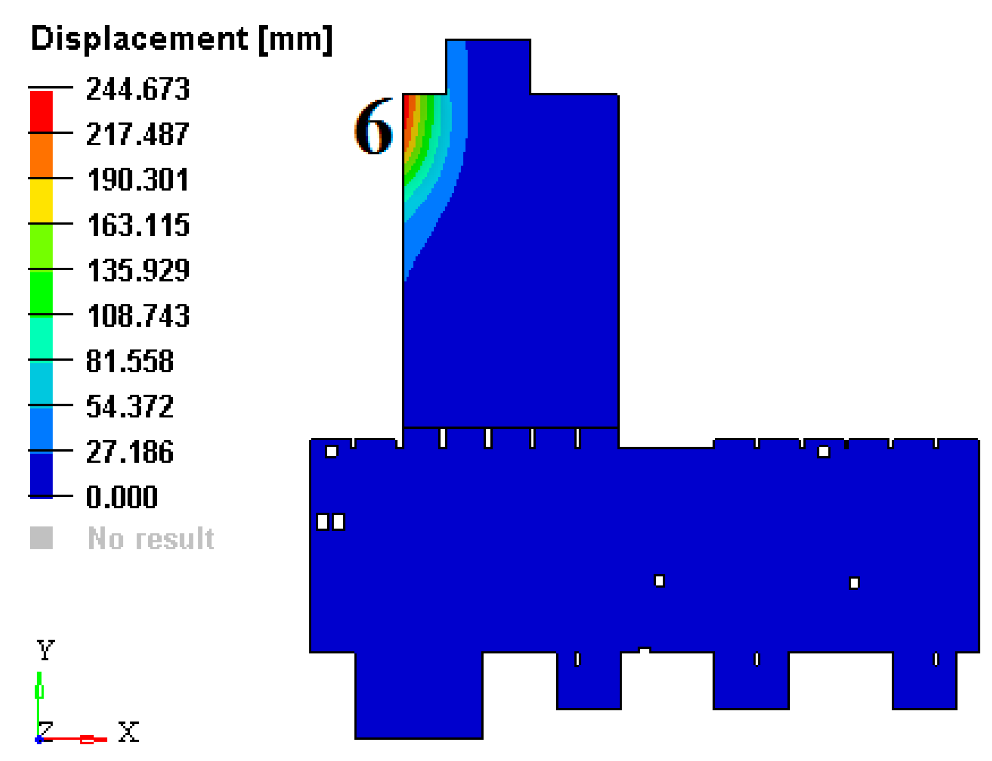
Figure A4.
Deformation of the concrete platform loaded with 1000 tons in points 6.
Figure A4.
Deformation of the concrete platform loaded with 1000 tons in points 6.
Comment: The load of 1000 tons represents only a hypothetical load, to see how the platform deforms in extreme situations. In practical cases, it is hard to believe that a task will be added, even 10 times less, in point 6 studied. Usually, a large load can occur when a wall is realized or removed. A real situation was encountered when a 250 tons wall was removed. The deformation in this case was much smaller than the one calculated for the hypothetical case. A simulation with a heavier wall was made in
Figure 12. It has been found that in this case, the difference between deformations was much smaller. At the same time, the dimensions of the structure are of the order of tens of meters and 250 mm compared to 25 m representing a strain of 1%.
Appendix B. Stress Field in the Platform (Expressed in MPa)
Figure A5.
Stresses in the concrete platform expressed in MPa. (a) under its own weight; (b) loaded with 1000 tons in point 1; (c) loaded with 1000 tons in points 2 and (d) loaded with 1000 tons in point 3; (e) loaded with 1000 tons in points 4 and (f) loaded with 1000 tons in point 5; (g) loaded with 1000 tons in points 6.
Appendix C
Figure A10.
Eigenmode 15. (a) perspective and (b) top view.
Figure A10.
Eigenmode 15. (a) perspective and (b) top view.
Figure A11.
Eigenmode 16.
Figure A11.
Eigenmode 16.
Figure A12.
Eigenmode 17.
Figure A12.
Eigenmode 17.
Figure A13.
Eigenmode 18. (a) perspective and (b) top view.
Figure A13.
Eigenmode 18. (a) perspective and (b) top view.
Figure A14.
Eigenmode 19. (a) perspective and (b) top view.
Figure A14.
Eigenmode 19. (a) perspective and (b) top view.
Figure A15.
Eigenmode 20.
Figure A15.
Eigenmode 20.
References
- The White Book of ELI Nuclear Physics Bucharest-Magurele, Romania. Available online: http://www.eli-np.ro/whitebook.php (accessed on 31 October 2020).
- Serafini, L. EuroGammaS proposal for the ELI-NP Gamma beam System. Technical Design Report, July. 2014. Technical Design Report. Available online: https://arxiv.org/ftp/arxiv/papers/1407/1407.3669.pdf (accessed on 31 October 2020).
- Habs, D.; Tajima, T.; Zamfir, V. Extreme Light Infrastructure–Nuclear Physics (ELI–NP): New Horizons for Photon Physics in Europe. Nucl. Phys. News 2011, 21, 23–29. [Google Scholar] [CrossRef]
- J. Welch Ground Vibration and Siting of the Cryogenics Facility for Cornell ERL Prototype. Technical Design Report. Available online: https://www.classe.cornell.edu/public/ERL/2002/ERL02-3/ERL02-3.pdf (accessed on 25 November 2020).
- Arnold, C. Seismic Design & Devices for Detaching Building from the Ground. Archit. AIA J. 1987, 76, 64–67. [Google Scholar]
- Tarics, A.G. Base-Isolation—A New Strategy for Earthquake Protection of Buildings. J. Archit. Plan. Res. 1987, 4, 64–76. [Google Scholar]
- Teramoto, T. Recent Current of Nase Isolation and Seismic Control-System for Building Structure. Tetsu Hagane J. Iron Steel Inst. Jpn. 1987, 73, S348. [Google Scholar]
- Jiang, M.; Rui, X.; Zhu, W.; Yang, F.; Zhang, Y. Optimal design of 6-DOF vibration isolation platform based on transfer matrix method for multibody systems. Acta Mech. Sin. 2020, 1–11. [Google Scholar] [CrossRef]
- Han, P.; Wang, T.; Wang, D.H. Modeling and control of a Stewart platform based six-axis hybrid vibration isolation system. In Proceedings of the 2008 7th World Congress on Intelligent Control. and Automation, Chongqing, China, 25–27 June 2008; Volume 1–23, pp. 1613–1618. [Google Scholar] [CrossRef]
- Geng, Z.; Haynes, L.S. Six-degree-of-freedom active vibration isolation using a stewart platform mechanism. J. Robot. Syst. 1993, 10, 725–744. [Google Scholar] [CrossRef]
- Liu, L.; Wang, B. Development of stewart platforms for active vibration isolation and precision pointing. In Proceedings of the International Conference on Smart Materials and Nanotechnology in Engineering, Harbin, China, 1–4 July 2007. [Google Scholar]
- Ma, R.; Bi, K.; Hao, H. Heave motion mitigation of semi-submersible platform using inerter-based vibration isolation system (IVIS). Eng. Struct. 2020, 219, 110833. [Google Scholar] [CrossRef]
- Xie, X.; Diao, J.; Xu, Y.; Zhang, Z. Performance of a low-frequency hybrid vibration isolation platform for vibration-sensitive devices. J. Low Freq. Noise, Vib. Act. Control. 2018, 37, 1164–1175. [Google Scholar] [CrossRef] [Green Version]
- Xu, Z.-D.; Xu, F.-H.; Chen, X. Vibration suppression on a platform by using vibration isolation and mitigation devices. Nonlinear Dyn. 2015, 83, 1341–1353. [Google Scholar] [CrossRef]
- Assmann, R.; Jeanneret, B.; Verdier, A.; Vos, L.; Wildner, E.; Zimmermann, F.; Brinkmann, R.; Montag, C.; Reyzl, I.; Walker, N.; et al. Stability considerations for final focus systems of future linear collinder. In Proceedings of the 7th European Conference, EPAC 2000, Vienna, Austria, 26–30 June 2000; p. 447. [Google Scholar]
- Bolzon, B. Etude des Vibrations et de la Stabilisation à L’échelle Sous-Nanométrique des Doublets Finaux d’un Collisionneur Linéaire. Ph.D. Thesis, Université Chambery Annecy de Savoie, Chambéry, France, 2007. [Google Scholar]
- A Multi-Tev Linear Collider Based on Clic Technology, Conceptual Design Report. KEK Report 2012-1, Geneva. 2012. Available online: http://cds.cern.ch/record/1601966/files/ILCTDR-VOLUME_1.pdf. (accessed on 31 October 2020).
- Artoos, K. Compatibility and Integration of a CLIC Quadrupole Nanometre-Stabilization and Positioning system in a Large Accelerator Environment. In Proceedings of the 1st International Particle Accelerator Conference (IPAC’10), Kyoto, Japan, 23–28 May 2010; Volume 16, pp. 1274–1276. [Google Scholar]
- Vlase, S.; Marin, M.; Öchsner, A.; Scutaru, M.L. Motion equation for a flexible one-dimensional element used in the dynamical analysis of a multibody system. Contin. Mech. Thermodyn. 2019, 31, 715–724. [Google Scholar] [CrossRef]
- Marin, M. Some basic theorems in elastostatics of micropolar materials with voids. J. Comput. Appl. Math. 1996, 70, 115–126. [Google Scholar] [CrossRef] [Green Version]
- Itu, C.; Öchsner, A.; Vlase, S.; Marin, M. Improved rigidity of composite circular plates through radial ribs. Proc. Inst. Mech. Eng. Part. L J. Mater. Des. Appl. 2019, 233, 1585–1593. [Google Scholar] [CrossRef]
- Scutaru, M.L.; Vlase, S.; Marin, M. New analytical method based on dynamic response of planar mechanical elastic systems. Bound. Value Probl. 2020, 104. [Google Scholar] [CrossRef]
- Nazreen, M.S.; Mohamed, R.N.; Ab Kadir, M.A.; Azillah, N.; Shukri, N.A.; Mansor, S.; Zamri, F. Characterization of lightweight concrete made of palm oil clinker aggregates. MATEC Web Conf. 2018, 250, 03002. [Google Scholar] [CrossRef]
- Gul, M.; Bashir, A.; Naqash, J.A. Study of Modulus of Elasticity of Steel Fiber Reinforced Concrete. Int. J. Eng. Adv. Technol. 2014, 3. ISSN: 2249-8958. Available online: https://www.ijeat.org/wp-content/uploads/papers/v3i4/D2995043414.pdf (accessed on 31 October 2020).
- Yusof, M.A.; Nor, N.M.; Fauzi, M.; Zain, M.; Ismail, A.; Sohaimi, A.; Zaidi, A.M. Mechanical Properties of Hybrid Steel Fibre Reinforced Concrete with Different Aspect Ratio. Aust. J. Basic Appl. Sci. 2011, 5, 159–166. [Google Scholar]
- Eurocode Applied. Available online: https://eurocodeapplied.com/design/en1992/concrete-design-properties (accessed on 25 November 2020).
- Vlase, S. Elimination of lagrangian multipliers. Mech. Res. Commun. 1987, 14, 17–22. [Google Scholar] [CrossRef]
- Rades, M. Mechanical Vibration, II, Structural Dynamics Modeling; Printech Publishing House: Bangalore, Karnataka, India, 2010. [Google Scholar]
- Vlase, S.; Negrean, I.; Marin, M.; Scutaru, M.L. Energy of Accelerations Used to Obtain the Motion Equations of a Three- Dimensional Finite Element. Symmetry 2020, 12, 321. [Google Scholar] [CrossRef] [Green Version]
- Hu, R.; Iwamoto, S.; Feng, L.; Ju, S.; Hu, S.; Ohnishi, M.; Nagai, N.; Hirakawa, K.; Shiomi, J. Machine-Learning-Optimized Aperiodic Superlattice Minimizes Coherent Phonon Heat Conduction. Phys. Rev. X 2020, 10, 021050. [Google Scholar] [CrossRef]
- Imani, M.; Ghoreishi, S.F. Bayesian Optimization Objective-Based Experimental Design. In Proceedings of the 2020 American Control Conference (ACC), Denver, CO, USA, 1–3 July 2020. [Google Scholar]
Figure 1.
(a) Platform under its own weight. (b) Platform with partition walls.
Figure 1.
(a) Platform under its own weight. (b) Platform with partition walls.
Figure 2.
Platform supported on batteries of springs.
Figure 2.
Platform supported on batteries of springs.
Figure 3.
Platform with partition walls and roofs (detail).
Figure 3.
Platform with partition walls and roofs (detail).
Figure 4.
The platform made by two solid blocks.
Figure 4.
The platform made by two solid blocks.
Figure 5.
Case (a) plate under its own weight.
Figure 5.
Case (a) plate under its own weight.
Figure 6.
Case (b) plate loaded with 1.000 tons, placed in pct.1.
Figure 6.
Case (b) plate loaded with 1.000 tons, placed in pct.1.
Figure 7.
Case (c) plate loaded with 1.000 tons, placed in pct.2.
Figure 7.
Case (c) plate loaded with 1.000 tons, placed in pct.2.
Figure 8.
Case (d) plate loaded with 1.000 tons, placed in pct.3.
Figure 8.
Case (d) plate loaded with 1.000 tons, placed in pct.3.
Figure 9.
Case (e) plate loaded with 1.000 tons, placed in pct.4.
Figure 9.
Case (e) plate loaded with 1.000 tons, placed in pct.4.
Figure 10.
Case (f) plate loaded with 1.000 tons, placed in pct.5.
Figure 10.
Case (f) plate loaded with 1.000 tons, placed in pct.5.
Figure 11.
Case (f) plate loaded with 1.000 tons, placed in pct.6.
Figure 11.
Case (f) plate loaded with 1.000 tons, placed in pct.6.
Figure 12.
Comparison between the deformations of the standard plate and the deformations after removing a 250 tons wall: (a) deformation field for the initial platform and (b) deformation field if a wall is removed. There are no significant differences between in the two cases.
Figure 12.
Comparison between the deformations of the standard plate and the deformations after removing a 250 tons wall: (a) deformation field for the initial platform and (b) deformation field if a wall is removed. There are no significant differences between in the two cases.
Figure 13.
Eigenmode 1. .
Figure 13.
Eigenmode 1. .
Figure 14.
Eigenmode 2. .
Figure 14.
Eigenmode 2. .
Figure 15.
Eigenmode 3. .
Figure 15.
Eigenmode 3. .
Figure 16.
Eigenmode 4. .
Figure 16.
Eigenmode 4. .
Figure 17.
Eigenmode 5. .
Figure 17.
Eigenmode 5. .
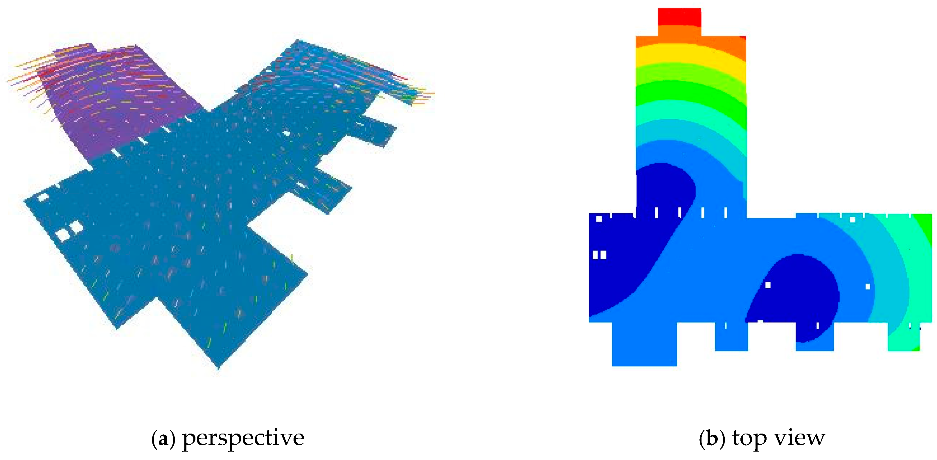
Figure 18.
Eigenmode 6. .
Figure 18.
Eigenmode 6. .
Figure 19.
Eigenmode 7. .
Figure 19.
Eigenmode 7. .
Figure 20.
Eigenmode 8. .
Figure 20.
Eigenmode 8. .
Figure 21.
Eigenmode 9. .
Figure 21.
Eigenmode 9. .
Figure 22.
Eigenmode 10. .
Figure 22.
Eigenmode 10. .
Table 1.
Eigenfrequencies (in Hz).
Table 1.
Eigenfrequencies (in Hz).
| Nr. | 25,000 Tons | 35,000 Tons | 54,000 Tons |
|---|
| 1 | 2.27 | 1.90 | 1.53 |
| 2 | 2.43 | 2.03 | 1.64 |
| 3 | 2.49 | 2.08 | 1.68 |
| 4 | 3.38 | 2.82 | 2.28 |
| 5 | 3.40 | 2.84 | 2.29 |
| 6 | 3.45 | 2.89 | 2.33 |
| 7 | 3.60 | 3.01 | 2.42 |
| 8 | 3.66 | 3.06 | 2.47 |
| 9 | 3.89 | 3.26 | 2.62 |
| 10 | 3.92 | 3.28 | 2.64 |
| 11 | 4.00 | 3.34 | 2.69 |
| 12 | 4.04 | 3.38 | 2.73 |
| 13 | 4.14 | 3.46 | 2.78 |
| 14 | 4.38 | 3.66 | 2.95 |
| 15 | 4.42 | 3.69 | 2.96 |
| 16 | 4.43 | 3.71 | 2.98 |
| 17 | 4.52 | 3.78 | 3.04 |
| 18 | 4.57 | 3.82 | 3.07 |
| 19 | 4.60 | 3.85 | 3.10 |
| 20 | 4.64 | 3.88 | 3.12 |
| 21 | 4.72 | 3.95 | 3.19 |
| 22 | 4.79 | 4.00 | 3.23 |
| 23 | 4.97 | 4.16 | 3.36 |
| 24 | 5.04 | 4.21 | 3.4 |
| 25 | 5.06 | 4.23 | 3.41 |
| 26 | 5.18 | 4.33 | 3.49 |
| 27 | 5.33 | 4.46 | 3.6 |
| 28 | 5.42 | 4.54 | 3.66 |
| 29 | 5.57 | 4.66 | 3.76 |
| 30 | 5.64 | 4.72 | 3.8 |
| 31 | 5.67 | 4.74 | 3.83 |
| 32 | 5.84 | 4.88 | 3.94 |
| 33 | 6.05 | 5.06 | 4.08 |
| 34 | 6.3 | 5.27 | 4.25 |
| 35 | 6.38 | 5.33 | 4.31 |
| 36 | 6.62 | 5.53 | 4.47 |
| 37 | 6.69 | 5.59 | 4.51 |
| 38 | 6.90 | 5.77 | 4.66 |
| 39 | 7.10 | 5.93 | 4.79 |
| 40 | 7.13 | 5.96 | 4.81 |
| Publisher’s Note: MDPI stays neutral with regard to jurisdictional claims in published maps and institutional affiliations. |
© 2020 by the authors. Licensee MDPI, Basel, Switzerland. This article is an open access article distributed under the terms and conditions of the Creative Commons Attribution (CC BY) license (http://creativecommons.org/licenses/by/4.0/).


